Abstract
A planetary thread roller bearing (PTRB) is a state-of-the-art component in electromechanical actuators (EMA) due to its high load-bearing capacity and small volume. The study of the PTRB is a leading task in the domain of EMA application. In this study, we propose a mathematical model of PTRB friction torque on its working principle and causes. Specifically, the impact of basic properties of the PTRB on friction torque, i.e., rotating speed and external load, are modeled and analyzed. To verify the variation principle of friction torque, experiments are carried out on an actual PTRB. For the test PTRB, the rotating speed ranges from 200 to 2000 rpm with a reverse load from 2000 to 30,000 N at a constant temperature of 55 °C. Experimental results verify the effectiveness of the mathematical model under conditions of 200–2000 rpm rotating speed and 2000–30,000 N external load, which establish strong evidence for model accuracy and robustness.
1. Introduction
Electromechanical actuators (EMAs) have higher energy efficiency and better dynamic characteristics that clearly outperform traditional counterparts and hydraulic pipelines for electrical aircrafts [1,2]. In the context of power transmission, EMAs are capable of precisely matching the torque and speed between the motor and the external load, which is dependent on the planetary roller screw (PRS) [3]. Specifically, the planetary roller screw can be regarded a mechanical device that converts rotary motion to linear motion; see Figure 1 [4]. A PRS is mainly composed of a screw, nut, set of rollers, as well as the bearings. The rotating screw causes the rolling of the rollers, and thus, the moving of the nut [5]. Meanwhile, the bearings support the rotating parts and reduce the friction coefficient, effectively ensuring precise rotation [6].
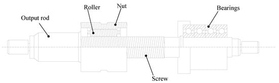
Figure 1.
Planetary roller screw mechanism.
More recently, the structure optimization of the EMA is highlighted. In the context of EMA applications, an improvement in load capacity and working efficiency is most pronounced. Notably, the actuating systems must meet the demands of increasingly large axial and radial torques due to working conditions. Moreover, for the purpose of system minimization and integration, researchers tend to perform more functions with even fewer components. Reductions in system weight and space with better working performance have also been proposed [7]. State-of-the-art initiatives, such as Long Beach Rocketry by NASA, have identified their exploration of the advancement of transmission mechanisms [8].
Promisingly, a planetary thread roller bearing (PTRB) is devised, which could facilitate the operation of the current planetary roller screw as well as in system optimization [9,10]. Instead of focusing on material adoption and machining processing [11,12], the PTRB is developed by integrating threaded coupling pairs into the bearing balls. Compared with classical bearings, the PTRB is distinctive in its load-bearing capacity; see Table 1 [13]. Considering both the radial and axial loads, there is a considerable gap between the PTRB and other categories of bearings. That is, by substituting the rolling balls with the roller-nut pair, an even load-bearing capacity is accessible. In addition, the installation of the PTRB saves a substantial amount of volume and weight, because most widely-used bearings hold the external load in a single direction and have to be mounted in pairs. As such, the application of the PTRB gives rise to system integration and minimization. In contrast, the superiority in rotating speed is marginal. A large external load inevitably results in a large friction torque, which causes severe heat generation at high speeds and can even damage the structure.

Table 1.
Specifications of different bearings.
Considering the significance of EMA and its applications, the PTRB is currently far from being put to practical use [14]. System reliability and verification of working properties is always taken as the redlines. For this reason, more effort is needed to define the PTRB before it becomes widespread. Despiteits delicate design, ongoing research tends to analyze the basic properties of the PTRB under different working conditions of EMA.
The objective of this study is to study friction torque based on the devising of the PTRB. As an essential characteristic, friction torque has certain effects on the working performance of the PTRB [15,16]. Starting with analyzing its mechanical structure, the working model of friction torque is set up based on its generating causes. In this way, the impacts of two basic properties, i.e., rotating speed and external load, are thoroughly analyzed. The proposed friction torque model, together with theoretical values, is investigated under various working conditions. Model performance is then verified through extensive experiments on actual PTRBs.
The contributions of this paper are threefold and summarized as follows:
Considering the PTRB structure and its working principle, the friction torque model is established, paving a way for further analysis of PTRB friction during operation.
The effects on friction torque of basic working variables, i.e., external load and rotating speed, are closely investigated. The variation rules of friction torque in line with these parameters are obtained.
Experiments are performed to detect PTRB friction torque variation under practical working conditions. Experimental results verify the effectiveness of the theoretical analysis of the friction torque.
The rest of this paper is organized as follows: we describe the structure of the PTRB and its contact property in Section 2. Section 3 is dedicated to presenting the friction torque computing model of the PTRB. In Section 4, we explore the impacts of rotating speed and external load on friction torque with an analysis of different working conditions. Experiments are performed to measure the actual friction torque of working PTRB and verify the effectiveness of the friction torque model in Section 5. Finally, concluding remarks of this work are given in Section 6.
2. Prerequisite
2.1. Structure Description
The design of the PTRB is both creative and practical. Figure 2 presents the mechanical structure of the PTRB. There are five major components: two retaining rings, two planetary carriers, an inner ring, an outer ring, and a set of threaded rollers [17]. The teeth of the threaded rollers can mesh with both the inner and outer ring. The multiple annular threads (i.e., the lead equals zero) are within the aforementioned three parts and the clearance between each annular thread is the same. Specifically, the thread profile of the threaded rollers is a double circular arc whereas those of the inner and outer rings are trapezoid. Holes to hold the threaded rollers are evenly distributed on the planetary carrier. The retaining rings prevent the planetary carriers from falling off, as well as eliminate the backlash between every two thread teeth.
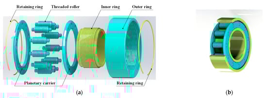
Figure 2.
Structure of PTR: (a) exploded view and (b) three-dimensional structure.
Similar to the PRS, the PTRB aims to convert rotary into linear motion. During operation, the outer ring is fixed, and the inner ring can rotate freely. The threaded rollers roll inside the bearing when the screw rotates, which can be regarded as the planetary rolling motion between the inner ring and the outer ring via meshing. As long as the threaded rollers rotate, there is revolution around the screw as well.
According to the thread shape, the contact between each threaded roller and the bearing rings can be taken as that between a steel ball and plane. The effective ball within the two contact pairs is shown in Figure 3. The diameter of the effective ball is larger than that of a single threaded roller. For the same material, the larger the size, the greater the load it can bear. We shall thus derive that the PTRB can handle an even higher load from the axial and radial directions. In other words, the PTRB can be applied to the same loading conditions by occupying smaller space.
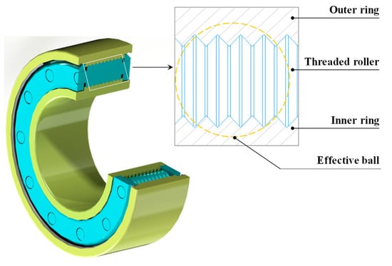
Figure 3.
Contact of threaded rollers with bearing rings.
2.2. Contact Property
Hertzian contact theory is widely applied to deal with issues of elastomer contact [18,19]. On this occasion, we employ Hertzian theory to resolve the contact between threaded rollers and bearing rings.
Due to its multi-thread structure, the load distribution of the three components varies. The threaded roller is in an equilibrium of forces during operation. In this way, force is transmitted via the thread meshing processes. Seeing that there are two contact pairs established for transmission, which are threaded roller to inner ring pair and roller to outer ring pair, we tend to illustrate the load distribution based on the roller to inner ring contact pair as an example. The meshing of the threaded roller with the inner ring is exhibited in Figure 4. The elastic deformation amount caused by the contact is:
where stands for the elastic deformation of thread, is an elliptic integral of the first kind, is the load on that thread (Figure 4), and is a dimensionless parameter related to the main curvature of the meshing pair. Further, and are the elastic modulus and the Poisson ratio of the inner ring, respectively, whereas and are those of the threaded roller.
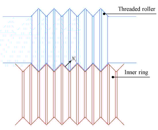
Figure 4.
Contact between threaded roller and inner ring.
We define the equivalent elastic modulus of the inner ring and the threaded roller as:
As shown in Equation (1), the deformation amount is proportional to of the force on the thread tooth. Therefore, the elastic deformation can also be denoted by:
together with
Specifically, the main curvature refers to the sum of meshing components at the contact point. As mentioned above, the thread profile of both the inner and outer rings are plane, whereas the contour of the threaded roller is curved. Hence, both contact pairs can be regarded as arc-plane pairs [20].
Based on Hertzian contact theory, we can get two mutually perpendicular planes through the contact point of the contact pair, which are also perpendicular to the common tangent plane. The geometric relation of the two parts is shown in Figure 5. In spite of the basic radius of the contact components, i.e., the threaded roller and inner ring, there also exists an equivalent curvature radius in the two mutually perpendicular planes. For the threaded roller, we can get its curvature radii, namely and , in both planes, by:
where , and represent the elemental radius, the thread diameter, and the contact angle of threaded roller, respectively.
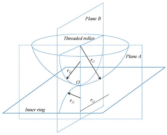
Figure 5.
Geometric relation of contact.
Likewise, when the thread of the inner ring is simplified into a plane, the curvature radii ( and ) of the inner ring are given as:
where is the thread diameter of inner ring.
As the curvature can be taken as the reciprocal of the curvature radius, we have
together with
The main curvature of this meshing pair is expressed as
According to Equation (13), the main curvature of a contact pair is merely involved in the structural parameters of the PTRB rather than in the specific working conditions.
Correspondingly, the main curvature of the threaded roller-outer ring contact pair is:
In line with the material mechanics principle, the axial tension (compression) can be calculated. The tension (compression) amount of the inner ring and the outer ring are denoted by and .
where stands for the thread pitch and for the load force. and are the effective cross-sectional areas of the inner and outer ring. In combination with Figure 5, the force can be delivered as:
where stands for the number of the threads and is the helix angle.
Theoretically, the tension (compression) is kept consistent for a fixed external load. Therefore, the deformation of the threaded roller-inner ring pair, which is derived by both the Hertzian contact theory and the materials mechanics principle equals
For the threaded roller-outer ring pair, the deformation can be
where and refer to and deformation of the thread.
By taking the left parts from Equations(18) and (19), we have:
which further converts to
The load force is derived from Equation (17). Hence, substituting (17) into (21), the relation of different threads can be rewritten as:
For each , it can be decomposed into the axial component , the radial component , and the tangential component (Figure 6), which can result in friction torque on each threaded tooth during operation.
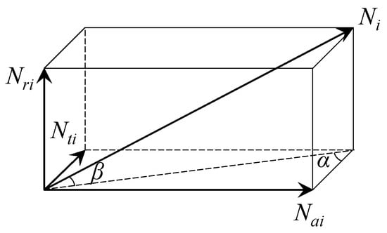
Figure 6.
Force decomposition of load force.
3. Friction Torque Model
In line with the structure of the PTRB, the external load is carried by dozens of small thread contacts between the threaded rollers and the bearing rings, which inevitably produces large amounts of friction torque [21]. In this section, we will define frictional torques based on their causes. To the best of our knowledge, each frictional torque component is described and derived in detail for the first time, enabling new options for further analysis.
Seeing that the PTRB is devised on the foundation of the PRS mechanism, the friction torque of the PTRB can be resolved in the same manner [22,23,24].The total friction torque of the PTRB is expressed as:
where , , , , and stand for the friction torques caused by material elastic hysteresis, roller spin-sliding, contact surface differential sliding, planetary-roller sliding, and viscous resistance, respectively. Further, each friction torque is generated from both the threaded roller-inner ring pair and the threaded roller-outer ring pair. The generation of the five different types of friction torques are analyzed below.
3.1. Friction Torque Caused by Material Elastic Hysteresis
The meshing between the threaded roller-ring pair results in the movement of the thread teeth. As stated in Hertzian contact theory, this contact shape can be simplified as an ellipse, which is presented in Figure 7. Elastic deformation occurs on the meshing thread tooth as the contact position of the two parts changes. Then, we deliver the major axis and the minor axis of the ellipse as:
where is the normal contact load; is the principal curvature summation of the contact point; and are parameters related to the principal curvature difference function.
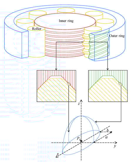
Figure 7.
Contact ellipse of threaded roller-inner/outer ring pair.
The computation of contact elastic deformation is given as:
where also involves the principal curvature difference function and is the equivalent elastic modulus of the contact pair, in line with Equation (2).
Hence, the central maximum compressive stress on the ellipse can be computed as:
together with the compressive stress of any point on the contact surface as:
where represents the coordinates within the ellipse.
The contact torque to the roller is derived via the integration of the elliptical contact surface, which is:
On account of the elastic hysteresis, the pressure distribution on the front- and rear-halves of the ellipse remains uneven. With the moving of the roller, the frictional torque working on the front half is greater than that of the rear half, and this difference is the energy loss caused by elastic hysteresis. On this occasion, we define an elastic hysteresis energy loss coefficient, , to characterize this energy loss. In this way, the friction torque on every single contact point caused by elastic hysteresis is:
Notably, on account of the actual direction and intensity of the load, the number of effective contact points varies. The total friction torque caused by material elastic hysteresis can be obtained by:
where stands for the effective contact point number of all meshing pairs.
3.2. Friction Torque Caused by Roller Spin-Sliding
In consideration of the working principle of the PTRB, a relative angular velocity exists within every meshing pair at all times. The relative angular velocity will inevitably lead to a spin-sliding, creating frictional torque. Supposing that the sliding friction coefficient is constant, the spin-sliding friction torque on the elliptical contact surface can be calculated based on the Jones raceway control theory [25], which is:
with representing the elliptic integral of the second kind:
where is the elliptical eccentricity.
Likewise, the roller spin-sliding friction torque on all threaded teeth of the threaded roller-inner/outer ring pairs are given by:
3.3. Friction Torque Caused by Differential Sliding
Similar to roller spin-sliding, contact surface differential sliding is generated due to the distinct rotating speeds of different working components. During operation, the outer ring of the PTRB is fixed whereas the inner ring rotates, driven by the shaft. We start with analyzing the differential sliding friction of the roller-inner ring pair. Let us assume that the inner ring angular speed is , roller spinning speed is , and the relative rotating speed is . For each contact point on the inner sliding raceway, its linear velocity is proportional to its distance to the inner ring axis . Similarly, the linear velocity of the contact point from the roller is proportional to the distance to threaded roller axis . When the linear velocities of the contact pair are equal, we have:
where stands for the pitch diameter of the PTRB.
Let be the intersection of the instantaneous axis and contact surface with equivalent linear velocities; see Figure 8. For the area above , the linear velocity of the contact point on the inner ring is larger than that of the contact point on the roller, and vice versa. As a result, we divide the relative sliding area into two parts, i.e., above and beneath .
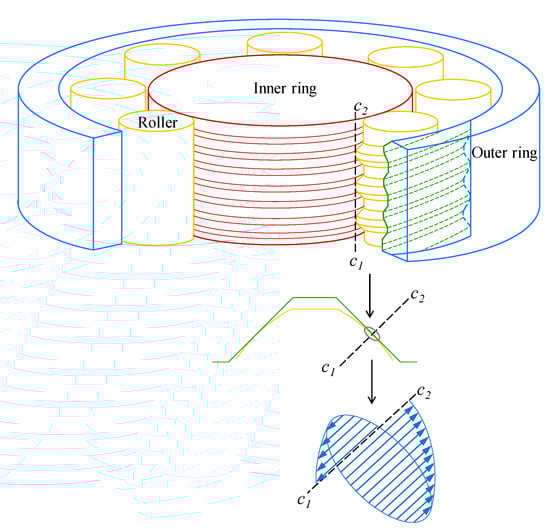
Figure 8.
Differential sliding of threaded roller-inner ring pair.
According to Equation (31), given the contact stress of a point in , the shear stress at this point is delivered as:
Thus, the friction torque of the area above is:
and the friction torque of the area beneath is:
with being the arm of shear stress [26,27,28]:
where and refer to the raceway radius of the inner ring and circular radius of the threaded roller, respectively.
From Equations (36) and (37), we have the friction torque of the roller-inner-ring pair as:
In the same manner, the friction torque of the roller-outer ring pair can also be computed, which is:
where
with representing the raceway radius of the outer ring.
The total friction torque caused by the differential sliding is:
3.4. Friction Torque Caused by Planetary-Roller Sliding
The pocket holes of both the rollers and planet carrier are circular. Sliding friction is thus generated during the self-spinning process. During dynamic equilibrium, the planetary-roller sliding friction is given by:
where is the lubricant kinematic viscosity; is both the width of the planetary carrier guide surface and depth of the pocket hole; ; is the diameter of the planetary carrier guide surface; and are the speeds of the planetary carrier and inner/outer ring, respectively; and represents the smaller diameter between the planetary carrier guide surface and rib guide surface, whereas refers to the larger diameter.
Then, the friction torques caused by planetary-roller sliding can be derived as:
3.5. Friction Torque Caused by Viscous Resistance
In a working PRS, the flow and viscosity of lubricating grease can also cause friction torque. The larger the amount of grease applied, the greater the generation of power consumption, which accelerates PTRB failure. In line with the Palmgren formula [29], the friction torque caused by viscous resistance for a PTRB is:
where stands for the coefficient related to bearing category and lubrication mode, is the lubricant kinematic viscosity, and is the rotating speed. The rotating speed is consistent for both contact pairs because of the threaded roller directly meshing with the inner/outer ring.
4. Analysis of Factors Affecting Friction Torque
To analyze the characteristics of PTRB friction torque, the optimal number of rollers isinvestigated, followed by studying the impacts of two major variables, i.e., external load and rotating speed. The mechanical structural parameters of the PTRB are collected from an in-service EMA and presented in Table 2.
Table 2.
PTRB configuration.
4.1. Effect of Roller Number on Friction Torque
The theoretical analysis reveals that the friction torque of the PTRB relates to the number of contact points, which are directly determined by the number of threaded rollers and the shape of thread teeth pairs. Seeing that the shape of thread teeth is fixed to hold a large external load, the thread teeth shape is fixed. Thus, only the roller number will be discussed in optimizing effectiveness.
Assuming that the rotating speed is 600 rpm and external load is 5000 N, the friction torques of different roller numbers are obtained; see Table 3.
Table 3.
Friction torque of different roller numbers.
As pointed out in Section 3, the friction torque components and are constant under constant speed conditions. On this occasion, , , and relate to both the external load and number of contact points. In contrast, for a fixed load applied to the PTRB, , , and all decrease as roller numbers increase. This is the same for total friction torque. That is, the increase in PTRB roller numbers can result in a smaller friction torque and better working properties. Considering the assembly space and machining complexity, the number of threaded rollers is set to 11, which is the maximum value for the PTRB structure.
4.2. Effect of Load on Friction Torque
According to the control variable method, the rotating speed is set to 600 rpm. The external loads are set to 5000, 10,000, 15,000, 20,000, 25,000, and 30,000 N. The speed-related friction torque components, i.e., and , together with their summation, are fixed values. We concentrate now on , , , as well as , varying with the external load. As presented in Figure 9, the relation between the total friction torque of the PTRB and load is generally nonlinear. Both the friction torque and its growth rate increase with higher external loads. The change in growth rate, also refers to as friction torque growth acceleration, tends to gradually stabilize. When the load reaches a certain value (15,000 N), the friction torque stays almost proportional to the load.
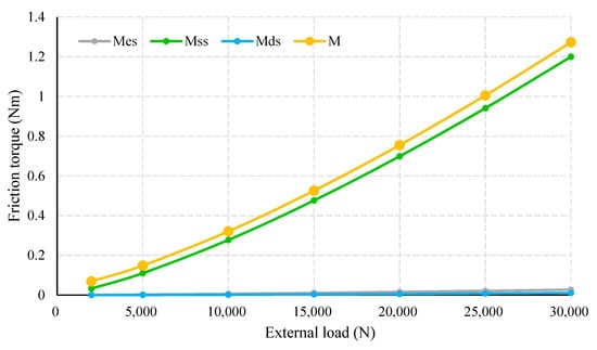
Figure 9.
Friction torque in relation to external load.
The proportion of distinguishing friction torque as load increases is shown in Figure 10. Obviously, consistently accounts for the largest amount, which rises dramatically with increases in load. The proportion of reaches 90% and approaches 100%, with the external load increasing over 14,000 N. In comparison, the contribution of and are minor. Despite growing with the load, the maximum percentages of and are only 2.2 and 0.9%, respectively.
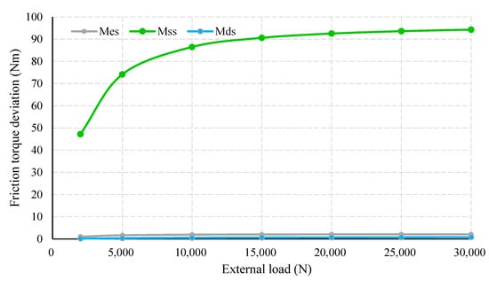
Figure 10.
Proportion of friction torque under distinguishing load.
Considering the working conditions of the PTRB, we also carried out an analysis on friction torque of variable loads, with rotating speeds of 1000, 2000, and 3000 rpm; see Table 4. Similar to the findings with 600 rpm speed, total friction torque had a positive increase in accordance with increasing external load. Specifically, steadily took up the highest proportion. Moreover, increases in speed among different evaluation settings also caused an overall decline in , , and .
Table 4.
Friction torque of variable loads and constant rotating speed.
4.3. Effect of Rotating Speed on Friction Torque
Likewise, to evaluate the impact of rotating speed on friction torque, the rotating speeds ranged from 200 to 2000 rpm, with an interval of 200, whilst the load is 5000 N. Because and are speed-related variables, the friction torque with respect to different rotating speeds are given in Figure 11.
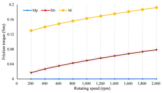
Figure 11.
Friction torque in relation to rotating speed.
In general, the total friction torque increases almost linearly with increasing rotating speed, whereas its growth rate decreases. In contrast, has a linear relationship with rotating speed, which has little variation. Furthermore, the proportion of and in is presented in Figure 12. Clearly, the proportion of far exceeds that of . According to Figure 11 and Figure 12, one can easily see that both the amount and proportion of rapidly increase to conform to the rotating speed. The proportion of exceeds 40% of total friction torque whilst rotating speed is 1800 rpm. Nevertheless, the friction torque caused by planetary-roller sliding makes a marginal contribution, with its maximum proportion being less than 0.17%. Speed-related friction torque components with a given external load are also presented. According to Table 5, for a set of rotating speeds, an increase in load inevitably results in an increase in total friction while both and have identical values. Thus, the proportion of speed-related friction torques drops, which is the same case as that shown in Table 4.
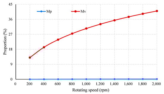
Figure 12.
Friction torque in relation to rotating speed.
Table 5.
Friction torque of variable rotating speeds and constant load.
5. Experiments
5.1. Experimental Setup
Experiments on PTRB friction torque in real working conditions are conducted on the verification platform. A photograph of the experimental setup is shown in Figure 13. To test friction torque, a prototype of the PTRB is manufactured and installed on the test rig. According to Figure 13, a hydraulic pressure stand supplies oil to the loading process. Specifically, as pointed out in Section 3, the PTRB is lubricated with grease during operation, and the rise in temperature considerably affects the generation of friction torque. An air cooler is thus employed to moderate the temperature of the PTRB. Both the control and data acquisition modules are integrated into a host computer. The former controls workflow and the latter records signals from sensing elements.
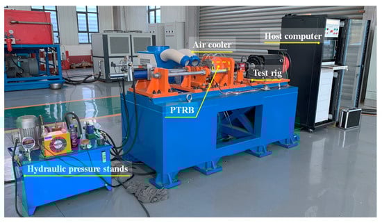
Figure 13.
Experimental setup.
A schematic of the PTRB test rig is exhibited in Figure 14. The test PTRB is embedded into a support base to keep location constant. The variations in rotating speed is delivered to the PTRB via a servo motor and transmission rod. The external load is applied by using loading cylinders. In this experiment, the external load is generally divided into axial and radial load. With respect to the EMA working principle, the axial load is referred to as the aiding load.Accordingly, an axial and radial loading cylinder, together with two tension-compression sensors detecting the outputs, are utilized. Both the motor and cylinders are controlled by the control module. Moreover, two more PTRBs of the same type are taken as accompanying bearings to support the shaft. These three PTRBs are established so closely that the forces of the three bearings could be considered identical. The friction torque of the working PTRB is detected using a torque sensor and sent to the data acquisition module. Theoretically, the sensing signals of the torque sensors involved only the friction torques of the three PTRBs. However, additional parasitic friction torque can be generated by moment of inertia and grease. In this experiment, all friction torques are measured if the rotation speed is constant. Furthermore, a running-in test is also performed before experiments to prevent the instability of grease at a low temperature. Forced refrigeration measures are adopted to retain the temperature of the bearing around 55 °C. Major components, as well as their parameters, are listed in Table 6.
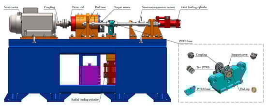
Figure 14.
Test rig.
Table 6.
Major components of experiment.
The friction torque dynamics of the PTRB is presented in Figure 15. During the initial stage, an overshoot is caused by both the arising inertia and load application. With the system adjustment, friction torque is measured within the stable actuation process. Then, the test PTRB is switched to the next working mode, and so on. Notably, the rotating speed is set to 200–2000 rpm whilst the external load is set to 2000–30,000 N. The following results are discussed in the context of this working condition.
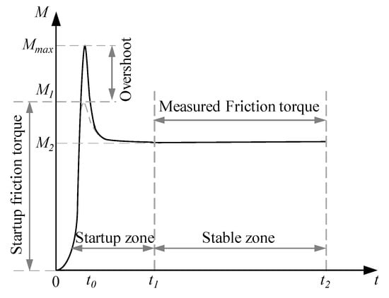
Figure 15.
Dynamics of friction torque.
5.2. Main Results
In this experiment, the external loads and rotating speeds of the PTRB are set corresponding to the analyses of friction torque. The theoretical friction torques, based on the friction torque model, are computed in advance. The friction torques of both radial-and axial-directional loads are recorded based on an identical theoretical value under different working conditions. Notably, the measuring range of the torque sensor is5 Nm and its accuracy is 1% full scale. Measurement error is restricted within 0.005 Nm, which is negligible to the measured results.
Figure 16 shows the results of measured friction torques in comparison with the theoretical friction torque, as well as the deviations. With a given rotating speed of 600 rpm, actual friction torques showed the same trends as the theoretical values. Notably, the friction torque of radial load fit the computation model better than that of axial load. The maximum deviation ratio of radial-load-friction-torque is only 12.7%, which gradually declines with the increase of load. In comparison, there is a considerable gap between the axial-load-friction-torque and its theoretical value, and its maximal proportion reached 42.6%. A possible explanation is that the actual external load applied to the PTRB is uneven in the axial direction. More concretely, the axes of the axial loading cylinder and PTRB could not be aligned during system assembly.
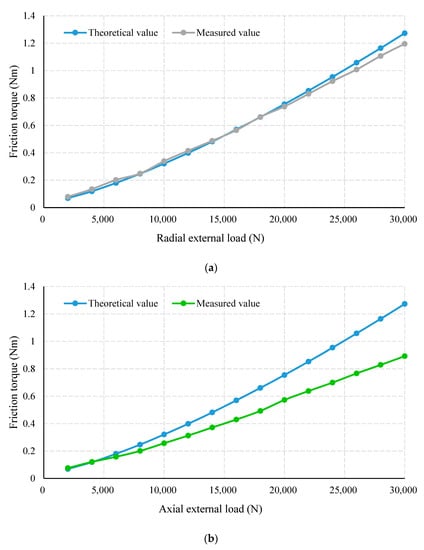
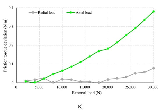
Figure 16.
Measured friction torque of variable external loads and constant rotating speed: (a) friction torque of radial external load; (b) friction torque of axial friction torque; (c) absolute deviation of friction torque.
On the other hand, given a constant load of 5000 N, the friction torques varying with rotating speeds are also obtained; see Figure 17. Likewise, the external loads of radial and axial directions are separately applied. With an increase in rotating speed, the measured friction torques under both radial and axial load showed a similar growth trend with the theoretical values. The deviations of both conditions are comparable, with maximum proportions against the theoretical friction torque being 12 and 13%, respectively.
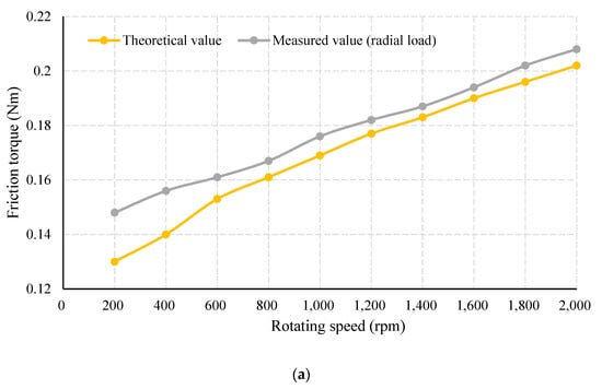
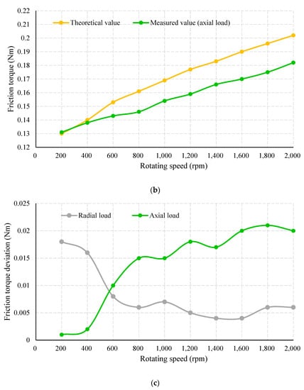
Figure 17.
Measured friction torque of variable rotating speeds and constant external load: (a) friction torque of radial external load; (b) friction torque of axial external load; (c) absolute deviation of friction torque.
Under the working condition of having a 200–2000 rpm rotating speed and 2000–30,000 N reverse load, measured friction torque fits the theoretical friction torque model to a great extent. That is, the computed curve of the friction torque generally covered the actual values under both variable-speed-constant-load and variable-load-constant-speed conditions. The average relative errors of the four distinctive working conditions are given in Figure 18. It is evident that the outcome of radial load outperforms that of axial load in both evaluation settings. This issue can be further resolved by improving coaxiality between the axial loading cylinder and PTRB. Because measured friction torque considerably conforms with theoretical friction torque, it is reasonable to expect greater robustness and higher precision using the friction torque computation model, which is validated by our findings.
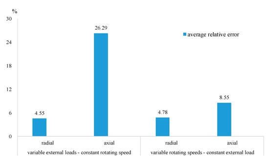
Figure 18.
Average relative error of different conditions.
6. Conclusions
In this work, the friction torque of the PTRB is comprehensively studied for EMA applications. To start, the structure of the PTRB and its working principle are depicted. A theoretical model of friction torque is established by combining Hertzian contact theory and structural characteristics. The total friction torque is subdivided into five categories. These formulas are derived from the different causes of friction torque. Further, our analysis of friction torque could identify the impacts of external loads and rotating speeds. We observe the variation in each component of friction torque, as well as their proportions under different conditions. Experiments are conducted according to the friction torque analysis results. Experimental results reveal the working performance of our friction torque model and the analysis.We set rotating speeds between 200 and 2000 rpm and reverse external loads from 5000 to 30,000 N. In this way, a precise mathematical model of friction torque with speeds of 200–2000 rpm, reverse loads of 2000–30,000 N, and a temperature restricted to 55 °C is now accessible.
In comparison to theoretical values, the measured friction torques fit well with the friction torque computation model. The deviations between theoretical and measured friction torque validate the technical efficacy of the friction torque model.
Author Contributions
Conceptualization, L.L. and Y.G.; methodology, C.Z. and L.L.; validation, C.Z. and Y.B.; formal analysis, L.L.; investigation, L.L. and Y.F.; resources, Y.G. and Y.F.; data curation, J.Z. and Y.N.; writing—original draft preparation, C.Z.; writing—review and editing, L.L.; supervision, Y.G. and Y.F.; project administration, Y.G. and L.L.; funding acquisition, Y.G. All authors have read and agreed to the published version of the manuscript.
Funding
This research is a general project supported by the Shanxi Province Key R & D Program International Science and Technology Cooperation Project of China (201903D421008) and Basic Research Project of Shanxi Province of China (20210302123039).
Institutional Review Board Statement
Not applicable.
Informed Consent Statement
Not applicable.
Data Availability Statement
Data sharing not applicable.
Conflicts of Interest
The authors declare no conflict of interest.
References
- Qiao, G.; Liu, G.; Shi, Z.; Wang, Y.; Ma, S.; Lim, T.C. A review of electromechanical actuators for More/All Electric aircraft systems. Proc. Inst. Mech. Eng. Part C J. Mech. Eng. Sci. 2018, 232, 4128–4151. [Google Scholar] [CrossRef] [Green Version]
- Quattrocchi, G.; Iacono, A.; Berri, P.C.; Vedova, M.D.L.D.; Maggiore, P. A New Method for Friction Estimation in EMA Transmissions. Actuators 2021, 10, 194. [Google Scholar] [CrossRef]
- Fu, X.; Liu, G.; Ma, S.; Tong, R.; Lim, T.C. A Comprehensive Contact Analysis of Planetary Roller Screw Mechanism. J. Mech. Des. 2016, 139, 012302. [Google Scholar] [CrossRef]
- Fu, X.; Liu, G.; Ma, S.; Tong, R.; Lim, T.C. Kinematic Model of Planetary Roller Screw Mechanism with Run-Out and Position Errors. J. Mech. Des. 2018, 140, 032301. [Google Scholar] [CrossRef]
- Ma, S.; Liu, G.; Tong, R.; Zhang, X. A New Study on the Parameter Relationships of Planetary Roller Screws. Math. Probl. Eng. 2012, 2012, 340437. [Google Scholar] [CrossRef]
- Ma, S.; Liu, G.; Tong, R.; Fu, X. A Frictional Heat Model of Planetary Roller Screw Mechanism Considering Load Distribution. Mech. Based Des. Struct. Mach. 2015, 43, 164–182. [Google Scholar] [CrossRef]
- Jiang, X.; Wang, B. Analysis on the development of future aero engine technology. Aeronaut. Sci. Technol. 2010, 2, 10–12. [Google Scholar]
- Nguyen, N.; Ong, V.; Villanueva, A.; Hsu, D.; Nguyen, N.; Dhillon, N.; Shankar, P. Design and testing of solid propellant rockets towards NASA Student Launch and Intercollegiate Rocket Engineering Competitions. In Proceedings of the 2018 Joint Propulsion Conference, Cincinnati, OH, USA, 9–11 July 2018. [Google Scholar] [CrossRef]
- Zheng, S.; Fu, Y.; Pan, J.; Li, L.; Wang, D. An In-Depth Study on Load Distribution Characteristics of the Planetary Threaded Roller Bearing. Math. Probl. Eng. 2020, 2020, 9593051. [Google Scholar] [CrossRef]
- Zheng, S.; Fu, Y.; Wang, D.; Pan, J.; Li, L.; Wang, J. A Novel Planetary Thread Roller Bearing: Design and Analysis of Load Characteristic. J. Mech. Des. 2021, 143, 064501. [Google Scholar] [CrossRef]
- Zhou, X.; Zhou, F.; Huang, J.; Ji, J.; Zhong, M.; Yan, Z.; Zheng, B. Friction and wear properties of a new plastic rubber water-lubricated bearing material. In Proceedings of the 2017 4th International Conference on Transportation Information and Safety (ICTIS), Banff, AB, Canada, 8–10 August 2017; pp. 1022–1027. [Google Scholar]
- Wang, F.; Zhou, C.; Zheng, L.; Zhang, H. Improvement of the corrosion and tribological properties of CSS-42L aerospace bearing steel using carbon ion implantation. Appl. Surf. Sci. 2017, 392, 305–311. [Google Scholar] [CrossRef]
- Qin, D.; Xie, L. Modern Handbook of Mechanical Design, 2nd ed.; Chemical Industry Press: Beijing, China, 2019. [Google Scholar]
- Giangrande, P.; Galassini, A.; Papadopoulos, S.; Al-Timimy, A.; Calzo, G.L.; Degano, M.; Galea, M.; Gerada, C. Considerations on the Development of an Electric Drive for a Secondary Flight Control Electromechanical Actuator. IEEE Trans. Ind. Appl. 2019, 55, 3544–3554. [Google Scholar] [CrossRef]
- Li, C.; Xia, X. Uncertainty Evaluation of Bearing Performance Based on Gray Bootstrap Method. In Proceedings of the 2018 3rd International Conference on Computer Science and Information Engineering, Sanya, China, 22–24 October 2018; pp. 403–408. [Google Scholar]
- Battez, A.H.; Fernandes, C.M.; Martins, R.C.; Graça, B.M.; Anand, M.; Blanco, D.; Seabra, J.H. Two phosphonium cation-based ionic liquids used as lubricant additive. Part II: Tribofilm analysis and friction torque loss in cylindrical roller thrust bearings at constant temperature. Tribol. Int. 2017, 109, 496–504. [Google Scholar] [CrossRef]
- Wang, J.; Wang, J.; Wang, X.; Huang, Y. A Threaded Roller Planetary Bearing. CN208057692U, 6 November 2018. [Google Scholar]
- Ravelo, B.; Peyret, N.; Penas, O.; Davin, T. Multiphysics Analysis of Hemispherical Bulk Conductor Hertzian Contact Under Uniaxial Mechanical Load. IEEE J. Multiscale Multiphysics Comput. Tech. 2019, 4, 171–179. [Google Scholar] [CrossRef]
- Armendariz, J.; Treesatayapun, C.; Baltazar, A. Development of an estimated force feedback controller based on hertzian contact and ultrasound. In Proceedings of the 2010 IEEE International Workshop on Robotic and Sensors Environments, Phoenix, AZ, USA, 15–16 October 2010; pp. 1–6. [Google Scholar]
- Lisowski, F. Numnerical Computation of Stresses and Deformations in the Planetary Roller Screw Components. Tech. Trans. 2015, 7, 141–148. [Google Scholar]
- Qiao, G.; Liu, G.; Ma, S.; Shi, Z.; Lim, T.C. Friction Torque Modelling and Efficiency Analysis of the Preloaded Inverted Planetary Roller Screw Mechanism. In Proceedings of the ASME 2017 International Design Engineering Technical Conferences and Computers and Information in Engineering Conference, Cleveland, OH, USA, 6–9 August 2017; pp. 1–9. [Google Scholar] [CrossRef]
- Du, C.; Liu, G.; Qiao, G.; Ma, S.; Cai, W. Transient thermal analysis of standard planetary roller screw mechanism based on finite element method. Adv. Mech. Eng. 2018, 10, 1–10. [Google Scholar] [CrossRef]
- Zhang, W. Model and Method for Calculating the Load Distribution of the Thread Teeth of Planetary Roller Screw Pairs; Northwestern Polytechnical University: Xi’an, China, 2017. [Google Scholar]
- Qiu, M.; Chen, L.; Li, Y. Principle and Application of Bearing Tribology; Defense Industry Press: Beijing, China, 2012. [Google Scholar]
- Jones, A.B. Ball Motion and Sliding Friction in Ball Bearings. J. Basic Eng. 1959, 81, 1–12. [Google Scholar] [CrossRef]
- Houpert, L. Rolling Bearing Torque. In Encyclopedia of Tribology; Springer: Boston, MA, USA, 2013; pp. 2891–2899. [Google Scholar]
- Houpert, L. Numerical and analytical calculations in ball bearings. In Proceedings of the 8th European Symposium, Toulouse, France, 29 September–1 October1999; pp. 1–9. [Google Scholar]
- Olaru, D.; Puiu, G.C.; Balan, L.C.; Puiu, V. A New Model to Estimate Friction Torque in a Ball Screw System. In Product Engineering; Springer: Dordrecht, The Netherlands, 2005; pp. 333–346. [Google Scholar]
- Zaretsky, E.V. A. Palmgren Revisited, A Basis for Bearing Life Prediction. Lubr. Eng. 1998, 54, 18–23. [Google Scholar]
Publisher’s Note: MDPI stays neutral with regard to jurisdictional claims in published maps and institutional affiliations. |
© 2022 by the authors. Licensee MDPI, Basel, Switzerland. This article is an open access article distributed under the terms and conditions of the Creative Commons Attribution (CC BY) license (https://creativecommons.org/licenses/by/4.0/).