Article

Switching Model Predictive Control for Thin McKibben Muscle Servo Actuator

by
Mohd Akmal Mhd Yusoff
1,2,
Ahmad Athif Mohd Faudzi
3,4,*,
Mohd Shukry Hassan Basri
2,
Mohd Fuaad Rahmat
3,
Mohd Ibrahim Shapiai
1,4 and
Shahrol Mohamaddan
5
1
Malaysia-Japan International Institute of Technology, Universiti Teknologi Malaysia, Jalan Sultan Yahya Petra, Kuala Lumpur 54100, Malaysia
2
Engineering Research Centre, Malaysian Agricultural Research and Development Institute (MARDI) Headquarters, Persiaran MARDI-UPM, Serdang 43400, Malaysia
3
School of Electrical Engineering, Faculty of Engineering, Universiti Teknologi Malaysia, Skudai, Johor Bahru 81310, Malaysia
4
Centre for Artificial Intelligence and Robotics (CAIRO), Universiti Teknologi Malaysia, Jalan Sultan Yahya Petra, Kuala Lumpur 54100, Malaysia
5
Department of Bioscience and Engineering, College of Systems Engineering and Science, Shibaura Institute of Technology, Saitama 337-8570, Japan
*
Author to whom correspondence should be addressed.
Actuators 2022, 11(8), 233; https://doi.org/10.3390/act11080233
Submission received: 16 July 2022 / Revised: 10 August 2022 / Accepted: 11 August 2022 / Published: 15 August 2022

Abstract

:
Dynamic characteristics and control of thin McKibben muscle (TMM) have not yet been fully investigated, especially on the translational antagonistic pair system. Therefore, the objective of this study is to propose a Switching Model Predictive Control (SMPC) based on a Piecewise Affine (PWA) system model to control a translational antagonistic-pair TMM servo actuator. A novel configuration enables the servo actuator to achieve a position control of 40 mm within a small footprint. The result shows that the feedback system gives minimal steady-state errors when tracking staircase and setpoint references ranging from 0 to 3.5 cm. The controller also produces better transient and steady-state responses than our previously developed Gain-scheduled Proportional–Integral–Derivative (GSPID) controller. The evidence from this study suggests that a predictive control for a TMM servo actuator is feasible.

1. Introduction

Many compliant and soft robotic arms have been developed using pneumatic muscle actuator (PMA) or also known as McKibben muscle (MM) because of its similarity to human muscle in terms of compliance characteristics and contraction properties. These muscles are usually powered by mechanical air compressor, but some researchers have explored the possibility of using non-mechanical micropumps such as electrohydrodynamic pumps [1]. Due to its high output force, conventional MM is preferred over thin McKibben muscle (TMM) in applications needing high force in an unconfined environment. TMM, on the other hand, is better suited to robotic applications where space is limited due to its flexibility and small weight. For example, snake-like manipulator has been developed by Faudzi et al. [2] using TMMs attached to a thin bendable plastic. A more complicated approach has been taken by Pang et al. [3] where they used springs and flange plates with TMMs to guide the manipulator. Similar structure has been used by Liu et al. [4] with the difference being the springs replaced by internal TMMs set. Another recent example of TMM-based continuum manipulator can be seen in Mohamed et al. [5].
Precise positioning control could expand TMM’s usability, for example into surgical robots [6]. However, MMs, in general, are known to have nonlinear response and hysteresis. Therefore, using them for position control is challenging. Nonlinear control methods are preferred in applications requiring a large range of operation and high-speed motions. One of them is sliding mode control [7,8,9,10]. It is a type of robust controller that takes the uncertainty of model parameters and system disturbances into consideration. It is also based on the assumption that first order system is easier to control than higher order system. Another one is the adaptive controller [11,12,13], whose parameters vary throughout the process and are used in systems with uncertain parameters. Even though the robust controller can also be used for such systems, the adaptive controller is better when the unknown parameters are constant or vary slowly over time. However, its drawback compared to robust controller is its inability to deal with disturbances and unmodeled dynamics.
Another popular control method is the artificial intelligence (AI)-based control, which builds the controller’s model using AI such as neural network (NN) and fuzzy logic. NN is a series of algorithms, modeled roughly after the animal brain, that is designed to recognize patterns. Among the applications of NN are implementing gain scheduling of the Proportional–Integral–Derivative (PID) controller [14], determining the model parameters in the adaptive controller [15,16], and acting as the controller itself through the use of inverse dynamics [17]. On the other hand, fuzzy logic is a set of degrees of truth, modeled after the human reasoning, that is designed to represent knowledge [18]. Thus, the use of fuzzy controllers is achieved through inverse dynamics, as can be seen in works by Leephakpreeda [19], And and Ahn [20], and Chandrapal et al. [21]. Although these methods are promising, they require plenty of data gathering and training.
In many robotic applications, MMs and TMMs are used in antagonistic pair configuration [9,10,11,12,13,22,23,24,25] whereby at any time, a set contracts and another set relaxes. Compared to single-acting arrangement [15,26,27,28,29], it is more challenging to control because two different contraction modes need to be handled simultaneously. Switching linear controllers such as Switching Model Predictive Control (SMPC) [30,31,32] and Gain-scheduled Proportional–Integral–Derivative (GSPID) [28] have been used to control such systems. Being basically a combination of linear controllers, they are simpler to design compared to other nonlinear controllers. However, the existing literature focuses on conventional MMs, which have different characteristics than TMM such as the absence of slack and significantly higher mass. A thorough search of the relevant works of literature yielded no related article on TMM.
There are typically two ways that an antagonistic pair configuration is realized: a rotational system and a translational system. Compared to rotational systems [8,16,28,33,34,35,36,37], translational systems [38,39,40] of MM, let alone of TMM, have not been studied as much. In addition, in the works on translational systems, other researchers have only achieved a maximum position control of 15 mm and 6.4 mm for a maximum pressure of 0.45 and 0.5 MPa, respectively, on their translational systems [7,39]. Table 1 summarizes the contributions of this paper with its main references.

2. Materials and Methods

This section is comprised of five parts. In the first part, the system under study and its PWA model are explained. Then, in the second part, the SMPC is detailed out. In the third part, the experiment setup is presented. In the last two parts, the stability of the controller is discussed.

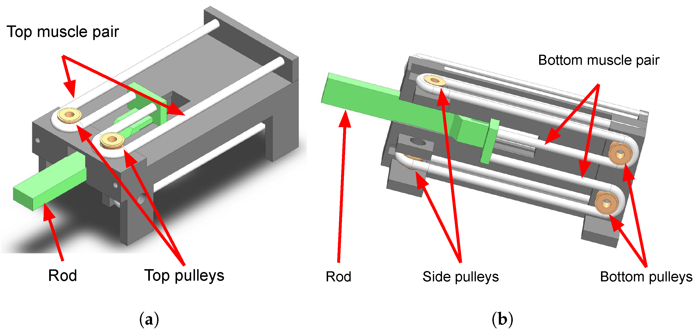
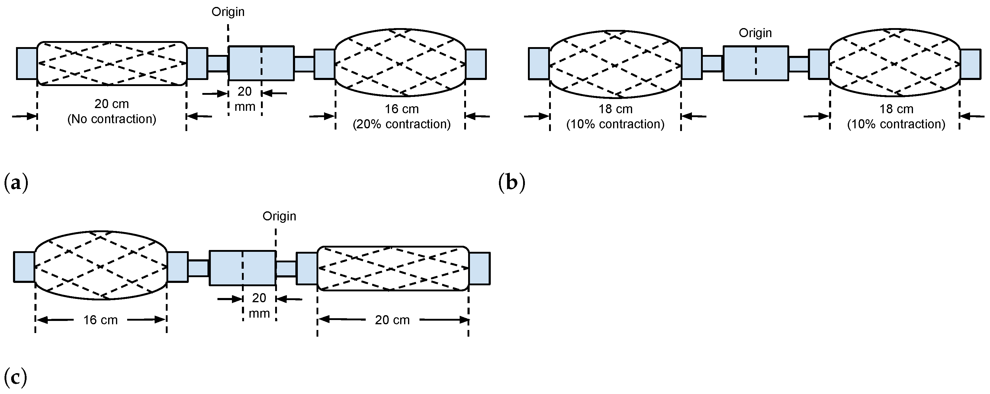
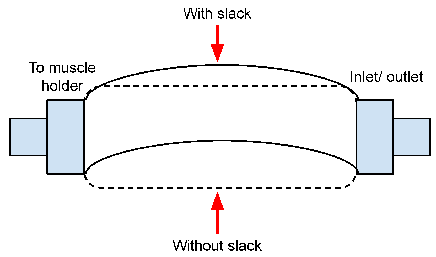
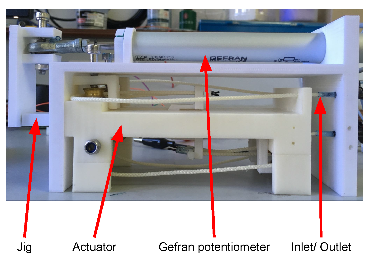
2.1. TMM Servo Actuator and Its PWA Model

The prototype’s drawings are shown in Figure 1. It uses commercial TMMs [41] with an outer-tube diameter of 1.8 mm and operating range of 0–0.5 MPa. The muscle’s specifications are listed in Table 2 based on [41]. The antagonistic pair muscles are placed in different elevations. This configuration is necessary to realize a maximum displacement in the horizontal plane within a small footprint. The actuator uses two valves to control the top and bottom muscle pairs separately.
The main difference between the configuration used in this study and that used by other researchers [7,39] is the use of pulleys and the placement of the antagonistic pair muscles on different elevations and in parallel. This configuration is necessary to maximize the rod displacement in the horizontal plane within a small footprint. Other researchers placed the muscles on the same elevation, to the the left and the right of the load, without the use of pulley. Such sonfiguration entails that for a position control of 40 mm, the length of the setup has to be more than 36 cm, as shown in Figure 2. With the use of the pulley–different elevations–parallel system, the prototype is only about 10 cm.
Another difference in this configuration is the use of TMM instead of conventional PAM. Whereas conventional PAM is rigid, TMM is flexible and has slack. The slackness causes a passive contraction range whereby its contractile force does not affect the load displacement, as described in Figure 3 and Figure 4.
The servo actuator is modelled as a multiple-input single-output (MISO) system. Its inputs are air pressure into the top McKibben muscle pair, P a , and bottom muscle pair, P b , whereas its output is the rod displacement, x. The contractile force, F, from a single muscle acting on the rod can be described using Schulte’s formula [43]
F = π D 0 2 P 4 3 cos 2 θ 1
where D 0 , P, and θ are the maximum muscle diameter, applied pressure, and muscle’s braid angle. Since D 0 is a constant, at the same pressure, F depends on θ alone.
Therefore, based on Equation (1), F is maximum at the start of contraction ( θ = θ 0 ). This force moves the rod. As illustrated in Figure 5, as the muscle contracts, θ increases and F decreases. When the muscle is fully contracted, F equals to zero and the rod stops moving.
Whereas the previous discussion is on the static model of a TMM, which gives a good background on its behavior, the dynamic model is more useful in fully explaining what is happening during transients, such as during the start of a system. The dynamic model, as illustrated in Figure 6, has been derived and explained in detail in our previous work [42]. Furthermore, the piecewise affine (PWA) system has been used to represent the model, which enables a switching controller to be developed for the actuator. Some of the paper’s important results are republished here to aid in understanding PWA and its role in the development of the SMPC.
The state space model of the system for extension operation near the mth operating point x m o p is given by
x ˙ x ¨ = 0 1 Q m M D m M x x ˙ + 0 T m M δ P a + 0 Q m M x m o p
and its compact form by
x c ˙ = A c m x c + B c m δ P a + f c m y c = C c m x c
where x c = x 1 x 2 = x x ˙ X a R 2 , y = x , and δ P a P a R , with X a and P a are the sets of state and input pressure containing the operating points x m o p and P a m o p , respectively, and A c m , B c m and C c m are matrix variables of system, input and output given by
A c m = 0 1 K m M 2 α P a m o p l a M 1 x m o p l a D m M ,
B c m = 0 1 M α 1 x m o p l a 2 + β ,
C c m = 1 0 0 1
and f c m is the affine term given by
f c m = 0 K m x m o p M + 2 α P a m o p x m o p l a M 1 x m o p l a .
On the other hand, the state space model of the system for retraction operation near n-th operating point x n o p is given by
x ˙ x ¨ = 0 1 Q n M D n M x x ˙ + 0 T n M δ P b + 0 Q n M x n o p T n P b n o p M
and its compact form by
x c ˙ = A c n x c + B c n δ P b + f c n y c = C c n x c
where
A c n = 0 1 K n M 2 α P b n o p l b M 1 x max x n o p l b D n M
B c n = 0 1 M α 1 x max x n o p l b 2 + β ,
C c n = 1 0 0 1 ,
f c n = 0 K n x n o p M + 2 α P b n o p x n o p l b M 1 x max x n o p l b .

2.2. Tracking MPC

The system at the bth mode can be represented by the following discrete-time linear time invariant function
x c k + 1 = A c b x c k + B c b u k + f b y c k = C c b x c k
where A c b = A c 11 b A c 12 b 0 A c 21 b A c 22 b 0 0 0 I , B c b = B c 11 n B c 12 b B c 21 n B c 22 b 0 0 and u k = P a k P b k .
To simplify the notation, the active-mode notation, b will be dropped in the subsequent discussion. Augmenting the state vector in Equation (14) to include affine term f yields
x k + 1 = A x k + B u k y k = C x k
To simplify the discussion to follow, prediction horizon and control horizon is assumed to be of the same value. The general finite horizon cost function from time instance 0 to N p that depends on the initial state x 0 and input sequence U 0 N p = u 0 , , u N p 1 for an optimal controller is then given by
J 0 I x 0 , U 0 N p = p x N p + i = 0 N p 1 q x i , u i
where N p is the prediction horizon, p ( x N p ) is the terminal cost function, q ( x i , u i ) is the stage cost function, and x i is the state vector at time i resulting from the input sequence U 0 N p applied to the system model
x i + 1 = A x i + B u i
starting at x 0 .
Model Predictive Control (MPC) uses the same cost function (Equation (16)) calculation, but instead of a one-time operation at the initial time, the calculation is repeated at every time instance k. Since Equation (17) predicts at k = 0 what the future state vector would be, the future state and output predicted at time k can be written as
x k + i + 1 | k = A x k + i | k + B u k + i | k y k + i | k = C x k + i | k
where x k + i | k is the ith state predicted at k and u k + i | k is the ith input computed at k. The finite horizon cost function at time k for MPC can then be defined as
J k k + N p k x k , U k k + N p k = p x k + N p k + i = 0 N p 1 q x k + i k , u k + i k
where U k k + N p = u k , , u k + N p 1 is the calculated input sequence. If a quadratic cost function is used, Equation (19) becomes
J k k + N p k x k , U k k + N p k = x N p P x N p + i = 0 N p 1 ( x i Q x i + u i R u i ) .
where P is the terminal weight, Q is the state weight, and R is the input weight. The MPC optimization problem at every time instance k is then: given x k , find U k k + N p k , which minimizes Equation (20) subject to constraints, that is
min U k k + N p | k x N p P x N p + i = 0 N p 1 ( x i Q x i + u i R u i ) subject to x k + i + 1 | k = A x k + i | k + B u k + i | k E u s e .
MPC then uses only the first control signal, u k = K x k , and resolves the optimization problem, Equation (21) at the next time instance, k + 1 .
The servo actuator is to track a reference trajectory, r; therefore, an MPC has been designed with the main objective of minimizing the error, e, between r and the output, y. The cost of implementing such a controller consists of the performance cost, which depends on P and Q, and the effort cost, which depends on R, and by tuning the weights, the balance between the two costs can be specified. In addition, the controller needs to work within certain constraints, such as the state and input inequality constraints, i.e., x m i n x x m a x and u m i n u u m a x . The cost problem of the tracking controller is then defined as [44]
min ( y k + N P | k r k + N P | k ) P ( y k + N P | k r k + N P | k ) + i = 0 N P 1 [ ( y k + i | k r k + i | k ) Q ( y k + i | k r k + i | k ) + Δ u k + i | k R Δ u k + i | k ] s . t . y min y k + i | k y max , i = 1 , , N p u min u k + i u max , i = 0 , , N p Δ u min Δ u k + i Δ u max , i = 0 , , N p u k + i = 0 , i N p x k + i + 1 | k = A x k + i | k + B [ u k + i 1 | k + Δ u k + i ] y k + i | k = C x k + i | k

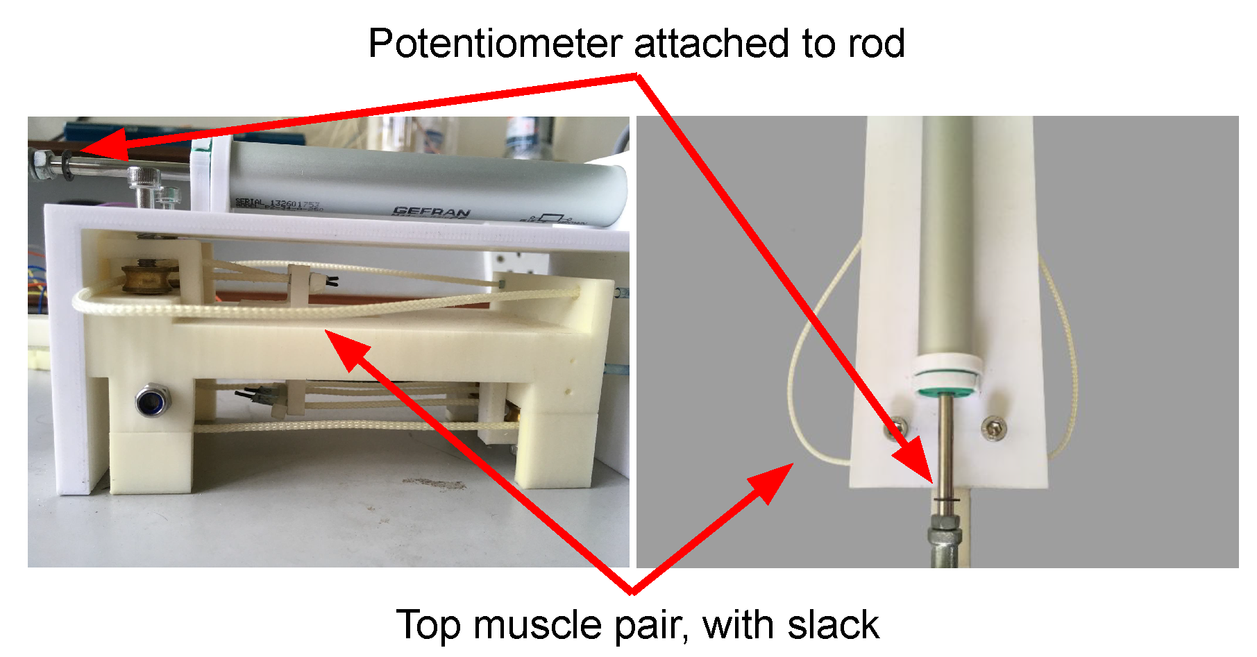
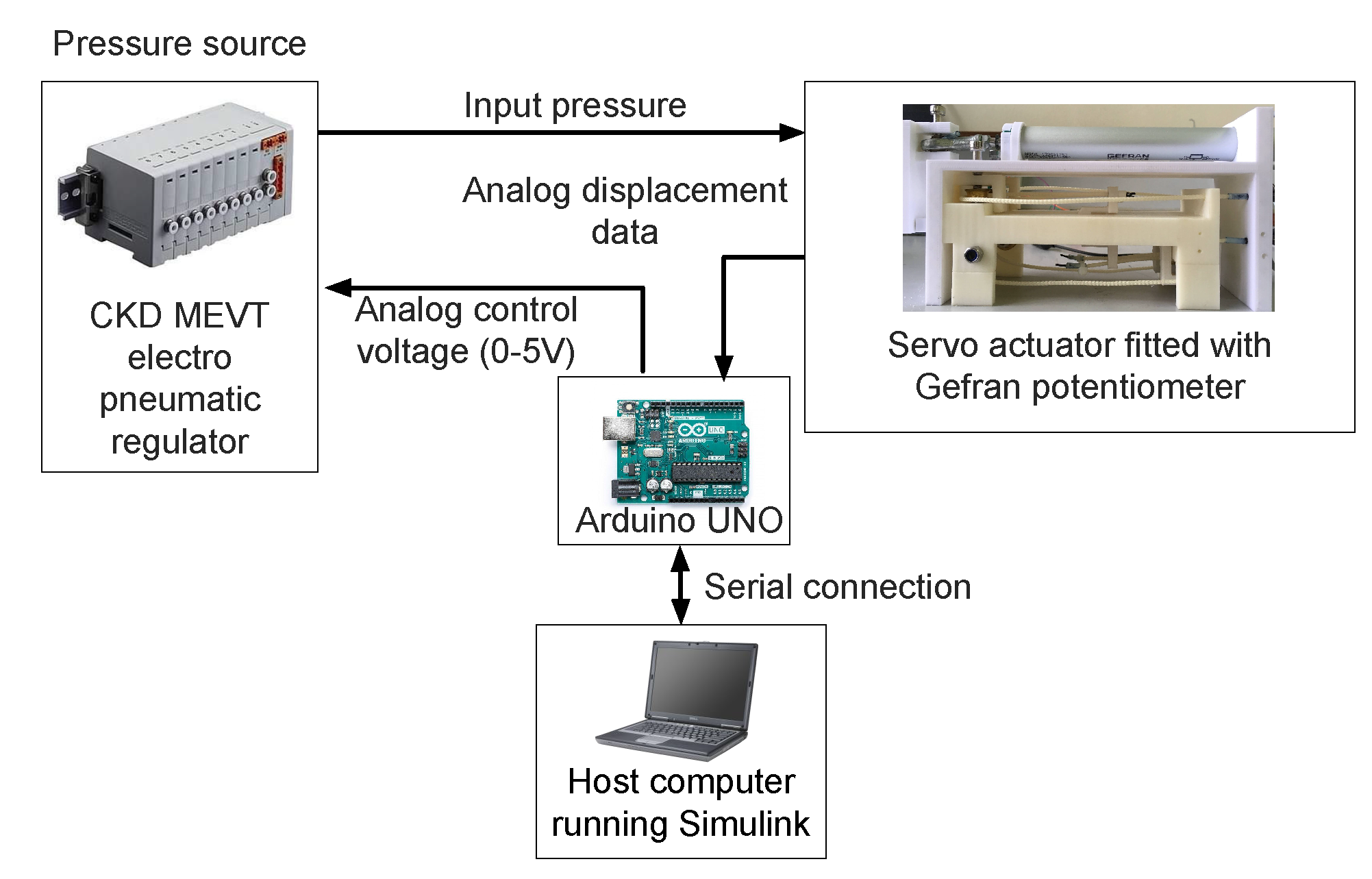
2.3. Experiment Setup

The prototype fitted with a Gefran® potentiometer is shown in Figure 7, and an overview of the experiment setup is shown in Figure 8. The detail of the experiment setup can be referred to [45]. A Gefran PZ-34-A-250 linear potentiometer is used to measure the rod position, whereas the acceleration is obtained by using a filtered derivative of the measured position with a time constant of 0.03.
The overall SMPC control system is shown in Figure 9. The controller was developed using Hybrid Toolbox [44], Multi-Parametric Toolbox 3.0 [46], YALMIP [47] and HYSDEL [48]. A feed forward controller was used in addition to the MPC controller to minimize the settling time. In addition, it ensures that maximum displacement is achieved. A lookup table, Table 3, is used to determine the value of the feedforward signal. The mapping of the table depends on reference signal and forward–reverse switch.

2.4. Stability of Finite Horizon Optimal Controller

The stability of a discrete-time system can be checked using Jury stability criterion. The system is stable if the eigenvalues of the closed-loop system is inside the unit circle. Given a plant as in Equation (15) with a state-feedback controller, stability is determined by solving
det [ λ I A c l ] = 0
for eigenvalues, λ with A c l = A B K and K being the gain. In MATLAB, Equation (23) is solved using the command e i g ( A c l ) .
For a finite horizon optimal controller such as MPC, the value of K, and hence the eigenvalues, depend on the prediction horizon, N p . It is well-known that asymptotic stability of a predictive controller is ensured with an infinite N p . However, instability is not ensured with small N p . James B. Rawlings et al. [49] shows that a short N p might produce closed-loop eigenvalues outside of the unit circle. Therefore, in general, MPC stability is not guaranteed [50].
Several methods have been proposed to guarantee the stability of MPC, as discussed in [51]. In this study, a terminal-equality constraint whereby the terminal cost F ( . ) and terminal constraint x ( N ) X f satisfy F ( x ) 0 and X f = { y s p } was adopted to guarantee the MPC’s stability. In Hybrid Toolbox, this is achieved by setting Q.xN to zero, and limits.Sx and limits.Tx to [1 0;−1 0] and zeros (2,1), respectively.

2.5. Stability of SMPC

Because of the one-way motion of McKibben muscles, two or more controllers need to be used to enable extension and retraction actions. At any time, only one controller is active, which means that the controller switches from one to another. This switching configuration might affect the stability of the system. To prove the stability of this kind of system, multiple Lyapunov functions can be used. Liberzon [52] suggested that as long as the Lyapunov function of the active controller decreases over time, the switching system is stable. For switching MPC, if the MPC’s cost function is taken as its Lyapunov function [53], its stability is guaranteed because MPC performs online minimization of cost function; therefore, its Lyapunov function decreases over time [31].

2.6. Gain-Scheduled Proportional-Integral-Derivative
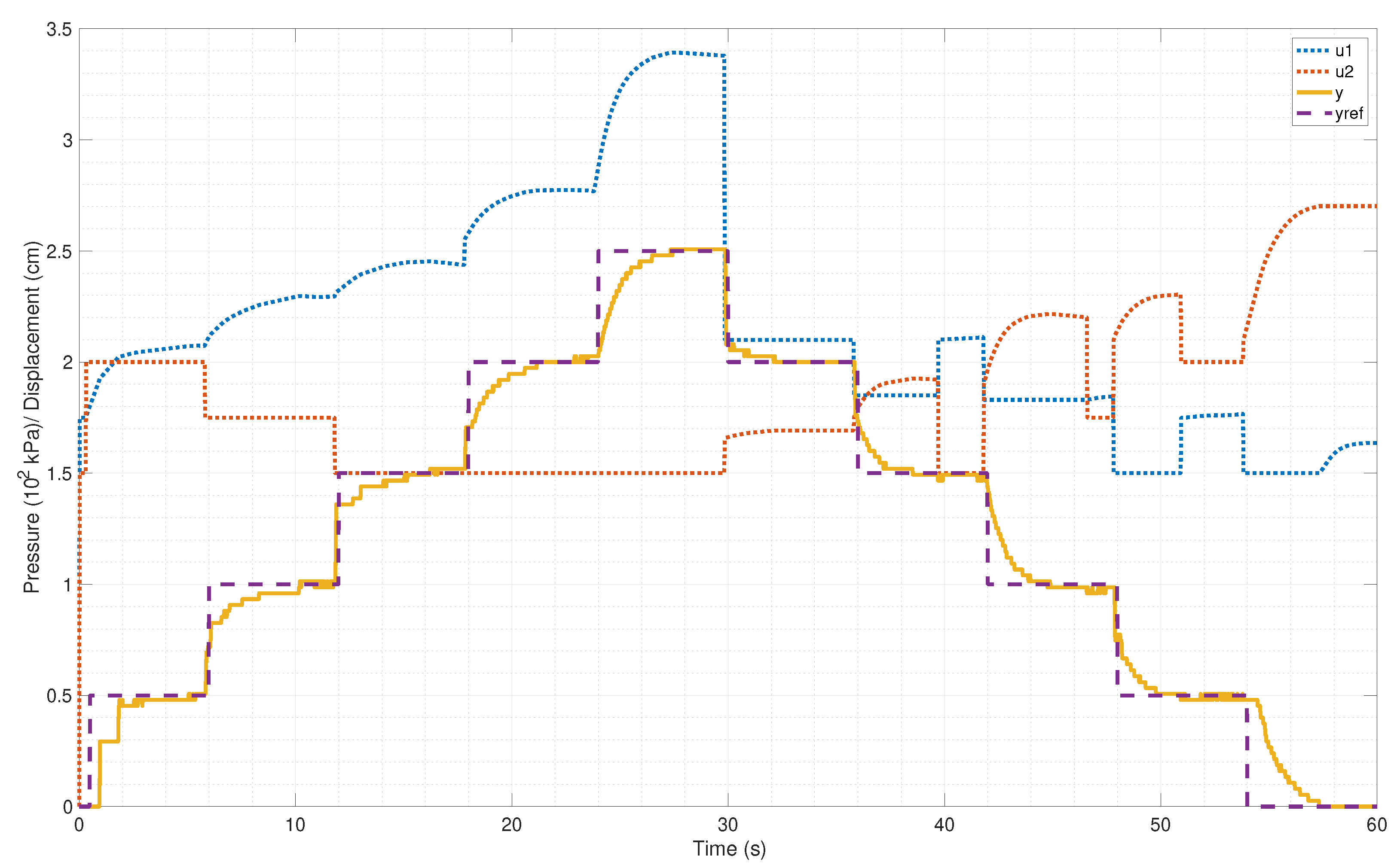
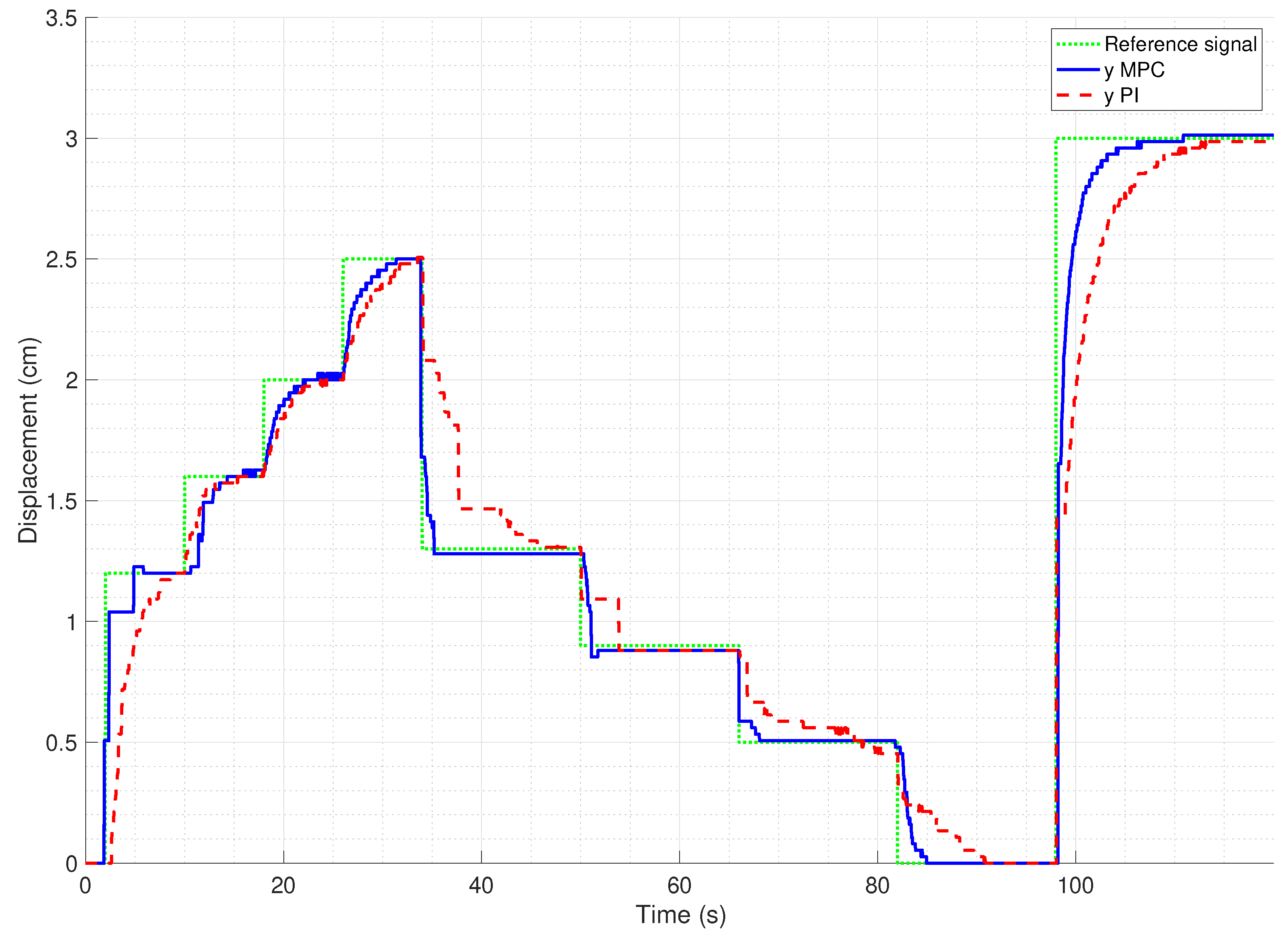
The developed SMPC has been compared to our previously developed Gain-scheduled Proportional–Integral–Derivative (GSPID) controller [45], as shown in Figure 10. Even though both controllers are based on linear models, MPC, in general, has the advantage of more readily able to handle constraints.

3. Results

Figure 11 shows the results of set point experiments to compare the performance of the developed SMPC with the GSPID controller. The SMPC performs well to follow the set point with average rise time, T r , settling time, T s , overshoot, O S , and steady-state error, E s s of 1.49 s, 3.69 s, 0.62%, and 0.51%, respectively, as shown in Table 4. Compared to the GSPID controller, the SMPC has smaller average values for all the parameters. This is because the GSPID controller is based on a single-input single-output (SISO) system that is not able to achieve a fine displacement control. Therefore, it is not able to produce a good set point regulation once overshoot occurs. Therefore, it is tuned to get the best steady-state response, i.e., minimal overshoot and steady-state error at the expense of the transient response, i.e., rise time and settling time.
Figure 12 shows the tracking performance of the SMPC controller to a staircase signal. The output displacement, D o u t (yellow) shows good tracking to reference displacement, D r e f (purple). The average rise time, settling time, overshoot, and steady-state error are 2.16 s, 3.47 s, 1.25%, and 1.25% for increasing staircase tracking and 1.26 s, 2.27 s, 1.13%, and −0.07% for decreasing staircase tracking, as shown in Table 5. To calculate rise time or fall time for each step change, the response is normalized to be in the range of [ 0 , | y s s y r e f , i n i t i a l | ] where y s s is the steady-state response value and y r e f , i n i t i a l is the initial reference value. For example, for a reference change from 1.5 to 2 with steady-state response of 2.01, the range would be [ 0 , 2.01 1.5 = 0.51 ] .
The SMPC tracking performance is also compared with the result from GSPID controller, as shown in Figure 13 and Table 6. The result shows that the SMPC, in general, has lower average values of transient and steady-state responses with average T r , T s , O S , and E s s of 2.96 s, 3.67 s, 1.24%, and 0.74% for forward actuation, and 1.53 s, 2.31 s, 1.27%, and 0.20% for reverse actuation, compared to the GSPID’s values of 4.28 s, 6.06 s, 0.01% and 0.01% for forward actuation, and 7.46 s, 8.63 s, −2.29% and −2.29% for reverse actuation. Even though GSPID performs better than SMPC in O S and E s s for forward actuation, the values of SMPC are still low and acceptable. Taken together, these results suggest that the SMPC has a better tracking performance than the GSPID.

4. Conclusions

In this study, we set out to determine the feasibility of position control using switching MPC for a translational antagonistic-pair TMM servo actuator. It was found that the controller was able to track setpoint and staircase signals in the actual system. Its performance was also compared to our previously developed GSPID controller. It was shown that the SMPC is better than the GSPID controller in both transient and steady-state responses. The results of this study indicate the feasibility of a predictive control for a TMM-actuated pneumatic cylinder, which would facilitate future development of a compliant actuator for safe human–robot interaction. Another focus of this research is to extend the position control range of the servo actuator, which has resulted in the novel method as explained previously. While using a conventional setup requires a larger space to accommodate the increased length as explained in Section 2.1, it is unknown if it can produce a better control. A study to compare the performance of a setup without pulleys and the elaborated configuration to that of this research could thus be useful.

Author Contributions

Conceptualization, M.A.M.Y. and A.A.M.F.; methodology, M.A.M.Y., A.A.M.F., and M.S.H.B.; software, M.A.M.Y.; validation, M.A.M.Y. and M.S.H.B.; formal analysis, M.A.M.Y. and M.S.H.B.; investigation, M.A.M.Y., A.A.M.F. and M.S.H.B.; resources, M.A.M.Y., A.A.M.F. and M.S.H.B.; data curation, M.A.M.Y.; writing—original draft preparation, M.A.M.Y.; writing—review and editing, M.A.M.Y., A.A.M.F. and S.M.; visualization, M.A.M.Y.; supervision, A.A.M.F., M.F.R. and M.I.S.; project administration, A.A.M.F.; funding acquisition, A.A.M.F., S.M. All authors have read and agreed to the published version of the manuscript.

Funding

This research received no external funding.

Institutional Review Board Statement

Not applicable.

Informed Consent Statement

Not applicable.

Data Availability Statement

Not applicable.

Acknowledgments

The authors would like to acknowledge the sponsorship provided by Ministry of Higher Education Malaysia (MOHE) through support under Fundamental Research Grant Scheme (FRGS/1/2019/TK04/UTM/02/41). We also would like to express appreciation to Universiti Teknologi Malaysia (UTM), vote no. (5F137), and Engineering Research Centre, MARDI for facilities support and all the A2Lab UTM members for their direct or indirect support in making this publication possible.

Conflicts of Interest

The authors declare no conflict of interest.

Abbreviations

The following abbreviations are used in this manuscript:
AIArtificial intelligence
GSPIDGain-scheduled Proportional–Integral–Derivative
MMMcKibben muscle
MPCModel Predictive Control
NNNeural network
PAMPneumatic artificial muscle
PIDProportional–Integral–Derivative
PMAPneumatic muscle actuator
PWAPiecewise Affine
SMPCSwitching Model Predictive Control
TMMThin McKibben muscle

References

  1. Mao, Z.; Iizuka, T.; Maeda, S. Bidirectional Electrohydrodynamic Pump with High Symmetrical Performance and Its Application to a Tube Actuator. Sens. Actuat. A Phys. 2021, 332, 113168. [Google Scholar] [CrossRef]
  2. Faudzi, A.A.; Azmi, N.I.; Sayahkarajy, M.; Xuan, W.L.; Suzumori, K. Soft Manipulator Using Thin McKibben Actuator. In Proceedings of the 2018 IEEE/ASME International Conference on Advanced Intelligent Mechatronics (AIM), Auckland, New Zealand, 9–12 July 2018; pp. 334–339. [Google Scholar] [CrossRef]
  3. Peng, Y.; Liu, Y.; Yang, Y.; Liu, N.; Sun, Y.; Liu, Y.; Pu, H.; Xie, S.; Luo, J. Development of Continuum Manipulator Actuated by Thin McKibben Pneumatic Artificial Muscle. Mechatronics 2019, 60, 56–65. [Google Scholar] [CrossRef]
  4. Liu, Y.; Yang, Y.; Peng, Y.; Zhong, S.; Liu, N.; Pu, H. A Light Soft Manipulator With Continuously Controllable Stiffness Actuated by a Thin McKibben Pneumatic Artificial Muscle. IEEE Asme Trans. Mechatronics 2020, 25, 1944–1952. [Google Scholar] [CrossRef]
  5. Mohamed, M.F.; Hanif, A.S.M.; Faudzi, A.A. Segmentation of a Soft Body and Its Bending Performance Using Thin McKibben Muscle. Int. J. Automot. Mech. Eng. 2020, 17, 7533–7541. [Google Scholar] [CrossRef]
  6. Wang, S.; Sato, K. High-Precision Motion Control of a Stage with Pneumatic Artificial Muscles. Precis. Eng. 2016, 43, 448–461. [Google Scholar] [CrossRef]
  7. Shen, X. Nonlinear Model-Based Control of Pneumatic Artificial Muscle Servo Systems. Control Eng. Pract. 2010, 18, 311–317. [Google Scholar] [CrossRef]
  8. Abd. Rahman, R.; Sepehri, N. Design and Experimental Evaluation of a Dynamical Adaptive Backstepping-Sliding Mode Control Scheme for Positioning of an Antagonistically Paired Pneumatic Artificial Muscles Driven Actuating System. Int. J. Control 2017, 90, 265–290. [Google Scholar] [CrossRef]
  9. Dao, Q.T.; Nguyen, M.L.; Yamamoto, S.i. Discrete-Time Fractional Order Integral Sliding Mode Control of an Antagonistic Actuator Driven by Pneumatic Artificial Muscles. Appl. Sci. 2019, 9, 2503. [Google Scholar] [CrossRef]
  10. Ohta, P.; Valle, L.; King, J.; Low, K.; Yi, J.; Atkeson, C.G.; Park, Y.L. Design of a Lightweight Soft Robotic Arm Using Pneumatic Artificial Muscles and Inflatable Sleeves. Soft Robot. 2018, 5, 204–215. [Google Scholar] [CrossRef] [PubMed]
  11. Jiang, F.; Tao, G.; Li, Q. Analysis and Control of a Parallel Lower Limb Based on Pneumatic Artificial Muscles. Adv. Mech. Eng. 2017, 9. [Google Scholar] [CrossRef]
  12. Son, N.N.; Kien, C.V.; Anh, H.P.H. A Novel Adaptive Feed-Forward-PID Controller of a SCARA Parallel Robot Using Pneumatic Artificial Muscle Actuator Based on Neural Network and Modified Differential Evolution Algorithm. Robot. Auton. Syst. 2017, 96, 65–80. [Google Scholar] [CrossRef]
  13. Ugurlu, B.; Forni, P.; Doppmann, C.; Sariyildiz, E.; Morimoto, J. Stable Control of Force, Position, and Stiffness for Robot Joints Powered via Pneumatic Muscles. IEEE Trans. Ind. Inform. 2019, 15, 6270–6279. [Google Scholar] [CrossRef]
  14. Anh, H.P.H. Online Tuning Gain Scheduling MIMO Neural PID Control of the 2-Axes Pneumatic Artificial Muscle (PAM) Robot Arm. Exp. Syst. Appl. 2010, 37, 6547–6560. [Google Scholar] [CrossRef]
  15. Zhong, J.; Zhou, X.; Luo, M. A New Approach to Modeling and Controlling a Pneumatic Muscle Actuator-Driven Setup Using Back Propagation Neural Networks. Complexity 2018, 2018, 4160504. [Google Scholar] [CrossRef]
  16. Anh, H.P.H.; Son, N.N.; Nam, N.T. Adaptive Evolutionary Neural Control of Perturbed Nonlinear Serial PAM Robot. Neurocomputing 2017, 267, 525–544. [Google Scholar] [CrossRef]
  17. Al-Ibadi, A.; Nefti-Meziani, S.; Davis, S.; Theodoridis, T. Novel Design and Position Control Strategy of a Soft Robot Arm. Robotics 2018, 7, 72. [Google Scholar] [CrossRef]
  18. Yager, R.R.; Zadeh, L.A. An Introduction to Fuzzy Logic Applications in Intelligent Systems; Springer: New York, USA, 2012; Volume 165. [Google Scholar]
  19. Leephakpreeda, T. Fuzzy Logic Based PWM Control and Neural Controlled-Variable Estimation of Pneumatic Artificial Muscle Actuators. Exp. Syst. Appl. 2011, 38, 7837–7850. [Google Scholar] [CrossRef]
  20. Anh, H.P.H.; Ahn, K.K. Hybrid Control of a Pneumatic Artificial Muscle (PAM) Robot Arm Using an Inverse NARX Fuzzy Model. Eng. Appl. Artif. Intell. 2011, 24, 697–716. [Google Scholar] [CrossRef]
  21. Chandrapal, M.; Chen, X.; Wang, W.; Hann, C. Nonparametric Control Algorithms for a Pneumatic Artificial Muscle. Exp. Syst. Appl. 2012, 39, 8636–8644. [Google Scholar] [CrossRef]
  22. Feng, Y.; Ide, T.; Nabae, H.; Endo, G.; Sakurai, R.; Ohno, S.; Suzumori, K. Experimental Comparison of Antagonistic Hydraulic Muscle Actuation under Single/Dual and Zero/Overlapped Servovalve Configurations. Mechatronics 2022, 83, 102737. [Google Scholar] [CrossRef]
  23. Mohd Faudzi, A.A.; Ooga, J.; Goto, T.; Takeichi, M.; Suzumori, K. Index Finger of a Human-Like Robotic Hand Using Thin Soft Muscles. IEEE Robot. Autom. Lett. 2018, 3, 92–99. [Google Scholar] [CrossRef]
  24. Mohd Faudzi, A.A.; Endo, G.; Kurumaya, S.; Suzumori, K. Long-Legged Hexapod Giacometti Robot Using Thin Soft McKibben Actuator. IEEE Robot. Autom. Lett. 2018, 3, 100–107. [Google Scholar] [CrossRef]
  25. Woods, B.K.S.; Choi, Y.T.; Kothera, C.S.; Wereley, N.M. Control System Development for Pneumatic Artificial Muscle-Driven Active Rotor Systems. J. Guid. Control Dyn. 2013, 36, 1177–1185. [Google Scholar] [CrossRef]
  26. Al-Fahaam, H.; Nefti-Meziani, S.; Theodoridis, T.; Davis, S. The Design and Mathematical Model of a Novel Variable Stiffness Extensor-Contractor Pneumatic Artificial Muscle. Soft Robot. 2018, 5, 576–591. [Google Scholar] [CrossRef] [PubMed]
  27. Andrikopoulos, G.; Nikolakopoulos, G.; Manesis, S. Pneumatic Artificial Muscles: A Switching Model Predictive Control Approach. Control Eng. Pract. 2013, 21, 1653–1664. [Google Scholar] [CrossRef]
  28. Andrikopoulos, G.; Nikolakopoulos, G.; Manesis, S. Advanced Nonlinear PID-based Antagonistic Control for Pneumatic Muscle Actuators. IEEE Trans. Ind. Electron. 2014, 61, 6926–6937. [Google Scholar] [CrossRef]
  29. Zhao, L.; Liu, X.; Wang, T. Observer-Based Nonlinear Decoupling Control for Two-Joint Manipulator Systems Driven by Pneumatic Artificial Muscles. J. Dyn. Syst. Meas. Control Trans. ASME 2020, 142, 041001. [Google Scholar] [CrossRef]
  30. Schindele, D.; Aschemann, H. Nonlinear Model Predictive Control of a High-Speed Linear Axis Driven by Pneumatic Muscles. In Proceedings of the 2008 American Control Conference, Seattle, WA, USA, 11–13 June 2008; pp. 3017–3022. [Google Scholar]
  31. Andrikopoulos, G.; Nikolakopoulos, G.; Arvanitakis, I.; Manesis, S. Switching Model Predictive Control of a Pneumatic Artificial Muscle. Int. J. Control Autom. Syst. 2013, 11, 1223–1231. [Google Scholar] [CrossRef]
  32. Andrikopoulos, G.; Nikolakopoulos, G.; Arvanitakis, I.; Manesis, S. Piecewise Affine Modeling and Constrained Optimal Control for a Pneumatic Artificial Muscle. IEEE Trans. Ind. Electron. 2014, 61, 904–916. [Google Scholar] [CrossRef]
  33. Andrikopoulos, G.; Nikolakopoulos, G.; Manesis, S. Adaptive Internal Model Control Scheme for a Pneumatic Artificial Muscle. In Proceedings of the 2013 European Control Conference, Zurich, Switzerland, 17–19 July 2013; pp. 772–777. [Google Scholar]
  34. Andrikopoulos, G.; Nikolakopoulos, G.; Manesis, S. Non-Linear Control of Pneumatic Artificial Muscles. In Proceedings of the 2013 21st Mediterranean Conference on Control and Automation, Crete, Greece, 25–28 June 2013; Antsaklis, P., Valavanis, K., Tsourveloudis, N., Zingaretti, P., Moreno, L., Eds.; pp. 729–734. [Google Scholar]
  35. Anh, H.P.H.; Son, N.N.; Kien, C.V. Adaptive Neural Compliant Force-Position Control of Serial PAM Robot. J. Intell. Robot. Syst. 2018, 89, 351–369. [Google Scholar] [CrossRef]
  36. Chan, C.Y.; Chong, S.H.; Loh, S.L.; Alias, A.; Kasdirin, H.A. Positioning Control of an Antagonistic Pneumatic Muscle Actuated System Using Feedforward Compensation with Cascaded Control Scheme. Int. J. Integr. Eng. 2020, 12, 70–74. [Google Scholar] [CrossRef]
  37. Martens, M.; Zawatzki, J.; Seel, T.; Boblan, I. A Pneumatic-Muscle-Actuator-Driven Knee Rehabilitation Device for CAM Therapy. In Proceedings of the 2019 41st Annual International Conference of the Ieee Engineering in Medicine and Biology Society (Embc), Berlin, Germany, 23–27 July 2019; pp. 6237–6242. [Google Scholar]
  38. Tang, T.F.; Chong, S.H. Practical Controller Design for Ultra-Precision Positioning of Stages with a Pneumatic Artificial Muscle Actuator. In Proceedings of the International Technical Postgraduate Conference, Johor, Malaysia, 7 December 2017; IOP Conference Series-Materials Science and Engineering. Harun, S.W., Latiff, A.A., Eds.; Volume 210. [Google Scholar]
  39. Tang, T.F.; Chong, S.H.; Noto, R.M.; Sato, K. Practical Control Strategy for Positioning Control of Pneumatic Artificial Muscles Driven Stage: Improved NCTF Control. IEEE Access 2019, 7, 85513–85524. [Google Scholar] [CrossRef]
  40. Jouppila, V.; Gadsden, S.A.; Ellman, A. Experimental Comparisons of Sliding Mode Controlled Pneumatic Muscle and Cylinder Actuators. J. Dyn. Syst. Meas. Control Trans. ASME 2014, 136, 044503. [Google Scholar] [CrossRef]
  41. Kurumaya, S.; Nabae, H.; Endo, G.; Suzumori, K. Design of Thin McKibben Muscle and Multifilament Structure. Sens. Actuat. A Phys. 2017, 261, 66–74. [Google Scholar] [CrossRef]
  42. Mhd Yusoff, M.; Mohd Faudzi, A.; Hassan Basri, M.; Rahmat, M.F. A Piecewise Affine System Modeling Approach of Thin McKibben Muscle Servo Actuator. In Proceedings of the Enabling Industry 4.0 through Advances in Mechatronics, Pekan, Malaysia, 20 September 2021; Springer Nature Singapore: Pekan, Malaysia, 2021. [Google Scholar] [CrossRef]
  43. Schulte, H.F., Jr. The Characteristics of the McKibben Artificial Muscle (1961) The Application of External Power in Prosthetics and Orthotics; National Academy of Sciences-National Research Council: Washington, DC, USA, 1961; pp. 94–115. [Google Scholar]
  44. Bemporad, A. Hybrid Toolbox—User’s Guide; IMT School for Advanced Studies Lucca: Lucca, Italy, 2004. [Google Scholar]
  45. Mhd Yusoff, M.A.; Mohd Faudzi, A.A.; Hassan Basri, M.S. Feasibility of Pi Control for a Double-Acting Cylinder Actuated by Mckibben Muscles. In Proceedings of the RiTA 2020, Cardiff, UK, 30 October–1 November 2020; Lecture Notes in Mechanical Engineering. Chew, E., Abdul Majeed, P.P., Liu, A., Platts, P., Myung, J., Kim, H., Kim, J.H., Eds.; Springer: Singapore, 2021; pp. 327–339. [Google Scholar] [CrossRef]
  46. Herceg, M.; Kvasnica, M.; Jones, C.N.; Morari, M. Multi-Parametric Toolbox 3.0. In Proceedings of the 2013 European Control Conference (ECC), Zurich, Switzerland, 17–19 July 2013; pp. 502–510. [Google Scholar] [CrossRef]
  47. Lofberg, J. YALMIP: A Toolbox for Modeling and Optimization in MATLAB. In Proceedings of the 2004 IEEE International Conference on Robotics and Automation, New Orleans, LA, USA, 1 May 2004; (IEEE Cat. No.04CH37508). pp. 284–289. [Google Scholar] [CrossRef]
  48. Torrisi, F.; Bemporad, A. HYSDEL—A Tool for Generating Computational Hybrid Models for Analysis and Synthesis Problems. IEEE Trans. Control Syst. Technol. 2004, 12, 235–249. [Google Scholar] [CrossRef]
  49. Rawlings, J.B.; Mayne, D.Q.; Diehl, M.M. Model Predictive Control: Theory, Computation and Design, 2nd ed.; Nob Hill Publishing: Santa Barbara, CA, USA, 2020. [Google Scholar]
  50. Borrelli, F.; Bemporad, A.; Morari, M. Predictive Control for Linear and Hybrid Systems; Cambridge University Press: Cambridge, UK, 2017. [Google Scholar]
  51. Mayne, D.Q.; Rawlings, J.B.; Rao, C.V.; Scokaert, P.O.M. Constrained Model Predictive Control: Stability and Optimality. Automatica 2000, 36, 789–814. [Google Scholar] [CrossRef]
  52. Liberzon, D. Switching in Systems and Control; Birkhauser: Boston, MA, USA, 2003. [Google Scholar]
  53. Özkan, L.; Kothare, M.V. Stability Analysis of a Multi-Model Predictive Control Algorithm with Application to Control of Chemical Reactors. J. Process Control 2006, 16, 81–90. [Google Scholar] [CrossRef]
Figure 1. The prototype’s drawing in computer-aided design. Reprinted by permission from Springer Nature: Springer eBook [42], copyright 2022. (a) Isometric view of the top part; (b) Cross-section view of the bottom part.
Actuators 11 00233 g001
Figure 2. Illustration of antagonistic translational TMM servoactuator setup for 40 mm position control with no modification. The length of the setup has to be more than 36 cm. (a) Rightmost position; (b) center position; (c) leftmost position.
Actuators 11 00233 g002
Figure 3. Comparison between a muscle with slack and a muscle without slack.
Actuators 11 00233 g003
Figure 4. Top muscle pair with slack and passive contraction.
Actuators 11 00233 g004
Figure 5. Comparison of braid angle before and after contraction. Initial braid angle, θ i , is smaller than final braid angle, θ f .
Actuators 11 00233 g005
Figure 6. Dynamic model of the TMM servo actuator. Reprinted by permission from Springer Nature: Springer eBook [42], copyright 2022.
Actuators 11 00233 g006
Figure 7. The prototype fitted with a Gefran potentiometer.
Actuators 11 00233 g007
Figure 8. Overview of the experiment setup. Reprinted by permission from Springer Nature: Springer eBook [45], copyright 2021, with some modification.
Actuators 11 00233 g008
Figure 9. Overall SMPC system.
Actuators 11 00233 g009
Figure 10. Schematic of the Gain-scheduled Proportional-Integral-Derivative (GSPID) controller.
Actuators 11 00233 g010
Figure 11. Result of SMPC versus GSPID setpoint tracking experiments.
Actuators 11 00233 g011
Figure 12. Graph of SMPC staircase tracking.
Actuators 11 00233 g012
Figure 13. Comparison between SMPC and GSPID staircase tracking.
Actuators 11 00233 g013
Table 1. Summary of the contributions of this paper.
ContributionDetailsMain References
ConfigurationTranslational antagonistic-pair thin McKibben muscle (TMM) servo actuator with maximum control of 40 mmShen et al. [7] (conventional McKibben muscle (MM), max. control 15 mm), Tang et al. [39] (conventional MM, max. control 6.5 mm)
ControlSwitching Model Predictive Control (SMPC)Shen et al. [7] (sliding mode control, conventional MM), Andrikopoulos et al. [31,32] (single-acting, conventional MM)
Table 2. Specifications of the TMM used.
Pressure (MPa)Maximum Force a (N)Maximum Contraction Ratio a (%)
0.112.5
0.2515
0.31021
0.41525
0.52028
a Estimated values.
Table 3. Feedforward control lookup table.
Reference Displacement (cm)Forward-Reverse Switch a Feedforward Control (MPa)
r 0.5 10.175
0.5 < r 1.0 10.18
1.0 < r 1.5 10.21
1.5 < r 2.0 10.218
r > 2.0 10.225
r 0.5 00.21
0.5 < r 1.0 00.19
1.0 < r 1.5 00.175
r > 1.5 00.165
a 1: Forward, 0: Reverse.
Table 4. Comparison between SMPC and GSPID setpoint tracking performances.
T r (s) T s (s) OS (%) E ss (%)
Step (cm)MPCPIDMPCPIDMPCPIDMPCPID
0.52.253.104.539.602.001.402.001.40
1.01.513.803.686.401.001.001.001.00
1.50.034.405.458.200.001.33−0.671.33
2.01.714.602.5811.300.001.500.001.50
2.51.105.403.1510.800.400.400.400.40
3.02.326.402.7212.600.330.330.330.33
Average1.494.623.699.820.620.990.510.99
Table 5. SMPC staircase tracking performances.
Actuation x 0 (cm) x f (cm) T r (s) T s (s) OS (%) E ss (%)
Forward0.00.50.904.552.002.00
0.51.02.314.161.001.00
1.01.52.063.041.331.33
1.52.03.143.151.501.50
2.02.52.392.470.400.40
Average 2.163.471.251.25
Reverse2.52.00.720.950.000.00
2.01.51.161.300.670.67
1.51.01.281.981.001.00
1.00.51.293.834.00−2.00
0.50.01.863.310.000.00
Average 1.262.271.13−0.07
Table 6. Comparison between SMPC and GSPID staircase tracking performances.
Actuation x 0 x f T r (s) T s (s) OS (%) E ss (%)
(cm)(cm)MPCPIDMPCPIDMPCPIDMPCPID
Forward0.01.22.853.703.825.602.500.000.000.00
0.03.02.325.902.7212.380.33−0.330.33−0.33
1.21.62.913.104.303.201.880.001.880.00
1.62.03.863.803.993.901.500.001.500.00
2.02.52.864.903.505.200.000.400.000.40
Average 2.964.283.676.061.240.010.740.01
Reverse2.51.31.018.601.1910.101.540.77−1.540.77
1.30.90.753.801.733.905.56−2.22−2.22−2.22
0.90.51.6411.802.0514.30−2.00−10.002.00−10.00
0.50.01.308.802.938.800.000.000.000.00
Average 1.537.462.318.631.27−2.29−0.20−2.29
Publisher’s Note: MDPI stays neutral with regard to jurisdictional claims in published maps and institutional affiliations.

