Article

Research on the Influence of Friction Pairs on the Output Characteristics of the Piezoelectric Ultrasonic Actuator

State Key Laboratory of Robotics and System, Harbin Institute of Technology, Harbin 150001, China
*
Authors to whom correspondence should be addressed.
These authors contributed equally to this work.
Actuators 2022, 11(8), 212; https://doi.org/10.3390/act11080212
Submission received: 18 July 2022 / Revised: 26 July 2022 / Accepted: 28 July 2022 / Published: 30 July 2022

Abstract

:
The piezoelectric ultrasonic actuator is driven by the friction coupling between the stator and mover. Its friction pairs are very important, but there are few studies on the long-term output stability. Therefore, zirconia (ZrO2) is selected as a stator material to form friction pairs with four different wear-resistant materials: silicon nitride (Si3N4), ZrO2, bearing steel (GCr15) and polyether ether ketone (PEEK). Experiments show that the friction pair composed of ZrO2-Si3N4 is the best, and the attenuation percentage of the speed from the initial state to the end state in the speed rising stage of 50 m is 3.66%. A linear piezoelectric platform is developed based on the best friction pair; a maximum speed of 426.2 mm/s and a resolution of 85 nm are achieved.

1. Introduction

The piezoelectric actuator has the advantages of a flexible structure design, no electromagnetic interference, a fast response speed and no reducer [1,2,3,4,5,6]. Therefore, it has attracted more and more attention from researchers and is widely used in aerospace, military, robotics, medical and other fields [7,8,9,10,11]. According to the difference of actuation modes, piezoelectric actuators can be divided into four actuation modes: inertia [12,13], direct drive [14], inchworm [15] and ultrasonic [16,17,18]. With the advantages of a high output speed, a strong load capacity, a simple structure, a flexible design and an unlimited stroke, the piezoelectric actuator has been well used in precision linear motion platforms [19,20,21,22]. The output force of the PUA is transmitted by the friction coupling between the stator and the mover. Therefore, the selection of friction materials has a great impact on the driving effect and the service life of the piezoelectric actuator [23].
In order to reduce the wear between the stator and the mover, a lot of research is carried out. The selection of friction materials not only needs to meet the high friction coefficient but also needs to have excellent wear resistance [24]. Friction pairs usually contain three combinations: organic materials and organic materials, organic materials and inorganic materials and inorganic materials and inorganic materials. In terms of the friction characteristics between organic materials and organic materials, Gu et al. studied the dry sliding friction and wear of polytetrafluoroethylene (PTFE)/Kevlar composites under different vacuums, loads, sliding speeds and temperature performances; the results show that the friction coefficient of the PTFE/Kevlar composite material under vacuum conditions is lower than that of normal temperature conditions, and it has good wear resistance under low and medium vacuum conditions and poor wear resistance under high vacuum conditions. Under vacuum conditions, the friction coefficient and wear rate decrease with the increases in the sliding speed, load and temperature within a certain range [25]. So, the application of the friction pair of organic materials in vacuum is greatly affected by the degree of vacuum, load and temperature.
In terms of the friction characteristics between organic materials and inorganic materials, Liu et al. studied the influence of the PTFE composite and polyimide (PI) composite as mover friction materials on the energy conversion efficiency and mechanical output performance of PUA with phosphorous bronze as the stator friction material. The experimental results show that the PI composite as a friction material can significantly improve the output performance of PUA compared with the PTFE composite. The maximum energy conversion efficiency of the PUA is increased from 24.27% to 41.32% by replacing the PTFE-based friction material with the PI composite material [26]. Song et al. used graphite, molybdenum disulfide or PTFE-filled aramid fiber/PI composite materials as friction materials, which were formed friction pairs with phosphor bronze, respectively, and each friction pair was used to carry out the reciprocating friction and wear systematic research. A comparative study of the friction reduction and wear resistance of polyimide composites shows that graphite exhibits the best lubricity with a lower friction coefficient and wear rate [27]. Qu et al. glued polyphenylene (EKonol) composites to the stator of a traveling-wave PUA, which was combined with rotors of grade 45 steel, copper, stainless steel and aluminum, respectively, and the influence of the drive mode and friction pair combination on the tribological properties of the motor contact interface was analyzed. The experimental results show that, when polyphenylene (EKonol) is combined with a copper rotor, the contact layer can obtain a greater coefficient of friction, a higher output torque and a better wear performance, which can meet the actual operation needs of a traveling ware ultrasonic motor [28]. Therefore, the friction pair composed of suitable organic materials and inorganic materials has a positive effect on improving the energy conversion efficiency, output torque, friction stability and wear resistance of the actuator.
In the research on friction pairs composed of inorganic materials and inorganic materials, Zhang et al. selected ZrO2, alumina (Al2O3), silicon carbide (SiC) and silicon nitride (Si3N4) ceramics as the contact material of the stator, which is matched with the ZrO2, Al2O3, SiC and Si3N4 ceramic of movers, respectively, and the output performance, friction, wear characteristics and performance life of the standing wave linear PUA in the contact interface are studied, respectively. The experimental results show that the combination of SiC-ZrO2, Si3N4-ZrO2 and ZrO2-ZrO2 stator and rotor friction pairs has a better working reliability and durability [29]. Adachi et al. used Al2O3 as a stator and mover materials, respectively, to form friction pairs. The research results show that a smooth wear surface can be formed by two processes of micro-wear and small-wear particles filling surface depression [30]. Olofsson et al. carried out disc and ball tests with Al2O3 as the friction material under different humidity conditions, and the results show that the wear characteristics of the brake disc remained stable between 14,000 and 200,000 RPM under all humidity conditions. For the water lubrication test, the width of the wear track increases significantly between 800 and 200,000 RPM but does not increase significantly in the dryer test. The friction coefficient is the highest under dry conditions and the lowest under water lubrication conditions [31]. Under high temperature and high-pressure conditions, friction sintering of the wear particles is possible when Al2O3 is in friction with itself. Under dry conditions, the friction coefficient is at its maximum when the wear is at its minimum. Therefore, the friction pairs composed of inorganic and inorganic materials and the selection of suitable friction pairs and lubrication conditions have an important impact on the stability and life of the actuator.
Although the research work of friction pairs has been carried out for a long time and a lot of research work has been done, the previous research work mainly aims to evaluate the output characteristics. The research focused on the efficiency and wear characteristics under different environments and different combinations of friction pairs. So, this work uses PUA to study the output speed, output force and long-term running speed stability of different friction pair materials and selects the friction pair with the best output characteristics to develop a linear motion platform, which will provide an idea for improving the long-term running stability of the ultrasonic motor. The main content of the work is as follows. The experimental platform of the friction pair is constructed, and the speed, output force and speed stability of different friction pairs are illustrated in Section 2. The experimental results were discussed, and the material of the friction pair with better characteristics was selected in Section 3. The linear motion platform was developed, and platform characteristics were tested in Section 4.

2. Experimental Platform Construction and Friction Pair Performance Test

The basic configuration and principle of the actuator is introduced first, and then the friction pair testing system built by the actuator is presented. ZrO2 is used as the stator material in the experiment, which constitutes the friction pairs with silicon nitride (Si3N4), ZrO2, bearing steel (GCr15) and polyether ether ketone (PEEK), respectively. The speed, output force and motion stability of different friction pairs were tested, respectively.

2.1. Configuration of the Actuator and Actuating Principle

A. Actuator configuration
Considering the working stability and output characteristics of PUA, the sandwich PUA with four zones of the d33 working mode was selected as the basic configuration in this work. As shown in Figure 1a, the actuator is composed of a luffing lever made of 2A12, six pieces of the four-zone ceramic, six pieces of the electrode plate, a pedestal and a connecting bolt. Two sets of sinusoidal signals with a phase difference of 90°/270° were selected to apply to the ceramic in the horizontal and vertical directions, respectively. Under this driving condition, the motion trajectory of the driving foot is a positive ellipse when it is actuated. The motion trajectory under the excitation signal is shown in Figure 1b, which can ensure that the motion trajectory of the point on the actuator driving foot is a positive ellipse. The main structural parameters of the piezoelectric ultrasonic actuator are shown in Figure 1c. Its overall dimensions in the X, Y and Z directions are 30 mm, 30 mm and 34.2 mm, respectively, and its mass is 0.074 kg.
B. Actuating principle
The motion process of the PUA in a sinusoidal AC excitation signal cycle and the working process of the PUA in one cycle (T) is illustrated by the motion states of the PUA at four special time points: T/4, T/2, 3T/4 and T.
(1)
t = T/4: The excitation voltage applied to the two vertical zones of the piezoelectric ceramics reaches the maximum positive value, and the bending displacement of the PUA along the negative direction of the Y axis reaches the maximum to press down the actuator.
(2)
t = T/2: The excitation voltage applied to the horizontal two regions of the piezoelectric ceramic reaches the maximum value, and the bending displacement of the PUA reaches the maximum along the positive direction of the X-axis. The driving foot moves along the positive X-axis of the actuator between t = T/4 and t = T/2.
(3)
t = 3T/4: The excitation voltage applied to the two vertical zones of the piezoelectric ceramics reaches the maximum negative value, the bending displacement of the PUA along the positive direction of the Y axis reaches the maximum and the driving foot leaves the actuator. The driving foot does not contact the mover between t = T/2 and t = 3T/4.
(4)
t = T: The excitation voltage applied to the left and right zones of the piezoelectric ceramics reaches the maximum negative value, and the bending displacement of the PUA along the negative direction of the X axis reaches the maximum. The driving foot does not contact the mover between t = 3T/4 and t = T.
This is the working process of the PUA in an excitation signal cycle. The PUA pushes the mover in the positive direction of the X-axis during each excitation signal cycle. The mover can realize the movement of a large stroke by the continuous accumulation of multiple cycles. The reverse driving process of the mover can be realized when the phase difference of two sinusoidal AC excitation signals is changed to 270°.

2.2. Friction Pair Performance Test

A. Configuration friction pair performance test
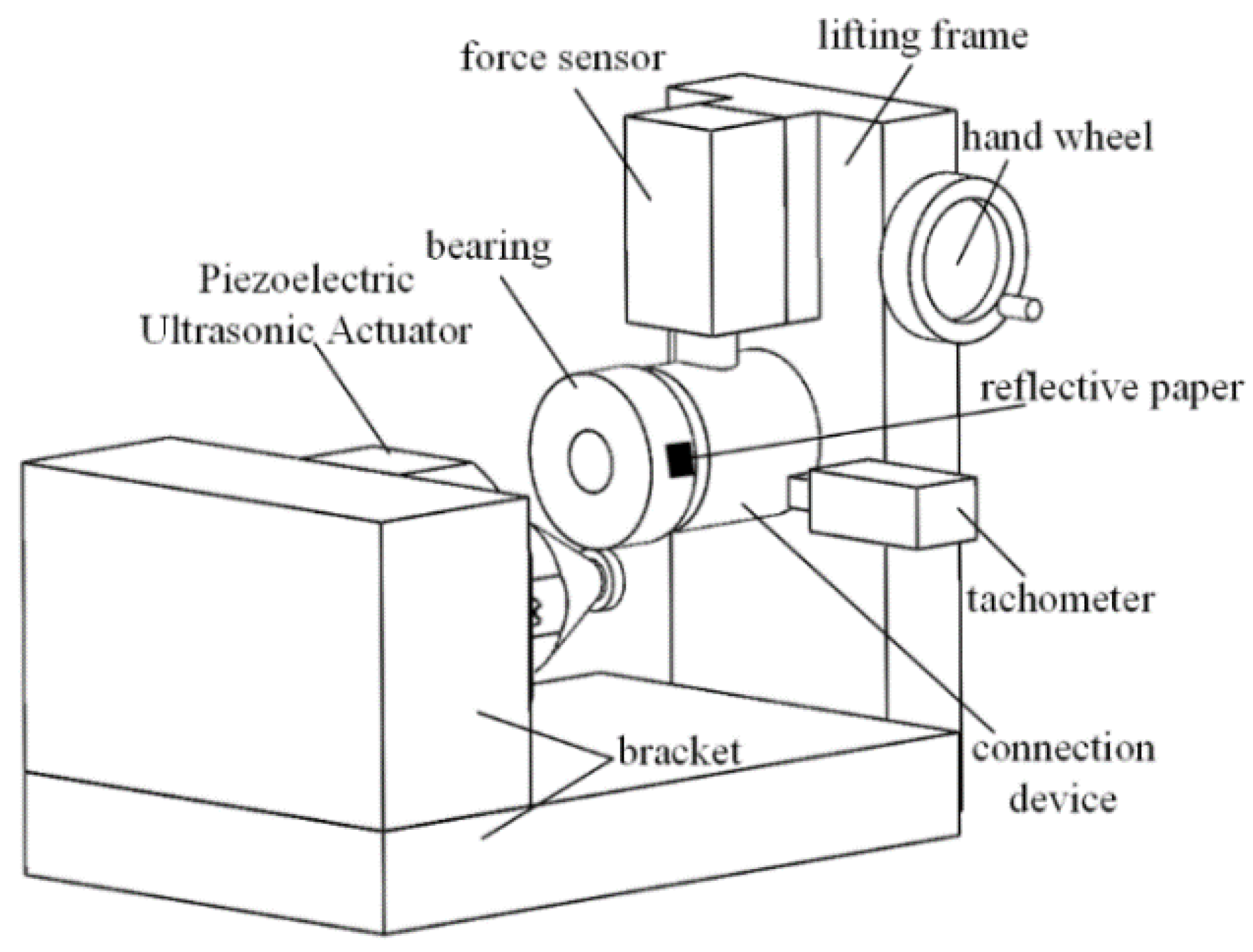
The experimental device shown in Figure 2 was used to test the mechanical output performance and long-term operation output speed stability of the PUA. Because the main wear mechanism of ceramic materials is mechanical fracture, ZrO2 materials have a higher fracture toughness and less wear [20]. In the experiment, ZrO2 was used as the stator material to form friction pairs with four different wear-resistant materials: Si3N4, ZrO2, GCr15 and PEEK. The material parameters are shown in Table 1. The experimental device took the bearing as the mover, the PUA drives the bearing to move, the lifting frame is connected with the force sensor, the force sensor is connected with the mover through the connecting device, the height of the lifting frame is controlled by the hand wheel, the accurate preload value between the stator and the mover can be obtained through the force sensor and the mover is pasted with reflective paper. The laser emitted by the tachometer returns to the tachometer after being reflected by the reflective paper. The speed value of the mover can be obtained by calculating the time interval of the reflected laser.
B. Experiment development and data processing
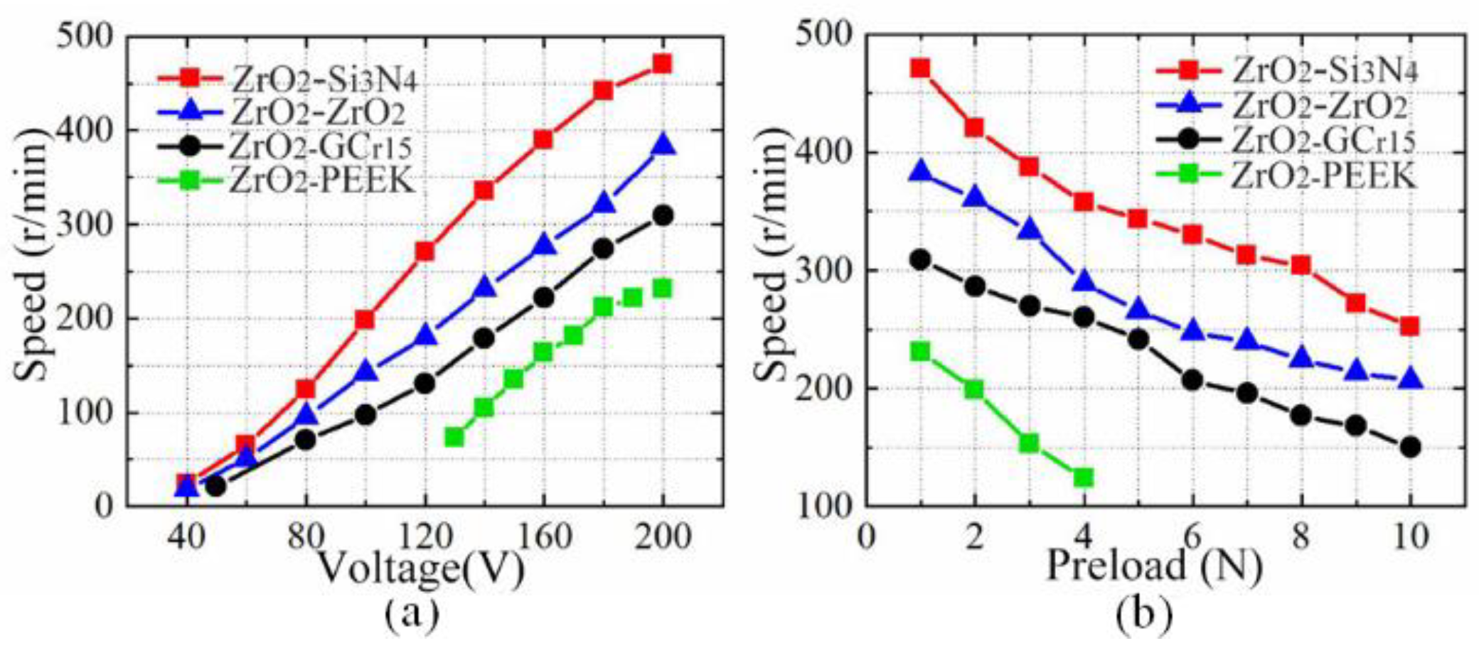
The initial preload value was set to 1 N, the commercial ultrasonic power supply (Model: QD-8D, Harbin Jiangjun precision testing technology Co., Ltd., Harbin, China) was used to provide the excitation signal, the excitation voltage was increased from 40 Vp-p to 200 Vp-p and the relationship between the output speed of the actuator and the excitation voltage is shown in Figure 3a. The experimental results show that the output speed of the PUA increases approximately linearly with the increase in excitation voltage. The output speeds of the friction pair materials from high to low are ZrO2-Si3N4, ZrO2-ZrO2, ZrO2-GCr15 and ZrO2-PEEK. When the excitation voltage is 200 Vp-p, the maximum output speed of the ZrO2-Si3N4 friction pair can reach 470.66 r/min. By contrast, the minimum output speed of the ZrO2-PEEK friction pair is 230.95 r/min. The output speed of the ZrO2-Si3N4 friction pair is about 2.04 times that of the ZrO2-PEEK friction pair, and the ZrO2-PEEK friction pair cannot work when the excitation voltage is less than 130 Vp-p.
The excitation voltage was 200 Vp-p, and the preload between the stator and the mover was increased from 1 N to 10 N. The relationship between the output speed of the actuator and the preload is shown in Figure 3b. The experimental results show that the output speed of the PUA decreases approximately linearly with the increase in the preload. The output speeds of the friction pair materials from high to low are ZrO2-Si3N4, ZrO2-ZrO2, ZrO2-GCr15 and ZrO2-PEEK. When the friction pair material is ZrO2-PEEK, the PUA cannot work when the preload is greater than 4 N.
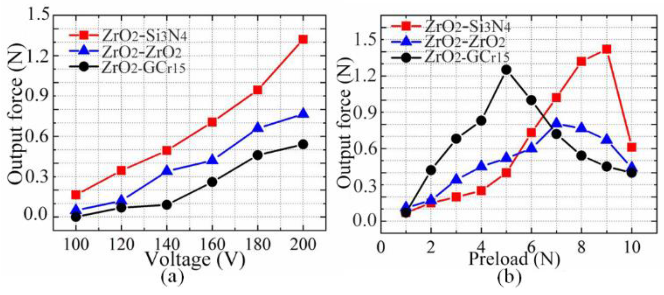
The preload is 8 N, the value of the excitation voltage increases from 100 Vp-p to 200 Vp-p and the relationship between the actuator output force and excitation voltage is shown in Figure 4a. The experimental results show that the output force of the PUA increases approximately linearly with the increase in the excitation voltage. The friction pair materials with the overall output force from high to low are ZrO2-Si3N4, ZrO2-ZrO2 and ZrO2-GCr15. When the excitation voltage is 200 Vp-p, the maximum output force of the ZrO2-Si3N4 friction pair can reach 1.32 N. Under the same conditions, the minimum output force of the ZrO2-GCr15 friction pair is 0.54 N, and the output force of the ZrO2-Si3N4 friction pair is about 2.44 times that.
The value of the excitation voltage is 200 Vp-p, and the preload increases from 1 N to 10 N. The relationship between the actuator output force and the preload is shown in Figure 4b. The experimental results show that the output force of the PUA first increases and then decreases with the increase in the preload. At a lower preload, the output forces of the friction pair materials from high to low are ZrO2-GCr15, ZrO2-ZrO2 and ZrO2-Si3N4. At a high preload, the high output forces of the friction pair materials from high to low are ZrO2-Si3N4, ZrO2-ZrO2 and ZrO2-GCr15, respectively. When the preload is 5 N, 7 N and 9 N, the output forces of the ZrO2-GCr15, ZrO2-ZrO2 and ZrO2-Si3N4 friction pairs reach the maximum, which are 1.25 N, 0.805 N and 1.42 N, respectively. When the preload force is greater than 6.5 N, the output force of ZrO2-Si3N4 is always greater than that of the other friction pairs. Therefore, the output force characteristics of the ZrO2-Si3N4 friction pair combination are better.
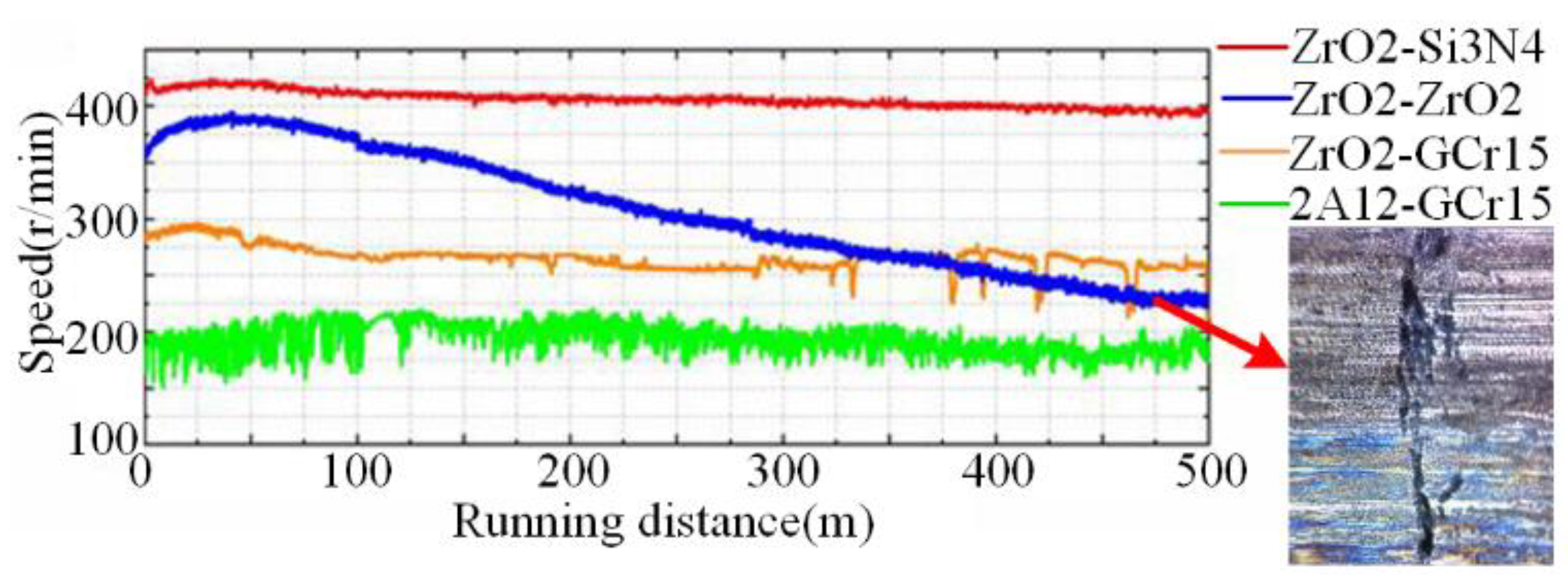
The stability of the output speed of the PUA under different material combinations of friction pairs is the key factor to evaluate each friction pair. Under the experimental conditions that the peak value of the excitation voltage was 200 Vp-p and the preload was 2 N, the PUA drove the bearing to run continuously for 500 m, and the variation law of its output speed with the operating distance was measured, as shown in Figure 5. Firstly, the change in the output speed of the PUA running for a long distance was analyzed. It can be seen from the experimental results that, under the four different friction pair material combinations, the output speed of the PUA experienced a process of rising at the beginning and then fell. The specific output speed changes of the four friction pairs are shown in Table 2.
The running distances of the four kinds of friction pairs of ZrO2-Si3N4, ZrO2-ZrO2, ZrO2-GCr15 and 2A12-GCr15 in the rising stage are 50 m, 40 m, 25 m and 130 m, respectively; the initial speeds are 410 mm/s, 355 mm/s, 285 mm/s and 198 mm/s, respectively. The rising peak speeds are 420 mm/s, 390 mm/s, 295 mm/s and 218 mm/s, respectively. The end speeds are 395 mm/s, 228 mm/s, 258 mm/s and 190 mm/s, respectively. Through calculation, the attenuation percentages of the output speed of the four friction pairs from the initial state to the end state are 3.66%, 35.77%, 9.47% and 4.04%, respectively. The speed attenuation degree of the ZrO2-Si3N4 friction pair is the lowest, which is followed by ZrO2-GCr15 and 2A12-GCr15. ZrO2-ZrO2 is the same kind of friction material, the wear of which is the most severe, and the output speed of the PUA attenuation is the fastest.
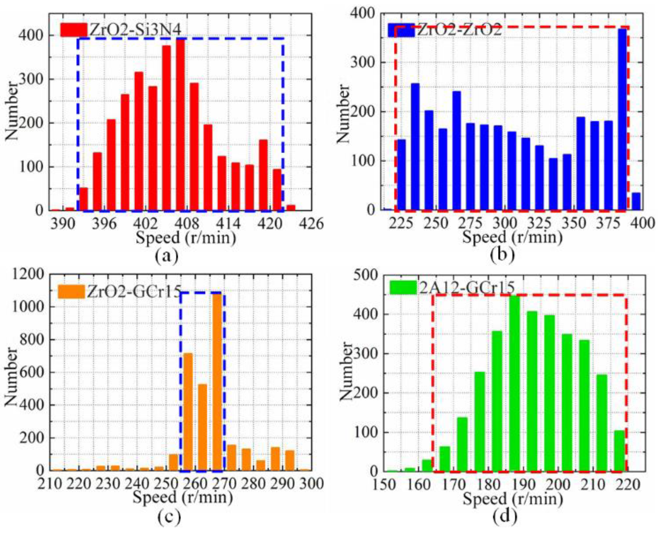
The discreteness of the output velocity of the PUA for long-distance operation was analyzed. It can be seen from Figure 6 that the velocity dispersions of the ZrO2-Si3N4 and ZrO2-GCr15 friction pairs are small, and the velocity dispersion of 2A12-GCr15 is the largest. However, the output speed of the ZrO2-GCr15 combination fluctuates violently in the second half of the whole operation cycle of the PUA, which is caused by cracks on the surface of the abrasive particles and mover. The discrete type of the output speed of the PUA is accurately analyzed by a statistical method. A histogram of the output velocity distribution of the four different friction pairs is shown in Figure 6. It can be seen intuitively that the output speed distributions of ZrO2-Si3N4, ZrO2-GCr15 and 2A12-GCr15 are approximately normal, the output speed distribution of ZrO2-ZrO2 is not obvious and the speed stability is not good.
In order to further quantitatively evaluate the stability of the output speeds of the four friction pairs, the part of the concentrated distribution of the output speeds in the dotted box in Figure 6 was selected for speed distribution analysis, and the mean value (Vm), standard deviation (SD), corrected sum of squares (CSS), coefficient of variation (CV), skewness (S) and kurtosis (K) of their output speeds were calculated, respectively. The calculation formula is as follows:
{ C V = S D x ¯ V m = x 1 + x 2 + x n n S D = ( x 1 x ¯ ) 2 + ( x 2 x ¯ ) 2 + ( x n x ¯ ) 2 n C S S = ( x 1 x ¯ ) 2 + ( x 2 x ¯ ) 2 + ( x n x ¯ ) 2 S = n ( n 1 ) n 2 [ 1 n i = 1 n ( x i x ¯ ) 3 ( 1 n i = 1 n ( x i x ¯ ) 2 ) 3 2 ] K = ( n + 1 ) n ( n 1 ) ( n 2 ) ( n 3 ) i = 1 n ( ( x i x ¯ ) 4 s ) 3 ( n 1 ) 2 ( n 2 ) ( n 3 )
where xi is the speed sample, n is the number of samples and x ¯ is the speed average.
The calculation results are shown in Table 3.
The mean velocity (Vm) reflects the output performance of different friction pairs. The mean velocities (Vm) of ZrO2-Si3N4, ZrO2-ZrO2, ZrO2-GCr15 and 2A12-GCr15 are 406.06 r/min, 307.39 r/min, 265.50 r/min and 193.46 r/min respectively. The output performance of ZrO2-Si3N4 is the best, followed by those of ZrO2-ZrO2 and ZrO2-GCr15, and that of 2A12-GCr15 is the worst. The standard deviation (SD), corrected sum of squares (CSS) and coefficient of variation (CV) reflect the dispersion of speed. The order of the three evaluation indexes from small to large is ZrO2-Si3N4, ZrO2-GCr15 and 2A12-GCr15, ZrO2-ZrO2, which fully shows that the discrete type of the ZrO2-Si3N4 output speed is the smallest, that of ZrO2-GCr15, 2A12-GCr15 is the second smallest and the ZrO2-ZrO2 output speed is the largest. Skewness (S) and kurtosis (K) reflect the distribution of the output speed of the PUA, and skewness (S) reflects the symmetry of the operating speed. The skewness (S) values of ZrO2-Si3N4 and ZrO2-ZrO2 are positive, indicating that their speed is concentrated on the left side of the mean value, and the skewness (S) values of ZrO2-GCr15 and 2A12-GCr15 are negative; it shows that the velocity is concentrated on the right side of the mean value. Kurtosis (K) reflects the aggregation degree of the velocity in the mean center. The kurtosis (K) value of ZrO2-GCr15 is the largest, and the velocity aggregation degree is the best. However, in the second half of the operation, the output velocity fluctuates violently due to the generation of abrasive particles and mover surface cracks.

3. Discussion and Friction Material Selection

According to Hertz contact theory [32], when the stator of the PUA is in contact with the mover, the depth h of the driving foot pressing into the mover can be calculated as follows:
h = F π l × 1 v 2 E ( 2 ln 2 R F π l × R E 1 )
1 E = ( 1 v 1 2 E 1 + 1 v 2 2 E 2 )
where F is the preload between the driving foot and the mover, l is the contact thickness between the driving foot and the mover (mm), R is the radius of the driving foot (mm), h is the driving foot pressuring depth into the mover, v is the equivalent Poisson’s ratio of the stator, E is the equivalent modulus of the friction pair composed of the actuator and the stator, E1 is the elastic modulus of the stator and E2 is the elastic modulus of the mover.
The output force of the PUA was tested by combining different friction pair materials, and the variation law of the output force with the excitation voltage and preload was measured, respectively, the equivalent elastic modulus E and friction coefficient of the four friction pair materials are shown in Table 4.
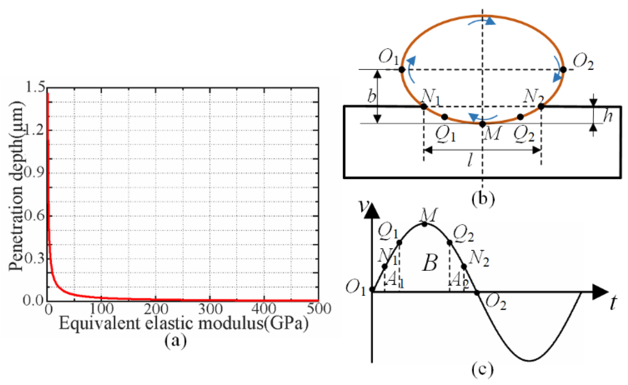
Assuming F = 100 N, l = 2 mm, R = 4 mm and v = 0.3, the relationship between the depth h of the driving foot pressing into the mover and the equivalent elastic modulus E of the stator and mover is obtained, as shown in Figure 7a. It can be seen that the depth h of the driving foot pressing into the mover gradually decreases with the increase in the equivalent elastic modulus E, and the depth h of the driving foot pressing into the mover decreases rapidly when the equivalent elastic modulus E is small. When the equivalent elastic modulus E is large, the depth h of the driving foot into the mover decreases slowly.
The power transmission process between the stator and the mover of the PUA is analyzed. As shown in Figure 7b,c, during the elliptical motion of the point on the driving foot of the PUA, its horizontal velocity can be expressed as follows:
v x = d x = A ω sin ( ω t )
where dx represents the displacement in the horizontal direction, A is the velocity amplitude, ω is the frequency of the speed and its velocity is a sinusoidal curve. When the driving foot is at point O1 in the initial state, the horizontal speed is 0, and when it moves to point M, the horizontal speed reaches the maximum. Then, in the process of driving the foot from point M to point O2, the speed gradually decreases to 0. The stator experiences the process from contact to separation with the mover. Point N1 is the contact point, point N2 is the separation point and points Q1 and Q2 are the points where the horizontal speed of the stator is equal to the speed of the mover, which is called the isokinetic point. When the stator moves from point N1 to point Q1, the stator speed is less than the mover speed, and the friction does negative work to the mover. When the stator moves from point Q1 to point Q2, the speed of the stator is greater than that of the mover, and the friction does positive work to the mover. When the stator moves from point Q2 to point N2, the stator speed is less than the mover speed, and the friction does negative work to the mover. When the positive work and negative work done by the friction on the mover are equal, the output speed of the mover is stable.
For different friction materials, the pressuring depth h between the stator and actuator is closely related to its elastic modulus. The pressuring depth h between the stator and actuator is smaller when the equivalent elastic modulus E is larger, so the position of the contact point between the stator and actuator moves backward. In this case, if the location of the uniform point remains at the previous position, the positive work done by the friction force on the mover remains unchanged, while the negative work decreases, which does not meet the law of energy conservation. Therefore, the isokinetic point must be increased to reduce the positive work and increase the negative work to achieve an energy balance. Therefore, the friction pair combination with the larger equivalent elastic modulus E has a higher output speed.
When the equivalent elastic modulus E of the friction pair material is smaller, the pressuring depth h between the stator and the mover is larger, which leads to a larger effective contact area between the stator and the mover, and the friction force is increased to a certain extent, thus increasing the output force of the PUA. However, when the pressuring depth is too large and exceeds a certain critical value, the elliptical motion trajectory of the stator will “fall” into the mover, which reduces the power transmission efficiency and the output force of the PUA. By comprehensively comparing the mechanical output performance and the stability of the output speed of the PUA under different friction pair material combinations, it can be found that the ZrO2-Si3N4 material combination has a better performance in terms of output speed and speed stability than that of other friction pair materials. The output force of the ZrO2-Si3N4 combination is better under a high preload, but the performance under a low preload is not as good as that of other friction pair combinations. The piezoelectric ultrasonic actuated linear platform is developed in this work, which is rarely used in applications where the output force is required, so the combination of the ZrO2-Si3N4 friction pair is selected. The piezoelectric linear driving platform developed in this work has a low demand for the output force in application, so the ZRO2-Si3N4 friction pair combination is selected.

4. Results

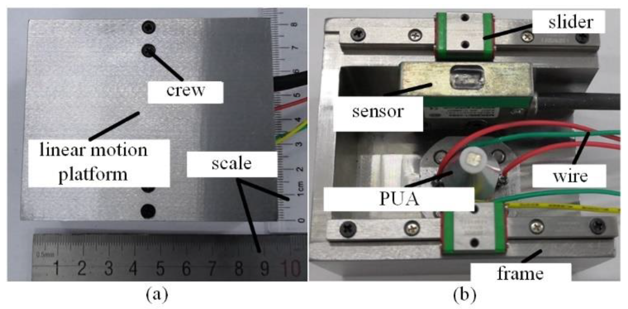
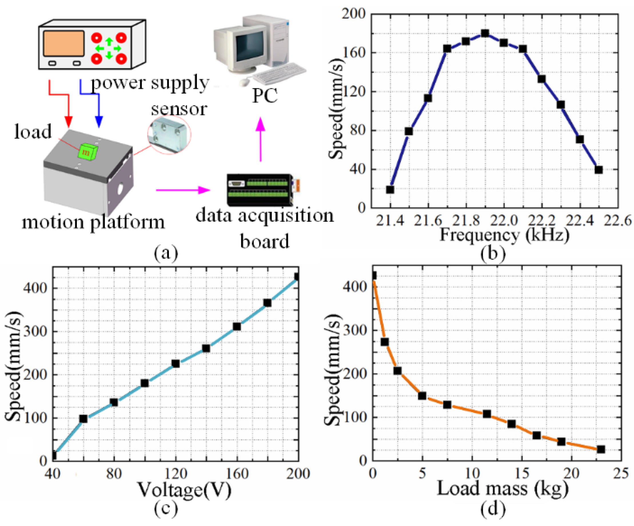
In order to measure the mechanical output characteristics of the PUA linear motion platform, an experimental test system was built. The overall dimensions of the platform in the X, Y and Z directions are 80 mm, 51.5 mm and 66 mm, respectively, as shown in Figure 8 and Figure 9a. The driving power supply of the system adopted the commercial QD-8D ultrasonic power supply. The magnetic grid displacement sensor (Model: MSK 200/1-0085, SIKO GmbH, Buchenbach, Germany) and the data acquisition card (DAQ card) (Model: PCI 2394, Beijing Art Technology Development Co., Ltd., Beijing, China) were used to measure the motion displacement of the linear platform and collect the test data, respectively. The collected data were displayed and processed on the PC; the weight block was placed on the platform to measure the load speed output characteristics of the linear platform.
The speed and frequency characteristics of the linear motion platform were tested to determine the best working frequency point of the linear motion platform by the experimental platform. During the experiment, the excitation voltage was 100 Vp-p, the phase difference of the two excitation signals was 90°, the preload between the driving foot and the mover was 18 N and the frequency of the excitation signal increases from 21.4 kHz to 22.5 kHz. As shown in Figure 9b, the experimental results show that, with the increase in the excitation frequency, the motion speed of the linear platform increases at the beginning and then decreases. When the excitation frequency is 21.9 kHz, the maximum output speed of the linear platform is 179.8 mm/s, indicating that 21.9 kHz is the best working frequency point of the linear motion platform.
The speed and excitation voltage characteristics of the linear platform were tested with the measured optimal frequency point. The experimental results are shown in Figure 9c. It can be seen from the experimental results that the output speed of the linear platform increases significantly with the increase in the excitation voltage, which is approximately linear with the excitation voltage. When the excitation voltage reaches 200 Vp-p, the output speed can reach 426.2 mm/s. When the excitation voltage is less than 40 Vp-p, the output speed is 0, which shows that, when the excitation voltage is less than 40 Vp-p, the foot end displacement of the PUA is not enough to overcome the maximum static friction between the actuator and the mover.
The speed and load characteristics of the platform were tested under an excitation voltage of 200 Vp-p, a frequency of 21.9 kHz and a phase difference of 90°. The experimental results are shown in Figure 9d. The experimental results show that the output speed decreases with the increase in the load mass. When the load mass is less than 5 kg, the output speed decreases faster, and when the load mass is greater than 5 kg, the output speed decreases slowly. When the load mass is 23 kg, the output speed of the platform is 25.75 mm/s, which performs a strong load capacity.
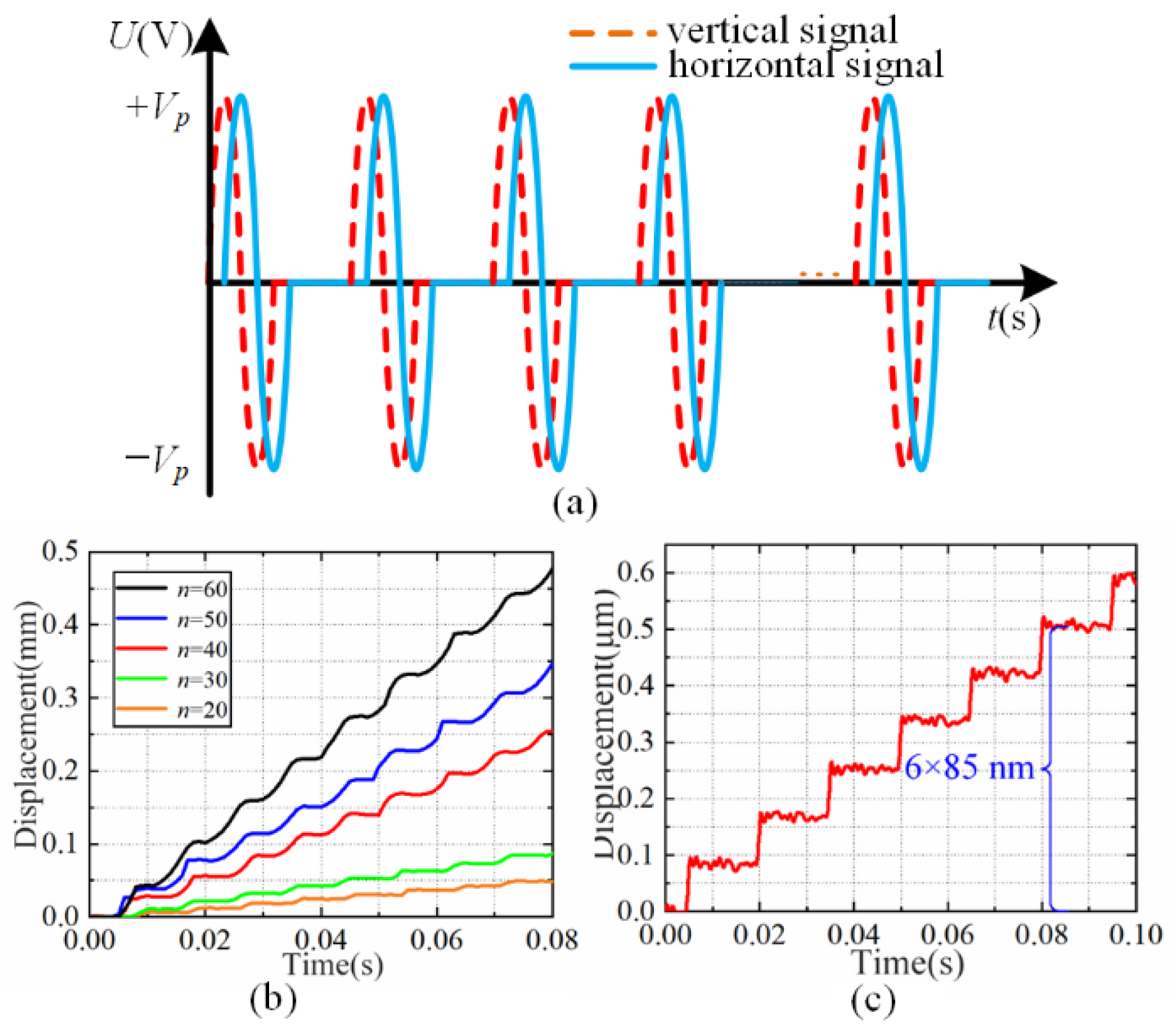
The output displacement resolution of the linear platform was tested under the excitation of the pulsed AC sinusoidal excitation signal, as shown in Figure 10a. The excitation voltage was 100 Vp-p, the excitation signal frequency fr was 21.9 kHz, the frequency fs of the step cycle was 100 Hz and the preload between the driving foot and the mover was 18 N. The output displacement of the linear platform was obtained by changing the number of sinusoidal signals in a step cycle to 20, 30, 40, 50 and 60, respectively, as shown in Figure 10b. The experimental results show that, under the excitation of the pulsed AC sinusoidal excitation signal, the linear platform outputs a stepping motion, and the number n of sinusoidal signals in a step cycle significantly affects the stepping displacement of the linear platform. The measurement resolution of the magnetic grid displacement sensor is 0.5 μm. When the number of signals is less than 5, the magnetic grid displacement sensor can no longer meet the measurement requirements; it was replaced by capacitive displacement sensors (PI D-E20.050, German PI Co., Ltd., Karlsruhe, Germany) with a range of 50 μm and a dynamic resolution of 1nm. The experimental results show that, when there is only one sinusoidal signal, the linear platform can reach a motion step of about 85 nm, that is, the PUA can achieve a nano-level high resolution in the resonant working state when there is only one sinusoidal signal. The output displacement of the linear platform is shown in Figure 10c.
The comparisons between the proposed ultrasonic motor and some existing ultrasonic motors are listed in detail in Table 5. Izuhara et al. proposed a miniature linear ultrasonic motor with a size of 2.6 × 2.6 × 2.2 mm3 and a maximum output speed of 140 mm/s at 150 Vp-p. The motor has a compact structure but a small load capacity [33]. Smithmaitrie et al. proposed a dual transducer ultrasonic motor with a motor size of 85 × 6 × 1 mm3 and a maximum output speed of 176.2 mm/s under 60 Vp-p. The structure of the dual transducer is complex, and the machining accuracy is complex, so it is difficult to ensure the consistency of the actuator [34]. Shi et al. proposed a precision linear ultrasonic motor with a size of 55 × 26 × 14 mm3, and the speed reaches 159 mm/s under a 400 Vp-p driving voltage [35]. The maximum speed of the motor proposed in this paper is 179.8 mm/s under 100 Vp-p, the load mass can reach 23 kg and the resolution in the resonance mode is 85 nm. These performances are significantly better than that of the several motors listed in Table 5. Therefore, the proposed motor has a wide application potential in the fields of high-speed, large-load and precision drive applications.

5. Conclusions

In this study, ZrO2 was used as the driving foot surface material of the PUA to form a friction pair with Si3N4, ZrO2, GCr15 and PEEK, respectively. The variation rules of the output speed with the excitation voltage and preload were tested, respectively, by four friction pairs. The output speeds of the friction pair composed of ZrO2-Si3N4 is the best under the same excitation voltage or preload. Then, the variation rules of the output force with the excitation voltage and preload were tested, respectively. The output force of ZrO2-Si3N4 is always the largest under the same excitation voltage. When the preload force is greater than 6.5 N, the output force of ZrO2-Si3N4 is always greater than that of other friction pairs. Under an excitation signal of 200 Vp-p and a preload of 2 N, different combinations of friction pairs are used to drive the mover for 500 m to test the output stability. In the long-term test of the friction pair composed of ZrO2-Si3N4, the attenuation percentage of the speed from the initial state to the end state in the speed rising stage of 50 m is 3.66%. According to the experimental results, the combination of ZrO2-Si3N4 has the best output characteristics and was thus selected and applied to the linear motion platform. The maximum output speed of the platform can reach 426.2 mm/s; it can achieve a high resolution of about 85 nm and has good load characteristics, which are important to push the technological development of high-end manufacturing equipment. This work also provides an idea for improving the output capacity and long-term operation stability of ultrasonic motors and provides a possibility for expanding the application range of ultrasonic motors.

Author Contributions

Conceptualization, designing, writing—original draft preparation: J.D. and J.C.; experimentation, simulation, analysis: Y.G.; writing—review and editing, supervision: H.L., F.L. and W.C. All authors have read and agreed to the published version of the manuscript.

Funding

This research is funded by the National Natural Science Foundation of China, the China Postdoctoral Science Foundation and the Postdoctoral Science Foundation of Heilongjiang Province; the grant numbers are 5210051275, 2021M690830 and LBH-Z21018, respectively.

Institutional Review Board Statement

Not applicable.

Informed Consent Statement

Not applicable.

Data Availability Statement

Not applicable.

Conflicts of Interest

The authors declare no conflict of interest.

References

  1. Shi, Y.L.; Lou, C.S.; Zhang, J. Investigation on a linear piezoelectric actuator based on stick-slip/scan excitation. Actuators 2021, 10, 39. [Google Scholar] [CrossRef]
  2. Tang, J.Z.; Wei, J.S.; Wang, Y.M.; Xu, Z.; Huang, H. A novel rotation-structure based stick-slip piezoelectric actuator with high consistency in forward and reverse motions. Actuators 2021, 10, 189. [Google Scholar] [CrossRef]
  3. Yu, H.P.; Liu, Y.X.; Tian, X.Q.; Zhang, S.J.; Liu, J.K. A precise rotary positioner driven by piezoelectric bimorphs: Design, analysis and experimental evaluation. Sens. Actuators A Phys. 2020, 313, 112197. [Google Scholar] [CrossRef]
  4. Wang, F.J.; Shi, B.C.; Tian, Y.L.; Huo, Z.C.; Zhao, X.Y.; Zhang, D.W. Design of a novel dual-axis micromanipulator with an asymmetric compliant structure. IEEE/ASME Trans. Mechatron. 2013, 24, 656–665. [Google Scholar] [CrossRef]
  5. Deng, J.; Liu, Y.X.; Li, J.; Zhang, S.J.; Li, K. Displacement linearity improving method of stepping piezoelectric platform based on leg wagging mechanism. IEEE Trans. Ind. Electron. 2022, 69, 6429–6432. [Google Scholar] [CrossRef]
  6. Deng, J.; Liu, S.H.; Liu, Y.X.; Wang, L.; Gao, X.; Li, K. A 2-DOF needle insertion device using inertial piezoelectric actuator. IEEE Trans. Ind. Electron. 2022, 69, 3918–3927. [Google Scholar] [CrossRef]
  7. Gao, X.; Deng, J.; Zhang, S.J.; Li, J.; Liu, Y.X. A compact 2-DOF micro/nano manipulator using single miniature piezoelectric tube actuator. IEEE Trans. Ind. Electron. 2022, 69, 3928–3937. [Google Scholar] [CrossRef]
  8. Ghenna, S.; Giraud, F.; Giraud-Audine, C.; Amberg, M. Vector control of piezoelectric transducers and ultrasonic actuators. IEEE Trans. Ind. Electron. 2018, 65, 4880–4888. [Google Scholar] [CrossRef]
  9. Liu, Y.X.; Li, J.; Deng, J.; Zhang, S.J.; Chen, W.S.; Xie, H.; Zhao, J. Arthropod-metamerism-inspired resonant piezoelectric millirobot. Adv. Intell. Syst. 2021, 3, 2100015. [Google Scholar] [CrossRef]
  10. Du, P.F.; Liu, Y.X.; Chen, W.S.; Zhang, S.J.; Deng, J. Fast and precise control for the vibration amplitude of an ultrasonic transducer based on fuzzy PID control. IEEE Trans. Ultrason. Ferroelect. Freq. Control 2012, 68, 2766–2774. [Google Scholar] [CrossRef]
  11. Ma, X.F.; Liu, Y.X.; Liu, J.K.; Deng, J. Crabbot: A pole-climbing robot driven by piezoelectric stack. IEEE Trans. Robot. 2021, 38, 765–778. [Google Scholar]
  12. Cheng, J.F.; Deng, J.; Liu, Y.X.; Zhang, S.J.; Lu, F.; Tian, X.Q.; Chen, W.S. Step consistency active control method for inertial piezoelectric actuator using embedded strain gauges. Rev. Sci. Instrum. 2021, 92, 25005. [Google Scholar] [CrossRef] [PubMed]
  13. Wang, L.; Wang, H.R.; Cheng, T.H. Design and performance of a compact stick-slip type piezoelectric actuator based on right triangle flexible stator. Smart Mater. Struct. 2022, 31, 055013. [Google Scholar] [CrossRef]
  14. Kim, J.H.; Kim, S.H.; Kwak, Y.K. Development and optimization of 3-D bridge-type hinge mechanisms. Sens. Actuators A Phys. 2004, 116, 530–538. [Google Scholar] [CrossRef]
  15. Li, J.P.; Zhao, H.W.; Qu, X.T.; Qu, H.; Zhou, X.Q.; Fan, Z.Q.; Ma, Z.C.; Fu, H.S. Development of a compact 2-DOF precision piezoelectric positioning platform based on inchworm principle. Sens. Actuators A Phys. 2015, 222, 87–95. [Google Scholar] [CrossRef]
  16. Wang, Y.; Huang, W. A piezoelectric motor with two projections using two orthogonal flexural vibration modes. Sens. Actuator A Phys. 2016, 250, 170–176. [Google Scholar] [CrossRef]
  17. Makarem, S.; Delibas, B.; Koc, B. Data-driven tuning of PID controlled piezoelectric ultrasonic motor. Actuators 2021, 10, 148. [Google Scholar] [CrossRef]
  18. Li, H.; Tian, X.Q.; Shen, Z.H.; Li, K.; Liu, Y. A low-speed linear stage based on vibration trajectory control of a bending hybrid piezoelectric ultrasonic motor. Mech. Syst. Signal Process. 2019, 132, 523–534. [Google Scholar] [CrossRef]
  19. Liu, Y.X.; Wang, L.; Gu, Z.Z.; Quan, Q.Q.; Deng, J. Development of a two-dimensional linear piezoelectric stepping platform using longitudinal-bending hybrid actuators. IEEE Trans. Ind. Electron. 2019, 66, 3030–3040. [Google Scholar] [CrossRef]
  20. Liu, Y.X.; Yan, J.P.; Wang, L.; Chen, W.S. A two-DOF ultrasonic motor using a longitudinal-bending hybrid sandwich transducer. IEEE Trans. Ind. Electron. 2019, 66, 3041–3050. [Google Scholar] [CrossRef]
  21. Wallaschek, J. Contact mechanics of piezoelectric ultrasonic motors. Smart Mater. Struct. 1998, 7, 369–381. [Google Scholar] [CrossRef]
  22. Gao, J.; Altintas, Y. Development of a three-degree-of-freedom ultrasonic vibration tool holder for milling and drilling. IEEE/ASME Trans. Mechatron. 2012, 24, 1238–1247. [Google Scholar] [CrossRef]
  23. Qiu, W.; Mizuno, Y.; Nakamura, K. Tribological performance of ceramics in lubricated ultrasonic motors. Wear 2016, 352–353, 188–195. [Google Scholar] [CrossRef]
  24. Qu, J.J.; Zhang, Y.H.; Tian, X.; Li, J.B. Wear behavior of filled polymers for ultrasonic motor in vacuum environments. Wear 2015, 322, 108–116. [Google Scholar] [CrossRef]
  25. Gu, D.P.; Duan, C.S.; Fan, B.L.; Chen, S.W.; Yang, Y.L. Tribological properties of hybrid PTFE/Kevlar fabric composite in vacuum. Tribol. Int. 2016, 103, 423–431. [Google Scholar] [CrossRef]
  26. Liu, X.L.; Qiu, J.H.; Zhao, G. Improved energy conversion efficiency of the ultrasonic motor with surface texture. Ind. Lubr. Tribol. 2018, 70, 1729–1736. [Google Scholar] [CrossRef]
  27. Song, J.F.; Zhao, G.; Ding, Q.J.; Qiu, J.H. Reciprocating friction and wear of polyimide composites filled with solid lubricants. J. Polym. Eng. 2018, 38, 363–370. [Google Scholar] [CrossRef]
  28. Sun, F.Y.; Qu, J.J. Tribological properties of Ekonol composites friction material in traveling ware ultrasonic motor. Adv. Mat. Res. 2012, 322, 404–407. [Google Scholar] [CrossRef]
  29. Zhang, Y.H.; Fu, Y.H.; Hua, X.J.; Quan, L.; Qu, J.J. Characteristics and attenuation mechanism of linear standing-wave piezoelectric motors with ceramics-mated friction couples. Tribol. Int. 2021, 153, 106580. [Google Scholar] [CrossRef]
  30. Adachi, K.; Kato, K. Formation of smooth wear surfaces on alumina ceramics by embedding and tribo-sintering of fine wear particles. Wear 2000, 245, 84–91. [Google Scholar] [CrossRef]
  31. Olofsson, J.; Johansson, S.; Jacobson, S. Influence from humidity on the alumina friction drive system of an ultrasonic motor. Tribol. Int. 2009, 42, 1467–1477. [Google Scholar] [CrossRef]
  32. Gourgiotis, P.A.; Zisis, T.; Giannakopoulos, A.E.; Georgiadis, H.G. The hertz contact problem in couple-stress elasticity. Int. J. Solids Struct. 2019, 168, 228–237. [Google Scholar] [CrossRef]
  33. Izuhara, S.; Mashimo, T. Design and evaluation of a micro linear ultrasonic motor. Sens. Actuator A Phys. 2018, 278, 60–66. [Google Scholar] [CrossRef]
  34. Smithmaitrie, P.; Suybangdum, P.; Laoratanakul, P.; Muensit, N. Design and performance testing of an ultrasonic linear motor with dual piezoelectric actuators. IEEE Trans. Ultrason. Ferroelect. Freq. Control 2012, 59, 1033–1042. [Google Scholar] [CrossRef] [PubMed]
  35. Shi, Y.L.; Zhao, C.S. Simple new ultrasonic piezoelectric actuator for precision linear positioning. J. Electroceram. 2012, 28, 233–239. [Google Scholar] [CrossRef]
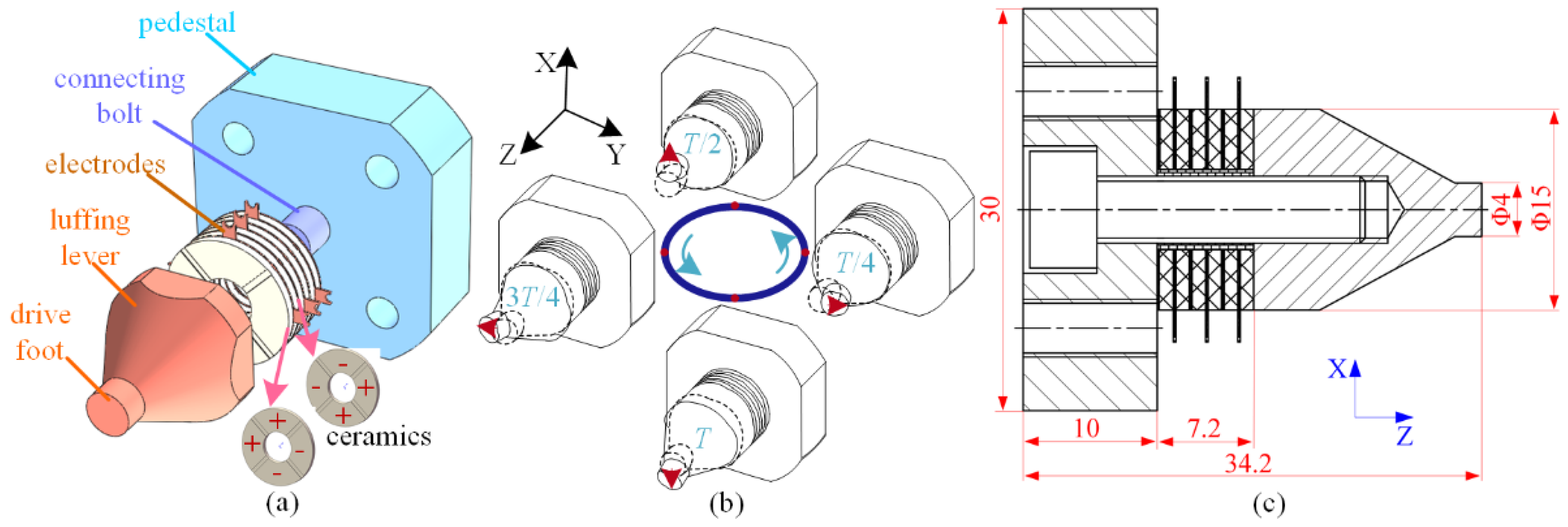
Figure 1. Actuator configuration and driving signal. (a) Basic structure. (b) The movement process of the stator. (c) The dimensions of the stator.
Actuators 11 00212 g001
Figure 2. Friction pair test experimental device.
Actuators 11 00212 g002
Figure 3. Characteristics of speed. (a) Relationship between the velocity and excitation voltage characteristics of the PUA. (b) Relationship between the output and preload characteristics of the PUA.
Actuators 11 00212 g003
Figure 4. Characteristics of the output force. (a) Relationship between the output force and excitation voltage. (b) Relationship between the output force and preload.
Actuators 11 00212 g004
Figure 5. Output speed stability experiment under long-term operation (500 m).
Actuators 11 00212 g005
Figure 6. Statistical histogram of the output velocity of different friction pairs: (a) ZrO2-Si3N4; (b) ZrO2-ZrO2; (c) ZrO2-GCr15; (d) 2A12-GCr15.
Actuators 11 00212 g006
Figure 7. Micro-mechanism analysis. (a) Relationship between pressuring depth and equivalent elastic modulus. (b) Stator and mover micro-drive model. (c) Horizontal movement speed of the driving point.
Actuators 11 00212 g007
Figure 8. Linear platform system. (a) Appearance top view. (b) Internal structure.
Actuators 11 00212 g008
Figure 9. Application test system and experimental results. (a) Experimental test system for the mechanical output characteristics of the linear motion platform. (b) Relationship between the speed and frequency. (c) Relationship between the speed and excitation voltage. (d) Relationship between the speed and load mass.
Actuators 11 00212 g009
Figure 10. Excitation signal and output displacement characteristics. (a) Sinusoidal alternating current pulse signal. (b) Output displacement under the pulse signal. (c) Output displacement under one signal.
Actuators 11 00212 g010
Table 1. Basic parameters of friction pair materials.
Material ParametersSi3N4ZrO2GCr15PEEK2A12
Density ρ (g/cm3)3.267.81.322.81
Elastic modulus E (GPa)3202102083.872
Poisson’s ratio0.260.30.30.40.33
Table 2. Variation in the output speed of different friction pairs.
Friction PairsRunning Distance (m)Initial Velocity (r/min)Peak Velocity (r/min)End Speed (r/min)
ZrO2-Si3N450410420395
ZrO2-ZrO240355390228
ZrO2-GCr1525285295258
2A12-Cr15130198218190
Table 3. Discrete analysis parameters of the output speed of actuators with different friction pairs.
Friction PairsVmSDCSSCVSK
ZrO2-Si3N4406.067.011.53 × 1050.017260.36572−0.50952
ZrO2-ZrO2307.3953.2988.5 × 1050.173360.08296−1.36762
ZrO2-GCr15265.5011.083.83 × 1050.04173−0.037112.60159
Table 4. Equivalent elastic modulus and friction coefficient of different friction pair combinations.
Friction Pair MaterialZrO2-Si3N4ZrO2-ZrO2ZrO2-GCr15ZrO2-PEEK
Equivalent elastic modulus E (GPa)126.8105104.53.73
Friction coefficient0.130.110.130.14
Table 5. Comparison between the proposed ultrasonic motor and some existing works.
ParametersThis WorkThe Motors in [33]The Motors in [34]The Motors in [35]
Total size (mm)30 × 30 × 34.22.6 × 2.6 × 2.285 × 6 × 155 × 26 × 14
Voltage (Vp-p)10015060400
Speed (mm/s)179.8140176.2159
Load mass (kg)23///
Resolution (µm)0.085///
Publisher’s Note: MDPI stays neutral with regard to jurisdictional claims in published maps and institutional affiliations.