Article

Design, Development and Experimental Assessment of a Cost-Effective Bellow Pneumatic Actuator

1
Faculty of Engineering, University of Rijeka, Vukovarska 58, 51000 Rijeka, Croatia
2
Centre for Micro- and Nanosciences and Technologies, University of Rijeka, Radmile Matejčić 2, 51000 Rijeka, Croatia
*
Author to whom correspondence should be addressed.
Actuators 2022, 11(6), 170; https://doi.org/10.3390/act11060170
Submission received: 24 May 2022 / Revised: 10 June 2022 / Accepted: 17 June 2022 / Published: 19 June 2022
(This article belongs to the Section Actuators for Robotics)

Abstract

:
Soft pneumatic actuators offer great advantages compared to rigid ones, particularly due to their compliant nature, which allows them to adapt to uncertainties in the environment. As such, they enable human-safe interactions and are often applied to various applications, such as for example, soft grippers or wearable devices for human motion assistance. The presented research describes the process of design, development and finally control of two cost-effective bellow pneumatic actuators. The properties of the developed devices are experimentally assessed by performing three different types of experiments. In a first instance, the testing of blocking force was performed, followed by experimental assessment of velocity-displacement characteristics, and finally, the dynamical properties for sinusoidally forced motion were examined. It was shown that the actuator can provide over 100 N force and assure a contraction ratio over 40% of its full length, with maximum velocity exceeding 60 mm/s. Experimental responses to a sinusoidally forced motion allowed establishing that no significant change due to the fatigue, creep and relaxation occur in material properties. Finally, the positioning performances of both developed devices were assessed by employing PID and LQR controllers which allowed their precise position control with fast responses and steady-state errors within the 0.2 mm margin. The performed research gives some insights into the future development of the pneumatically driven mechatronics systems used for position control.

1. Introduction

Compared to rigid ones, soft actuators offer significant benefits due to their flexible nature, lightweight properties and high specific power [1,2]. These devices are being progressively investigated by the research society while their usage spans to numerous interesting applications [3]. These applications are, for example, soft grippers used to manipulate delicate objects [4], devices used safely in close proximity to humans [5,6] or rehabilitation devices [7,8,9]. Moreover, such systems are increasingly being employed in the industrial environments especially for pick-and-place operations in cluttered surroundings [10,11].
A common way of actuation used in soft robotics is employing pneumatic muscle actuators (PMA) that use air as the working fluid. In this case, the energy of the compressed air converted to mechanical energy, causes displacement of the PMA. Based on their assembly, pneumatic actuators can generate linear, rotational or bending motion. Compared to traditional (rigid) pneumatic cylinders, soft pneumatic actuators can be developed from simple and low-cost materials and can work either with positive or negative pressure (sometimes even simultaneously) [12]. One of the main disadvantages of working with positive pressure (an example here is McKibben muscle) is the possibility of explosion of the structure. On the other hand, vacuum pneumatic actuators [13] eliminate the possibility of explosion, though there exists a possibility of implosion but with less severe consequences since the maximum working pressure is limited to p = −1 bar. In this frame, an interesting concept that can be employed to build a PMA device, is bellow type pneumatic muscle [14]. While for the previously mentioned McKibben PMA, the contraction ratio of 35% or less [15] is limited by the relatively low circular expansion of its structure, bellow-type pneumatic muscles allow contracting up to 90% of their full length. Another interesting approach that enables achieving large contraction ratios is origami-based vacuum PMA [16]. The listed properties of such structures allow their application in mechatronics positioning control systems with relatively large motion ranges.
In this paper, we present the design and fabrication of a simple vacuum-driven cost-effective bellow-type PMA, with a high contraction ratio and significant value of maximum force in relation to its dimension. While in recent research papers, authors designed, optimized and produced bellow-type PMAs by casting the elastomer or copolymer in molds [17,18], using a 3D printer with thermoplastic elastomer materials [19,20] or by using heat-shrinkable polymer tubes [21], we followed a simpler and cost-effective approach by using off-the-shelf components. We employed two universal cylindrical bellows usually used as protection of the front suspension on motorcycles. These components are produced from a thermoplastic vulcanizate elastomer (TPV) in large series by using an injection molding procedure. In the initial design phase, we performed the calculation of PMA based on the proven mathematical modeling [19,22] with the goal of obtaining the preliminary dimensions and operating parameters. One of the aims was to achieve lateral forces of up to approximately 100 N. Several design solutions were proposed, analyzed and evaluated, while two versions were finally adopted. The design approach followed in the presented research is graphically summarized in Figure 1.
It has to be mentioned here that the working principle of all artificial pneumatic muscle requires some spring effect for returning the muscle to its initial position. In references [23,24], the authors used the low-stiffness spring placed inside the thin muscle skin. In that way, the weight of the muscles is decreased but, on the other hand, the low-stiffened spring has the ability of radial deformation. Using the chosen rubber below, the spring effect was achieved by the bellow stiffness, which is itself sufficient for returning the PMA to the initial position. To eliminate the radial deformation of PMA and increase the value of force, we used rigid rings placed along the bellow length, using a similar idea as presented in [22]. This approach allowed increasing the force of the bellow PMA by increasing, at the same time, the spacing between the rings rather than increasing the overall diameter of the actuator. This resulted in a peak force that is much greater compared to a pneumatic cylinder with the same diameter. What is more, in [17,18] the authors confirmed that during the compression, points closer to the highest diameter of their proposed design were more likely to be damaged due to the presence of large stresses. Off-the-shelf components employed in this research were built to withstand large stress concentrations, which we additionally examined by assessing their mechanical and material properties. The proposed approach allows cost-effective, robust designs that can provide forces higher than 100 N, making it viable to be applied in industrial environments and robotics. Developed actuators were experimentally validated to determine the maximum values of operating parameters with respect to different values of vacuum and different loading conditions. Namely, the maximum blocking force, displacement-velocity dependence curve and sinusoidally forced motion responses were measured. Finally, the positioning performances by employing PID and LQR control approaches, were tested and compared.
The rest of the paper is organized as follows: In Section 2, materials and methods are described, including a brief introduction on the design and fabrication of the two presented PMA variants, followed by a description of the employed experimental apparatus and conducted preliminary tests. In Section 3, the experimental results on maximum blocking force, displacement-velocity dependence, sinusoidally forced motion responses and displacement control are presented. Finally, in Section 4, the main conclusions are drawn and future work is proposed.

2. Materials and Methods

In this section, a brief introduction on the design and fabrication of bellow PMAs is given, followed by the assessment of force vs. displacement dependence so as to determine the stiffness values. Furthermore, the overall experimental setup and its main components are presented, including preliminary experimental tests of the blocking force.

2.1. Design and Fabrication of Bellow PMA

The main idea behind the design presented in this research was to attain a simple, low-cost and easy-to-produce, but still robust and efficient bellow-type PMA, that is actuated by using negative pressure (Figure 1a). An off-the-shelves rubber cylindrical bellow, usually used as a protection of the front suspension on motorcycles, was chosen as a main component of the assembly. In order to achieve air-tightness, the holes at the end of the structure were covered by using 3D-printed lids that are also used for attaching the muscle (i.e., for the transmission of force in the axial direction) and to enable air supply. These components are depicted in Figure 1b. In a first instance, the diameters of the lids were different (Figure 1a); however, in order to enable higher forces, the rubber cylindrical bellow was shortened and adjusted so as to equalize the mentioned diameters. With the aim of constraining radial deformations, additional 3D-printed reinforcement rings were inserted along the inner side of the structure. It has to be noted here that the contraction ratio is limited by the thickness of the wall of the structure, i.e., by the length between two adjacent ribs during the full contraction of the muscle. Therefore, by adding more reinforcement rings, the total contraction ratio of the muscle is reduced; however, radial deformations are eliminated, and higher forces are achieved. Based on the above-described principle, two PMAs with slightly different construction parameters and material properties were fabricated for further investigation (Figure 2a). Table 1 summarizes main dimensions of both PMA versions.
In order to evaluate force vs. displacement dependence and to estimate stiffness parameters, experimental tests on both versions were performed by using the Shimadzu Autograph AGS-X micro tensile machine. The obtained results are shown in Figure 2b. As it can be seen from the results, the PMA2 has a higher stiffness value compared to the PMA1, which has longer length.

2.2. Experimental Apparatus and Preliminary Tests

The experiments were conducted at the Laboratory of hydraulic and pneumatic at the Faculty of Engineering, University of Rijeka. The experimental setup (Figure 3) is built from standard strut profiles and consists of Planet Air L-S50-25 compressor, FESTO VPPE-3-1/8-6-010 proportional pressure regulator and FESTO VN-05-H-T2-PQ1-VQ1-RQ vacuum generator. The measuring equipment used for control and data acquisition consists of: National Instruments NI myRIO 1900 device, Zemic H3G-C3-50kg-6B load cell, Schmalz VS VP8 SA M8-4 vacuum and pressure sensors, and Burster 8713-100 potentiometric displacement sensor. Additionally, analog manometers were used for validation of the results measured via vacuum and pressure sensors.
The bellow PMAs are mounted on the vertical strut profile using upper and lower holders, allowing also linear motion by sliding on the strut profile. The upper holder and the vertical profile are fixed by a screw connection, and the lower holder is movable but also has the possibility of being fixed. On the lower profile are affixed the load cell and the potentiometric displacement sensor. The vacuum generator function is based on the Venturi principle. Therefore, a proportional pressure regulator, with an operating range from 0 to 10 bar is used as an input pressure source. For the used FESTO vacuum generator, the input value of the air pressure ranging from 0 to 8 bar results in the vacuum range of 0 to −0.8 bar. It has to be noted that this principle is viable in the presented case, considering the relatively slow response time of the developed bellow PMA devices. The user application for data collection and control of the used proportional pressure regulator was developed using the LabVIEW programming environment.
The preliminary experimental results of evaluating the blocking force for both PMA versions, allowed establishing that PMA1 allows achieving a maximum force of 100 N, while PMA2 provides a maximum force of 130 N at a vacuum value of −0.75 bar in both cases. It has to be noted that these were absolute maximum values which were limited in the further experiments as it will be described in the following sections. Experimental investigation showed that PMA2 outperformed PMA1 in terms of maximum force, even though the stiffness of the bellow of PMA2 is in fact slightly higher. Such a result follows from the fact that PMA2 has a slightly larger diameter.
Experiments of determining the maximum force values are conducted in the next step, with blocked both ends of the bellow PMAs and a continuous increase of the vacuum in the 0 to −0.8 bar range. During the experiments, PMA1 showed an acceptable response for all vacuum values, while PMA2 started bending its ribs for vacuum values greater than −0.55 bar (Figure 4).
This resulted in the uncoupling of the bellow and the top lid as depicted in the last frame of Figure 4. With the attempt to resolve this issue, the bellow and the top lid were glued together; however, in that case, the two middle reinforcement rings slipped out from their corresponding bellows ribs, thus deforming the structure of the device and disabling the spring effect needed for returning the muscle to the initial position.

3. Experimental Results and Discussion

Once the final designs were obtained and the preliminary experimental validation was performed as described in the previous section, three sets of experiments were performed by employing the developed PMA devices. The first experiment, during which the device was fixed at its both ends, involved measurements of the maximum blocking forces at different positions within the working range and for different vacuum values. The second experiment was performed in a configuration, where the upper end of the bellow PMA was fixed, while the lower end with the load attached to its end, was left to move freely. This allowed the investigation of the time-dependence of the displacement for different values of vacuum and external loads. Finally, the third experiment was conducted by inducing sinusoidally forced motion so as to investigate the dynamical behavior of the devices as well as the influence of the repeatable movements on the structural and material properties of the developed muscles.

3.1. Experimental Assessment of Maximum Blocking Force

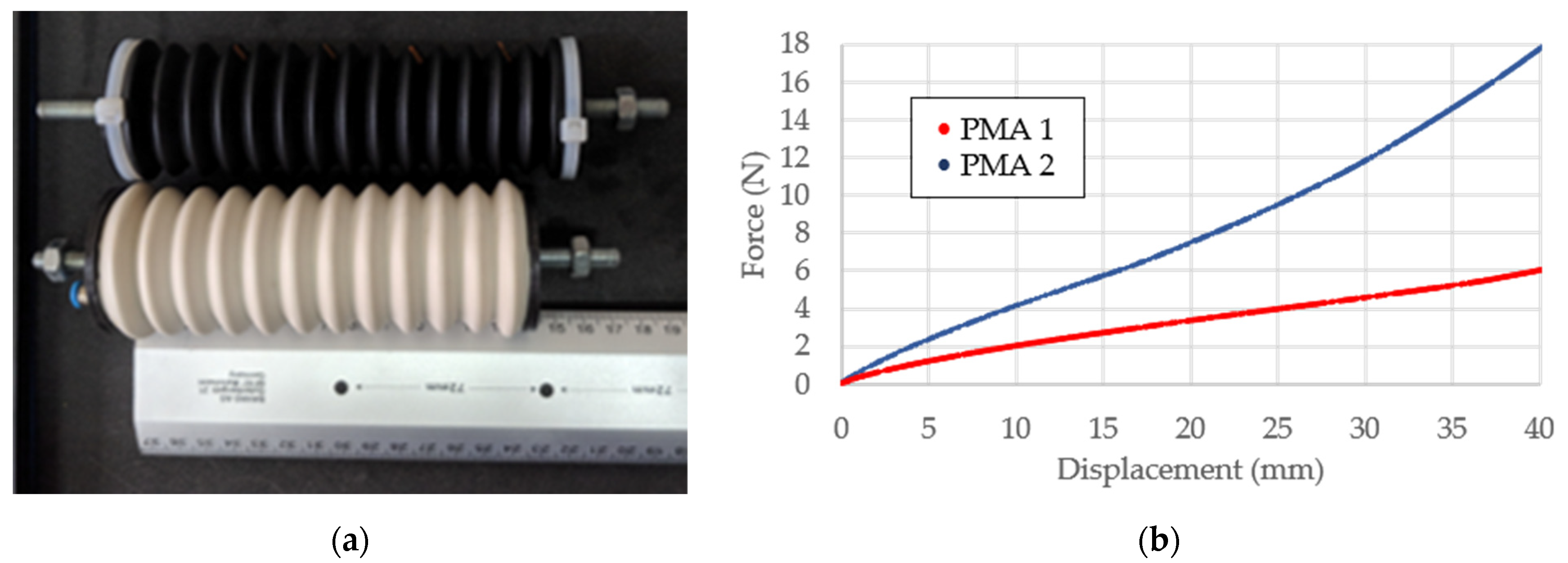
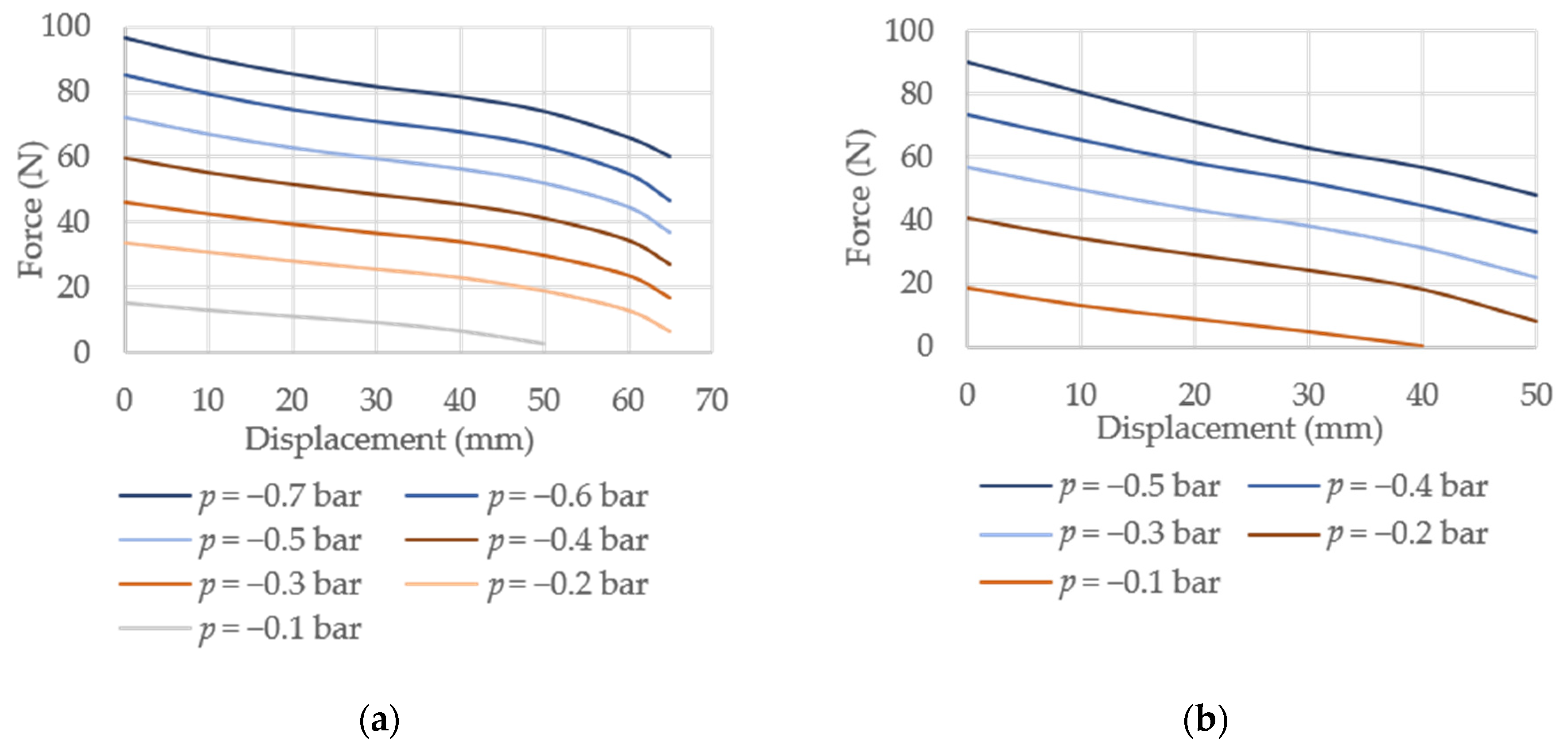
One of the important characteristics of a PMA device is the maximum force it can provide. This experimental investigation involves measuring the maximum blocking force for varying values of vacuum and different positions within the working displacement range. The actuators were placed on the testbench and fixed at their both ends. A load cell used for determining the force values was placed between the lower holder on the supporting structure and the actuator lower end. The experiments were performed for vacuum levels p ranging from −0.1 to −0.7 bar with an increment of Δp = −0.1 bar and displacements with a step of Δs = 10 mm, starting from the reference position. The reference position is the value of displacement for the unloaded actuator, i.e., the position with the maximum length between the lower- and upper-end lids of the actuator. The resulting curves, determined as an average of four repetitions of each measurement, are reported in Figure 5.
As expected, a decrease in the force is observed for displacements farther from the reference position, for all values of the vacuum. Please note that there are two types of forces acting on the structure: (1) following from Pascal’s law, the vacuum acting on the surfaces of the lids provides a constant value of the force for all displacement values, and (2) the vacuum effect on the surfaces of the ribs results in additional vertical and horizontal force components. This means that with increasing the displacement (shortening the structure of the actuator), the angle of the ribs is decreasing and so is the vertical component of the force. That is, with the larger displacement from the initial position, the opposing force generated by the structure of the bellow itself is increasing, resulting in a lower net force.
Comparing the amplitudes of the blocking force of both actuators for the same corresponding vacuum values, it can be seen that the PMA2 provides a higher maximum force. This is an outcome of its larger dimensions. In fact, in comparison with the PMA1, the area of the end lids of the PMA2 is 18% larger, and the value of the maximum blocking force is hence increased by approximately 23%. The maximum blocking force of PMA1 measured at the reference position is F = 96 N for the value of vacuum p = −0.7 bar, while the maximum blocking force of PMA2 determined at the reference position is F = 90 N for the value of vacuum p = −0.5 bar. Please note that the maximum vacuum value of PMA2 is limited to a value of −0.5 bar due to the deforming effect that appeared in the preliminary experiments described in Section 2.2.
From the resulting curves of the maximum blocking force it can be observed that the response of both devices is close to the linear behavior. In both cases, the largest deviation from the linear behavior occurs at the end of the displacement range. This follows from the fact that the ribs of the bellow and reinforcement rings come to a close contact as the actuator is reaching its maximum contraction. Overall, it is clear that the resistance force of the bellow has nonlinear characteristics, which affects the nonlinear dynamical behavior of this type of PMA. This effect is significantly seen in Figure 5a for the 60–65 mm displacement range in the case of PMA1. Additionally, during the experiment at vacuum of p = −0.1 bar, it was noticed that the blocking force was zero at displacements s = 50 mm and s = 40 mm for PMA1 and PMA2, respectively. This follows from the fact that at the low vacuum values, the resistance force of the bellow is greater than the actuator’s traction force itself.

3.2. Experimental Measurements of Displacement-Velocity Dependence

As opposed to the previously presented experiments, the experimental investigation presented in this section gives a little bit closer insight into the real working conditions under varying loading settings. The bellow pneumatic actuator was placed on the testbench in such a way that its upper end was fixed, while its lower end could move linearly. The experimental investigation was performed for vacuum values with an increment of Δp = −0.1 bar. All experimental investigations were conducted with the upper limit of vacuum set to a value of p = −0.7 bar for both actuators. Please note that the previously observed bending of the structure of PMA2 was prevented in this experiment by the fact that one of its ends could freely move, while the maximum external load was limited to 70 N.
The first set of tests was carried out without an external load—a minor resistance force caused by the returning spring in the potentiometric displacement sensor was neglected. The second experiment was performed for an external load of F = 25 N followed by the load of 70 N. The results of displacement over time for different loading conditions for both PMAs are shown in Figure 6.
From the results, it can be seen that there is a marked delay from the moment of activation of the actuator to the beginning of its displacement, for all vacuum values. This deadband is a result of time required to build-up vacuum in the system to a value which allows overcoming the resistance force of the actuator itself. As already pointed out, the vacuum was generated by a vacuum generator (ejector) and its alteration was achieved by altering the inlet value of pressure by a proportional-pressure regulator. The proportional-pressure regulator uses the principle of decreasing the flow area of the regulator to decrease the value of pressure, which directly affects the time required to achieve the needed value of vacuum. This is especially evident for the low vacuum set points. Moreover, the effect of air flow damping influences the time needed to achieve the maximum displacement of the actuators. This is particularly seen at the low vacuum value of −0.1 bar, where the maximum displacement of 30 mm was achieved in 30 s. The achieved maximum displacement for each actuator is the result of the vacuum value which acts on the end lids and the bellow ribs while generating the force opposing the direction of the load and bellow resistance force.
No-load experiments (Figure 6a) resulted in a maximum displacement of 68 mm for PMA1 and 55 mm for PMA2, both at the vacuum value of p = −0.7 bar. Considering the initial lengths of 160 and 140 mm for PMA1 and PMA2, respectively, the contraction ratio can be calculated dividing the measured maximum displacement by the initial actuator’s length. This calculation resulted in ε = 42.5% for PMA1 and ε = 40% for PMA2. It has to be noted here that the contraction ratio can be increased in the design phase by further reduction of the thickness of the inner rings and by increasing the distance between bellow ribs.
In contrast to the conditions without load, in the experiment with the 25 N load (Figure 6b) the lowest value of vacuum at which the actuator was able to perform movement was p = −0.2 bar. The deadband from the activation of the actuator to the beginning of its displacement was also present and was approximately the same as in the no-load conditions. Similar dynamical behavior can be observed with respect to the previous experiment, but the external load now limits further the maximum displacement, which is more noticeable at lower vacuum values. Both actuators achieved the maximum displacement at the vacuum value of p = −0.7 bar, which was 66 mm for PMA1 and 53 mm for PMA2, resulting in slightly lower contraction ratios, namely, ε = 41.3% for PMA1 and ε = 37.8% for PMA2.
Finally, with the 70 N loading setting (Figure 6c), PMA1 was not able to overcome the load for vacuum amplitudes lower than p = −0.5 bar and PMA 2 for amplitudes lower than p = −0.4 bar. During the experiment for vacuum value p = −0.7 bar, the bending of ribs appeared again, but did not permanently damage the actuator. From the results, it can be seen that a much longer deadband from the activation of the actuator to the beginning of its displacement is present, which is a result of the higher value of the load. Additionally, from the results, it can be noticed that more time is necessary to achieve a maximum value of displacement, especially for PMA1. The maximum value of displacement is much lower than in the previous experiments with a lower value of the external load. Both actuators achieved the maximum displacement at the vacuum value of p = −0.7 bar, which was 40 mm for PMA1 and 38 mm for PMA2, resulting in contraction ratios, ε = 25% for PMA1 and ε = 27% for the PMA2. From the results of the contraction ratios, it can be concluded that PMA1 achieved lower values than PMA2, which was not the case in previous experiments. The reason for that is the high value of load and lower dimensions of PMA1 in comparison to PMA2.
The above-described experiments allowed calculation of the time constants for different loading conditions. Time constants in this case represent the time from the beginning of actuation to the moment when the actuators achieve 63.2% of the target value. From the data shown in Table 2, as expected, it can be seen that with the increase in the vacuum amplitudes, the value of the time constant decreases, i.e., the response of the actuator becomes faster. What is more, it can be observed that the dynamical response of the PMA2 is slightly better for all values of vacuum. Additionally, compared with the results from Figure 2b, it can be noticed that a higher stiffness of the PMA2 bellow results in lower time constant values.
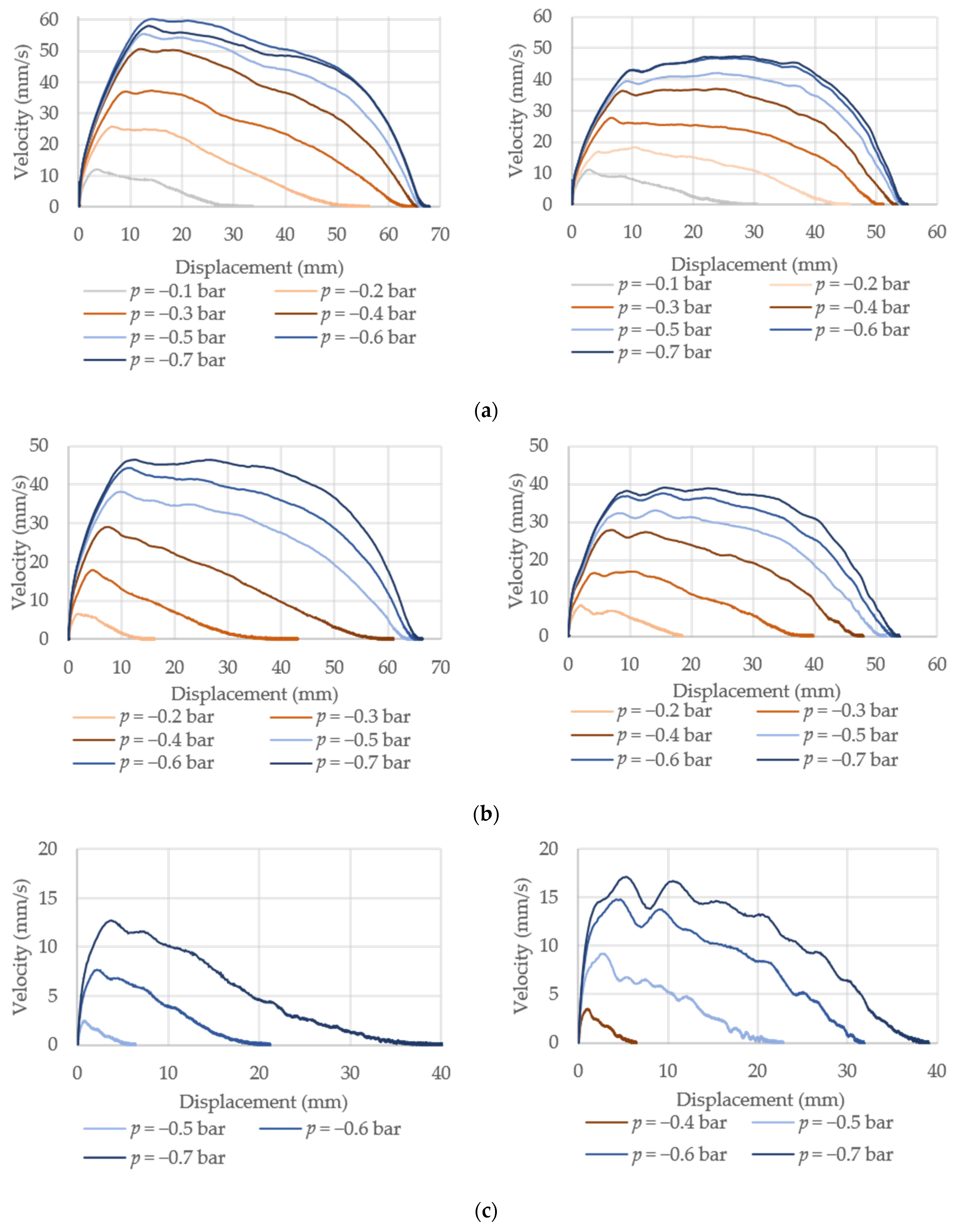
The open-loop velocity-displacement responses are recorded next as shown in Figure 7. From the results, it can be observed that for all vacuum values, both actuators reached their maximum velocities rapidly and then the velocity started decreasing as the actuator was reaching its maximum displacement.
Due to the fact that the velocity of the actuator is a function of the input flow, it can be noticed that at a lower value of pressure/vacuum, a lower maximum velocity is achieved. For PMA1 at a vacuum value of p = −0.7 bar, a maximum velocity v = 60 mm/s was achieved at displacement of 14 mm from the reference position, i.e., at 20% of its maximum displacement. For PMA2 at a vacuum value of p = −0.7 bar, a maximum velocity v = 47 mm/s was achieved at the displacement 28 mm away from the reference position, i.e., at 50% of its maximum displacement. Comparing the obtained results of the actuator velocity over displacement, it can be concluded that the actuators have slightly different dynamical characteristics as a result of the different dimensions and stiffness of the bellow material (see Figure 2b). The PMA2 reached the lower maximum velocity due to larger dimensions, and it achieved the maximum velocity at 50% of actuator’s maximum displacement as a result of the higher stiffness of the bellow material. By comparing the results of the velocity for different loading conditions, as expected, a decreasing trend of the velocity values can be observed with the increase in the load. In all cases PMA1 is able to achieve higher velocities through the whole displacement range in comparison to PMA2. Also, from the resulting velocity-displacement curves, a marked oscillatory behavior of the velocity can be observed, especially for higher loading conditions. Comparing the results of velocity for external loads of F = 0 N, F = 25 N and F = 70 N, it can be concluded that for higher values of loads, the velocity starts rapidly decreasing after reaching the maximum value. In the case of PMA1, decreasing of the velocity is smooth, while for PMA2, decreasing of the velocity shows oscillatory behavior. Based on the previous assumptions, it can be concluded that oscillatory velocity appeared after overcoming the inertial acceleration of the load, which resulted in a drop in velocity.

3.3. Experimental Results for Sinusoidally Forced Motion

Additional experiments were performed by exciting the system with a sinusoidal signal with the aim of investigating changes in the structural properties of the actuators due to the fatigue, creep and relaxation of material. By using the LabVIEW platform, a graphical interface was developed to generate a sinusoidal vacuum excitation signal with peak-to-peak amplitude of p = −0.5 bar and frequency f = 0.4 Hz. Each actuator was loaded with F = 25 N and subjected to a 10 min oscillatory motion. Within each period of the sine signal (T = 2.5 s), both actuators were moved from the initial position to a maximum achievable displacement and back to the reference position. The results of the displacement over time are shown in Figure 8. In the first 30 s of the experiment, the maximum value of displacement slightly increased and then remained constant until t = 350 s for PMA1 and t = 250 s for PMA2. Then, the displacement slightly increased (Δs ~ 1 mm) due to the inner heating of the material. Since bellow pneumatic actuators are soft actuators, such changes are certainly expected; however, these effects are not significant. Moreover, they can be relatively easily compensated for by appropriate feedback positioning control algorithms, as it will be briefly demonstrated in Section 3.4. Finally, and most importantly, fatigue, creep or relaxation of material were not observed.

3.4. Position Control of Developed Actuators

In this section, we finally demonstrate the precision positioning capabilities of the developed actuators. One of the demands in the majority of real-life mechatronics systems is the possibility of precision positioning with fast response time, over the whole working range of the system. In general, only closed-loop control systems can allow such properties, especially in the presence of external disturbances. In this work, we use two different control approaches for position control: a simple proportional-derivative controller (PID) and more complex linear quadratic regulator (LQR) [25,26].
First, the LabVIEW programming environment was used to develop and tune the PID controllers. The parameters of the controllers were tuned by using the Ziegler-Nichols method, which gave their rough estimation, and then fine-tuned by the trial and error procedure. Since the parameters for both actuators were very similar, the average values for both types were finally adopted. After a couple of tries with different combinations of PID terms, it was experimentally determined that for KP = 0.155, KI = 900 and KD = 60, the optimal responses were obtained. Obtained parameters were then used to perform point-to-point positioning experiments with setpoints spanning from 10 to 50 mm with a 10 mm increment. The examples of the achieved results for 20 and 40 mm references for both muscles are shown in Figure 9 (blue line). It was shown that a small steady state error of less than 0.2 mm is present within the whole working range for both devices. Furthermore, it was shown that there is no overshoot for the points that are up to 20 mm away from the reference position, while for the larger references, the overshoot value tends to increase.
With the aim of decreasing the overshoot, which appeared to be up to 10% for the highest references in the case of the previously described PID, the LQR controller was developed in the following step. Since a linear quadratic regulator represents a model-based control approach, in order to apply this type of control, it was first necessary to develop the models of each system. A data-driven approach is, therefore, used where each muscle was excited by using a random input signal in a form of Gaussian white noise with the amplitude in 0 to 10 V range, i.e., within the input voltage range of the used proportional valves. Measurements were repeated several times for each actuator and the Matlab identification toolbox was employed to derive the state-space representations. Both devices are represented as second-order systems. In order to find a stabilizing solution for each system and to solve the Riccati’s equation, which gives the vector with optimal LQR gains K, the idare Matlab function was used. The state matrix Q and input matrix R are determined by the trial-and-error procedure. Therefore, those variables were altered through many iterations until an acceptable system behavior was achieved. The final vector with gains was determined to be K = [−25,079 × 103 33,156 × 103] for both devices. Considering that the LQR algorithm does not have the ability to eliminate the steady-state error, a pregain G that multiplies the state variable only is additionally used. During the experiments, it was concluded that the value of the pregain is position-dependent, and it was interpolated by using a second-order curve:
G = 7 × 10 5 x 2 0.007 x + 0.2
The results of the positioning performances by employing the developed LQR controller for both versions of the actuators are depicted in Figure 9 (red lines) and compared with the previously used PID approach (blue lines).
It can be seen that the LQR approach allows achieving very small overshoot within the whole working range. Moreover, it can be observed that the steady-state error is very small and comparable to the case of PID control. The rise time parameter shows that the dynamics of the system is largely improved for smaller set points, while the same parameter is similar for higher references. On the other hand, it can be noticed that the settling time is also improved within the whole working range with respect to the PID approach.
The final step comprises analysis of the no-load settling time τs and rising time τr for both PMA versions (Table 3). The rise time is the time required for the PMA increase from 10% to 90% of the displacement setpoint, while the settling time is measured when the process value entered within ±2% of the target value. The results show, again, that in the whole reachable range of both devices, the LQR controller gives faster response with respect to the PID. The settling and rise time constants are increased with larger displacements, except in the case of the PID controller for a setpoint of 10 mm, where the largest values of these parameters are observed.

4. Conclusions

In the presented research, we show the procedure of the design and development of the vacuum pneumatic muscle actuator (PMA) with a bellow structure. The proposed design is characterized by a high contraction ratio and can generate high lateral forces considering its limited dimensions. The main idea behind the proposed research was to develop a cost-effective actuator by combining the use of an easily accessible off-the-shelf main body (bellow) and additive manufacturing techniques to build other necessary parts. We designed and developed two different variations with slightly different structural properties. By employing developed muscles, we performed thorough experimental investigation, which involved determining the maximum blocking forces, displacement-velocity dependence curves and sinusoidally forced motion responses. Experimental investigation showed that the maximum blocking forces that can be practically achieved without damaging the structure, are up to 96 N and 90 N for PMA1 and PMA2, respectively. Displacement-velocity curves showed that for the vacuum value of −0.7 bar, the maximum displacement was 68 mm for PMA1 and 55 mm for PMA2, which resulted in the contraction ratio of 42.5% for PMA1 and 40% for PMA2. Additionally, for the same value of vacuum, the maximum achievable velocities were 60 mm/s and 47 mm/s for PMA1 and PMA2, respectively. Additional sinusoidally forced cyclic experiments allowed establishing that fatigue, creep or relaxation of material were not observed for the developed designs. Finally, positioning control of the devices by employing PID and LQR algorithms showed that developed muscles can be used for performing real-world tasks with positioning precisions within 0.2 mm.
Future research efforts will be directed toward developing a 3-DOF motion platform by employing designs and control approaches presented in this work. Furthermore, we plan to investigate applying the same procedure to develop a soft pneumatic actuator that allows achieving angular motion.

Author Contributions

Conceptualization, G.G.; methodology, G.G., E.K., T.P.; software, T.P.; validation, G.G., E.K., T.P.; formal analysis, T.P.; investigation, T.P.; resources, G.G, E.K., T.P.; data curation, T.P.; writing—original draft preparation, G.G.; writing—review and editing, G.G. and E.K.; visualization, G.G., T.P.; supervision, G.G. and E.K.; funding acquisition, G.G. All authors have read and agreed to the published version of the manuscript.

Funding

This research received no external funding.

Institutional Review Board Statement

Not applicable.

Informed Consent Statement

Not applicable.

Acknowledgments

We are thankful to Samuel Pincin for performing some of the presented experiments and to Steven Nguyen for carefully reading the paper and giving comments.

Conflicts of Interest

The authors declare no conflict of interest.

References

  1. Kanno, T.; Ohkura, S.; Azami, O.; Miyazaki, T.; Kawase, T.; Kawashima, K. Model of a Coil-Reinforced Cylindrical Soft Actuator. Appl. Sci. 2019, 9, 2109. [Google Scholar] [CrossRef] [Green Version]
  2. Majidi, C. Soft Robotics: A Perspective—Current Trends and Prospects for the Future. Soft Robot. 2014, 1, 5–11. [Google Scholar] [CrossRef]
  3. Walker, J.; Zidek, T.; Harbel, C.; Yoon, S.; Strickland, F.S.; Kumar, S.; Shin, M. Soft Robotics: A Review of Recent Developments of Pneumatic Soft Actuators. Actuators 2020, 9, 3. [Google Scholar] [CrossRef] [Green Version]
  4. Su, H.; Hou, X.; Zhang, X.; Qi, W.; Cai, S.; Xiong, X.; Guo, J. Pneumatic Soft Robots: Challenges and Benefits. Actuators 2022, 11, 92. [Google Scholar] [CrossRef]
  5. Rus, D.; Tolley, M.T. Design, fabrication and control of soft robots. Nature 2015, 521, 467–475. [Google Scholar] [CrossRef] [Green Version]
  6. Nakayama, R.; Suzuki, R.; Nakamaru, S.; Niiyama, R.; Kawahara, Y.; Kakehi, Y. MorphIO: Entirely soft sensing and actuation modules for programming shape changes through tangible interaction. In Proceedings of the ACM Designing Interactive Systems 2019, DIS 2019, San Diego, CA, USA, 23–28 June 2019. [Google Scholar]
  7. Mikolajczyk, T.; Bednarczyk, K.; Mikolajczyk, A. Model of Human Hand Controlled Using Pneumatic Muscles. Appl. Mech. Mater. 2014, 555, 155–162. [Google Scholar] [CrossRef]
  8. Polygerinos, P.; Lyne, S.; Wang, Z.; Nicolini, L.F.; Mosadegh, B.; Whitesides, G.M.; Walsh, C.J. Towards a soft pneumatic glove for hand rehabilitation. In Proceedings of the 2013 IEEE/RSJ International Conference on Intelligent Robots and Systems, Tokyo, Japan, 3–7 November 2013; pp. 1512–1517. [Google Scholar]
  9. Aggogeri, F.; Mikolajczyk, T.; O’Kane, J. Robotics for rehabilitation of hand movement in stroke survivors. Adv. Mech. Eng. 2019, 11, 1687814019841921. [Google Scholar] [CrossRef]
  10. Kamenar, E.; Črnjarić-Žic, N.; Haggerty, D.; Zelenika, S.; Hawkes, E.; Mezić, I. Prediction of the behavior of a pneumatic soft robot based on Koopman operator theory. In Proceedings of the IEEE 2020 43rd International Convention on Information, Communication and Electronic Technology, Opatija, Croatia, 28 September–2 October 2020. [Google Scholar]
  11. Tanaka, J.; Ogawa, A.; Nakamoto, H.; Sonoura, T.; Eto, H. Suction pad unit using a bellows pneumatic actuator as a support mechanism for an end effector of depalletizing robots. ROBOMECH J. 2020, 7, 2. [Google Scholar] [CrossRef] [Green Version]
  12. Cao, M.; Zhu, J.; Fu, H.; Loic, H.Y.F. Response surface design of bellows parameters with negative pressure shrinkage performance. Int. J. Interact. Des. Manuf. (IJIDeM) 2022, 1–12. [Google Scholar] [CrossRef]
  13. Robertson, M.A.; Paik, J. New soft robots really suck: Vacuum-powered systems empower diverse capabilities. Sci. Robot. 2017, 2, 9. [Google Scholar] [CrossRef]
  14. Hashem, R.; Stommel, M.; Cheng, L.K.; Xu, W. Design and Characterization of a Bellows-Driven Soft Pneumatic Actuator. IEEE/ASME Trans. Mechatronics 2021, 26, 2327–2338. [Google Scholar] [CrossRef]
  15. Yang, H.D.; Greczek, B.T.; Asbeck, A.T. Modeling and Analysis of a High-Displacement Pneumatic Artificial Muscle with Integrated Sensing. Front. Robot. AI 2019, 5, 136. [Google Scholar] [CrossRef] [PubMed]
  16. Lee, J.; Rodrigue, H. Origami-Based Vacuum Pneumatic Artificial Muscles with Large Contraction Ratios. Soft Robot. 2019, 6, 109–117. [Google Scholar] [CrossRef] [PubMed]
  17. Joe, S.; Totaro, M.; Wang, H.; Beccai, L. Development of the Ultralight Hybrid Pneumatic Artificial Muscle: Modelling and optimization. PLoS ONE 2021, 16, e0250325. [Google Scholar] [CrossRef]
  18. Guo, N.; Sun, Z.; Wang, X.; Yeung, E.H.K.; To, M.K.T.; Li, X.; Hu, Y. Simulation analysis for optimal design of pneumatic bellow actuators for soft-robotic glove. Biocybern. Biomed. Eng. 2020, 9, 1359–1368. [Google Scholar] [CrossRef]
  19. Tawk, C.; Spinks, G.M.; Panhuis, M.; Alici, G. 3D Printable Linear Soft Vacuum Actuators: Their Modeling, Performance Quantification and Application in Soft Robotic Systems. IEEE/ASME Trans. Mechatronics 2019, 24, 2118–2129. [Google Scholar] [CrossRef]
  20. Dämmer, G.; Gablenz, S.; Hildebrandt, A.; Major, Z. PolyJet-Printed Bellows Actuators: Design, Structural Optimization, and Experimental Investigation. Front. Robot. AI 2019, 6, 34. [Google Scholar] [CrossRef] [Green Version]
  21. Zaghloul, A.; Bone, G.M. 3D Shrinking for Rapid Fabrication of Origami-Inspired Semi-Soft Pneumatic Actuators. IEEE Access 2020, 8, 191330–191340. [Google Scholar] [CrossRef]
  22. Felt, W.; Robertson, M.A.; Paik, J. Modeling Vacuum Bellows Soft Pneumatic Actuators with Optimal Mechanical Performance. In Proceedings of the 2018 IEEE International Conference on Soft Robotics, Livorno, Italy, 24–28 April 2018. [Google Scholar]
  23. Kim, S.; Lee, S.R.; Lee, S.; Lee, D.; Shin, D. Power-Efficient Soft Pneumatic Actuators Using Spring-Frame Collateral Compression Mechanism. Actuators 2022, 11, 76. [Google Scholar] [CrossRef]
  24. Kulasekera, A.L.; Arumathanthri, R.B.; Chathuranga, D.S.; Gopura, R.A.R.C.; Lalitharatne, T.D. A Low-Profile Vacuum Actuator (LPVAc) with Integrated Inductive Displacement Sensing for a Novel Sit-to-Stand Assist Exosuit. IEEE Access 2021, 9, 117067–117079. [Google Scholar] [CrossRef]
  25. Baćac, N.; Slukić, V.; Puškarić, M.; Štih, B.; Kamenar, E.; Zelenika, S. Comparison of different DC motor positioning control algorithms. In Proceedings of the IEEE 37th International Convention on Information and Communication Technology, Electronics and Microelectronics (MIPRO), Opatija, Croatia, 26–30 May 2014; pp. 1654–1659. [Google Scholar]
  26. Kazemi, S.; Hashem, R.; Stommel, M.; Cheng, L.K.; Xu, W. Experimental Study on the Closed-Loop Control of a Soft Ring-Shaped Actuator for In-vitro Gastric Simulator. IEEE/ASME Trans. Mechatron. 2022, 1–11. [Google Scholar] [CrossRef]
Figure 1. The process of development and experimental assessment of bellow PMAs: (a) 3D model of the design with its main elements; (b) used off-the-shelf bellow and parts developed by using additive manufacturing; (c) assembled devices; (d) device mounted and examined on the test-bench; and (e) experimental assessment of the operating parameters and position control.
Actuators 11 00170 g001
Figure 2. (a) Assembled bellow PMAs; (b) experimentally obtained force vs. displacement curves.
Actuators 11 00170 g002
Figure 3. Experimental setup.
Actuators 11 00170 g003
Figure 4. Deforming of the structure of PMA2 for vacuum values higher than −0.55 bar.
Actuators 11 00170 g004
Figure 5. Results of maximum blocking force: (a) PMA1; (b) PMA2.
Actuators 11 00170 g005
Figure 6. Displacement over time for PMA1 (left column) and PMA2 (right column): (a) without external load; (b) 25 N load; (c) 70 N load.
Actuators 11 00170 g006
Figure 7. Velocity vs. displacement curves for PMA1 (left column) and PMA2 (right column): (a) without external load; (b) 25 N load; (c) 70 N load.
Actuators 11 00170 g007
Figure 8. Experimental results for 10-min long sinusoidally forced excitation: (a) PMA1; (b) PMA2.
Actuators 11 00170 g008
Figure 9. Results of position control for PMA1 (left column) and PMA2 (right column) by employing PID (blue lines) and LQR controller (red lines): (a) 20 mm; (b) 40 mm reference.
Actuators 11 00170 g009
Table 1. Dimensions of the fabricated PMAs.
Versionh (mm)D1 (mm)D2 (mm)a (mm)b (mm)n (ribs)
Actuators 11 00170 i001115246351,51016
213250381,51112
Table 2. Time constants for different loading conditions (in seconds).
F = 10 (N)F = 25 (N)F = 70 (N)
p (bar)PMA1PMA2PMA1PMA2PMA1PMA2
−0.13.343.25----
−0.22.432.323.792.85--
−0.31.731.654.252.56--
−0.41.321.312.61.78-4.2
−0.51.241.231.841.65.714.05
−0.61.211.131.691.54.573.08
−0.71.21.121.571.484.472.97
Table 3. Settling and rising time constants for different set points (in seconds).
τs—PMA1τs—PMA2τr—PMA1τr—PMA2
Displ.
(mm)
PIDLQRPIDLQRPIDLQRPIDLQR
101.3250.4871.2250.4431.7 0.2341.8750.273
200.7250.5640.7250.5481.150.3630.8750.411
300.7750.670.7750.6680.680.6210.6750.54
400.8250.8160.8250.7930.750.750.70.675
500.91.0080.8750.9210.7550.9860.750.858
Publisher’s Note: MDPI stays neutral with regard to jurisdictional claims in published maps and institutional affiliations.

