Article

Influence of the Dynamic Effects and Grasping Location on the Performance of an Adaptive Vacuum Gripper

Department of Mechanics, Mathematics and Management, Polytechnic of Bari, Via Orabona 4, 70126 Bari, Italy
*
Author to whom correspondence should be addressed.
These authors contributed equally to this work.
Actuators 2022, 11(2), 55; https://doi.org/10.3390/act11020055
Submission received: 20 December 2021 / Revised: 7 February 2022 / Accepted: 10 February 2022 / Published: 12 February 2022
(This article belongs to the Special Issue Dynamics and Control of Robot Manipulators)

Abstract

:
A rigid in-plane matrix of suction cups is widely used in robotic end-effectors to grasp objects with flat surfaces. However, this grasping strategy fails with objects having different geometry e.g., spherical and cylindrical. Articulated rigid grippers equipped with suction cups are an underinvestigated solution to extend the ability of vacuum grippers to grasp heavy objects with various shapes. This paper extends previous work by the authors in the development of a novel underactuated vacuum gripper named Polypus by analyzing the impact of dynamic effects and grasping location on the vacuum force required during a manipulation cycle. An articulated gripper with suction cups, such as Polypus, can grasp objects by adhering to two adjacent faces, resulting in a decrease of the required suction action. Moreover, in the case of irregular objects, many possible grasping locations exist. The model explained in this work contributes to the choice of the most convenient grasping location that ensures the minimum vacuum force required to manipulate the object. Results obtained from an extensive set of simulations are included to support the validity of the proposed analytical approach.

1. Introduction

Robots are widely employed in many fields, from industrial to medical, and regardless of the specific application, all robots have an end-effector to interact with the environment. In factories or warehouses, common tasks such as grasping, holding, and manipulating objects are often performed by simple grippers with two fingers [1] able only to pinch with a small stroke. These grippers are simple and cheap, but they can grasp a narrow range of objects. Dexterous manipulators to handle generic objects is an old [2] but open problem; indeed, there are several challenges for researchers to design novel grippers to accommodate some tasks [3]. Several designs have been proposed for manipulators; a brief classification has been proposed in [4] where grippers are divided by possible configuration, actuation, application, and size. In [5], the authors presented a versatile gripper with three re-configurable fingers to switch between power and precision grasping to emulate human hand ability.
An interesting strategy to grasp an object is to control the adhesion; this can be achieved mainly with vacuum [6,7], electroadhesion [8], or a gecko-inspired structure [9,10]. Vacuum grippers have great potential; indeed, in the 2015 Amazon Picking Challenge, nine out of 26 groups used vacuum, including the winner [11,12]. In addition, a world leader robotic company (Boston Dynamics) is developing a vacuum gripper called Stretch able to move in a warehouse and equipped with a matrix of suction cups for pick-and-place. Other examples of vacuum grippers are the octopus-inspired grippers [13,14,15,16,17,18] that fall in the soft robotics, which allows high flexibility and adaptability at the expense of limited payload.
In previous work by the authors [19], a novel underactuated vacuum gripper was introduced and named as Polypus, after the contraction of POLYthecnic of Bari’s octoPUS. The system, which is equipped with suction cups, features high adaptability to objects thanks to different grasping strategies, e.g., unilateral and power, and a potential high payload for its modular design. Moreover, Polypus is outfitted with a locking device in the hinges to freeze relative angles between phalanxes once it assumed the shape of the object, increasing considerably the payload and making the actuation unnecessary during the hold. It is actuated by wires that pass through phalanxes and are fixed to the tip of the finger. The main novel contributions of this research lay in:
  • The extension of the Polypus grasping model from quasi-static to dynamic behavior, i.e., by taking into account the inertial effects connected with the manipulation task of an object under grasp.
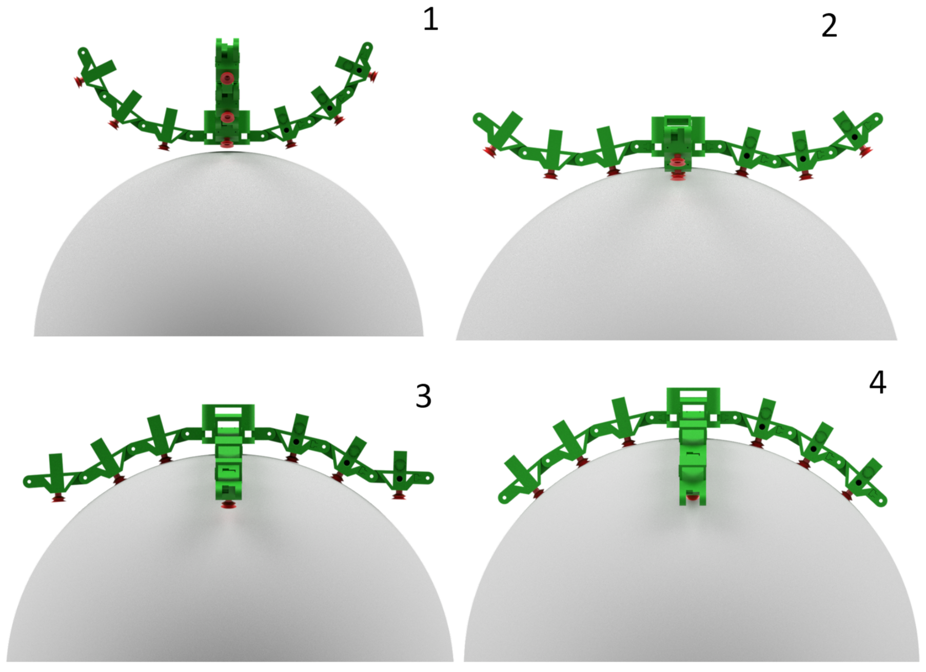
  • The assessment of the minimum vacuum force (MVF) required to manipulate a given object thorough different types of grasping configurations, in terms of contact points, e.g., placing the gripper in different positions of the object even with bending fingers to enhance the potentiality of Polypus compared to a fix matrix of suction cups.
The validity of the proposed analytical approach is verified via an extensive set of simulations of pick and place tasks with varying execution time and grasping location, and objects of different shapes and properties. Section 2 briefly describe the proposed gripper, Section 3 and Section 4, respectively, explain the theoretical model to predict the vacuum force needed to manipulate an object and provide simulation results. This work ends with a section that draws the main relevant conclusions.

2. Polypus Design

This section briefly recalls the main features of Polypus that is shown in Figure 1 as a CAD rendering. The interested reader is referred to [19] for an in-depth description of the system. The proposed gripper has a modular rigid framework made up of a palm and N fingers divided in M phalanxes; each phalanx is equipped with a suction cup. Polypus presents N × ( M 1 ) degrees of underactuation having only N actuators, one for each finger. As a typical solution to determine the sequential closure of phalanxes, torsional springs are foreseen in the hinges. Figure 2 illustrates the predetermined sequential closure on a sphere. The first step is of course the approach to the object (Figure 2, section 1). Once Polypus is close enough, actuators start pulling the wires and, being the elastic constant in the hinges closest to the palm the lowest, the first hinge rotates before all others (Figure 2, section 2). Once the first suction cup touches the object, the first hinge stops rotating, and the hinge with the second lowest elastic constant starts its approaching motion (Figure 2, section 3). This sequence continues until all the suction cups are in contact with the object (Figure 2, section 4). Another key feature of Polypus design is the existence of a locking device located in the hinges. Once the shape of the object has been assumed, this locking device makes Polypus a rigid body, significantly reducing the required vacuum force. An example of a manipulator with a locking device but without suction cups has been presented in [20].

3. Grasping Model

A model to evaluate the minimum vacuum force (MVF) is presented that explicitly takes into account the inertial effects connected to the manipulation task. The MVF is defined as the required force generated by each suction cup to avoid slipping and detachment during the manipulation. Since Polypus is modular, this model could be useful for example to assess the number of phalanxes to manipulate an object. Starting with an arbitrary number of phalanxes, the model provides the MVF; this value defines the dimension of suction cups. If the required suction cups are too big, the number of phalanxes should be increased. Moreover, different grasping locations could be compared to choose the most convenient. The following three subsections explain, respectively, the considered forces with relative assumptions, the trajectory of the manipulation, and the optimization framework.

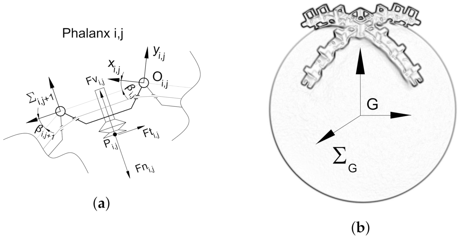
3.1. Model Description

Each phalanx is identified by a couple of indexes ( i , j ) where the first indicates the finger and the second indicates the phalanx number starting from the closest to the palm. For the hypothesis, the contact between a suction cup and the object is modeled as a point neglecting pressure distribution because the object is much bigger than the suction cup [21]. Another assumption is that the module of vacuum forces is the same for all the phalanxes i.e., the same suction cups and degree of vacuum.
For a generic phalanx, the forces and relevant points are shown in Figure 3a and defined as follows:
  • F v i , j i , j + 1 = 0 , F v , 0 T : The vacuum force is perpendicular to the suction cup pointing toward Polypus.
  • F n i , j i , j + 1 = 0 , F n i , j , 0 T : The normal contact force has the same direction of the vacuum force but the opposite verse.
  • F t i , j i , j + 1 = F t x i , j , 0 , F t z i , j T : The friction force has a generic direction in the contact plane with an upper limit fixed by friction constraint.
  • P i , j i , j + 1 = L 2 , h , 0 T : The contact point is in the middle of the suction cup. L is the length of the phalanx i.e., distance between two hinges, and h is the height of the phalanx i.e., distance between the line connecting two hinges and the contact point.
In the notation used above, the superscript indicates from which reference frame the quantity is seen, while the subscript indicates where the quantity is referred (e.g., P b a is the contact point of phalanx b seen from frame a). Knowing the pose of Polypus that is defined by relative angles between phalanxes (i.e., β i , j in Figure 3a), all the forces can be written in the object frame ( Σ G in Figure 3b) using homogeneous transformations. These forces and the relative location are useful to evaluate the equilibrium of the object, as will be formalized in the Section 3.3.

3.2. Trajectory Generation

As a running example throughout the paper, a common 2D trajectory is considered where the object under grasp is rotated by Polypus following a pure rotation, θ z , about the fixed point, C , connecting two target positions via a piecewise constant acceleration law. Figure 4 shows an example of this trajectory where the initial and final orientation of Polypus is respectively θ I = 0 and θ F = 90 deg. Given the total simulation time T and setting the ratio for the time sub intervals, e.g., T 0 = 0 , T 1 = 1 3 T , and T 2 = 2 3 T , Polypus starts with a null velocity and accelerates for a time defined by ( T 1 T 0 ) with a constant acceleration; then, it continues with a constant cruise velocity for ( T 2 T 1 ). The movement ends with a deceleration section ( T T 2 ) to reach zero angular velocity. Defining the acceleration as:
α a = 2 ( θ F θ I ) ( T 1 T 0 ) ( T + T 2 T 1 T 0 ) ,
the whole trajectory is the following:
α z ( t ) = α a for T 0 t < T 1 0 for T 1 t < T 2 α a T 1 T 0 T T 2 for T 2 t T
ω z ( t ) = α a ( t T 0 ) for T 0 t < T 1 α a ( T 1 T 0 ) for T 1 t < T 2 α a ( T 1 T 0 ) ( T t ) T T 2 for T 2 t T
θ z ( t ) = θ I + α a ( t T 0 ) 2 2 for T 0 t < T 1 θ I + α a ( T 1 T 0 ) ( t T 1 + T 0 2 ) for T 1 t < T 2 θ I + α a ( T 1 T 0 ) ( t T 1 + T 0 2 ( t T 2 ) 2 2 ( T T 2 ) ) for T 2 t T .
Lastly, the acceleration vector pertaining to the object center of mass, G , and gravity vector, g , can be expressed in the object frame ( Σ G ) as follows
G ¨ ( t ) = α z ( t ) G C , ω z ( t ) 2 G C , 0 T
g ( t ) = 9.81 sin θ z ( t ) , cos θ z ( t ) , 0 T m / s 2 .
Moreover, vectors with angular velocity and acceleration expressed in the object reference frame have to be set up, e.g., θ ˙ ( t ) = 0 0 ω z ( t ) T .
Although common 2D trajectory examples have been used in most of the simulations, Section 5 presents a use case where Polypus follows a 3D trajectory that mimics the movement of an object taken from a shelf and moved behind the robot similarly to the trajectory required by the Amazon picking challenge [11]. For the general case, i.e., θ ˙ ( t ) = ω x ( t ) ω y ( t ) ω z ( t ) T and θ ¨ ( t ) = α x ( t ) α y ( t ) α z ( t ) T , previous Equations (5) and (6) can be expressed as follows
G ¨ ( t ) = θ ¨ × ( G C ) + θ ˙ × [ θ ˙ × ( G C ) ]
g ( t ) = R 0 G 0 9.81 0 m / s 2
where R 0 G is the rotation matrix from the fixed reference frame to Σ G . The interested reader is referred to previous works, e.g., [22,23] for more details on the generation of operational space trajectories.

3.3. Optimization

The aim of the optimization is to find the MVF while performing the manipulation; indeed, the following optimization will be performed for each time t T with increment d t , and the time dependency will be omitted to simplify the notation. The cost function to be minimized is the module of the vacuum force F v ; recall that as mentioned in Section 3.1, the module is the same for all the phalanxes. The optimization variables are vacuum forces as well as contact forces, while the constraints are:
  • Equilibrium of the object forces and torques expressed in the frame attached to the object (i.e., Σ G in Figure 3b).
    i = 1 N j = 1 M [ ( F v i , j + F n i , j + F t i , j ) Q ( i , j ) ] + m g m G ¨ = 0
    i = 1 N j = 1 M [ ( r G , P i , j × F v i , j + r G , P i , j × F n i , j + r G , P i , j × F t i , j ) Q ( i , j ) ] I G θ ¨ θ ˙ × I G θ ˙ = 0
    where G ¨ and θ ¨ are, respectively, the linear and angular acceleration vector of the CoM, m is the mass of the object, I G is the inertia tensor relative to the CoM when expressed in Σ G , r G , P is the vector pointing in G with origin in P , and Q is a matrix to activate the suction cups, the element ( i , j ) is 1 if the suction cup ( i , j ) is in contact with the object; otherwise, it is 0.
  • Positiveness of F v i , j and F n i , j .
    F v 0
    F n i , j 0
  • Coulomb’s law of friction.
    F t x i , j 2 + F t z i , j 2 ( μ F n i , j ) 2
At the end of each optimization, the value of the MVF ( F v ) is saved in a vector and plotted as a function of time or angular position of Polypus in the next section.

4. Results

Simulations were performed using the optimproblem environment available under Matlab R2020b. The convex optimization problem was solved using the Interior point method where the initial guess was set equal to the solution found at the previous time. The manipulation of four different objects has been considered. In all simulations; it is assumed that Polypus fingers feature three phalanxes. Each phalanx has a length of 85 mm, a height of 45 mm, and a width of 40 mm. The palm is a square with a 100 mm side; therefore, the total tip to tip length of Polypus is 610 mm. For each object type, multiple simulations have been performed varying the speed of the manipulation (i.e., varying the inertial effect), the friction coefficient, and the grasping configuration of Polypus. One of the objectives of the simulations is to determine the extent of the vacuum force required to manipulate an object. In turn, this value can be compared with the maximum force a suction cup can generate. Considering as a reference the VASB Festo bellows and a degree of vacuum of −70 kPa, the maximum holding force results in 34 N for the 30 mm suction cup and 56 N for the 40 mm suction cup.

4.1. Case I: Flat Object—2 Fingers

For this case study, two fully extended fingers are considered to grasp a box with dimensions 61 × 50 × 10 cm and homogeneous mass distribution for a total weight of 5 kg. A schematic representation of the manipulation (i.e., θ z varies from 0 to 90 deg with a piecewise constant acceleration) is reported in the inset at the bottom of Figure 5; note that object proportions have been distorted for graphical purposes. The center of rotation (C) is 15 cm above the center of the palm. Figure 5 shows the MVF as a function of the angle θ z for different mean angular velocities; the friction coefficient is set equal to 0.6. The dotted line is a really slow manipulation considering a total rotation time (T) of 30 s. Here, dynamic effects are negligible, resulting in a peak of MVF of 15.89 N for θ z = 59 deg. On the other hand, the continuous line is a fast rotation (i.e., 0.6 s to span 90 deg) that requires almost doubled vacuum force (28.82 N). Jumps in the MVF come from the piecewise constant acceleration; indeed, the most critical part of the rotation is the beginning where inertia and weight forces are synchronized. In the intermediate section, where angular velocity is constant, there is only the centripetal contribution, which slightly increases the MVF. In the decelerating part, from 68 to 90 deg, inertia force is opposite to weight force, causing a drop in MVF. It should be noticed that at the end of the manipulation, 13.6 N of vacuum force are needed for a static hold (i.e., as soon as the acceleration becomes zero). Another set of simulations with the same object has been performed, varying the friction coefficient from 0.2 to 1. The manipulation time is 1.2 s, which includes 1 s for the rotation (equally divided in three sectors with constant acceleration) and 0.1 s of static holds at the beginning and the end. The MVF here is plotted in Figure 6 as a function of time in the upper plot, while the bottom section of Figure 6 plots the manipulation angle θ z , and the two graphs in the same figure share the x-axis. Seeing the MVF as a function of time allows the analysis of zero velocity sectors; thus, the increase of the vacuum force at the end of the manipulation becomes noticeable. As expected, lower friction coefficients require greater suction action, the maximum value of MVF is 42.8 N when μ is 0.2, 18.5 N for μ = 0.6 , and 14.8 N considering μ = 1 . Therefore, Fest VASB section cups of 30 mm are enough in all scenarios except when friction is 0.2.

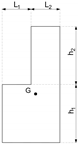
4.2. Case II: Trapezoid Object—2 Fingers

The second object is a trapezoid with sides 45 degrees bent, the bigger base is 81 cm in length, and the height is 38 cm. These dimensions lead to the same center of mass location of the previous case (i.e., 25 cm away from the upper side). In addition, in this case, two fingers are considered, and the mass of the trapezoid is the same as the box (5 kg). A schematic representation of the object and manipulation angle ( θ z ) is shown in the inset of Figure 7; the center of the rotation is 15 cm above the center of the palm. The same figure presents the value of the MVF considering a friction coefficient of 0.6 and different total rotation time (T), which implies diverse average rotation velocities. In the fastest case, the 90 deg rotation is achieved in 0.6 s, resulting in a maximum value of MVF of 25.3 N; if Polypus completes the rotation in 1.2 s, an MVF of 15.4 N is required, and 12.2 N is the peak of MVF for a very slow rotation i.e., 30 s. As in the previous case, the dynamic effects increase the required vacuum force mostly in the first part of the manipulation where Polypus is accelerating, while at the end of the rotation, the value of MVF is close to zero, being tangential acceleration and weight force opposite in direction. As soon as Polypus comes to a rest, an MVF of 4 N will be needed, as for the dotted line. The upper graph of Figure 8 plots results for different friction coefficients considering a rotation time of 1 s and static holds of 0.1 s. While the lower graph of Figure 8 illustrates the rotation angle θ z as a function of time, the two plots share the x-axis. Here, even when friction is 0.2, suction cups with a diameter of 30 mm would be enough. This consideration highlights the positive effect of grasping objects with low friction from two adjacent faces.

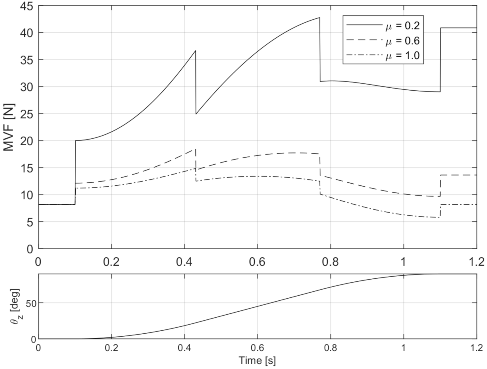
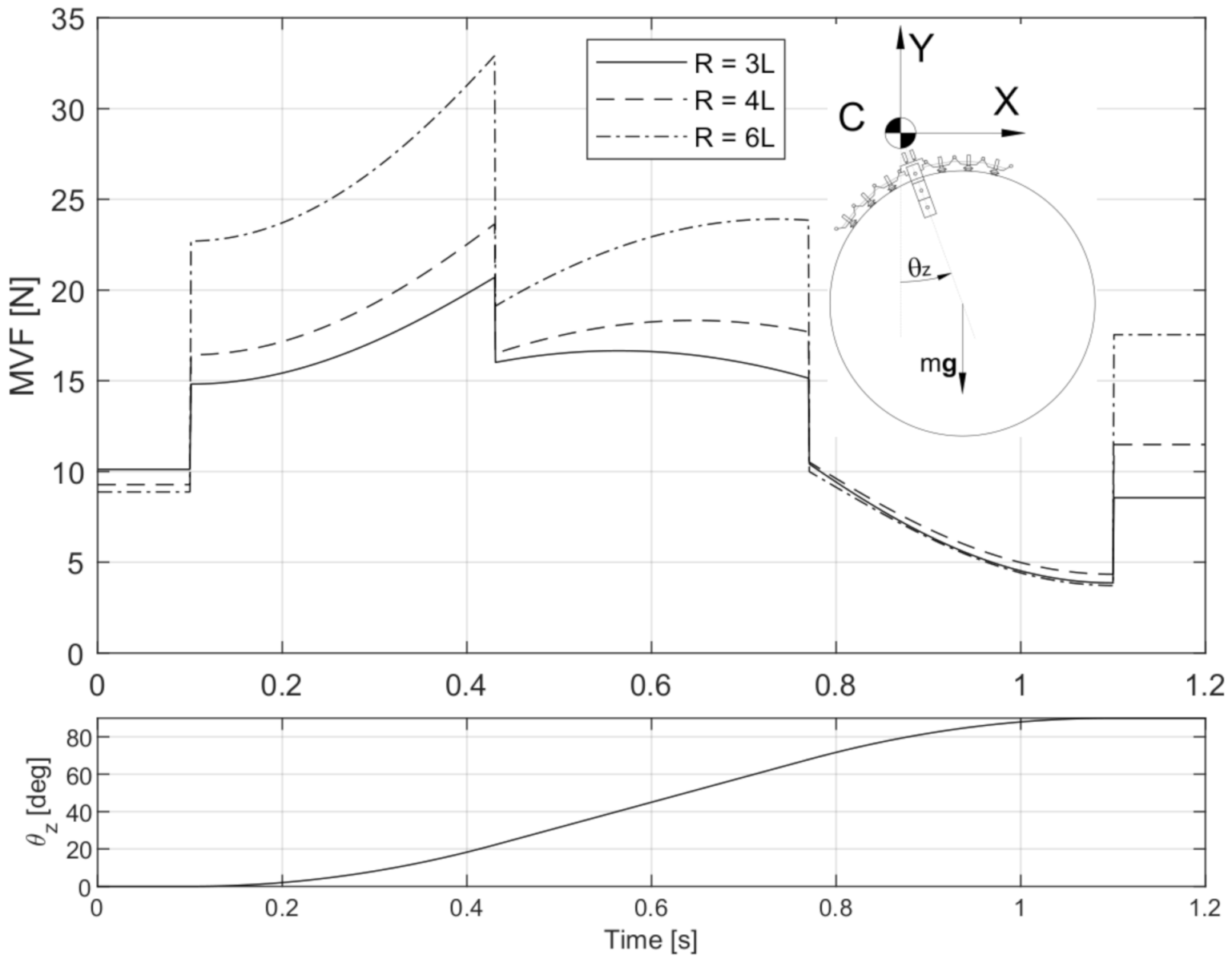
4.3. Case III: Sphere—Four Fingers

In this case, Polypus manipulates spheres of different sizes with four fingers. However, the mass of the spheres is always two times the mass of previous objects (10 kg). The CoM is in the middle of the sphere. Figure 9 shows from left to right rendered images of the sphere with radius 3, 4, and 6 times the phalanx length; in all the cases, the sphere is too big for power grasping, and thus, vacuum is always required. The friction coefficient is assumed to be 0.6. The upper graph of Figure 10 reports a schematic representation of the manipulation angle θ z in the upper-right corner and the MVF as a function of time. The center of rotation, (C), is 30 cm above the center of the palm. The bottom of Figure 10 shows the angle θ z as a function of time; the two graphs share the x-axis.
The diameter of the sphere affects the required vacuum force during the manipulation; the MVF increases with the radius of the sphere especially at the beginning of the manipulation. In the accelerating section, the inertia force is synchronized with the weight force, making the most critical angle the end of the acceleration ( θ z = 22 deg). The MVF associated with this angle is 32.6, 24.6, and 21.2 N considering the spheres respectively from the biggest to the smallest. In addition, in the middle section, where angular velocity is constant, the influence of the sphere diameter is noticeable, increasing the maximum registered value of MVF from 16 to 24 N. In the last manipulation section, the diameter has almost no influence on the MVF due to the cancellation of tangential effects being inertia and weight opposite in direction. To hold the object with θ z = 90 deg, the MVF almost doubled when considering the biggest sphere compared with the smallest. These results show the improvement in performance if the object is wrapped by the gripper, which is the main feature of Polypus where suction cups adhere to the object with different orientation. For R = 4 L and R = 3 L , 30 mm suction cups are sufficient, while for the biggest sphere ( R = 6 L ), suction cups of 40 mm diameter should be considered.

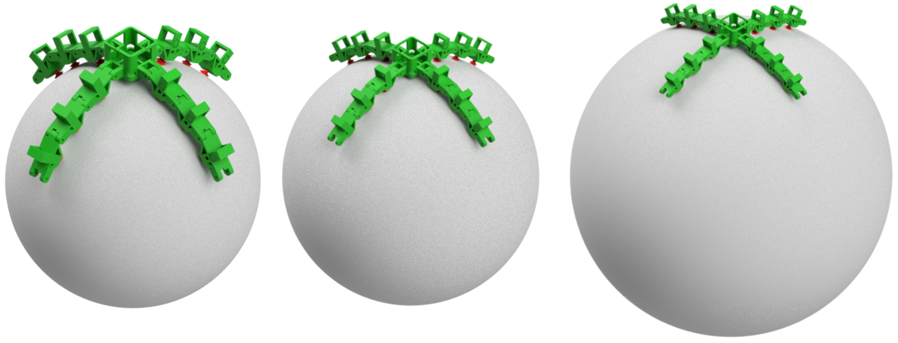
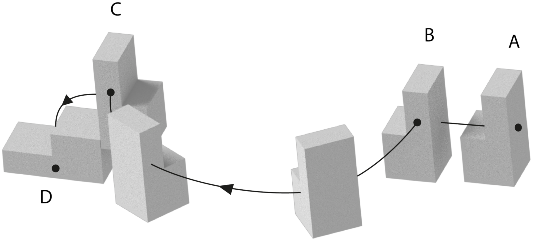
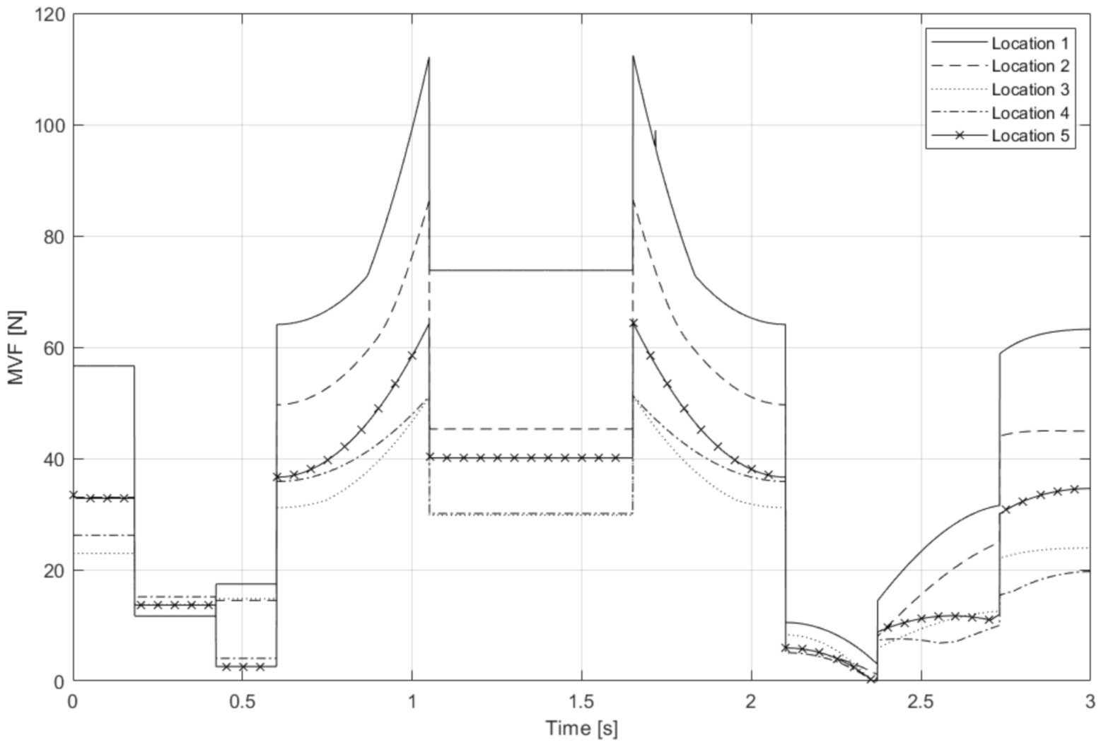
5. Optimization of the Grasping Location

The last set of simulations mimics a typical pick and place operation in a warehouse. Figure 11 explains the desired trajectory: starting from point A, there is a first translation of 1 m up to point B to remove the object from the shelf. Then, the object rotates (BC) about the vertical axis with a radius of 2 m. It is followed by a rotation of the wrist to place the object in point D rotated by 90 deg from the initial configuration. In this last sub-trajectory, a radius of 1 m is considered. This operation has been inspired by the short video that presents the Stretch on the Boston Dynamics website [24] and the Amazon Picking Challenge 2016 [11]. The same trajectory has been repeated considering five different grasping locations, as shown in Table 1, along with a side view of the object (bottom right) that shows the CoM location. The whole movement is achieved in 3 s, and the total time is divided in 20% for AB, 50% for BC, and 30% for CD. Figure 12 reports the value of the MVF as a function of the time. The most important aspect of this simulation is the difference between grasping locations. Here, we can see that the required vacuum force (i.e., the maximum value of MVF during the manipulation) has a strong dependence on the grip location. Locations 3 and 4 have almost the same MVF and are the best, followed by location 5, then location 2, whereas the worst is location 1. As expected, moving away from the CoM, the required MVF increases. It should be noticed that locations 3 and 4 can be achieved thanks to the specific feature of Polypus to have an articulated frame equipped with suction cups.

6. Discussion and Conclusions

This paper presents an analytical model to predict the vacuum force a gripper needs to grasp and rotate an object, including the inertia effect. Several simulations have been provided to show how the required vacuum force is affected by friction, manipulation time, and gripper location. Moreover, a brief comparison with a suction cup catalog has been included to indicate the suction cup dimension. From the results explained in the last section, a few considerations can be drawn. In the first two use cases, the grasped objects have the same mass and CoM distance from Polypus palm. In the first case, the gripper holds the object from only one face, while in the second case, Polypus adheres to two faces of the object bending one finger. Having suction cups in different planes is a unique feature of the proposed rigid gripper that allows a slight reduction of the vacuum force in fast manipulations with good friction coefficients (0.6) and a significant drop in the vacuum force while manipulating objects with low friction. Indeed, in the second case, 30 mm suction cups are enough even with low friction. On the other hand, in the first case, suction cups of at least 40 mm diameters are required for μ = 0.2 . In the third case, the object is a relatively big sphere, and it should be noticed that grasping the sphere could be a tricky task for grippers able only to power or that have a pinch grasping strategy as well as with an in-plane matrix of suction cups. Results from the last use case show that the proposed grasping model can be valuable to predict the best grasping configurations for objects with complex and irregular shapes. This can also be useful whenever specific requirements apply, namely the grasp can not be performed on one or more surfaces of the object that are delicate or fragile. Future research will investigate the impact on the grasping stability of the contact loss of one or more suction cups. One important development will also involve the experimental validation of the proposed approach via real experiments using a physical prototype of Polypus.

Author Contributions

All authors contributed equally to this work. All authors have read and agreed to the published version of the manuscript.

Funding

This research received no external funding.

Institutional Review Board Statement

Not applicable.

Informed Consent Statement

Not applicable.

Data Availability Statement

Data are available upon request to the corresponding author.

Conflicts of Interest

The authors declare no conflict of interest.

Abbreviations

The following abbreviations are used in this manuscript:
MVFMinimum vacuum force
CoMCenter of mass
F v i , j Vacuum force for the (i,j)-th phalanx
F n i , j Normal force for the for the (i,j)-th phalanx
F t i , j Tangential force for the (i,j)-th phalanx
P i , j Location of contact point of the (i,j)-th phalanx
r G , P i , j Position vector from P i , j to G

References

  1. Birglen, L.; Schlicht, T. A statistical review of industrial robotic grippers. Robot. Comput.-Integr. Manuf. 2018, 49, 88–97. [Google Scholar] [CrossRef]
  2. Piazza, C.; Grioli, G.; Catalano, M.; Bicchi, A. A century of robotic hands. Annu. Rev. Control Robot. Auton. Syst. 2019, 2, 1–32. [Google Scholar] [CrossRef]
  3. Watanabe, T.; Yamazaki, K.; Yokokohji, Y. Survey of robotic manipulation studies intending practical applications in real environments-object recognition, soft robot hand, and challenge program and benchmarking. Adv. Robot. 2017, 31, 1114–1132. [Google Scholar] [CrossRef]
  4. Samadikhoshkho, Z.; Zareinia, K.; Janabi-Sharifi, F. A brief review on robotic grippers classifications. In Proceedings of the 2019 IEEE Canadian Conference of Electrical and Computer Engineering (CCECE), Edmonton, AB, Canada, 5–8 May 2019; pp. 1–4. [Google Scholar]
  5. Borisov, I.I.; Borisov, O.I.; Gromov, V.S.; Vlasov, S.M.; Kolyubin, S.A. Versatile gripper as key part for smart factory. In Proceedings of the 2018 IEEE Industrial Cyber-Physical Systems (ICPS), St. Petersburg, Russia, 15–18 May 2018; pp. 476–481. [Google Scholar]
  6. Mantriota, G.; Messina, A. Theoretical and experimental study of the performance of flat suction cups in the presence of tangential loads. Mech. Mach. Theory 2011, 46, 607–617. [Google Scholar] [CrossRef]
  7. Mantriota, G. Theoretical model of the grasp with vacuum gripper. Mech. Mach. Theory 2007, 42, 2–17. [Google Scholar] [CrossRef]
  8. Guo, J.; Leng, J.; Rossiter, J. Electroadhesion technologies for robotics: A comprehensive review. IEEE Trans. Robot. 2019, 36, 313–327. [Google Scholar] [CrossRef]
  9. Glick, P.; Suresh, S.A.; Ruffatto, D.; Cutkosky, M.; Tolley, M.T.; Parness, A. A soft robotic gripper with gecko-inspired adhesive. IEEE Robot. Autom. Lett. 2018, 3, 903–910. [Google Scholar] [CrossRef]
  10. Song, S.; Majidi, C.; Sitti, M. Geckogripper: A soft, inflatable robotic gripper using gecko-inspired elastomer micro-fiber adhesives. In Proceedings of the 2014 IEEE/RSJ International Conference on Intelligent Robots and Systems, Chicago, IL, USA, 14–18 September 2014; pp. 4624–4629. [Google Scholar]
  11. Correll, N.; Bekris, K.E.; Berenson, D.; Brock, O.; Causo, A.; Hauser, K.; Okada, K.; Rodriguez, A.; Romano, J.M.; Wurman, P.R. Analysis and observations from the first amazon picking challenge. IEEE Trans. Autom. Sci. Eng. 2016, 15, 172–188. [Google Scholar] [CrossRef]
  12. Eppner, C.; Höfer, S.; Jonschkowski, R.; Martín-Martín, R.; Sieverling, A.; Wall, V.; Brock, O. Lessons from the amazon picking challenge: Four aspects of building robotic systems. In Proceedings of the 2016 Robotics: Science and Systems Conference, Ann Arbor, MI, USA, 18–22 June 2016. [Google Scholar]
  13. Bryan, P.; Kumar, S.; Sahin, F. Design of a soft robotic gripper for improved grasping with suction cups. In Proceedings of the 2019 IEEE International Conference on Systems, Man and Cybernetics (SMC), Bari, Italy, 6–9 October 2019; pp. 2405–2410. [Google Scholar]
  14. Xie, Z.; Domel, A.G.; An, N.; Green, C.; Gong, Z.; Wang, T.; Knubben, E.M.; Weaver, J.C.; Bertoldi, K.; Wen, L. Octopus arm-inspired tapered soft actuators with suckers for improved grasping. Soft Robot. 2020, 7, 639–648. [Google Scholar] [CrossRef] [PubMed]
  15. Mazzolai, B.; Mondini, A.; Tramacere, F.; Riccomi, G.; Sadeghi, A.; Giordano, G.; Del Dottore, E.; Scaccia, M.; Zampato, M.; Carminati, S. Octopus-Inspired Soft Arm with Suction Cups for Enhanced Grasping Tasks in Confined Environments. Adv. Intell. Syst. 2019, 1, 1900041. [Google Scholar] [CrossRef] [Green Version]
  16. Takahashi, T.; Suzuki, M.; Aoyagi, S. Octopus bioinspired vacuum gripper with micro bumps. In Proceedings of the 2016 IEEE 11th Annual International Conference on Nano/Micro Engineered and Molecular Systems (NEMS), Sendai, Japan, 17–20 April 2016; pp. 508–511. [Google Scholar]
  17. Wei, Y.; Zhang, W. OS hand: Octopus-inspired self-adaptive underactuated hand with fluid-driven tentacles and force-changeable artificial muscles. In Proceedings of the 2017 IEEE International Conference on Robotics and Biomimetics (ROBIO), Macau, Macao, 5–8 December 2017; pp. 7–12. [Google Scholar]
  18. Pi, J.; Liu, J.; Zhou, K.; Qian, M. An Octopus-Inspired Bionic Flexible Gripper for Apple Grasping. Agriculture 2021, 11, 1014. [Google Scholar] [CrossRef]
  19. Maggi, M.; Mantriota, G.; Reina, G. Introducing POLYPUS: A novel adaptive vacuum gripper. Mech. Mach. Theory 2022, 167, 104483. [Google Scholar] [CrossRef]
  20. Aukes, D.M.; Heyneman, B.; Ulmen, J.; Stuart, H.; Cutkosky, M.R.; Kim, S.; Garcia, P.; Edsinger, A. Design and testing of a selectively compliant underactuated hand. Int. J. Robot. Res. 2014, 33, 721–735. [Google Scholar] [CrossRef]
  21. Mantriota, G. Optimal grasp of vacuum grippers with multiple suction cups. Mech. Mach. Theory 2007, 42, 18–33. [Google Scholar] [CrossRef]
  22. Paul, R. Manipulator Cartesian path control. IEEE Trans. Syst. Man Cybern. 1979, 9, 702–711. [Google Scholar] [CrossRef]
  23. Farin, G. Curves and Surfaces for CAGD: A Practical Guide; Morgan Kaufmann Publishers: San Francisco, CA, USA, 2001. [Google Scholar]
  24. Boston Dynamics. Available online: https://www.bostondynamics.com/products/stretch (accessed on 20 January 2022).
Figure 1. Rendering of the proposed vacuum gripper Polypus.
Actuators 11 00055 g001
Figure 2. Example of sequential closure with a sphere having a radius four times the phalanx length.
Actuators 11 00055 g002
Figure 3. Schematic representation of reference frames used to develop the theoretical model with reference to the single phalanx (a) and object under grasp (b).
Actuators 11 00055 g003
Figure 4. Example of trajectory for the manipulation.
Actuators 11 00055 g004
Figure 5. Minimum vacuum force required to rotate a box expressed as a function of the inclination angle θ z that is shown in the bottom inset. Different curves refer to increasing time T, i.e., the total time used for the rotation as defined in Equations (2)–(4).
Actuators 11 00055 g005
Figure 6. (Upper plot): Minimum vacuum force required during the rotation of a box as a function of time. Results are presented for different friction coefficients. (Bottom plot): Inclination angle θ z . Note that the two plots shares the x-axis.
Actuators 11 00055 g006
Figure 7. Minimum vacuum force required during the rotation of a trapezoid object as a function of the angle θ z that is shown in the inset. Different curves refer to increasing time T, i.e., the total time used for the rotation, as defined in Equations (2)–(4).
Actuators 11 00055 g007
Figure 8. In the upper plot, minimum vacuum force required during the rotation of a trapezoid object as a function of time; results are presented for different friction coefficients. In the bottom plot rotation angle θ z , the two plots shares the x-axis.
Actuators 11 00055 g008
Figure 9. Rendered images of spheres, from left to right the diameter of the sphere is respectively three, four, and six times the length of Polyps phalanx.
Actuators 11 00055 g009
Figure 10. (Upper plot): Minimum vacuum force required during the manipulation of spheres with different dimension as a function of time. (Bottom plot): Angle θ z that defines the rotation of the manipulation.
Actuators 11 00055 g010
Figure 11. Schematic representation of the trajectory followed by the irregular prism. It simulates a robot that picks an object from a shelf (AB); then, after a rotation of the whole robot (BC), the object is placed rotated 90 degrees (CD).
Actuators 11 00055 g011
Figure 12. Minimum vacuum force required during the trajectory of Figure 11 as a function of time.
Actuators 11 00055 g012
Table 1. This table reports the grasping locations used with the irregular rectangular prism. On the right side of the bottom row, there is a schematic representation that shows the center of mass G and the object dimensions ( L 1 = L 2 = 34 cm, h 1 = h 2 = 68 cm, the width of the object is 68 cm).
Location 1Location 2Location 3
Actuators 11 00055 i001 Actuators 11 00055 i002 Actuators 11 00055 i003
Location 4Location 5Object Geometry
Actuators 11 00055 i004 Actuators 11 00055 i005 Actuators 11 00055 i006
Publisher’s Note: MDPI stays neutral with regard to jurisdictional claims in published maps and institutional affiliations.

