Article

Electrical Properties of Li+-Doped Potassium Sodium Niobate Coating Prepared by Supersonic Plasma Spraying

1
School of Materials Science and Engineering, Xi’an University of Technology, Xi’an 710048, China
2
National Key Laboratory for Remanufacturing, Army Armored Forces Institute, Beijing 100072, China
*
Authors to whom correspondence should be addressed.
Actuators 2022, 11(2), 39; https://doi.org/10.3390/act11020039
Submission received: 30 December 2021 / Revised: 18 January 2022 / Accepted: 19 January 2022 / Published: 26 January 2022

Abstract

:
The current work aims to compare the effects of systematic A-site substitutions on the electrical properties of potassium sodium niobate (KNN)-based coating. The A-site elements were replaced by Li+ to form (K0.4675Na0.4675Li0.065) NbO3 (KNLN). The pure KNN coating and the Li+-doped potassium sodium niobate (KNLN) coating with dense morphology and single perovskite structure were successfully prepared by supersonic plasma spraying, and the phase composition, microscopic morphology and electrical properties of the two coatings were compared and analyzed in detail by XRD, XPS, three-dimensional morphology and SEM on an Agilent 4294A (Santa Clara, CA, USA) and FE-5000 wide-range ferroelectric performance tester. The results show that: as the polarization voltage increases, the pure KNN coating is flatter and fuller, but the leakage current is large. The KNLN coating has a relatively long hysteresis loop and is easily polarized. The domain deflection responds faster to the external electric field, and the resistance of the domain wall motion to the external electric field is small. The dielectric constant of KNLN coating is 375, which is much higher than that of the pure KNN coating with 125, and the dielectric loss is stable at 0.01, which is lower than that of pure KNN coating at 0.1–0.35. This is because Li+ doping has successfully constructed a polycrystalline phase boundary in which O-T phases coexist, and has higher dielectric properties, piezoelectric properties and ferroelectric properties. At the same time, due to the high-temperature acceleration process in supersonic plasma spraying, the violent volatilization of the alkaline elements Li+, Na+ and K+ leads to the presence of oxygen vacancies and part of Nb4+ in the coating, which seriously affects the electrical properties of the coating.

1. Introduction

At present, the research field of structural health monitoring is very wide, and it is widely used in various structures. Piezoelectric materials are one of the important materials for structural health monitoring. The research on piezoelectric materials has been more in-depth, and the preparation technology of piezoelectric materials is also relatively perfect. Among them, Thermal spraying is a mature technology for manufacturing inorganic material coatings in industry. Compared with other coating methods such as physical vapor deposition. (PVD), chemical solution deposition (CSD), screen printing and aerosol deposition (AD), thermal spraying has obvious advantages, such as high productivity, large thickness range, large area and less limited substrate selection. However, the thermal spraying process is mainly used in the preparation of thermal barrier and wear-resistant coatings, and few people use it on new functional materials. Smart sensor coating materials are one of the uses, and the piezoelectric coating is its main content. As a kind of thermal spraying technology, supersonic plasma spraying technology can quickly impact the powder on the substrate so that the probability of phase change in the process from the powder to the coating is reduced, and to make the prepared coating maintain the excellent performance of the powder with the greatest probability, which is particularly important for the preparation of smart sensor coatings
The research on piezoelectric materials has been relatively in-depth, and lead-based piezoelectric ceramic materials, mainly PZT, have always occupied the mainstream of the market due to their excellent piezoelectric properties. However, the piezoelectric ceramic coating prepared by thermal spraying has almost no piezoelectric properties due to the generation of some second phases. Although the perovskite phase can be strengthened by heat treatment after spraying and the second phase can be reduced, it cannot be completely eliminated [1,2]. According to reports [3,4], the d33 of PZT coatings prepared by plasma spraying is only 0.47–1.1 pC/N. By switching to a more complex supersonic plasma spraying technology, a single-phase, low porosity and reduced physical defective PZT-based coating is prepared, and the piezoelectric coefficient reaches 61 pC/N. Therefore, even though the PZT piezoelectric ceramic material has high piezoelectric performance, its coating is easily decomposed, resulting in its low piezoelectricity. However, on the other hand, the supersonic plasma spraying technology can minimize the volatilization of components and the generation of the second phase, so as to obtain higher piezoelectric performance. Another limitation on the development of PZT piezoelectric coatings is the material itself, because it contains more than 60% of the volatile heavy metal lead. In high-temperature thermal spraying, a large amount of lead is volatile, which is toxic to the environment and endangers human health.
Since 2000, people have been trying to prepare lead-free piezoelectric ceramic coatings by thermal spraying. There are relatively many research works on BT-based coatings, but they mainly focus on the study of dielectric properties. According to reports [5], the addition of ZnO can reduce microcracks and porosity, improve the molten state, and increase the amorphous phase. But the current research [6] achieved piezoelectric performance of d33 < 15 pC/N. BT’s low piezoelectric coefficient and low Curie temperature limit its piezoelectric applications. In the past 10 years, a lot of work has been done in the research and development of high-performance bulk ceramics of lead-free piezoelectric materials, and significant progress in performance improvement has been made. Some lead-free piezoelectric materials that have been reported are comparable to PZT lead-based piezoelectric ceramic materials, such as KNN-based piezoelectric ceramics.
KNN-based piezoelectric ceramics are among the most widely studied lead-free piezoelectric systems because of their large piezoelectric coefficient and high Curie temperature. Through proper composition design and crystal phase adjustment, the best electrical performance can be obtained at the polycrystalline phase boundary (PPT). Current research mainly focuses on bulk ceramics and thin films, and has made significant progress [7,8,9,10], however, there is not much progress in forming piezoelectric ceramic coatings by thermal spraying.
The latest research is from the Kui Yao team of Singapore National University. They were the first to prepare KNN-based piezoelectric coatings and BNT coatings with a dense morphology and a single perovskite phase by supersonic plasma spraying [11,12]. The powders were added with 10% mol of Na, K and Bi respectively, and the prepared coatings were heat-treated to further improve the crystallinity and electrical properties, and the piezoelectric coefficients reached 112 pC/N and 50 pC/N, respectively. The KNN-based piezoelectric coating is about an order of magnitude higher than other thermal spraying lead-free piezoelectric ceramic coatings reported in the literature. The high piezoelectric coefficient is caused by the single-phase perovskite structure with high crystallinity obtained in the KNN-based coating. The BNT coating obtains a polymorphic phase boundary in which rhombohedral and tetragonal phases coexist, and all the amorphous phases are crystallized after heat treatment, and excellent electrical properties are obtained [13]. Therefore, it is obviously feasible to obtain the polycrystalline phase boundary by ion doping in order to improve its electrical properties.
Thus, in this paper attempts have been made to improve the electric performance of KNN coating via Li+ addition. The current investigation aims to compare the effects of systematic A-site substitutions on the electrical properties of potassium sodium niobate (KNN)-based coating. The A-site elements were replaced by Li+ to form (K0.4675Na0.4675Li0.065) NbO3 (KNLN). The phase composition, microscopic morphology and electrical properties of the KNN and KNLN coatings were compared. We suggested that the enhancement in electrical properties was not only attributed to the decreasing of unmelted particles but also the result of doping behavior.

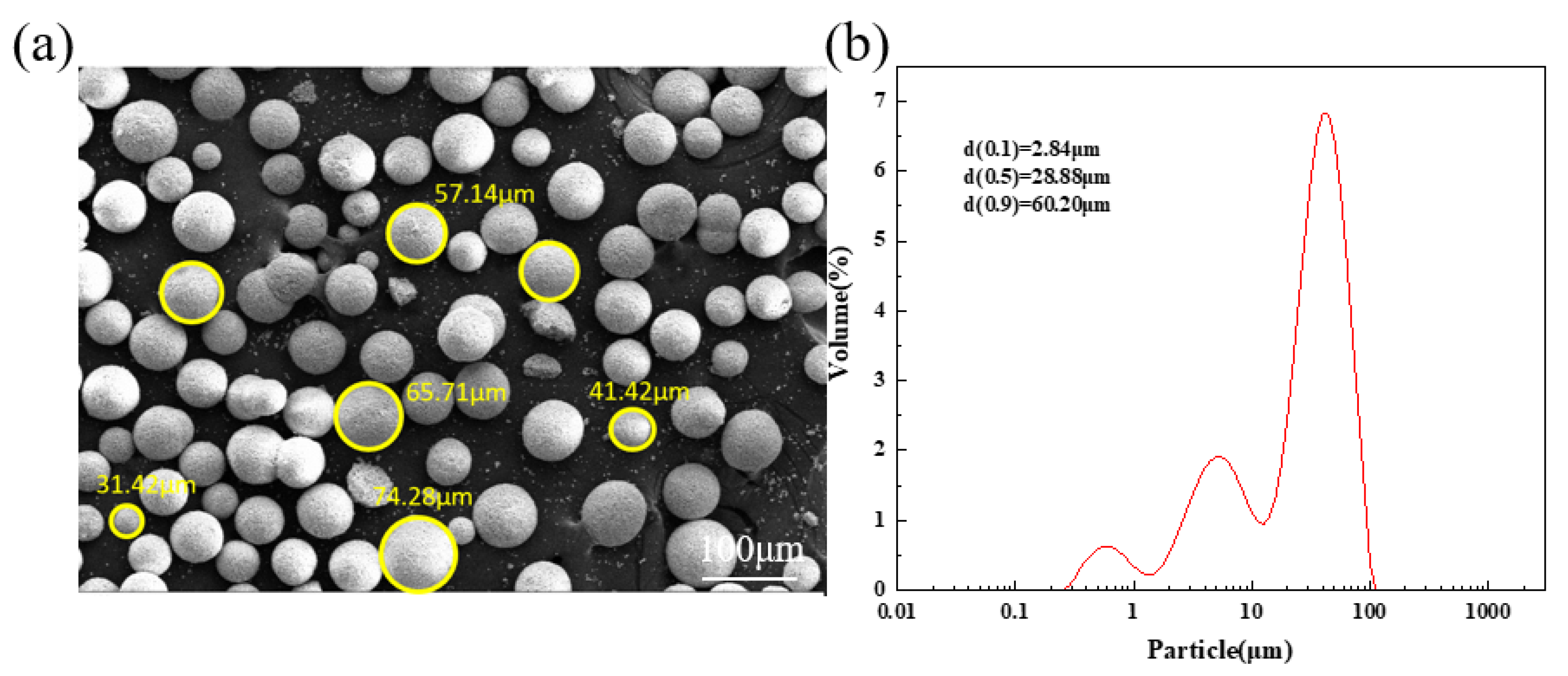
2. Experimental Procedures

2.1. Materials and Methods

In this experiment, potassium sodium niobate (K0.5Na0.5NbO3) powder and lithium potassium sodium niobate (K0.4675Na0.4675Li0.065NbO3) powder (Quanzhou Qijin New Material Technology Limited Company, Quanzhou, China) were used as spray powders. Among them, in order to effectively reduce the volatilization of sodium potassium in the potassium sodium niobate-based coating, 10 mol% of excess Na and K were introduced in the preparation process of both powders In order to make the powder suitable for plasma spraying, the sintered potassium sodium niobate-based powder was bonded with polyvinyl alcohol and dried in a centrifugal spray dryer at a speed of 13,000 r/min to obtain the required particle size distribution. As shown in Figure 1a, most of the particle sizes are concentrated in 50μm, and it can be seen from Figure 1b that the average particle size is 28.88μm, because of the better sphericity, it can show good supply performance during the plasma spraying process.
Based on the tank gear as the service object, 45# steel with a size of 25 mm × 20 mm × 4 mm was selected as the base. It was cleaned in advance with alcohol solution to remove oil and grease on the surface of the base. Sandblasting with alumina particles can remove oxides and other impurities, increase the surface roughness of the substrate, and facilitate the deposition of ceramic particles.
Before spraying, we preheated the 45# steel substrate to 90–110 °C by plasma jet without carrying powder, and used a pyrometer (RAYRPM30L3U, Raytek, Santa Cruz, CA, USA) to measure the preheating temperature. The preheating time was about 10 seconds. A supersonic plasma spray system was used to spray potassium sodium niobate-based ceramic powder on the substrate. The equipment was developed by the National Key Laboratory for Remanufacturing, China. The main plasma gas was Ar, and H2 is added as auxiliary gas. The spraying parameters are shown in Table 1. In order to enhance the electrical properties of the coating, the coating was subjected to a heat treatment at 600 °C for 30 min in atmospheric environment.

2.2. Characterization

The phase structure of the powder and the coating were analyzed by X-ray diffraction (XRD) (D8-ADVANCED, Bruker, Berlin, Germany) with Cu Kα radiation in the 2θ range of 10–65°. The coating quantivalence was analyzed by X-ray photoelectron spectrograph (XPS). The excitation source was Mg Ka (12.54 eV), and the exciting power was 13 kV and 25 mA. The vacuum degree of the sample room was above 10−5 Pa. The full-scan domain was 0–1000 eV. The rectification spectrum used the C1s bending energy (284.8 eV). Laser scanning confocal microscopy (LEXT OLS 4000, Olympus, Tokyo, Japan) was used to obtain the three-dimensional morphology of the coating surface with 200× magnification. The average line roughness (Ra), root mean square roughness (Sq) and surface area of the two coatings were determined for surfaces of the two coatings. The morphologies of the powders and the cross-sectional morphologies of the coatings were observed by scanning electron microscope (JEOL7600, Tokyo, Japan). The coatings thickness was 60–100 μm measured by SEM cross-sectional inspection. The chemical elements were analyzed by energy-dispersive spectroscopy (EDS). These coatings were embedded in epoxy resin and polished to obtain a mirror surface.
In order to study the electrical properties of the coatings, the prepared platinum thin film were used as top electrode during the polarization process and polarized in silicon oil at 150 °C under an electric field of 3 kv/mm for 30 min. The dielectric properties (relative dielectric constant and dielectric loss) were measured with Agilent 4294A (USA). The piezoelectric properties and ferroelectric performance were measured with a ZJ-3 Piezoelectric Material Tester and FE-5000 wide-range ferroelectric performance tester, respectively.

3. Results and Discussions

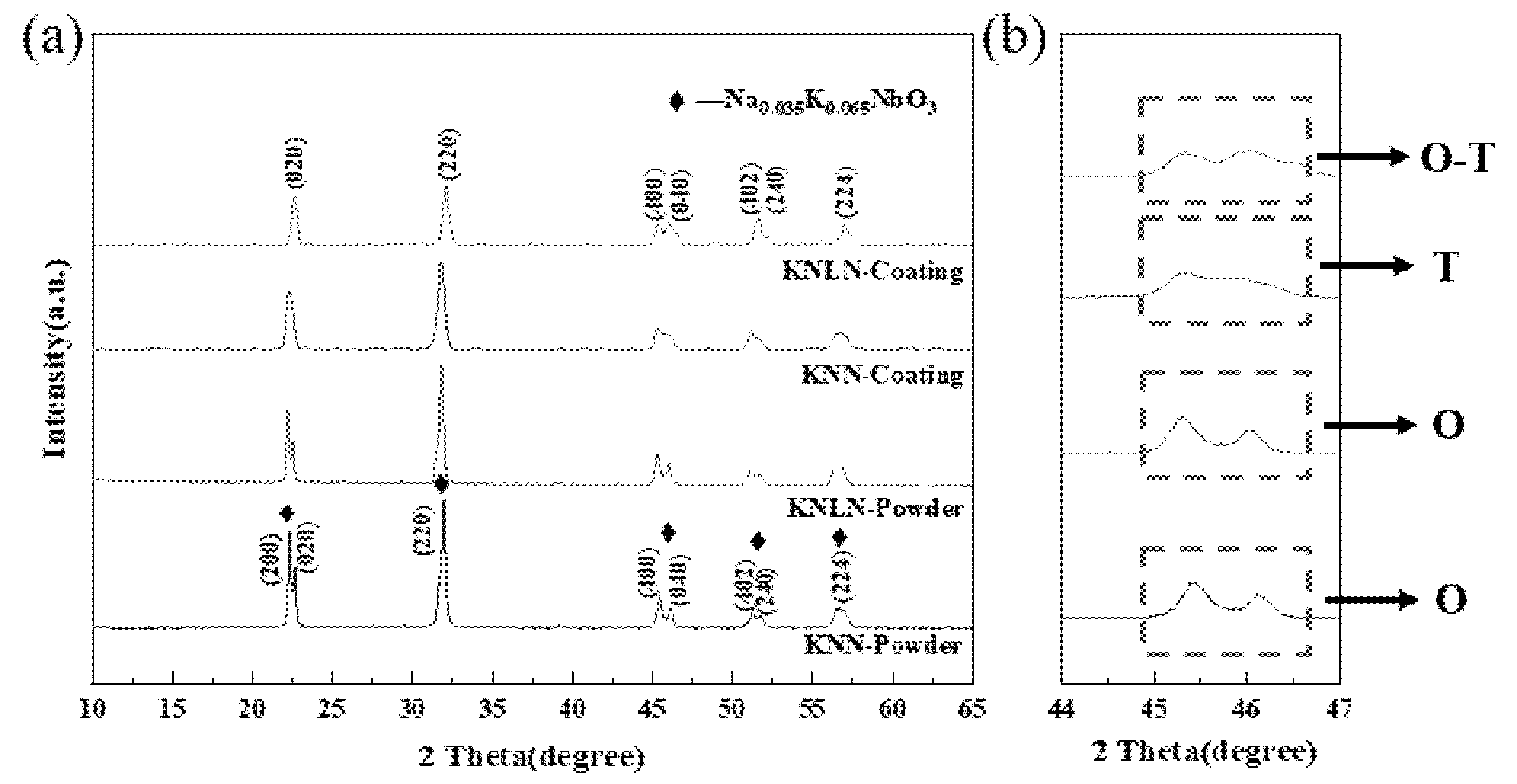
3.1. Phase Composition of Potassium Sodium Niobate (KNN) and KNLN ((K0.4675Na0.4675Li0.065) NbO3) Powders and Coatings

Figure 2 shows the XRD patterns of KNN and KNLN powders and coatings. It can be seen from Figure 2a that the characteristic peaks are all corresponding to Na0.035K0.065NbO3, the prepared KNN-based coatings are all consistent with the powders, and the peak intensity is weakened, indicating that the crystallinity is reduced. The decrease in crystallinity leads to a decrease in the dielectric constant and an increase in dielectric loss [14], but still maintains a single perovskite structure, and the KNLN coating does not find the second phase. In the process of supersonic plasma spraying, high temperature will lead to the volatilization of basic elements Na and K, leaving cation vacancies, and Li+ first occupies these vacancies, replacing A-site K+ or Na+ to form a new solid solution [15].
Figure 2b is an enlarged XRD image of 2θ = 44–47°. It can be seen that the diffraction peaks of pure KNN coating and KNLN coating are a little higher on the left than on the right, indicating that the powder is mainly orthogonal phase, while for the KNN coating, the two peaks tend to merge into one peak, which is still high on the left and low on the right. It is dominated by the orthogonal phase, containing a small amount of tetragonal phase, and the tetragonal degree c/a is 0.998. The two peaks of the KNLN coating tend to be parallel, the orthogonal phase and the tetragonal phase coexist, the tetragonal degree c/a is 1.012. It can be seen the KNLN coating has a larger tetragonality than the KNN coating, and the tetragonal structure component has a higher piezoelectric coefficient than the orthogonal structure component. This is because when the O-T phase coexists, more spontaneous polarization directions will be generated [16,17]. There are more spontaneous polarization directions in ceramics, which is conducive to domain rotation and greatly improves piezoelectric activity. Therefore, the coexistence of the orthogonal phase and the tetragonal phase gives the KNLN coating better dielectric and ferroelectric properties than the pure KNN coating.

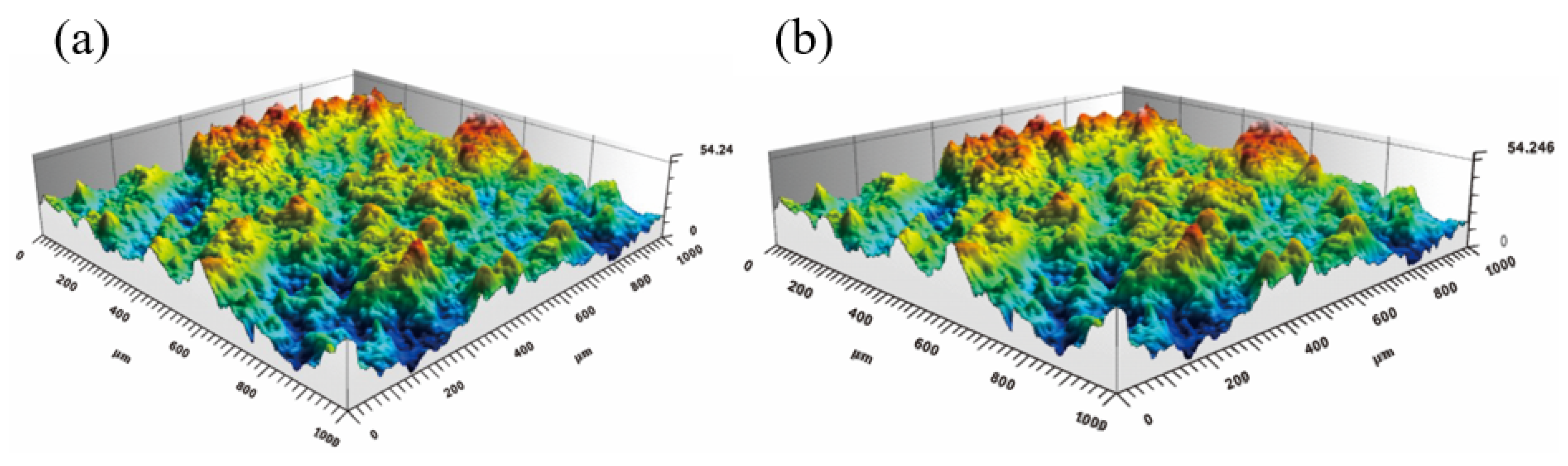
3.2. Three-Dimensional Morphology of KNN and KNLN Coatings

The three-dimensional morphology of the two coatings is shown in Figure 3. It can be intuitively observed that the surface undulations of the two coatings are small, the average line roughness of the KNN and the KNLN coating is Ra = 2.54 μm, Ra = 2.53 μm, respectively, and the mean square roughness is Sq = 8.31 μm, Sq = 6.92 μm, respectively. The literature points out that the roughness of the coating mainly depends on the particle size and melting degree of the powder [18,19,20]. It can be seen that the two powder particles form droplets during the high-temperature and high-speed spraying process and overlap and stack on the substrate at an ultra-fast speed and, as a result, a flat and dense coating is formed. The smaller the roughness, the more the powder has been fully melted by supersonic plasma spraying, and the perovskite structure is maintained or approached to the greatest extent, which makes it easier to enhance the perovskite phase strength of the coating in the subsequent heat-treatment process, and enhance its crystallinity for better electrical properties.

3.3. Cross-Sectional Morphology of KNN and KNLN Coatings

Figure 4 is the cross-sectional SEM and enlarged view of the KNN and KNLN coating. From Figure 4a,b, it can be seen that the coating thickness is about 100 μm, and the ceramic coating is between the substrate and the inlay, there are cracks between the coating and the substrate, but the combination of KNLN coating and substrate is significantly better than that of the pure KNN coating. Figure 4c,d is an enlarged view of the two ceramic coatings. It can be seen that there are no obvious holes and cracks in the two coatings, and the coating is denser. Compared with the small part of the unmelted particles in the pure KNN coating, the KNLN coating melts more completely; this is due to the jet temperature as high as tens of thousands of degrees Celsius of supersonic plasma spraying, which makes the powder melt better. Although the time is very short, the overall coating is denser at this power. There are cracks at the junction of the two coatings and the substrate. This is due to the mismatch of the thermal expansion coefficient between the ceramic coating and the substrate. A large amount of residual stress is generated in the structure, which leads to defects and even structural failure [21,22,23], as shown in Table 2, the heating and cooling during the heat treatment process will also produce significant internal stress on the structure, resulting in cracks in the joint.

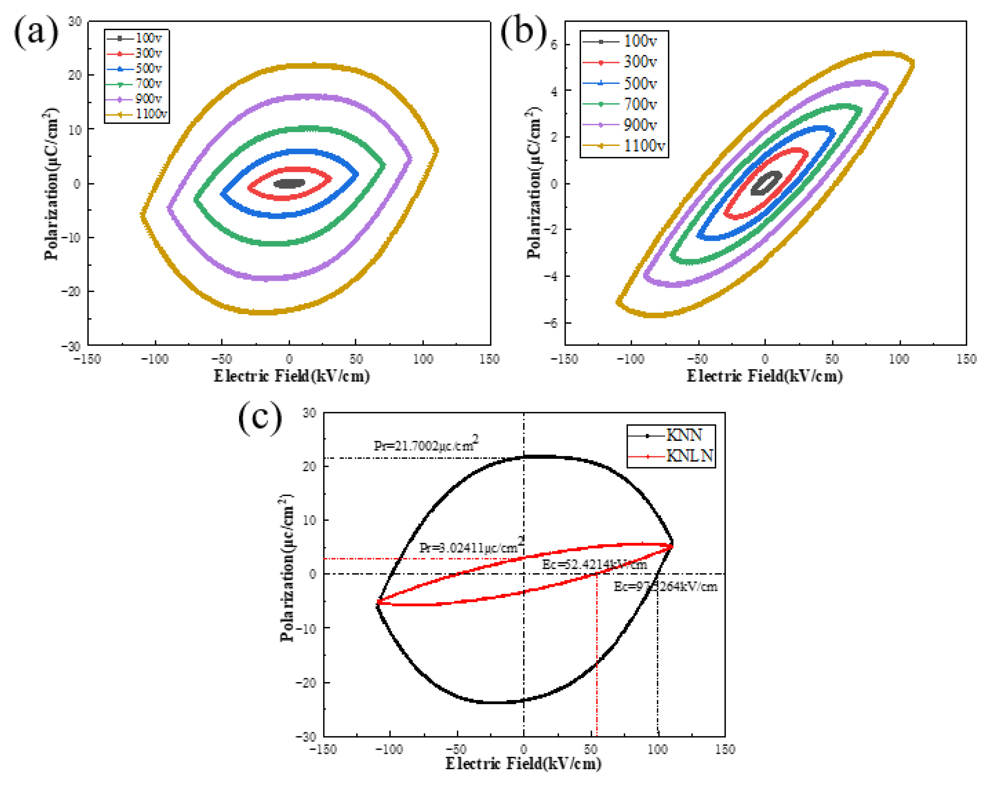
3.4. Ferroelectric Properties of KNN and KNLN Coatings

Figure 5a,b depicts the hysteresis loops of the KNN coating and KNLN coating at different polarization voltages. The obtained PE hysteresis loops clearly show the ferroelectric behavior of the prepared KNN-based coating. As the polarization voltage increases, the KNN coating becomes more full and flat, and the residual polarization value can reach 21.70 μC/cm2, but the coercive field strength is as high as 97.53 kV/cm, making it more difficult to polarize. The electric hysteresis loop of the KNLN coating becomes more slender and compressed. The residual polarization value is up to 3.02 μC/cm2, and the coercive field strength reaches 52.42 kV/cm. Although the residual polarization value of the KNLN coating is lower, its coercive field strength is relatively lower. It shows that the electric domain deflection of the ceramic coating under Li+ doping has a faster response to the external electric field, and the hysteresis is reduced.
Figure 5c is the hysteresis loop diagram of the KNN and KNLN coatings at a polarization voltage of 1100 V. The curve is closed, indicating that there is no large crack inside the sample; and from the area enclosed by the curve is the leakage current, it can be seen that there are leakage currents in both. The leakage current of the pure KNN coating is much greater than that of the KNLN coating. This is because the KNN coating has more cracks and unmelted particles than the KNLN coating, which can be confirmed by Figure 4. At the same time, during the spraying process, the temperature reaches tens of thousands of degrees Celsius, and the alkali metal ions Li+, Na+, K+ are easy to volatilize, resulting in the formation of oxygen vacancies inside the coating; the existence of oxygen vacancies leads to a larger leakage current, resulting in poor piezoelectric and ferroelectric properties of the KNN coating [24,25,26]. While the Li+-doped KNN coating is also volatilized severely at high temperatures, and the defects and pores caused by the volatilization of the alkali components may limit domain switching, the addition of Li not only compensates for the charging defects, but also improves the degree of densification of the thick film. As a result, domains become easier to switch, which leads to a reduction in EC [9]. This shows that the Li+ doped KNN coating has many domain walls, which is more conducive to the polarization of the coating, the domain deflection responds more quickly to the external electric field, and the domain wall movement has less resistance to the external electric field. Therefore, higher ferroelectric properties than with pure KNN coatings are obtained.

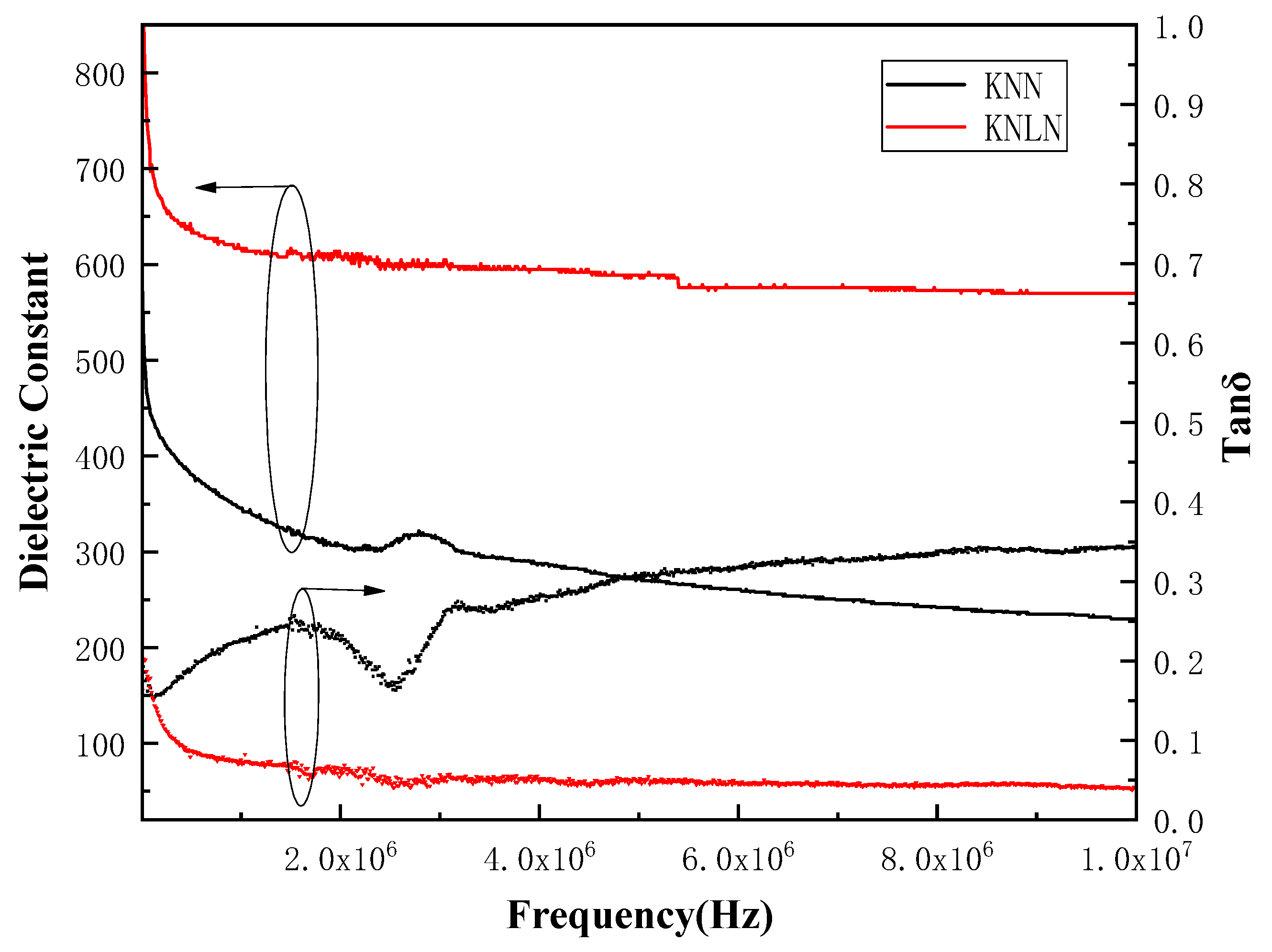
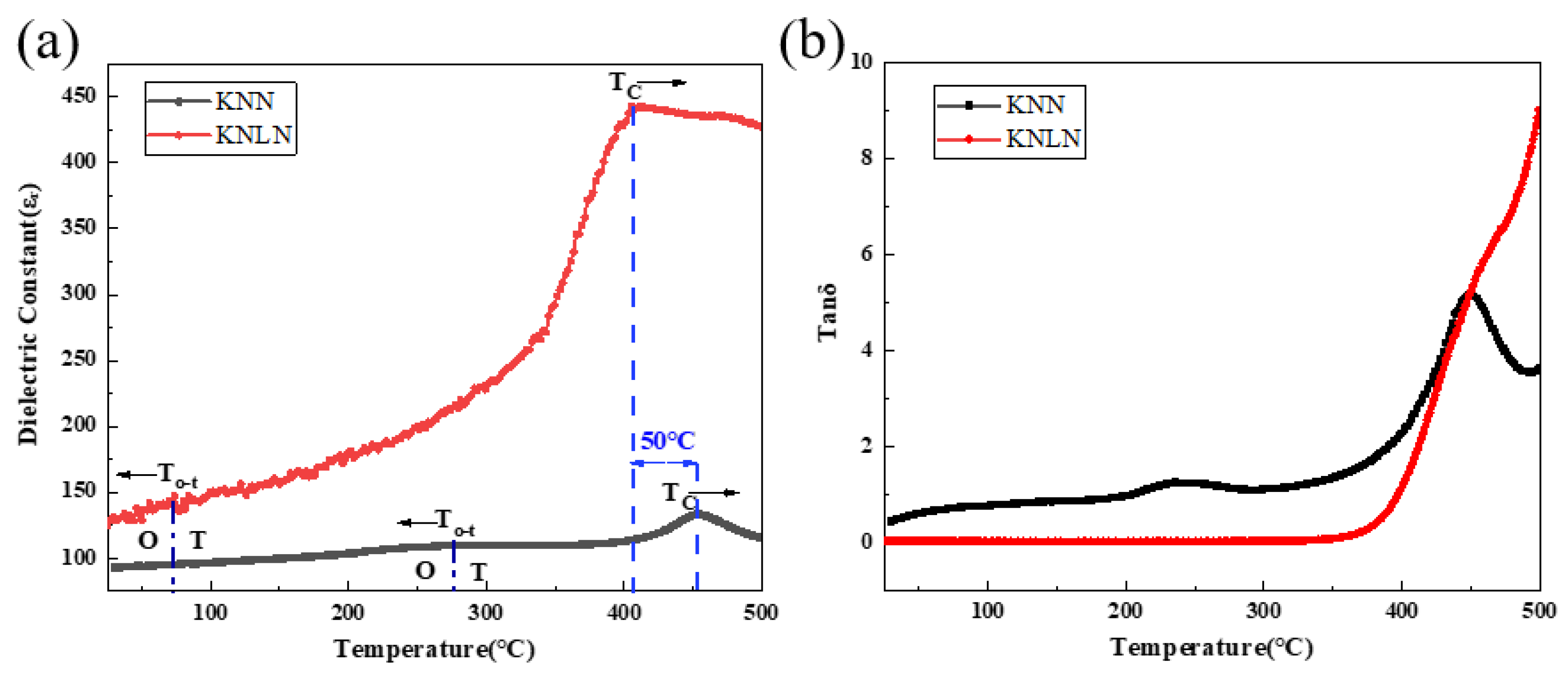
3.5. Dielectric Properties and Piezoelectric Properties of KNN and KNLN Coatings

Figure 6 describes the dielectric constant and dielectric loss of the KNN and KNLN coatings with frequency. It can be seen that the dielectric constants of the two coatings decrease with the increase in frequency until they are stable. The dielectric constant of the pure KNN coating is stable at about 250, and the dielectric loss value is between 0.15–0.35 while the dielectric constant of the KNLN coating reaches 600, which is significantly higher than that of the pure KNN coating. Its dielectric loss is stable at about 0.05, which is significantly lower than that of the pure KNN coating, indicating that the doping of Li+ can significantly improve its dielectric properties.
Relative permittivity is influenced by structural inhomogeneity like grain boundaries, oxygen vacancies, pores and cracks. Since the polycrystalline ceramic coatings are processed at extremely high temperatures, these defects are unavoidable. By understanding the character of these defects, the dielectric characteristics of KNN-based ceramics can be tailored. Besides that, Kui Yao [11], indicated that the thermal spraying with low plasma power often results in considerable unmelted particle population and thus porosity and physical defects, leading to high dielectric loss, which is consistent with the results in Figure 4. Therefore, air trapped in pores and cracks could affect the dielectric properties.
Figure 7 shows the temperature dependence of the dielectric constant and dielectric loss of KNN and KNLN piezoelectric ceramic coatings. The data are listed in Table 3, and it can be known that the KNN coating has a higher piezoelectric coefficient than the KNLN coating. The dielectric constant and dielectric loss were measured during heating at 1 kHz. As shown in Figure 7a, the dielectric constant of both increases first to the Curie temperature and then decreases with the increase of temperature, that is, the ferroelectric phase-paraelectric phase transition point. The Curie temperature of the KNLN coating is 405 °C, the dielectric constant reaches 445 pC/N. While the Curie temperature of the pure KNN coating is as high as 455 °C, which is significantly higher than that of the bulk material (420 °C), the dielectric constant is only 130 pC/N.
According to reports, K0.5Na0.5NbO3 ceramics have two phase transitions near 220 °C and 420 °C, corresponding to the orthogonal-tetragonal (To-t) and tetragonal-cubic (or Curie temperature Tc) phase transition temperatures, respectively [27]. Here, both the KNN and KNLN piezoelectric coatings have two dielectric peaks. The KNN piezoelectric coatings are identified around 280 °C and 455 °C respectively. These two temperature values are relatively close to the corresponding values reported in K0.5Na0.5NbO3. The Li+-doped KNN piezoelectric coating is recognized at around 75 °C and 405 °C. These two temperature values are very close to the corresponding values reported in K0.5Na0.5NbO3 ceramics, as shown in Figure 7a.
It can be seen that the To-t of the Li+ doped KNN piezoelectric coating significantly shifts to a lower temperature, while the Tc is about 50 °C lower than that of the pure KNN coating. According to relevant reports in the literature, the increase of Curie temperature can be attributed to the increase in tetragonality as the lithium content increases. In fact, for some perovskite solid solution ceramics, such as BiScO3-PbTiO3 and Pb(Mg1/3Nb2/3)O3-PbTiO3, the increase in tetragonality usually corresponds to the increase of the Curie temperature [28,29]. It can be confirmed from the XRD results in Figure 1 that the doping of Li+ increases the tetragonality of the KNN piezoelectric ceramics. It is inferred that the decrease in Curie temperature may be due to the volatilization of alkaline elements during the high-temperature spraying process, resulting in an imbalance of the element ratio.
From Figure 7b, it can be seen that the dielectric loss of both is relatively low before 200 °C, and increases slowly with the increase of temperature, and the dielectric loss of the Li+-doped KNN coating is significantly lower than that of pure KNN coating. The pure KNN coating is above 0.5. This is because the pure KNN coating has more cracks and unmelted particles than the KNLN coating, which makes the leakage current and dielectric loss larger.
It can be seen that the Li+-doped KNN coating has better electrical properties than the pure KNN coating. The dielectric constant and d33 is higher, the dielectric loss is lower, and the hysteresis loop is slender, that is, the leakage current is smaller. Why does the Li+-doped KNN coating have better electrical properties than the pure KNN coating? This is attributed to the fact that Li+ doped KNN coatings have a denser microstructure and a single perovskite phase structure, as well as a polycrystalline phase boundary where the orthogonal phase and the tetragonal phase coexist.

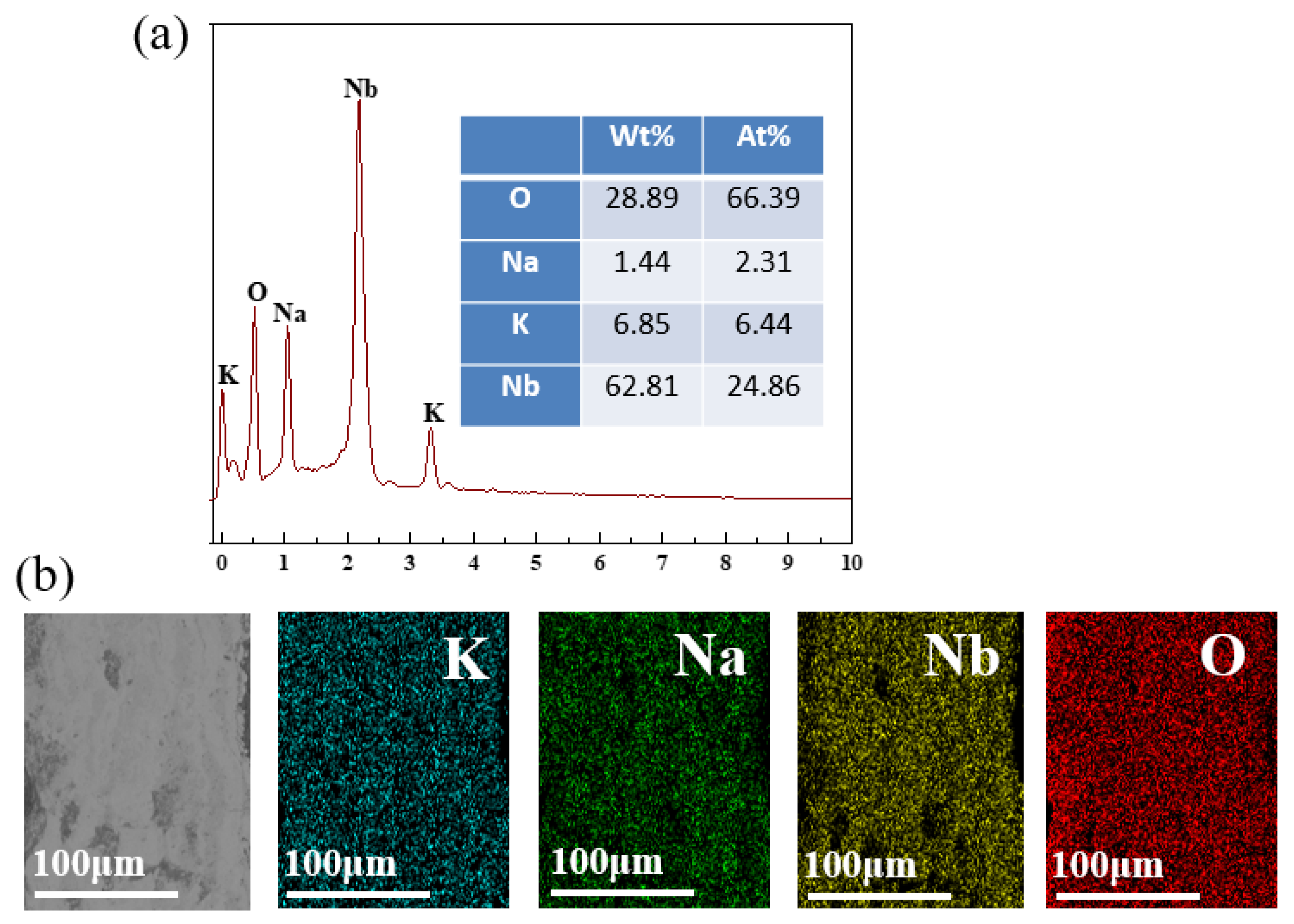
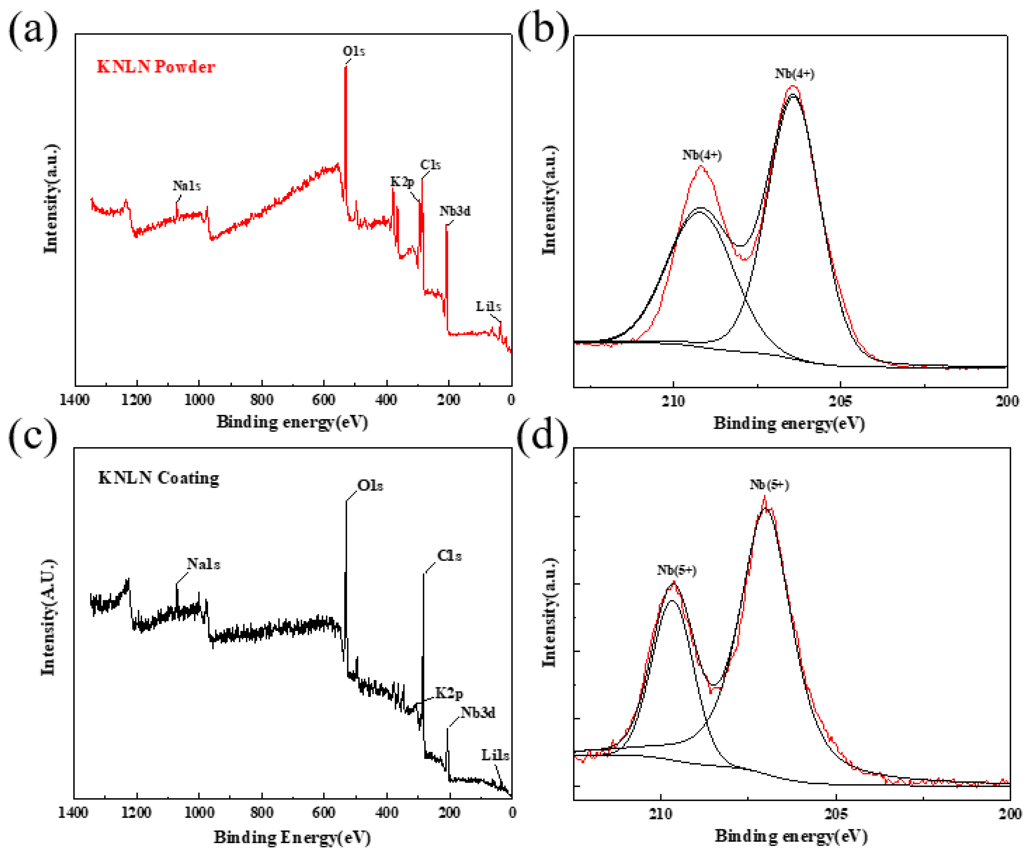
3.6. Energy Spectrum of KNN Coating and X-ray Photoelectron Spectroscopy (XPS) Analysis of Li-Doped KNN Powder and Coating

Figure 8 is the mapping of the KNN coating section. Figure 8a is the quantitative distribution of elements in the coating, and Figure 8b is the element distribution of the coating. It can be seen that the ceramic coating contains K, Na, Nb, and O. At the same time, the quantitative analysis of the elements shows that the weight percentages of Na and K are 1.44% and 6.85%, respectively. The burning loss of Na and K elements is serious, and the Na element loses more than the K element. This is because in the supersonic plasma spraying process, the temperature reaches tens of thousands of degrees Celsius, although the spraying time is short, the alkaline ion Na element is easier to volatilize than the K element, and the burning loss is serious during the high-temperature spraying process, which has a certain impact on the subsequent electrical performance, resulting in larger leakage current and dielectric loss, which is consistent with the previous results.
In order to further determine the phase composition of the coating, the sprayed sample was cut into a small sample of 25 mm × 20 mm × 5 mm for photoelectron spectroscopy (XPS). XPS was used to analyze the KNLN powders and coatings, which not only provided the chemical elements and structural features existing on the surface of the coating and the inside of the coating, but also reflect the bonding between the coating and the substrate, which is conducive to in-depth understanding of the deposition process of the KNLN coatings. Figure 9a,c show the XPS full spectrum of KNLN powder and coating. It can be seen from the figure that the coating contains Nb, Na, K, Li and O elements, which is consistent with the element composition in the spray powder The intensities of the peaks corresponding to the elements O and Nb are far greater than those of the elements Na, K and Li. This is related to the chemical composition of the spray powder, that is, KNLN powder is made by mixing and sintering Na2CO3, K2CO3, Li2CO3 and Nb2O5 in a certain proportion, and in order to supplement the alkaline metal ions that are volatile during the high temperature spraying process, 10% mol of Na and K elements are added. The reaction formula between the powder is:
0.27375Na2CO3 + 0.24375K2CO3 + 0.0325Li2CO3 + 0.5Nb2O5 = K0.4875Na0.5475Li0.065NbO3
The molecular formula is Na0.5475K0.4875Li0.065NbO3, in which the content of Na element is reduced from 3.13% (at) of the spray powder to 1.88% (at) of the coating, and the content of K element is reduced from 10.68% (at) of the spray powder to that of the coating 1.08% (at). The intensity of the spectral peak shown in Figure 9a,c is roughly consistent with the actual composition of the powder and coating elements. The peak intensities of Na, K and Li are slightly lower, and K loses more than Na. This may be because K is more volatile than Na. In the process of supersonic plasma spraying, the temperature is as high as tens of thousands of degrees Celsius, resulting in serious burning loss of volatile alkali metal ions.
Figure 9b,d are the XPS spectra of the Nb element in the powder and coating. According to literature reports, the Nb5+ oxidation state has a Nb 3d5/2 peak at 207.5 eV, and the Nb4+ oxidation state has Nb 3d5/2 at 206.2 eV. peak [30,31]. It can be seen that there are two peaks of Nb in the powder, the Nb 3d/3/2 peak with an electron binding energy of 206.4 eV and the Nb 3d5/2 peak at 209 eV, corresponding to the peak of Nb4+. The Nb element in the coating also has two peaks, namely the Nb 3d/5/2 peaks with electron binding energy of 207 eV and 209.75 eV, both of which correspond to Nb5+, containing a small amount of Nb4+.
Based on these results, it can be concluded that the coating prepared by supersonic plasma spraying has both oxygen vacancies and Nb4+ after heat treatment. This may be caused by the volatilization of alkali metals Li, Na, and K during the high-temperature spraying process [32,33]. It can also be concluded that the molten state from the powder to the coating is good and still maintains a single perovskite phase structure, but the volatilization of alkali metal elements has a greater impact on the electrical properties of the coating.

4. Conclusions

In this paper, pure potassium sodium niobate coating and the KNLN coating were successfully prepared by supersonic plasma spraying. The dielectric, piezoelectric and ferroelectric properties of the coatings were studied, The influence mechanism was explained from the perspective of phase composition and microstructure (cross-section). The main conclusions are as follows:
  • The prepared KNN and KNLN coatings have compact morphology and small surface roughness, but the KNN coating contains some unmelted particles, and there are micro cracks at the junction of the two coatings and the substrate, which are caused by the mismatch of the thermal expansion coefficient of the ceramic and the substrate. Both coatings are of a single perovskite structure. The pure KNN coating is an orthogonal phase structure, and the doping of Li+ successfully builds a polycrystalline phase boundary in which O–T phases coexist, which has higher dielectric, piezoelectric and ferroelectric properties.
  • With the increase of polarization voltage, the pure KNN coating is flatter and fuller, but the leakage current is large. The hysteresis loop of the KNLN coating is relatively slender and easy to polarize, and domain deflection responds faster to an external electric field. The resistance of the domain wall motion to the external electric field is small, therefore, the O–T phase coexistence structure has higher ferroelectric performance.
  • The dielectric constant of the KNLN coating is 375, which is much higher than 125 of the pure KNN coating, and the dielectric loss is stable at 0.01, which is lower than the 0.1–0.35 of the pure KNN coating. The d33 of KNN coating and KNLN coating are 8 and 14, respectively. Therefore, the O–T phase coexistence structure has a higher dielectric and piezoelectric properties.
  • Due to the high-temperature acceleration process in the supersonic plasma spraying process, the violent volatilization of the alkaline elements Li+, Na+ and K+ results in the existence of oxygen vacancies and part of Nb4+ in the coating, which will seriously affect the electrical properties of the coating.

Author Contributions

Conceptualization, Z.L.; methodology, D.H.; formal analysis, Y.S. and W.G.; data curation, Y.S.; writing—original draft preparation, Y.S.; writing—review and editing, Y.H.; visualization, W.G. and X.Z.; supervision, Z.X. and Z.L.; project administration, D.H.; funding acquisition, Z.X. All authors have read and agreed to the published version of the manuscript.

Funding

Financial support from General program of the National Natural Science Foundation of China (Grant No. 51775554) and General program of the National Natural Science Foundation of China (Grant No. 52005511).

Institutional Review Board Statement

Not applicable.

Informed Consent Statement

Not applicable.

Data Availability Statement

The data presented in this study are available on request from the corresponding author.

Conflicts of Interest

The authors declare that they have no known competing financial interest or personal relationships that could have appeared to influence the work reported in this paper.

References

  1. Malric, B.; Dallaire, S.; El-Assal, K. Crystal structure of plasma-sprayed PZT thick films. Mater. Lett. 1987, 5, 246–249. [Google Scholar] [CrossRef]
  2. Thielsch, R.; Haessler, W.; Brueckner, W. Electrical properties and mechanical stress of thick plasma-sprayed Pb (Zr0. 58Ti0. 42) O3 coatings. Phys. Status Solidi (A) 1996, 156, 199–207. [Google Scholar] [CrossRef]
  3. Sherrit, S.; Savin, C.R.; Wiederick, H.D.; Mukherjee, B.K.; Prasad, S.E. Plasma-Sprayed lead zirconate titanate-glass composites. J. Am. Ceram. Soc. 1994, 77, 1973–1975. [Google Scholar] [CrossRef]
  4. Li, G.; Gu, L.; Wang, H.; Xing, Z.; Zhu, L. Microstructures and dielectric properties of PZT coatings prepared by supersonic plasma spraying. J. Therm. Spray Technol. 2014, 23, 525–529. [Google Scholar] [CrossRef]
  5. Liu, Z.; Xing, Z.; Wang, H.; Xue, Z.; Chen, S.; Jin, G.; Cui, X. Effect of ZnO on the microstructure and dielectric properties of BaTiO3 ceramic coatings prepared by plasma spraying. J. Alloys Compd. 2017, 727, 696–705. [Google Scholar] [CrossRef]
  6. Xing, Z.; Wang, H.; Zhu, L.; Zhou, X.; Huang, Y. Properties of the BaTiO3 coating prepared by supersonic plasma spraying. J. Alloys Compd. 2014, 582, 246–252. [Google Scholar] [CrossRef]
  7. Sen, C.; Alkan, B.; Akin, I.; Yucel, O.; Sahin, F.C.; Goller, G. Microstructure and ferroelectric properties of spark plasma sintered Li substituted K0. 5Na0. 5NbO3 ceramics. J. Ceram. Soc. Jpn. 2011, 119, 355–361. [Google Scholar] [CrossRef] [Green Version]
  8. Chin Goh, P.; Yao, K.; Chen, Z. Lithium diffusion in (Li, K, Na) NbO3 piezoeletric thin films and the resulting approach for enhanced performance properties. Appl. Phys. Lett. 2011, 99, 092902. [Google Scholar] [CrossRef]
  9. Fu, F.; Shen, B.; Zhai, J.; Xu, Z.; Yao, X. Electrical properties of Li doped sodium potassium niobate thick films prepared by a tape casting process. J. Alloys Compd. 2011, 509, 7130–7133. [Google Scholar] [CrossRef]
  10. Shen, Z.Y.; Li, Y.M.; Jiang, L.; Li, R.R.; Wang, Z.M.; Hong, Y.; Liao, R.H. Phase transition and electrical properties of LiNbO3-modified K0.49Na0.51NbO3 lead-free piezoceramics. J. Mater. Sci. Mater. Electron. 2011, 22, 1071–1075. [Google Scholar] [CrossRef]
  11. Chen, S.; Tan CK, I.; Yao, K. Potassium–Sodium Niobate-Based Lead-Free Piezoelectric Ceramic Coatings by Thermal Spray Process. J. Am. Ceram. Soc. 2016, 99, 3293–3299. [Google Scholar] [CrossRef]
  12. Guo, K.; Chen, S.; Tan, C.K.I.; Sharifzadeh Mirshekarloo, M.; Yao, K.; Tay, F.E.H. Bismuth sodium titanate lead-free piezoelectric coatings by thermal spray process. J. Am. Ceram. Soc. 2017, 100, 3385–3392. [Google Scholar] [CrossRef]
  13. Guo, K.; Mirshekarloo, M.S.; Lin, M.; Yao, K.; Chen, S.; Tay, F.E.H. Microstructure and piezoelectric properties of thermal sprayed Bi0. 5 (Na0. 70K0. 20Li0. 10) 0.5 TiO3 ceramic coatings. Ceram. Int. 2019, 45, 3570–3573. [Google Scholar] [CrossRef]
  14. Wang, L.; Yao, K.; Ren, W. Piezoelectric K0.5Na0.5NbO3 thick films derived from polyvinylpyrrolidone-modified chemical solution deposition. Appl. Phys. Lett. 2008, 93, 092903. [Google Scholar] [CrossRef]
  15. Rubio-Marcos, F.; Ochoa, P.; Fernandez, J.F. Sintering and properties of lead-free (K,Na,Li)(Nb,Ta,Sb)O 3 ceramics. J. Eur. Ceram. Soc. 2007, 27, 4125–4129. [Google Scholar] [CrossRef]
  16. Higashide, K.; Kakimoto, K.; Ohsato, H. Temperature dependence on the piezoelectric property of (1− x)(Na0. 5K0. 5) NbO3–xLiNbO3 ceramics. J. Eur. Ceram. Soc. 2007, 27, 4107–4110. [Google Scholar] [CrossRef]
  17. Rubio-Marcos, F.; Marchet, P.; Romero, J.J.; Fernández, J.F. Structural, microstructural and electrical properties evolution of (K, Na, Li)(Nb, Ta, Sb) O3 lead-free piezoceramics through NiO doping. J. Eur. Ceram. Soc. 2011, 31, 2309–2317. [Google Scholar] [CrossRef]
  18. Baig, M.N.; Khalid, F.A. Deposition and characterization of plasma sprayed Ni-5A1/magnesia stabilized zirconia based functionally graded thermal barrier coating. In Proceedings of the IOP Conference Series: Materials Science and Engineering, Islamabad, Pakistan, 23–27 September 2013; Volume 60, p. 012053. [Google Scholar]
  19. Song, D.; Wang, R.; Liu, W.; He, X. Microstructure and mechanical properties of PbSn alloys deposited on carbon fiber reinforced epoxy composites. J. Alloys Compd. 2010, 505, 348–351. [Google Scholar] [CrossRef]
  20. Zhen-yu, Z.; Qiu-yang, Z.; Cong, D.; Ju-yu, Y.; Guang-jian, P.; Zhong-yu, P. Research on the promotion mechanism of surface burnishing process by two-dimensional ultrasonic vibration. J. Mater. Res. Technol. 2021, 13, 1068–1082. [Google Scholar] [CrossRef]
  21. Izyumskaya, N.; Alivov, Y.I.; Cho, S.J.; Morkoç, H.; Lee, H.; Kang, Y.S. Processing, structure, properties, and applications of PZT thin films. Crit. Rev. Solid State Mater. Sci. 2007, 32, 111–202. [Google Scholar] [CrossRef]
  22. Hsueh, C.H.; Luttrell, C.R.; Cui, T. Thermal stress analyses of multilayered films on substrates and cantilever beams for micro sensors and actuators. J. Micromech. Microeng. 2006, 16, 2509. [Google Scholar] [CrossRef]
  23. Zhou, Z.; Zheng, Q.; Ding, C.; Yan, J.; Piao, Z. Effect of surface burnishing process with different strain paths on the copper microstructure. J. Manuf. Processes 2021, 71, 653–668. [Google Scholar] [CrossRef]
  24. Safari, A.; Abazari, M. Lead-free piezoelectric ceramics and thin films. IEEE Trans. Ultrason. Ferroelectr. Freq. Control 2010, 57, 2165–2176. [Google Scholar] [CrossRef]
  25. Nguyen, M.D.; Dekkers, M.; Houwman, E.P.; Vu, H.T.; Vu, H.N.; Rijnders, G. Lead-free (K0. 5Na0. 5) NbO3 thin films by pulsed laser deposition driving MEMS-based piezoelectric cantilevers. Mater. Lett. 2016, 164, 413–416. [Google Scholar] [CrossRef]
  26. Zhu, W.; Akkopru-Akgun, B.; Trolier-McKinstry, S. Highly accelerated lifetime testing of potassium sodium niobate thin films. Appl. Phys. Lett. 2017, 111, 212903. [Google Scholar] [CrossRef]
  27. Egerton, L.; Dillon, D.M. Piezoelectric and dielectric properties of ceramics in the system potassium—Sodium niobate. J. Am. Ceram. Soc. 1959, 42, 438–442. [Google Scholar] [CrossRef]
  28. Winotai, P.; Udomkan, N.; Meejoo, S. Piezoelectric properties of Fe2O3-doped (1− x) BiScO3–xPbTiO3 ceramics. Sens. Actuators A Phys. 2005, 122, 257–263. [Google Scholar] [CrossRef]
  29. Choi, S.W.; Shrout, T.R.; Jang, S.J.; Bhalla, A.S. Morphotropic phase boundary in Pb (Mg13Nb23) O3-PbTiO3 system. Mater. Lett. 1989, 8, 253–255. [Google Scholar] [CrossRef]
  30. Moulder, J.F. Handbook of X-ray photoelectron spectroscopy. Phys. Electron. 1995, 88, 230–232. [Google Scholar]
  31. Atuchin, V.V.; Kalabin, I.E.; Kesler, V.G.; Pervukhina, N.V. Nb 3d and O 1s core levels and chemical bonding in niobates. J. Electron Spectrosc. Relat. Phenom. 2005, 142, 129–134. [Google Scholar] [CrossRef]
  32. Popovič, A.; Bencze, L.; Koruza, J.; Malič, B. Vapour pressure and mixing thermodynamic properties of the KNbO 3–NaNbO 3 system. RSC Adv. 2015, 5, 76249–76256. [Google Scholar] [CrossRef]
  33. Hreščak, J.; Dražić, G.; Deluca, M.; Arčon, I.; Kodre, A.; Dapiaggi, M.; Rojac, T.; Malič, B.; Bencan, A. Donor doping of K0. 5Na0. 5NbO3 ceramics with strontium and its implications to grain size, phase composition and crystal structure. J. Eur. Ceram. Soc. 2017, 37, 2073–2082. [Google Scholar] [CrossRef] [Green Version]
Figure 1. (a) Morphology of KNLN powders and (b) Size distribution of KNLN powders.
Actuators 11 00039 g001
Figure 2. (a) X-ray diffraction (XRD) patterns of the KNN and KNLN powders and coatings; (b) enlarged XRD patterns in the range of 2θ from 44° to 47°.
Actuators 11 00039 g002
Figure 3. Three-dimensional morphology analysis of the coating surface (a) KNN (b) KNLN coating.
Actuators 11 00039 g003
Figure 4. Cross-sectional images of the (a) KNN coating, (b) KNLN coating. and cross-section enlarged view of the (c) KNN coating, (d) KNLN coating.
Actuators 11 00039 g004
Figure 5. Polarization–electric field hysteresis loops of the (a) KNN and (b) KNLN coatings under different polarization voltages and (c) 1100 v polarization voltage.
Actuators 11 00039 g005
Figure 6. Plots of dielectric constant and loss versus frequency for KNN and KNLN coatings.
Actuators 11 00039 g006
Figure 7. Dielectric temperature spectra of KNN and KNLN coatings. (1 KHz). (a) Dielectric constant and (b) Dielectric loss.
Actuators 11 00039 g007
Figure 8. Energy-dispersive X-ray spectroscopy (EDS) energy spectrum of pure KNN coating. (a) Elemental quantitative analysis and (b) Elemental distribution of coating section.
Actuators 11 00039 g008
Figure 9. X-ray photoelectron spectroscopy (XPS) spectra of KNLN powders and coatings: (a) full spectrum of KNLN powder, (b) Nb element spectrum of KNLN powder, (c) full spectrum of KNLN coating, (d) Nb element spectrum of KNLN coating.
Actuators 11 00039 g009
Table 1. Plasma spraying processing parameters for the potassium sodium niobate (KNN) and KNLN ((K0.4675Na0.4675Li0.065) NbO3) coatings.
Parameter (Unit)Value
Spraying current (A420
Spraying voltage (V)100
Spraying distance (mm)100
Primary gas Ar (m3h−1)7.2
Secondary gas H2 (m3h−1)0.48
Powder feeding rate (g min−1)20
Table 2. Thermal expansion coefficient comparison table [15,16,17].
MaterialCoefficient of Thermal Expansion (10−6/°C)Young’s Modulus (GPa)
KNN866
Ag/Pd15145
YSZ1038
NiCrAlY15137
Steel17200
Table 3. Piezoelectric coefficient of KNN coating and KNLN coating.
Materiald33/pC/NTo-t/°CTc/°C
KNN8280455
KNLN1575405
Publisher’s Note: MDPI stays neutral with regard to jurisdictional claims in published maps and institutional affiliations.

