Abstract
In order to investigate the mechanism of interaction between a vertical rotary tiller and the soil to obtain the best structural and operational parameters of the tool, improve the operational quality of the rotary tiller, achieve the effect of soil breaking and leveling to meet the agronomic requirements of tillage, a series of simulation tests was conducted through the design of 3D models of rotary tillers with different structural forms and the building of discrete element models of the action between the rotary tiller and the soil. The virtual simulation of different operating parameters and structural parameters of vertical rotary tiller was carried out by EDEM, and the effects of operating parameters, tool bending angle, and cutter installation number on the operating effect were analyzed. The parameter combination with the best operating effect was obtained through orthogonal test analysis and verified by soil trough test. A soil tank test showed that, with the optimal combination of operating and structural parameters, the average soil breaking rate of the vertical rotary tiller was 81.3%, which meets the agronomic requirements of tillage operation, and the actual power consumption was 6% higher than the simulation value, which was sufficiently close to verify the validity of the simulation. This study can lay a foundation for optimization research on the vertical miniature rotary tiller.
1. Introduction
Compared with traditional horizontal rotary tillage, vertical rotary tillage has the advantages of possessing strong soil-breaking ability, greater depth of rotation, faster operation speed, etc. As an important part of the rotary tiller, the rotary cutter can achieve the cutting of large pieces of soil by rotating and cutting the soil, while the spatial layout of the rotary cutter, tool structure parameters, and operating parameters directly affect the working quality and power loss of the rotary tiller [,,,]. Existing research on the structure and working parameters of vertical rotating tillers is limited, but some experts and scholars are working in this area. Among them, Zhang et al. [] conducted a kinematic analysis of a vertical rotating tiller to find a tool installation equipartition angle that could reduce the force of the whole machine. Liu et al. [] analyzed the bending angle of the tool and proved that the bending angle of the vertical rotary tiller effectively avoided the phenomenon of “soil resistance” and reduced operating power consumption by optimizing the arrangement and installation mode of the toolset. However, most of these works involve theoretical research and the ideas have not been tested. If the cultivation process can be simulated and the change in tools and soil can be analyzed through software simulation, research and development time will be shortened and research costs will be saved while optimizing tools and reducing energy consumption.
In recent years, numerous scholars have studied the interactions between soil and operating implements using discrete element simulation modeling, with studies conducted on a variety of operating implements such as deep loosening shovels [], push shovels [,], pendulum shovels [], furrow openers [], soil shovels [,], and rototillers []. The simulation results have shown that these models can simulate the tillage process and soil behavior well, and the simulation results agree well with experimental results. Discrete element models for the straight shear test, penetration test, and shovel test were developed by Ucgul et al. [,], and the results show that discrete element is an effective method by which to study soil–machine interactions.
Although there are numerous international researchers working on the soil-cutting process of the rotary tillage cutter, their work mainly focuses on certain parts of the force on the machine or blade. Marenya [], Salokhe [], and others have studied the traction force in a working rotary tiller. Iwasaki [] and others attempted to divide the rotary tiller into two parts, a curved blade and a straight blade, and analyzed the resistance of both blades. Asl and Singhl [] established dynamic and static soil-cutting resistance equations for the rotary tiller and analyzed the energy consumption associated with soil-cutting with the help of computers and numerical methods. Tang et al. [] carried out discrete element simulation analysis on the rotary tillage process of a single vertical rotary tillage blade and optimized the blade structure, but did not consider the interaction between the blades in the whole rotary tillage blade group. Therefore, at this stage, there is still a lack of research on the tillage process of a vertical rototiller group. Therefore, it is necessary to further study this tool and the soil changes that occur in the tillage process when using a vertical rotary tiller system.
In this study, the vertical rototiller system was simplified, a rototiller–soil model was established, and the optimal combination of tool structure and operating parameters was obtained using discrete element simulation test analyses with the power consumption and soil breaking effect as the test indexes, and results were then verified by soil tank testing.
2. Materials and Methods
2.1. Design of Vertical Rotary Tiller
2.1.1. Overall Structure Design
A vertical rotary tiller consists of a central gear box, sprocket box, vertical rotary tiller tool, telescopic cylinder, obstacle avoidance contact, travel switch, and three-point suspension structure, as shown in Figure 1. The vertical rotary tiller is connected to the main body of a vehicle with three-point suspension. The transmission is driven by the rotation of the hydraulic motor in the hydraulic system gear box. Under the motor rotation, the gear box drives the rotation of each fixed cutter. Each fixed cutter passes through a pair of sprockets to drive the rotation of two movable cutters so as to achieve vertical rotary tillage tool rotation. The entire machine’s operating width can be adjusted by the movement of the two movable cutters via a pair of cylinders. This enables adjustment of the width and the operation of automatic obstacle avoidance. When the outer corner of the tool touches an obstacle at both ends, a button behind the travel switch returns to its normal state. The circuit of the travel switch and the valve are directly connected in series and the travel switch is normally open, so the circuit is on, the hydraulic system responds, and the cylinder contracts to achieve automatic obstacle avoidance.
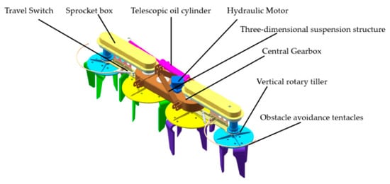
Figure 1.
Vertical rotary tiller structure diagram.
2.1.2. Rotary Tiller Design
As a key component of the vertical tiller, the operating effect of the rotary cutter will directly affect the operating quality and power consumption of the tiller. At the same time, the design of the rotary cutter assembly needs to consider the width of the cutter group, the width of the interlocking rotary cutters, and the spatial structure of the rotary cutter. The overall structure of a rotary tiller is shown in Figure 2.
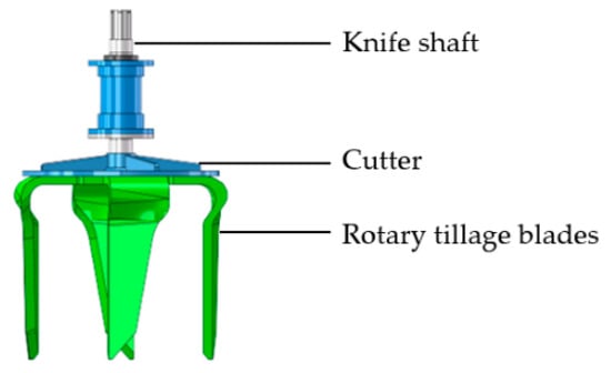
Figure 2.
Vertical rotary tiller.
A vertical rotary tillage knife includes four design elements, namely, blade inclination, tool bending angle, blade bending angle, and tip rounding angle. Among them, the blade inclination can change the mechanism of the soil cutting and the soil and tool contact outflow position; the tool bending angle can affect the rotating work of the rotating knife and the soil crushing and throwing effect; the blade bending angle can increase the effective working area of the rotating knife to avoid the back of the knife and other nonworking parts contacting the untilled soil, resulting in unnecessary wear and power loss; and the tip angle can effectively reduce the soil reaction force when the rotary tillage knife enters the soil. These different parameters of the vertical rototiller are presented in Figure 3. The present study was primarily focused on the analysis of the soil-breaking effect, so only the bending angle of the knife is discussed below.

Figure 3.
Vertical rotary tiller structure parameters: , blade inclination;, tool-bending angle; , knife edge outward bending angle;, blade tip rounding.
2.2. Discrete Element Simulation Modeling
2.2.1. Discrete Element Modeling of Soils
Related studies have shown that the computational accuracy of a simulation decreases geometrically when the radius of the soil particle model increases; therefore, when building the soil particle model, considering the computer processing efficiency and simulation effect [,,,], we chose an 8 mm radius sphere as the soil particle model. The soil particle model used in the simulation is shown in Figure 4.
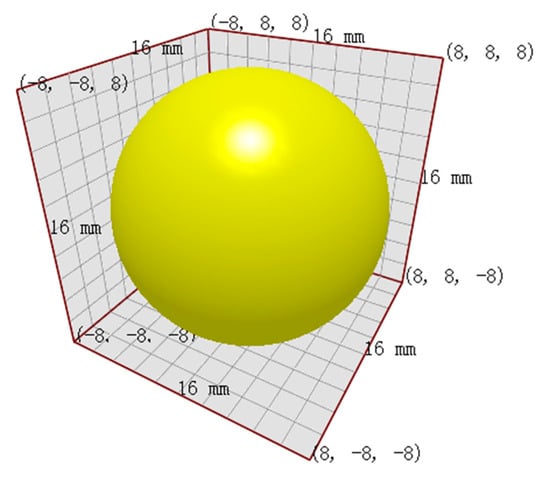
Figure 4.
Soil particle model.
The physical and mechanical parameters of soil are different at different depths, and in order to simulate actual soil conditions more practically, a soil model should be separated into three layers, i.e., the tillage layer, the plow bottom layer, and the heart soil layer. Of these, the thickness of the tillage layer is about 12 cm, the thickness of the plow bottom layer is about 6 cm, and the thickness of the heart soil layer is about 15 cm. The vertical rototiller designed in this study had an operating width of 1.7 m, so the size of the soil trough was set at 180 × 200 × 33 cm, as shown in Figure 5.
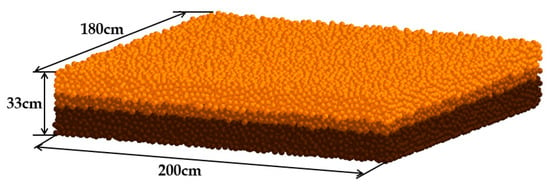
Figure 5.
Soil structure model.
2.2.2. Discrete Element Model for Vertical Rotary Tiller
In order to truly simulate the operation of a vertical rototiller and improve the simulation efficiency, we established a vertical rototiller model by equivalently simplifying the structure of the unit, as shown in Figure 6. The key parameters of the unit were optimized for simulation, and the simplified model was imported into EDEM (DEM-Solutions, Edinburgh, UK, 2021) for simulation tests.

Figure 6.
Vertical rotary cutter set model.
2.3. Contact Model and Parameter Setting
2.3.1. Contact Model
The EDEM software has many built-in contact models that can accurately simulate the cohesive soil properties of the Hunan region in China, and we used the Hertz–Mindlin with Bonding model [,,,,]. Based on the Hertz–Mindlin with JKR model, bonding bonds are added between the particles to form a whole that can withstand tangential and normal displacements (the particle bonding model is shown in Figure 7) and, when subjected to the maximum shear stress (i.e., fracture bonding point), the bonding bonds break, causing the overall fragmentation. The bonding model was used to simulate the soil structure, and the bonding fracture change law was analyzed to study the soil-breaking effect of the agricultural machinery.
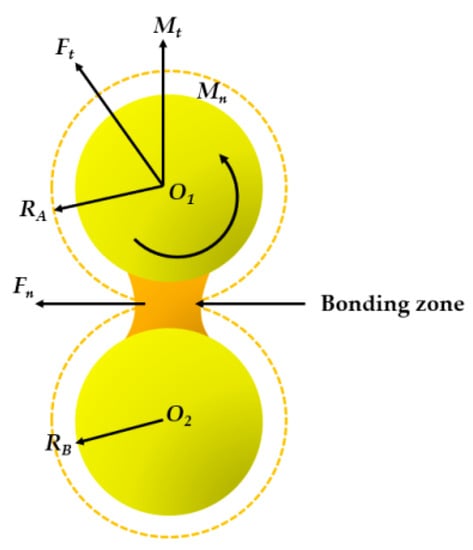
Figure 7.
Particle bonding model.
In the picture, O1 and O2 are the centers of the circles of the soil model; RA is the bond radius and RB is the particle radius; Fn is normal contact force, N; Ft is tangential contact force, N; Mn is normal moment, N·m; and Mt is tangential moment, N·m.
The calculation equation is as follows:
—tangential contact force, —normal contact force, N; —particle tangential moment, —particle normal moment, N·m; contact area, ; moment of inertia, —bonding bond radius, m.
2.3.2. Parameter Setting
The discrete element simulation parameters consisted of material parameters (density, Poisson’s ratio, shear modulus of soil particles, and rotary tillage knife material), material contact parameters (recovery coefficient, static friction coefficient, and rolling friction coefficient between soil particles and between soil particles and rotary tillage knife), and contact model parameters (five parameters of Hertz–Mindlin with Bonding particle contact model).
The soil used in this study was from the experimental field of Hunan Agricultural University. Through parametric tests and a literature review [,,,], the parameters involved in the simulation tests were determined as shown in Table 1, Table 2 and Table 3.

Table 1.
Material parameters.

Table 2.
Material contact parameters.

Table 3.
Contact model parameters.
2.4. Discrete Element Simulation
A fixed time step of 3 × 10⁻⁵ was set and the grid size was set at 2.5 times the minimum particle size for discrete element simulation analysis. The simulation process is illustrated in Figure 8.
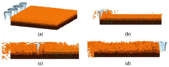
Figure 8.
Simulation process diagram (a) 4.0 s; (b) 4.3 s; (c) 5.1 s; (d) 5.6 s.
In the vertical rototilling operation process (Figure 9), the soil particles are displaced by the action of the rototiller. The soil is stirred and broken at the same time and is also thrown upward and outward. With the rototiller constantly cutting, turning, and throwing the soil, the soil failure range becomes larger. The surface of the soil remains flat after rototilling.
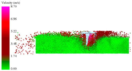
Figure 9.
Local enlargement of simulation test.
2.5. Simulation Test Index Acquisition
2.5.1. Crushed Soil Effect Collection Method
After the soil particles settle naturally, bonding bonds are generated between the particles to bond adjacent particles so that the whole soil model is bonded into a whole. The soil-breaking effect of the rotary tillage knife under different parameters is reflected by observing the breaking of bonding bonds during the rotary tillage knife operation. Soil-crushing data were collected by the EDEM post-processing module, and the statistics of bond generation and the number of broken bonds are shown in Figure 8.
As can be seen from Figure 10, the simulation started running at 0 s, the particle factory generated particle models, the particles were deposited naturally from 0 to 3 s, bonding bonds were generated between particles at 3.3 s, the bonding bonds between particles gradually stabilized from 3.3 s to 4 s, and the particles were slowly deposited to a stable state. At 4 s, the rotary tillage knife started to move and make contact with soil particles, and the bonds between particles subjected to the rotary tillage operation started to break and tended towards a stable decline over time.
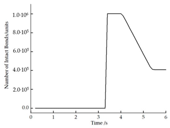
Figure 10.
Changes in the number of soil connection bonding bonds during the operation.
The number of bonded bond connections showed a steady decreasing trend and the change pattern did not change with time. Therefore, to improve the calculation efficiency, the number of bond reductions within 1 m of rotary cutter advance was used as the index of the rotary cutter operation effect.
2.5.2. Power Consumption Collection Method
Power consumption is the power consumption of the unit. In this paper, the sum of the power consumption of four tools was taken as the power consumption of the whole machine, and the total power consumption was obtained by collecting the torque and rotational speed of each tool. In the simulation environment of the EDEM 2021 software, the rotational speed of the tool was set as a constant value that did not fluctuate with changes in tillage resistance. Therefore, it was only necessary to collect the torque of the simulated tool and then calculate the power consumption of each tool according to the rotational speed, and then find the total power consumption of the entire machine.
The vertical rotating tool model was moved forward along the y axis, and a smooth operation period was selected to collect the torque value of the tool. The length of the period selected in this study was 1 s. The torque was collected by the post-processing module to generate the torque versus time variation of the rotating tool, as shown in Figure 11, and the average value of the torque of each tool was the rotating torque of each tool.
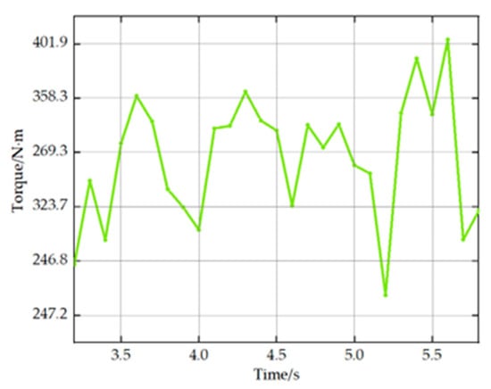
Figure 11.
Rotary tiller operating torque versus time variation.
After the torque collection was completed, the power of each rotary cutter was calculated using Equation (3) and these values were summed to obtain the total power consumption of the unit.
T—the tool torque (N·m); n—the tool rotation speed (r·min−1).
2.6. Soil Trough Test
2.6.1. Soil Tank Test Conditions
In the Hunan Agricultural University Agricultural Machinery Training Center for prototype soil tank experiments, the vertical rotary tillage equipment was installed on the TCC electric 4 WD soil tank test vehicle of Hunan Agricultural University Agricultural Machinery Training Center. The soil trough length was 30 m and the width was 2.95 m. The vehicle is driven by a frequency conversion motor with an input voltage of 380 V and a rated power of 30 kW and can achieve stepless speed regulation within the speed range 0.3~10 km/h; the power output frequency conversion motor is a 30 kW Taiwan Fuda frequency conversion motor with a base frequency of 50 Hz and stepless speed regulation by an ORS 2000S 30 kW frequency converter.
The test soil used was taken from the test field of Hunan Agricultural University. The soil was compacted before the test, and its density was measured to be 2670 kg/m3 with an average moisture content of 26.25%. The average firmness of the soil from 0 to 40 cm was measured to be 0.65 MPa using an SC900 soil firmness tester, and the soil properties were basically the same as the soil used in the simulation test.
2.6.2. Soil Tank Test Plan
The test equipment included a Reynolds CHPM hydraulic tester, TM-85 soil density meter, TJSD-750-IV soil compaction meter, WKT-M1 soil moisture meter, WT-CF series high-precision electronic scale, steel frame tape measure, and meter ruler.
Based on the parameter combinations derived from the simulation test analysis, soil tank tests were conducted to verify each set of parameter combinations five times, and the average value was obtained and compared with the simulation test results for analysis. The process of soil tank testing is shown in Figure 12.
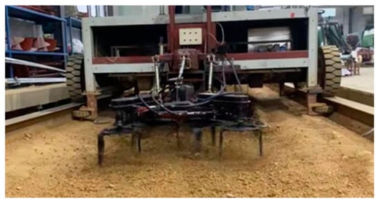
Figure 12.
Experimental test process diagram.
Test index test method:
- Plowing depth
The distance to the bottom of the furrow on the surface of the unplowed land was measured as the plowing depth using a plowing depth ruler. The length of the test area was 40 m, and each time one stroke was completed, the soil was re-compacted and then plowed again. Five strokes were checked, the unstable section at the beginning and end of each stroke was removed, and ten points were randomly selected on the route of the test platform to measure the plowing depth. We then calculated the average value hs of the plowing depth of the five strokes.
- 2.
- Crushed soil effect
In the vertical rotary tillage tool tilled cab soil, five test areas with an area of 0.2 m × 0.2 m were randomly selected. All the soil pieces in the test area with a longest side of less than 4 cm were selected and their mass was measured. The percentage of the mass of the selected soil pieces to the total mass of all the soil pieces in the test was calculated, and the percentage was defined as the broken soil rate of the test area. The calculation formula was
where Et is the crushed soil rate, %; ma is the quality of soil blocks with the longest side less than 4 cm in the detection area, g; mb is the quality of all the soil blocks in the test area, g. Each stroke was measured twice, and the average value was calculated.
- 3.
- Power consumption
A Renault CHPM hydraulic tester was connected between the vertical rotary tiller and the soil tanker to measure the torque during the operation of the vertical rotary tiller, and the power consumed during the operation was calculated according to Formula (3).
3. Results and Analysis
3.1. Single-Factor Simulation Test Analysis
In order to investigate the influence of vertical rotary tillage tool operating parameters and structural parameters on operation quality, single-factor tests were conducted with forward speed, tool rotation speed, tool-bending angle, and the number of tools installed as test factors, and power and number of bonded bonds broken between soil particles as test indexes.
According to market research, the working speed range of a vertical rotary tiller with a working width of 1700 mm is 1~2 m·s−1 [], and the corresponding cutter speed range is 260~340 r·min−1. Therefore, the selected experimental values of forward speed were 1 m·s−1, 1.5 m·s−1, and 2 m·s−1; cutting tool speeds were 260, 300, and 340 r·min−1. According to the structure of the vertical rotary tillage cutter and available references [,], the experimental values of the cutter bending angle were −8°, −4°, 0°, 4°, and 8°. The vertical rotary tiller designed in this paper is mainly suitable for weeding and rotary tillage in orchards, so the experimental value of tillage depth was 15 cm.
3.1.1. Influence of Tool Structure Parameters on Test Indexes
The forward speed of the fixed rotating tillage knife was 1.5 m·s−1; the rotation speed was 300 r·min−1; the bending angle values were −8°, −4°, 0°, 4°, and 8°; the installation layout of the rotating tillage knife comprised a symmetrical installation; the numbers of installed tools were 2 and 4 for 10 groups of simulation tests; and the power consumption and the number of broken bonds in the process of operation were used as the test indexes by which to observe the law of change, as shown in the Figure 13. An increase in the tool bending angle caused the soil-breaking effect during the operation of the rotary cutter to show a trend of increasing sharply and then slowly. The power consumption during operation also shows an increasing trend with the increase in the tool bending angle; when the tool bending angle increases, the soil contact area increases and the resistance increases, so the power consumption also increases. Four tools compared to two tools with the same parameters, the highest soil-breaking effect was increased when the tool bending angle was 4°, the soil-crushing effect is increased by 10.6%, and the power consumption increased by 13.8%. In summary, in the actual operation process, four tools should be selected first, and the tool bending angle should be 4°.
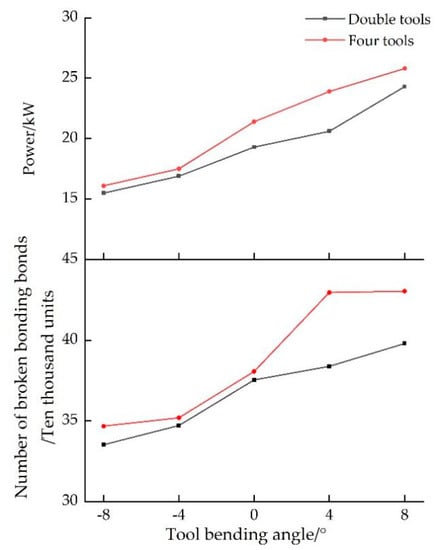
Figure 13.
Influence of tool structure parameters on test indexes.
3.1.2. Influence of Operational Parameters on Test Indexes
It was determined as described above that the operational effect of four-tool installations is obviously better than that of double-tool installations, so the next study was on the influence of the operational parameters on the test indexes for four tools. The fixed tool bending angle was 4. The forward speed was taken as 1 m·s−1, 1.5 m·s−1, and 2 m·s−1, and the tool rotation speed was taken as 260 r·min−1, 300 r·min−1, and 340 r·min−1 for the simulation test. The power consumption of the rotary tillage knives and the variation in the number of bonded bonds broken are shown in Figure 14. The broken soil effect of vertical rotary tillage was negatively related to the forward speed and positively related to the tool rotation speed; the power consumption of rotary tillage operation increased with the increase of the operating parameters.
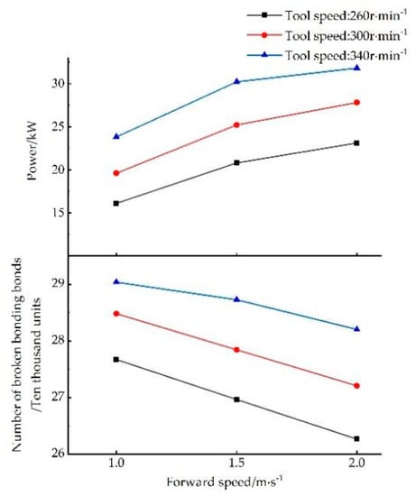
Figure 14.
Influence of operational parameters on test indexes.
3.2. Multifactor Simulation Test Analysis
3.2.1. Orthogonal Experimental Design
From the Single-Factor Analysis, it is known that the four-tool vertical rotary tillage knife is better than the two-tool installation, so the four-tool option was selected for the orthogonal test to obtain the optimal combination of parameters for the operation. The forward speed, rotation speed, and tool bending angle of the vertical rotary tillage knife were used as the test factors, and the torque, power consumption, and soil-breaking effect were used as the test indexes. The test factors and orthogonal test levels are shown in Table 4.

Table 4.
Factors and levels of the orthogonal test.
3.2.2. Analysis of Orthogonal Test Results
Three factors and three levels of orthogonal tests for different working parameters of vertical rotary tillage and tool bending angle resulted in orthogonal table L9 (33) and a total of nine sets of tests to be completed. The orthogonal test results were subjected to extreme difference analysis, as shown in Table 5.

Table 5.
Analysis of extreme differences in orthogonal test results.
The order of the factors affecting the soil-breaking effect of the vertical rotating tiller was tool-bending angle C > tool speed B > forward speed A; the order of the factors affecting the torque of the vertical rotating tiller was forward speed A > tool bending angle C > tool speed B; the order of the factors affecting the power of the vertical rotating tiller was forward speed A > tool speed B > tool-bending angle C. The test results show that the optimal combination for the vertical rotating tiller operating effect was A2B3C3; the optimal combination of torque and power consumption affecting the vertical rotary tiller was A1B1C1. Because the optimization conditions of the three indicators alone were not consistent, we had to consider the factors in order of influence to determine the best combination of the vertical rotary tiller operational parameters. The soil crushing effect was the primary consideration, so in actual operation, the optimal combination should be A2B3C3.
3.3. Soil Tank Test Results and Analysis
Two sets of soil tank verification experiments were conducted according to the combination of the parameters with the optimal operating effect and the lowest power consumption obtained from the simulation tests and were recorded as Experiment A and Experiment B. The experimental measurement results are shown in Table 6 and Table 7.

Table 6.
Experiment A measurement results.

Table 7.
Experiment B measurement results.
In the results of the soil tank experiment compared with the simulation test, the power consumption of the simulation test is 26.1 Kw and the average power consumption of the soil trough test is 27.8 Kw under the optimal combination of operating effects (forward speed 1.5 m/s, tool speed 340 r/min, tool bending angle 8°). Under the parameter combination with the lowest power consumption (forward speed of 1 m/s, tool speed of 260 r/min, tool bending angle of 0°), the power consumption of the simulation test is 13.7 Kw, and that of the soil tank test is 14.02 Kw, the power consumption value of the two groups of experiments increased by 7% and 3% compared with the simulation experiment, the average tillage depth of soil tank test under the combination of parameters with the best operational effect is 15.02 cm, and the average tillage depth of soil tank test under the combination of parameters with the lowest power consumption is 14.28 cm, the plowing depth of the operation was reduced. This was because, in the soil tank experiment, the tool was subjected to more resistance in the process of operation, while under the ideal conditions of the simulation, the resistance was a fixed value. In the simulation experiment, the tool could not achieve up-and-down movement, and the plowing depth was stabilized at 15 cm. The simulation was able to basically reflect the operation process of vertical rotary tillage. The two sets of soil trough experiments showed that when the tool bending angle is 0°, the forward speed is 1 m/s, and the tool speed is 260 r/min, the soil crushing rate is 75.2%; when the tool bending angle is 8°, the forward speed is 1.5 m/s, and the tool speed is 340 r/min, the soil crushing rate is 80.8%, the soil crushing effect has obvious improvement effect. The test indicators refer to ISO 4254-5:2018(E), for the micro cultivator working in the orchard, the soil crushing rate should be more than 70%, and the tillage depth should be more than 10 cm. The vertical rotary cultivator designed in this paper all met the agronomic tillage requirements.
4. Conclusions
In order to improve the operation effect of the vertical rototiller, a rototiller–soil model was established using the discrete element method; the soil breaking, tool torque, and power consumption during its operation were analyzed, and soil tank tests were conducted for verification.
- Simulation results show that the distribution of vertical rotary tillage knives has a significant effect on the operating effect; the operating effect of four knives was increased by up to 10.6% under the same conditions for soil crushing due to doubling the number of knives, but the power consumption was increased by 13.8%. The operating effect of the vertical rotary tillage machine was negatively related to the forward speed of the knives and positively related to the rotation speed of the knives; increasing the contact area between the knives and the soil improved the crushing effect on the soil. Increasing the contact area between the tool and the soil to improve the crushing effect on the soil by increasing the bending angle of the tool also improved the crushing effect on the soil.
- With the forward speed of the tool, tool speed, and tool bending angle as three factors, and the torque, power consumption, and soil crushing effect of the vertical rotary tillage knife as the test indexes, orthogonal tests were conducted and the best operating and structural parameters were determined via extreme difference analysis: forward speed, 1.5 m·s−1; tool speed, 340 r·min−1; and tool bending angle, 8°.
- The soil tank test showed that the average tillage depth of vertical rotary tiller operation under the optimal parameter combination was 15.02 cm and the average soil breaking rate was 80.8%, which meets agronomic tillage requirements; the actual measured power consumption was 7% higher than the simulated value, which is close, verifying the validity of the simulation results and laying the foundation for subsequent research on and optimization of the whole machine.
In this study, we mainly analyzed the effects of the operating parameters of the rotary tiller, the number of tools installed, and the bending angle of the tools on the operating effect, and conducted a soil groove verification test, providing a reference for future optimization research on the micro vertical rotary tiller.
Author Contributions
Conceptualization, S.Z. and Y.S.; methodology, Y.S.; software, S.Z. and J.Z.; validation, J.L., D.H. and A.Z.; formal analysis, S.Z.; investigation, J.Z.; resources, Y.S.; data curation, S.Z.; writing—original draft preparation, S.Z.; writing—review and editing, S.Z., Y.S. and P.J.; visualization, S.Z.; supervision, Y.S. and P.J.; project administration, Y.S.; funding acquisition, Y.S. and P.J. All authors have read and agreed to the published version of the manuscript.
Funding
This research was funded by the Excellent Youth Project of the Hunan Education Department (no. 21B0207), and the Hunan Province Science and Technology Achievement Transformation and Industrialization Plan Project (2020GK4075).
Institutional Review Board Statement
Not applicable.
Informed Consent Statement
Not applicable.
Data Availability Statement
Not applicable.
Conflicts of Interest
The authors declare no conflict of interest.
References
- Nie, S.; Zhang, H.; Zhang, Q.; Xu, J.; Zhang, Y. Effect of vertical rototilling on soil firmness and yield of wheat during the growing season. J. Agric. Resour. Environ. 2021, 38, 36–42. [Google Scholar]
- Du, Z.; Chen, Y.; Zhang, J.; Han, X.; Geng, A.; Zhang, Z. Domestic and foreign rotary tillage machinery development status and prospects. J. Chin. Agric. Mech. 2019, 40, 43–47. [Google Scholar]
- Lin, H.; He, J.; Li, H.; Li, H.; Wang, Q.; Lu, C.; Li, Y.; Jiang, S. A Review of Research Progress on Soil Organic Cover Machinery in China. Agriculture 2022, 12, 1311. [Google Scholar] [CrossRef]
- Pikul, L.; Aase, K. Water Infiltration and storage affected by subsoiling and subsequent tillage. Soil. Soc. Am. J. 2003, 67, 859–866. [Google Scholar] [CrossRef]
- Zhang, M.; Wu, C.; Chen, C. Design of vertical rotary tiller transmission system and analysis of rotary knife movement. J. Chin. Agric. Mech. 2013, 34, 66–69. [Google Scholar]
- Liu, F.; Mi, Y.; Liao, N.; Di, M.; Liu, Y.; Liu, H. Research, design and testing of vertical rotary tiller. J. Agric. Mech. Res. 2017, 39, 81–84. [Google Scholar]
- Tanaka, H.; Oida, A.; Daikoku, M. The effect of design parameters of vibrating wide subsoiler in its performance simulated by the distinct element method. In Proceedings of the 15th International Conference of the ISTVS, International Society of Terrain-Vehicle Systems, Hayama, Japan, 25–29 September 2005. [Google Scholar]
- Hofstetter, K. Analytic method to predict the dynamic interaction of dozer blade with earthen material. In Proceedings of the 14th International Conference of the ISTVS, Vicksburg, MS, USA, 6–7 October 2002. [Google Scholar]
- Zhang, R.; Li, J. Simulation on mechanical behavior of cohesive soil by distinct element method. J. Terramech. 2006, 43, 303–316. [Google Scholar] [CrossRef]
- Momozu, M.; Oida, A.; Yamazaki, M. Simulation of a soil loosening process by means of the modified distinct element method. J. Terramech. 2003, 39, 207–220. [Google Scholar] [CrossRef]
- Yu, J.; Qian, L.; Yu, W.; Pan, S.; Fang, Y.; Fu, H. DEM analysis of the resistance applied on furrow openers. Trans. Chin. Soc. Agric. Mach. 2009, 40, 53–57. [Google Scholar]
- Chen, Y.; Munkholm, J.; Nyord, T. A discrete element model for soil-sweep interaction in three different soils. Soil Tillage Res. 2013, 126, 34–41. [Google Scholar] [CrossRef]
- Tamás, K.; Jóri, J.; Mouazen, M. Modelling soil-sweep interaction with discrete element method. Soil Tillage Res. 2013, 134, 223–231. [Google Scholar] [CrossRef]
- Fang, H.; Ji, C.; Tagar, A.; Zhang, Q.; Guo, J. Analysis of straw movement in straw-soil-rotary blade system. Trans. Chin. Soc. Agric. Mach. 2016, 47, 60–67. [Google Scholar]
- Ucgul, M.; Fielke, M.; Saunders, C. Three-dimensional discrete element modelling of tillage: Determination of a suitable contact model and parameters for a cohesionless soil. Biosyst. Eng. 2014, 121, 105–117. [Google Scholar] [CrossRef]
- Ucgul, M.; Fielke, M.; Saunders, C. 3D DEM tillage simulation: Validation of a hysteretic spring(plastic)contact model for a sweep tool operating in a cohesionless soil. Soil Tillage Res. 2014, 144, 220–227. [Google Scholar] [CrossRef]
- Marenya, O. Performance Characteristics of a Deep Tilling Rotavator; University of Pretori: Pretoria, South Africa, 2009. [Google Scholar]
- Salokhe, M.; Ramalingam, N. Effect of rotation direction of a rotary tiller on draft and power requirements in a Bangkok clay soil. J. Terramech. 2003, 39, 195–205. [Google Scholar] [CrossRef]
- Iwasaki, K.; Miyabe, Y.; Kashiwagi, S. Tillage resistance on tip and straight portion of a rotary blade. Mem. Fac. Agric. Kagoshima Univ. 1992, 28, 143–151. [Google Scholar]
- Asl, H.; Singh, S. Optimization and evaluation of rotary tiller blades: Computer solution of mathematical relations. Soil Tillage Res. 2009, 106, 1–7. [Google Scholar] [CrossRef]
- Tang, W.; Liu, E.; He, C.; Jin, C.; Liu, C. Design and testing of vertical rotary tiller. J. Agric. Mech. Res. 2022, 44, 77–81+87. [Google Scholar]
- Xu, Y.; Li, H.; Huang, W. Three-dimensional discrete element modeling and simulation scenario planning for tilled soil dynamics. Trans. Chin. Soc. Agric. Eng. 2003, 2003, 34–38. [Google Scholar]
- Mak, J.; Chen, Y.; Sadek, M. Determining parameters of a discrete element model for soil-tool interaction. Soil Tillage Res. 2012, 118, 117–122. [Google Scholar] [CrossRef]
- Ting, M.; Corkum, T.; Kauffman, R. Discrete numerical model for soil mechanics. J. Geotech. Eng. 1989, 115, 379–398. [Google Scholar] [CrossRef]
- Da, Q.; Li, D.; Zhang, X.; Guo, W.; He, D.; Huang, Y.; He, G. Research on Performance Evaluation Method of Rice Thresher Based on Neural Network. Actuators 2022, 11, 257. [Google Scholar] [CrossRef]
- Potyondy, D.; Cundall, P. A bonded-particle model for rock. Int. J. Rock Mech. Min. Sci. 2004, 41, 1329–1364. [Google Scholar] [CrossRef]
- Zhao, Z.; He, X.; Shang, S.; Hou, J.; Zhu, H.; Wang, H.; Wang, Y.; Li, D.; Chang, Z.; Xia, C.; et al. Design and Testing of Discrete Element-Based Counter-Rotating Excavation Device for Cyperus esculentus. Agriculture 2022, 12, 1608. [Google Scholar] [CrossRef]
- Hu, G. Analysis and Simulation of Particle System by Discrete Element Method Using EDEM; Wuhan University of Technology Press: Wuhan, China, 2010. [Google Scholar]
- Cundall, P.A.; Strack, O.D.L. A discrete numerical model for granular assemblies. Geotechnique 1979, 29, 47–65. [Google Scholar] [CrossRef]
- Sakaguchi, H.; Ozaki, E.; Igarashi, T. Plugging of the flow of granular materials during the discharge from a silo. Int. J. Mod. Phys. B 2012, 7, 1949–1963. [Google Scholar] [CrossRef]
- Wu, Z.; Xie, F.; Wang, X.; Liu, D.; Looh, A.; Zhang, Z.; Tang, Q. Calibration of discrete element parameters and experimental verification for modelling subsurface soils. Biosyst. Eng. 2021, 212, 215–227. [Google Scholar] [CrossRef]
- Zhu, Z. Soil Science Volume I; Beijing China Agricultural Publishing House: Beijing, China, 1983. [Google Scholar]
- Xie, F.; Wu, Z.; Wang, X.; Liu, D.; Wu, B.; Zhag, Z. Calibration of discrete element parameters of soils based on unconfined compressive strength test. Trans. Chin. Soc. Agric. Eng. 2020, 36, 39–47. [Google Scholar]
- Yang, W.; Wu, B.; Peng, Z.; Tang, Z. Evaluation of trenching quality of vertical screw trencher based on discrete element method. J. Southwest Univ. (Nat. Sci. Ed.) 2019, 12, 1. [Google Scholar]
- Anonymous. Dahua Baolai JBQ series heavy-duty drive rake. Agric. Mach. 2020, 29. [Google Scholar] [CrossRef]
- Gai, C.; Dong, Y. COSMOS-based optimization of bending angle of rotary tillage cutter for return machine. J. Agric. Mech. Res. 2011, 33, 30–33. [Google Scholar]
- He, Z.; Xin, H. Exploration of the rules of rotary tiller blade arrangement. Contemp. Farm Mach. 2000, 2000, 20–21. [Google Scholar]
Publisher’s Note: MDPI stays neutral with regard to jurisdictional claims in published maps and institutional affiliations. |
© 2022 by the authors. Licensee MDPI, Basel, Switzerland. This article is an open access article distributed under the terms and conditions of the Creative Commons Attribution (CC BY) license (https://creativecommons.org/licenses/by/4.0/).