1. Introduction
Giant magnetostrictive material [
1,
2] (GMM) is regarded as the strategic intelligent material of science and technology in the 21st century, and it has the following advantages compared with traditional magnetostrictive material:
The saturation magnetostriction coefficient (λS) is large. When the applied magnetic field is strong enough, GMM reaches the maximum stretching strain, and its magnetostriction coefficient is hundreds of times that of traditional magnetostrictive materials (Ni: 35~40 ppm, FeCoV: 60~120 ppm, etc.) at room temperature. Taking the < 112 > oriented Terfenol-D material as an example, its saturated magnetostriction coefficient can reach 1500~2000 ppm.
The magneto-mechanical coupling coefficient (K33) is large. The magneto-mechanical coupling coefficient represents the efficiency of materials in converting magnetic field energy into mechanical energy. The GMM magneto-mechanical coupling coefficient is 2~3 times that of traditional magnetostrictive materials, and it has become the first-choice material for realizing a magneto-mechanical energy conversion.
The response speed is fast and can reach the µs level. It can be used to design and manufacture quick-acting components, such as high-speed on-off valves.
It has a good frequency bandwidth and low frequency characteristics. It is better at meeting the requirements of a low frequency operation, and has a high energy conversion efficiency in the range of 0~5 kHz.
It has a higher Curie temperature. The material has a better temperature stability and can adapt to higher-temperature working areas above 200 °C.
At present, GMM has been widely used in sonar, micro-displacement drive, vibration reduction and anti-vibration, robots, smart wings, spacecraft, valves and other technical fields. Among these, the giant magnetostrictive actuator (GMA) developed by using GMM as the transducing element effectively inherits the excellent characteristics of GMM, and it shows a good driving effect in electronically controlled injectors.
However, the application of GMA in electronically controlled injectors is mostly limited to the non-direct drive structure [
3,
4,
5,
6,
7], and its inherent problems, such as a long oil circuit and a difficult precise control of the needle valve stroke, are difficult to effectively solve. There are few studies on the direct-drive structure [
8,
9,
10], and they all stay in the conceptual machine or simulation research stage. Therefore, based on the structure of the direct-drive injector combined with the driving requirements of the injector and the working characteristics of GMA, it is of great significance to design an actuator for the direct-drive giant magnetostrictive injector and carry out related research work to improve the injection performance of the electronically controlled injector. In addition, considering that the traditional GMA [
11,
12,
13] model has a high calculation accuracy but that its form is complex and difficult to solve, which is not conducive to the integrated modeling of subsequent injectors, in order to meet the demand of GMA applied to electronically controlled injectors, the GMA model (especially the magnetization model with the strongest nonlinearity) should be appropriately simplified under the condition of a certain calculation accuracy.
Based on the structure of the direct-drive injector, GMM is used as the transduction material, and the actuator for the direct-drive injector is designed under the condition of meeting the opening displacement requirement of the injector needle valve, taking into account the output displacement direction requirement of GMA when the injector is energized. With the current as the input, the internal magnetic field of GMA is equivalent to the magnetic circuit, and the magnetic field intensity on GMM is analyzed and calculated. Based on the Jiles-Atherton modified simplified magnetization model, the displacement output model of GMA is established by combining the quadratic domain transition model and the single-degree-of-freedom vibration model. An experimental test system was built to verify the GMA theoretical model.
2. Actuator Structure and Modeling
2.1. GMA Structure and Working Principle
The GMA structure of the designed direct-drive injector is shown in
Figure 1.
Within it, the GMM is designed as a cylinder structure, which is matched with the T-shaped plunger to realize the conversion of output displacement, and the elongation of the GMM cylinder is converted into the shortening of GMA output displacement. The working principle is: after electrifying, the excitation coil generates a magnetic field, and the GMM cylinder stretches under the action of the magnetic field to push the T-shaped plunger into moving upward against the force of the disc spring; after the power failure, the magnetic field intensity gradually decreased, the GMM cylinder was shortened, and the “T” plunger was reset under the action of the disc spring.
The main parameters of GMA are shown in
Table 1 [
14]. Considering the GMM material performance parameters, material price and other factors, this paper chooses cylindrical GMM from Suzhou Evan Special Alloy Co., Ltd.
2.2. GMA Modeling
According to the coupling degree of the electric field, magnetic field and mechanical field in GMA, the GMA model can be divided into a strong coupling model and weak coupling model [
12,
13,
14]. Of these, the weak coupling model is modeled according to, successively, the magnetic field model, magnetization model, magnetostriction model and dynamics model, and the relationship between the key physical quantities is clear so that the model is easy to solve. Because the subsequent integrated modeling of the giant magnetostrictive injector is complicated, the GMA model should not be too complicated, so the modeling method shown in
Figure 2 is adopted to establish the model. The following four assumptions are followed when establishing the model:
The magnetic field intensity generated by the excitation coil is evenly distributed along the axial direction of the GMM cylinder, and the axial magnetization, magnetostrictive strain and stress on the GMM cylinder are evenly distributed.
Considering the GMM cylinder as a mass-spring-damping element, the whole GMA can be equivalent to a single-degree-of-freedom vibration system.
Because of the existence of the disc spring, GMA is a semi-closed magnetic circuit. In the magnetic circuit, the parallel magnetic circuit (that is, the GMM cylinder) can distribute most of the magnetic potential because the GMM cylinder and the T-shaped plunger are connected in parallel and the GMM magnetic resistance is large.
During the GMA operation, the “T” plunger and GMM cylinder are always attached, so they can move synchronously.
Traditional GMA model research is relatively mature and can accurately describe its working characteristics. However, the related models are relatively complex, especially the hysteresis model of GMM, which renders the model calculation and the subsequent control of the actuator difficult. Therefore, this paper reasonably simplifies the model and establishes a simple and effective GMA model, in order to make the application of GMA to the control of the direct-drive injector convenient.
2.2.1. Magnetic Circuit Model
To study the magnetic field intensity on the GMM cylinder, the internal magnetic field of GMA can be equivalent to the magnetic circuit [
15], and its principle is similar to the circuit theory: the parallel magnetic circuits have the same magnetic potential, and the main magnetic flux is equal to the sum of the magnetic fluxes of each branch; the magnetoresistance, magnetomotive force and magnetic flux in the magnetic circuit correspond to the resistance, electromotive force and current in the circuit, respectively. As GMA is an axisymmetric structure, correspondingly, the equivalent magnetic circuit is a symmetrical magnetic circuit. For the convenience of research and analysis, one side of the axial section is taken as the research object, and the schematic diagram of the GMA magnetic circuit is shown in
Figure 3.
A magnetic field is generated when current is passed through the coil, and magnetic lines of force flow through the shell, GMM, T-shaped plunger and air layer, respectively, to form a semi-closed magnetic circuit. According to the different materials, lengths and cross-sectional areas, GMA magnetic circuits can be divided into multiple segments of magnetoresistance. For any segment of magnetoresistance, there are:
R is magnetoresistance,
l is the length of the magnetic segment,
µ is the material permeability,
S is the cross-sectional area of the magnetic segment, and
i represents different magnetic segments. As the “T” plunger and GMM cylinder are parallel magnetic circuits, the following can be obtained:
where
H is the magnetic field intensity of the GMM cylinder,
C is the proportion of the magnetic potential of the GMM cylinder and T-shaped plunger to the total magnetic potential,
N is the number of turns of the magnetic coil, and
l is the length of the GMM cylinder.
2.2.2. Jiles-Atherton Magnetization Model
For GMA used in a fuel injector, the driving magnetic field is large and the frequency is low, so the hysteresis between the magnetization and magnetic field intensity is not obvious. At the same time, when GMA works, the current-voltage hysteresis and the displacement-strain hysteresis are much larger than the hysteresis, and the superposition of these links renders the hysteresis effect slighter. Therefore, for GMA for a fuel injector, it is not necessary to consider the hysteresis characteristics of magnetization when establishing the magnetization model.
The amplitude characteristics and change trend of magnetization directly determine the calculation results of the response amplitude and response speed, and these characteristics must be retained when modeling. Considering that the amplitude of magnetization
M in the J-A model [
16,
17,
18] is roughly equal to that of non-hysteresis magnetization
Man [
19,
20] and that the curve change form is also roughly the same (mainly determined by the shape parameter
a), the magnetization can be simplified according to the expression of
Man, that is, the expression of approximate
M is:
where
α is the domain wall interaction coefficient,
MS is the saturation magnetization, and
is the langevin function.
The fixed-point iteration method is used to calculate the formula, and the calculation format is:
where
is the initial value of the magnetization,
is the number of iterations of the fixed method, and
is the maximum number of iterations.
2.2.3. Magnetostrictive Strain Model
Based on the results of
Section 2.2.2, the hysteresis expansion strain on the GMM cylinder can be obtained, which is usually calculated by the quadratic domain transfer model:
where
is the magnetostriction strain,
is the saturation magnetostriction coefficient, and
is the saturation magnetization.
2.2.4. Dynamic Model
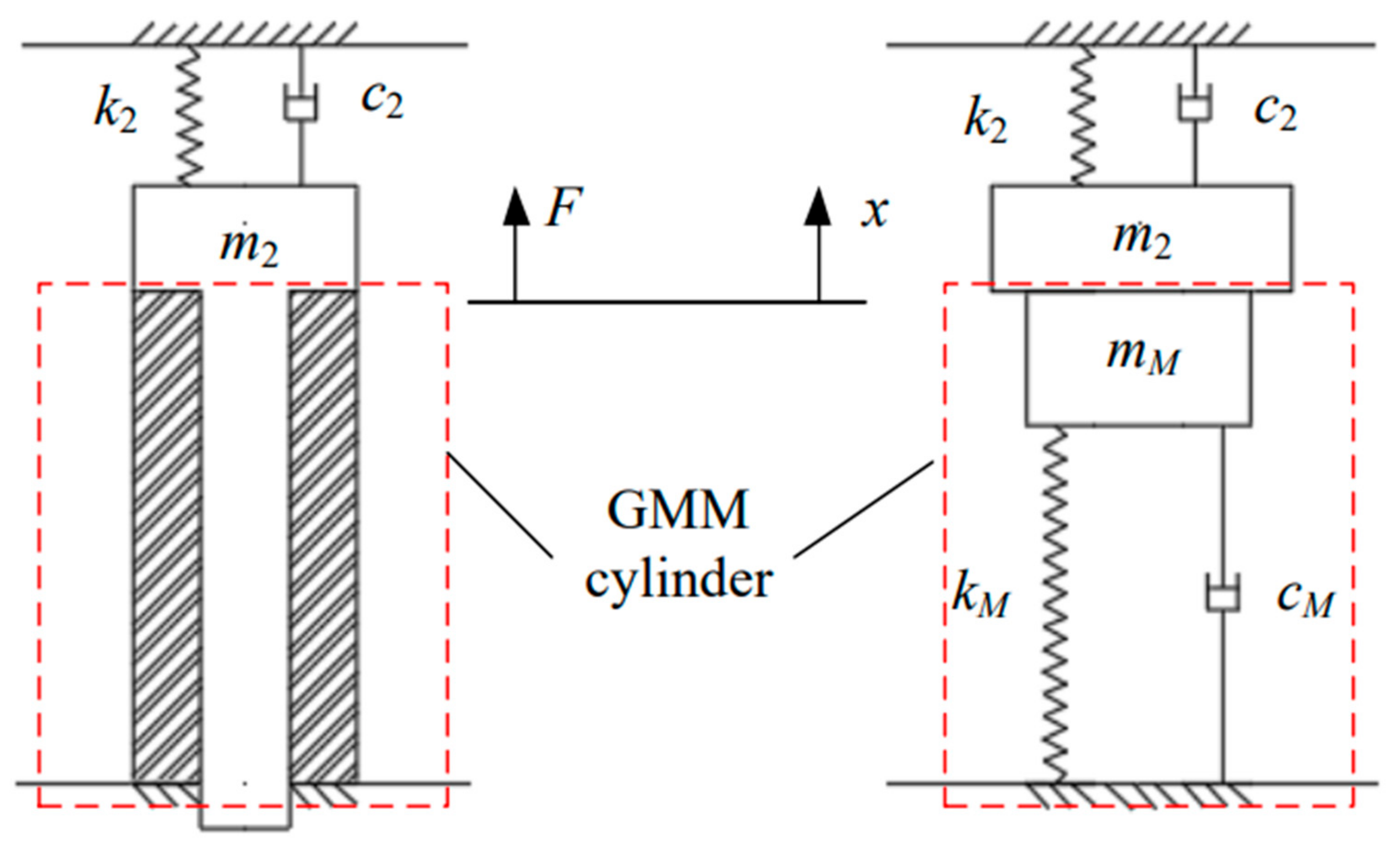
After GMA is electrified, the GMM cylinder can be regarded as a mass-spring-damping element. Based on the assumption (4), GMA can actually be equivalent to a single-degree-of-freedom vibration system, as shown in
Figure 4.
When GMA is not powered on, the “T” plunger is located at the bottom of the working stroke, the joint of the “T” plunger and GMM cylinder is taken as the displacement zero point, and the coordinate system is established with the positive direction being upward:
where
F is the magnetostrictive force,
E is the elastic modulus of GMM, and
A is the cross-sectional area of the GMM cylinder;
m2,
c2 and
k2 are the “T” plunger mass, damping coefficient and disc spring stiffness, respectively, and
,
and
are the equivalent mass, equivalent damping coefficient and equivalent stiffness of the GMM cylinder, respectively, for which, using the Rayleigh method, it is known that the equivalent mass of GMM, cylinder to cylinder end, is approximately
mM/3 and that
cm can be obtained by parameter identification.
By sorting out the above three formulas and by making
m,
c and
k represent the sum of the mass, damping and stiffness, we can obtain:
The output displacement response of GMA when the input current is
I can be obtained by the above equations. In this paper, MATLAB mathematical software is used to solve the model. When a sinusoidal signal with a frequency of 20 Hz and an amplitude of 5A is input, the step time is 100 µs and 20 µs and the calculation time of the model is 4.643s and 93.158s, respectively. The comparison of the displacement output of the model is shown in
Figure 5. The results show that the curves are in good agreement with each other, and the relative errors between them are all less than 1% by calculating the data points at multiple peaks. Considering the accuracy and rapidity of the model calculation, the step time is 100 µs in the subsequent solution of the model.
3. Experimental Verification
3.1. Physical Object and Test System
Based on the GMA structure designed in
Figure 1, the GMA prototype was fabricated, as shown in
Figure 6. Within it, GMM is a cylindrical structure using single crystal Terfenol-D material (< 110 >) produced by Gansu Tianxing Rare Earth Co., Ltd.; additionally, the “T” plunger, pre-tightening bolt, end cover and shell are all made of 45# steel with a high permeability.
The no-load output displacement of GMA was measured by the test system shown in
Figure 7. The testing principle is as follows: the electric signal generated by the signal source is amplified by the power amplifier and then input into GMA, the GMA outputs the displacement after being electrified, and the displacement is measured and captured by a laser displacement sensor. Meanwhile, the GMA coil current can be collected by the current clamp, and the test principle’s block diagram is shown in
Figure 8. The devices and models used in the experiment are as follows: signal generator (RIGOL DG1022U), power amplifier (SA-PA020), oscilloscope (PS2000) and laser displacement sensor (LTS-025-02). The computer collects and stores the electrical signals of the GMA output displacement and coil current by using Pico software.
3.2. Modelling Verification
Considering that square waves can often be converted into a superposition of low-frequency sine waves and that sine waves are more comprehensive, this paper adopts low-frequency sine waves for the experimental verification.
The signal sources respectively output sinusoidal voltage signals with a frequency of 20 Hz and adjust the gain of the power amplifier to change the current value of the GMA internal coil. When the input current is 2A, 3A, 4A and 5A, the experimental test results and model calculation results are shown in
Figure 9a–d. Because the bias magnetic field is not designed in the device, the phenomenon of “frequency doubling” appears in the results. The results show that the established model can track the experimental curve well and that it has a certain accuracy in calculating the output displacement amplitude, describing the variation relationship between the amplitudes and the phase difference between the input and output. To further verify the accuracy of the model, the frequency response characteristics of GMA are analyzed below.
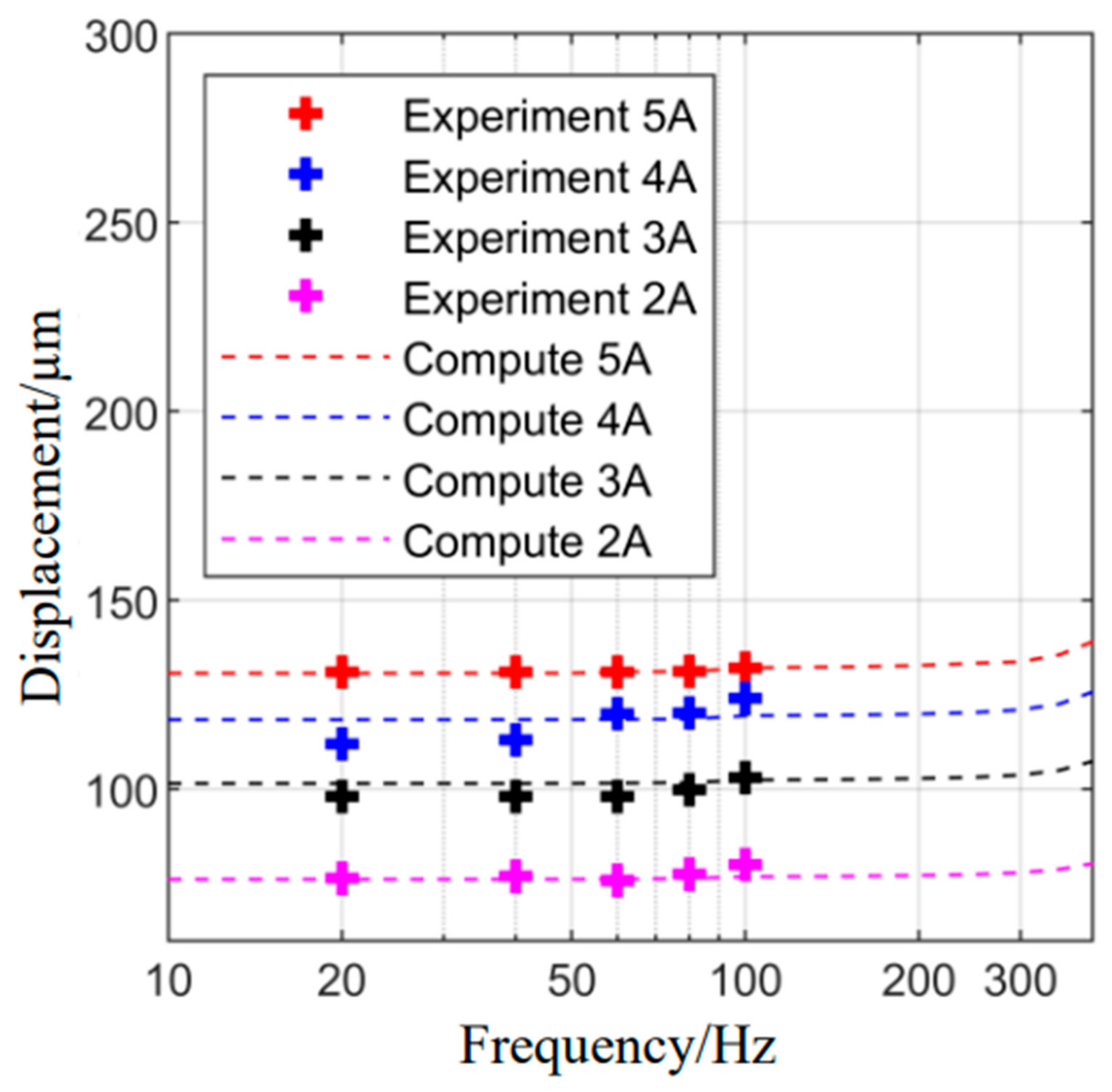
We input a sinusoidal alternating current with amplitudes of 2, 3, 4 and 5 A and frequencies of 20, 40, 60, 80 and 100 Hz, respectively, and obtain the GMA amplitude-frequency response curve shown in
Figure 10. The results show that the experimental results are in good agreement with the calculated results of the model, and the average relative error is 3.26%. In the frequency range of 0~100 Hz, the amplitude change is not obvious. This is because the resonance frequency of GMA is high, and the theoretical calculation can reach a magnitude of 103.
Because the GMM material shows an increase of the axial dimension when applied with a magnetic field in the positive and negative directions, GMA shows the “frequency doubling” effect under the action of a sinusoidal current. Through the analysis of the whole modeling process, the “frequency doubling” effect occurs in the magnetostrictive strain link. In this link,
M is a sine signal, and because of the
M2 term, the alternating current signal becomes a direct current signal, which leads to “frequency doubling”. As shown in
Figure 11, the red curve is a sine signal, the blue curve is the square of the sine signal, and the black dotted line is a schematic curve of phase lag. It can be found that the red curve and the blue curve have highly consistent variation laws in the positive interval of the sine function (sin(ωt+φ)≥0), and there is no phase difference between them in this interval, but the black dotted line shows it. On the other hand, due to the high resonance frequency of GMA, the phase lag will not exceed π/2 in the frequency range of 0~100 Hz. Therefore, to analyze the phase difference between the current signal and the displacement signal, a reasonable scheme is to calculate the peak position of the two signals in the positive interval of the sine function.
The GMA phase-frequency characteristic curve is shown in
Figure 12. When comparing the experimental results with the model calculation results, it is found that they are in good agreement with each other and that the average relative error is less than 5%. The model calculation results can describe the GMA phase difference and the relationship between the phase difference and frequency well. On the other hand, the phase difference calculated by the model is slightly smaller than the experimental results, which is mainly due to the mechanical clearance of GMA and the fact that hysteresis is not considered when establishing the mathematical model.
Due to the limitation of the experimental conditions, the stable working current of GMA can only reach 5 A. Under the condition that the model is verified by experiments, intermediate variables such as the GMM cylinder magnetic field strength and magnetostrictive strain can be conveniently calculated by the model. When the input current is 5 A, the magnetic field intensity and magnetostrictive strain on the GMM cylinder are shown in
Figure 13. For the convenience of observation, the corresponding variable values are scaled appropriately. The results show that when the current amplitude is 5 A, the magnetic field intensity amplitude is about 5.6 × 10
4 A/m and the magnetostrictive strain amplitude is about 791 ppm. This shows that the material is close to saturation, and it is difficult to further improve the displacement output by increasing the current intensity. The driving magnetic field should make the magnetic field intensity on the GMM cylinder not be under 5.6 × 10
4 A/m.
4. Conclusions
Based on the driving demand of a small-flow fuel injector combined with the structural characteristics of a direct-drive fuel injector, GMA with a reasonable structural form was designed with GMM as the core transduction material. With the current as the input of the GMA system, the T-shaped plunger displacement as the output, and no hysteresis magnetization as the total magnetization, a simplified displacement output model of GMA is established. The GMA prototype was fabricated, and the output displacement test system was built. The frequency characteristics of the two were obtained through an experimental test and model solution, and the theoretical model was verified.
By solving the theoretical model and experimental test, it is found that when the sinusoidal alternating current with an amplitude of 2 A and frequency of 0~100 Hz is input, the output displacement of GMA can reach 75 μm, which far exceeds the driving displacement (30 μm) required by the pilot valve of a non-direct-drive injector. When the input current amplitude is 5 A and the frequency is 0~100 Hz, the output displacement can reach 130 μm, which meets the design requirements. The GMA designed in this paper is expected to meet the driving demand of a small-flow injector, realize the precise control of a needle valve stroke, and enhance the flexibility of injection rate adjustment. The results show that for the application of the J-A model in a low-frequency scene, it is feasible to use the non-hysteresis magnetization as the total magnetization, which is consistent with the experimental results. This lays a solid foundation for the integrated modeling of a follow-up electronically controlled injector and other research.
At the same time, it should be noted that due to the fact that hysteresis and mechanical clearance are not considered in this paper, there are still some shortcomings in the description of the phase lag. Furthermore, the current research is mainly aimed at GMA, not the whole fuel injector. Related working environment factors such as temperature and oil pressure have not been considered, but they will gradually be added to follow-up fuel injector research.
Author Contributions
Conceptualization, Z.H. and G.X.; methodology, Z.Z.; software, Z.Z.; validation, Z.Z., C.R. and G.L.; formal analysis, Z.Z.; investigation, Z.Z.; resources, J.Z.; data curation, J.Z.; writing—original draft preparation, Z.Z.; writing—review and editing, Z.Z.; visualization, J.Z.; supervision, Z.H.; project administration, Z.H.; funding acquisition, J.Z. All authors have read and agreed to the published version of the manuscript.
Funding
This research received no external funding.
Institutional Review Board Statement
Not applicable.
Informed Consent Statement
Not applicable.
Data Availability Statement
Not applicable.
Conflicts of Interest
The authors declare no conflict of interest.
References
- Zhou, S.; Gao, X. Magnetostrictive Materia, 1st ed.; Metallurgical Industry Press: Beijing, China, 2017; pp. 1–10. [Google Scholar]
- Engdahl, G. Handbook of Giant Magnetostrictive Materials; Academic Press: San Diego, CA, USA, 2000. [Google Scholar]
- Liu, H.; Zhao, J.; Wang, W. Study on Model and Characteristics Analysis of the Magnetostrictive Drive Component of Automotive Fuel Injection System. Chin. J. Sens. Actuators 2016, 29, 1797–1803. [Google Scholar]
- Wang, W.; Han, H.; Han, L.; Zhang, Y. A Model of Giant Magnetostrictive Actuator Used in Automobile Engine Fuel Injection System. Int. J. Serv. Comput. Oriented Manuf. 2013, 1, 154–166. [Google Scholar] [CrossRef]
- Tanaka, H.; Sato, Y.; Urai, T. Development of a Common-Rail Proportional Injector Controlled by a Tandem Arrayed Gi-ant-Magnetostrictive-Actuator; 2001-01-3182, SAE Technical Paper; SAE International: Warrendale, PA, USA, 2001. [Google Scholar]
- Sato, Y.; Tanaka, H.; Fuseya, T. Characteristics of a Proportional Injector for Common Rail Injection System: 1st Report, In-jection Characteristics by a Switching Pilot-valve. Trans. JSME Ser. C 2000, 66, 1857–1860. [Google Scholar] [CrossRef] [Green Version]
- Xue, G.; Zhang, P.; He, Z. Design and Modeling of the Giant Magnetostrictive Injector. Trans. CSICE 2019, 37, 337–342. [Google Scholar] [CrossRef]
- Brignt, C.B.; Garza, J.C. Possible Very High Speed Rate Shaping Fuel Injector; 2007-01-4113; SAE Technical Paper; SAE International: Warrendale, PA, USA, 2007. [Google Scholar]
- Brignt, C.B.; Faidley, L.; Witthauer, A. Programmable Diesel Injector Transducer Test Results; 2011-01-0381; SAE Technical Paper; SAE International: Warrendale, PA, USA, 2011. [Google Scholar]
- Xu, B. Structure Design and Characterstic Analysis of High Pressure Common Rail Injector Based on Giant Magnetostrictive Actuator; Anhui University of Science and Technology: Huainan, China, 2020. [Google Scholar]
- Cao, Q.; Chen, D.; Li, C. A review of the magnetomechanical modeling of magnetostriction materials. In Proceedings of the Joint International Conference on Pervasive Computing and the Networked World (ICPCA/SWS 2013), Vina del Mar, Chile, 5–7 December 2014; pp. 1–7. [Google Scholar]
- Wang, T.; Zhou, Y. Nonlinear dynamic model with multi-fields coupling effects for giant magnetostrictive actuator. Int. J. SolidsStruct. 2013, 50, 2970–2979. [Google Scholar] [CrossRef] [Green Version]
- Peng, H.; Chen, Y.; Wu, Y. Research on transient multi-field coupling model of GMM under variable pressure in embedded GMA. AIP Adv. 2021, 11, 15038. [Google Scholar] [CrossRef]
- Xue, G.; Zhang, P.; He, Z.; Li, B.; Rong, C. Design and model for the giant magnetostrictive actuator used on an electronic controlled injector. Smart Mater.Struct. 2017, 26, 5. [Google Scholar] [CrossRef]
- Zhou, J.; He, Z.; Shi, Z. Design and experimental performance of an inertial giant magnetostrictive linear actuator. Sens. Amd Actuator A Phys. 2020, 301, 111771. [Google Scholar] [CrossRef]
- Jiles, D.C.; Atherton, D.L. Theory of ferromagnetic hysteresis. J. Magn. Magn. Mater. 1986, 61, 48–60. [Google Scholar] [CrossRef]
- Jiles, D.C.; Atherton, D.L. Theory of ferromagnetic hysteresis. J. Appl. Phys. 1984, 55, 2115–2120. [Google Scholar] [CrossRef]
- Jiles, D.C.; Atherton, D.L. Ferromagnetic hysteresis. IEEE Trans. Magn. 1983, 19, 2183–2185. [Google Scholar] [CrossRef]
- Xue, G.; Zhang, P.; He, Z.; Li, D.; Yang, Z.; Zhao, Z. Modification and numerical method for the Jiles-Atherton hysteresis model. Commun. Comput. Phys. 2017, 21, 763–781. [Google Scholar] [CrossRef]
- Xue, G.; Zhang, P.; He, Z.; Li, D. Approximation of anhysteretic magnetization and fast solving method for Jile-Atherton hysteresis equation. Ferroelectrics 2016, 502, 197–209. [Google Scholar] [CrossRef]
| Publisher’s Note: MDPI stays neutral with regard to jurisdictional claims in published maps and institutional affiliations. |
© 2022 by the authors. Licensee MDPI, Basel, Switzerland. This article is an open access article distributed under the terms and conditions of the Creative Commons Attribution (CC BY) license (https://creativecommons.org/licenses/by/4.0/).


