Abstract
The consistency of the two-phase mode responses is essential to ensure the mechanical performance and stability of traveling-wave ultrasonic motors. Due to the asymmetry of the stator, inevitable manufacturing errors, or imbalance of the excitation voltages, the amplitudes of the two-phase standing waves cannot be exactly the same, resulting in unstable operating of USM. To improve the stability of the motor and decrease the velocity fluctuation, a closed-loop velocity control scheme considering two-phase consistency compensation based on the vibration amplitude of the stator is proposed. This scheme is implemented under the framework of the stator vibration amplitude-based velocity control and parallel resonance frequency tracking (VCBVF). Based on the relationship between the velocity and stator vibration amplitude (SVA), two-phase excitation signals are adjusted individually and simultaneously. Compared with the single-phase feedback VCBVF control scheme, experimental results show that the proposed scheme can reduce the overshoot from 17.50% to 6.90% and velocity fluctuations from 7.69 rpm to 2.40 rpm, under different load torques. The proposed scheme can compensate for the two-phase electrical inconsistency and improve the velocity stability and output power of motor operation under various conditions.
1. Introduction
Traveling-wave rotary ultrasonic motors (TRUSMs) convert electric energy into the micro-amplitude vibration of the stator by using the reverse piezoelectric effect of piezoelectric material and transform the vibration of the stator into the rotational motion of the rotor via friction. They are widely used in optical instruments, medical and biological instruments, and aerospace due to their advantage of quietness, no electromagnetic interference, and quick response [1,2,3,4].
As is known to many, to ensure the stable operation of the TRUSM, the frequencies and amplitudes of two standing waves must be identical. However, due to material inhomogeneity, parts processing and assembly errors, or the imbalance of the two-phase excitation voltages, it will be difficult to ensure the amplitudes of the two-phase standing waves are exactly the same [1]. The traveling wave excited in the stator will then distort, which will affect the stability and efficiency of the motor. For certain applications of USM, such as biomedical devices [5], robotic arms [6], microscopy stages [7], and medical operations [8], precise and stable motion is especially required [9].
The consistency of the two-phase modes of the USMs is essential to ensure the mechanical performance and stability of the ultrasonic motor. To avoid the distortion of waves and adjust the modal frequency consistency of the two phases of the stator, Zhao et al. proposed a method of adding mass and stiffness at the appropriate position on the stator through the structural dynamic modification method and adjusting the two-phase consistency from the mechanical structure [10]. Wang et al. considered the impact of pressure imbalance along the circumference and proposed a scheme to realize pressure auto-balance with single bearing and self-aligning structure [11]. The above methods are all aimed at the adjustment of the mechanical characteristics and mechanical structure of the motor.
From the excitation signals perspective, Yang et al. introduced a BTW principle that combines beat vibration with a traveling wave using two annular standing waves of different frequencies [12]. However, the waveform, with periodic variation of both amplitude and propagation directions, is not appropriate to the stable velocity control of the motor. The practical potential application needs to be further studied. Sun et al. proposed the coordinated regulation of dynamically controlling one phase mode by referencing the other phase to optimize the motor operation state [13]. However, the targeted closed-loop control for the output characteristics of the motor (such as velocity, torque, or position) is not conducted. As for the velocity control of USMs, different control algorithms are proposed due to the nonlinearity and the resonance frequency drift of TRUSMs, such as two-input sliding model control [14], multi-parameter speed control model [15], fuzzy logic control [16], nonlinear Hammerstein model [17], and velocity control based on the stator vibration amplitude [18]. To improve the dynamic performance and efficiency of TRUSMs under various conditions, Fang et al. proposed a velocity control scheme based on the stator vibration amplitude and parallel resonant frequency tracking (VCBVF) of TRUSMs [18]. However, the difference between the two phase vibration modes and matching structures is ignored, and the feedback signal of only one phase is detected to conduct the control of the two-phase sinusoidal excitation voltages. This single-phase feedback scheme can result in unstable operating and large velocity fluctuations of USM. The instability and fluctuations cannot ensure the operation of medical instruments or microrobots, both of which generally require highly precise motion work within a tight space. Therefore, an improved velocity control scheme, considering the difference between the two-phase excitation, needs to be developed.
In this paper, a closed-loop velocity control scheme based on the two-phase stator vibration amplitude of TRUSMs is proposed to compensate for the two-phase drive excitations from the perspective of electrical drive control. The implementation of the proposed scheme is based on the framework of VCBVF. Two transformer ratio-arm bridges without feedback electrodes are used to detect the two-phase SVA. First, based on the structure and operating mechanism of the TRUSM, the influence of two-phase standing wave amplitude difference on stator’s surface particle motion is analyzed. Then, a closed-loop velocity control scheme, based on the two-phase stator vibration amplitude of TRUSMs, is proposed. The specific implementation of the scheme, including hardware and control structure, is introduced. Finally, the proposed scheme is verified and compared with the single-phase feedback control scheme by the USM Shinsei-USR60 and a self-designed experimental platform.
2. Theoretical Analysis
2.1. Structure and Operating Mechanism of TRUSM
The TRUSM is a typical and widely used USM, using the reverse piezoelectric effect of piezoelectric element. The structure diagram of the USM is shown in Figure 1, and is mainly composed of the stator, rotor, friction material, piezoelectric element, bearing, etc. The stator, friction material, and rotor are in close contact under the action of preload. When two-phase AC voltages with the same amplitude, the same frequency, and a 90° phase difference are applied on the piezoelectric element polarized in a specific way, the modal responses of the two-phase with a difference of in space and time can be excited. The two orthogonal modal responses superimpose on the stator to form a pure continuous circular traveling wave. Under the action of friction and the traveling wave, the stator will drive the rotor to move in the opposite direction of the traveling wave [1].
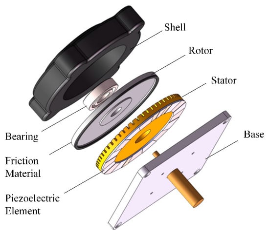
Figure 1.
The structure diagram of the USM.
The modal responses with the same frequency on the stator can be expressed as
where and are the excitation response amplitudes of A-phase and B-phase, respectively, and (rad/s) is the two-phase excitation angular frequency. (rad) is the phase difference between the two-phase response and and represent displacement function along the circumferential direction.
If two-phase voltages are simultaneously applied to two groups of the annular piezoelectric ceramic element, according to the superposition theorem, the displacement response of the stator can be expressed as
It can be noted from Equation (2) that the displacement response on the stator consists of three parts: a forward traveling wave, a backward traveling wave, and a standing wave. When and , a pure traveling wave is excited on the stator as . When the above conditions are not met, pure traveling waves cannot be excited on the stator.
2.2. Influence of Two-Phase Standing Wave Amplitude Difference on Stator’s Surface Particle Motion
To obtain a “pure” traveling wave, two orthogonal standing waves with the same amplitude and frequency on the stator must be excited [12]. However, it is difficult to excite two identical standing waves with the same amplitude when the axial symmetry of the annular thin-plate stator is destroyed due to material inhomogeneity, parts processing, assembly errors, or the difference between the two-phase excitation voltages.
Assuming but , the new wave can be expressed as
It can be noted from Equation (3) that there will be a traveling wave superposed by a standing wave when two orthogonal standing waves of different amplitude are induced on the stator.
Furthermore, Equation (3) can be simplified as
where , , and . Then, the maximum amplitude and phase of the wave can be written as
where and . The maximum amplitude varies with a frequency of and the change of phase is affected by .
Figure 2 presents the vibration of particles on the ring stator in two periods, after being normalized by the amplitude when , to express the variation of the amplitude of the stator. The frequency is set at , close to the driving frequency of USM. In Figure 2, the vibrations of a particle () in a distorted traveling wave and a pure traveling wave are compared. The normalized amplitude of distorted traveling wave is and varies with the change of time. In Figure 3, surrounding particles along the circumferential direction, with intervals of , are used to describe the amplitude variation. As shown by the red envelope line, the maximum amplitudes of the distorted wave are different at different instant points, which is consistent with Equation (5).
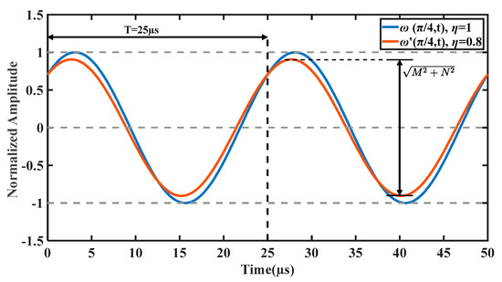
Figure 2.
The vibration of particles on the ring stator in two periods.
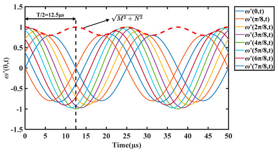
Figure 3.
The vibration of surrounding particles on the ring stator.
It is well-known that the essence of traveling wave operation is the particles on the stator moving in an elliptical trajectory [19,20]. Figure 4 shows the numerical simulation results of motion trajectories of one point on the stator’s surface within several wavelengths , given different values . It can be seen that the motion trajectory of points on the stator surface becomes tilted and irregular when .
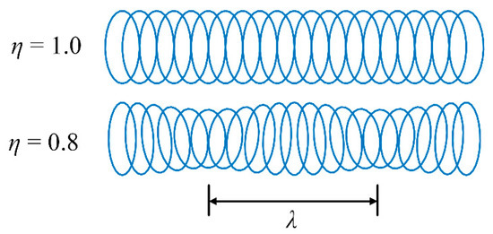
Figure 4.
Motion trajectories of one point on the stator’s surface.
The amplitudes of the traveling wave are different at different instant points, resulting in the unstable operating of TRUSM.
According to the formation of the traveling wave and the elliptical motion trajectory of the stator surface particles, the output characteristics of TRUSMs are directly related to the stator vibration amplitude (SVA) [21,22]. According to the analysis of friction properties and velocity characteristics, the mechanical characteristics of the USM can be simplified by the static friction characteristic in the common operating range [23]. The tangential velocity at the stator surface can be described as a function of several parameters of the USM operating, such as the driving radian frequency , the wavelength of the traveling wave , the half-thickness of the stator , the stator vibration amplitude , the half of contact width between the stator and the rotor , etc. Considering the analysis of friction properties and velocity characteristics, the rotor velocity of TRUSM is directly related to the tangential velocity and can be described as
where is the stator vibration amplitude; is the driving radian frequency; is the wavelength of the traveling wave; is the half-thickness of the stator; and is the half of contact width between the stator and the rotor. As for TRUSM operating in a common range with constant preload, and can be considered constant. Moreover, to maintain high stability and low power consumption, the TRUSMs are suggested to operate at the parallel resonance frequency () [24]. Generally, the frequency band of USMs is much less than the driving frequency. Therefore, the vibration amplitude of the stator determines the rotor velocity of the TRUSM.
Thus, the unstable amplitude of distorted traveling wave can result in unstable rotor velocity. Moreover, all of the standing responses cannot be completely transformed into the traveling wave, and the corresponding mechanical energy will dissipate to reduce the output efficiency of TRUSM.
3. Implementation of the Proposed Scheme
3.1. Hardware Structure
The realization of the proposed scheme is based on the framework of VCBVF. Two transformer ratio-arm bridges without feedback electrodes are used to detect the two-phase SVA.
To establish the relationship between the mechanical vibration amplitude and the electrical variable, the Butterworth–Van Dyke (BVD) equivalent circuit model of the single-phase piezoelectric element of the TRUSM and the schematic diagram of the TRAB are introduced [18,25], as shown in Figure 5. is the static capacitor, , and are the motional resistor, motional capacitor and motional inductor, respectively.
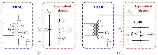
Figure 5.
Electromechanical model of the single-phase piezoelectric element of the USM and TRAB: (a) Equivalent circuit and TRAB; (b) transformation of the electromechanical model and TRAB.
According to the principle of equivalent circuit and Kirchhoff’s law, the stator vibration amplitude can be characterized by the partial voltage , which links the mechanical vibration amplitude and the electrical variable. The stator vibration amplitude can be written as
where is the proportional coefficient and is the voltage of .
To detect the vibration voltage of two-phase, respectively, two transformer ratio-arm bridge circuits with the same structure are used [25]. The transformer ratio-arm bridge consists of a transformer with a tap voltage and a detection capacitor . The two dots (*) are used for indicating the direction of the magnetic coupling between the two coils. According to Kirchhoff’s law, the relationship between the voltage and current in the integrated circuit can be expressed as
where are the turns of the three windings of the transformer.
If the detection capacitor is set as , the relationship between the vibration voltage and transformer tap voltage can be deduced as
Thus, the vibration voltage of the stator can be detected by measuring the transformer tap voltage .
The hardware structure of the proposed scheme is shown in Figure 6, including an STM32 microcontroller, a DC power supply, A and B-phase drive modules, a USM, and an incremental encoder (1000 p/r).
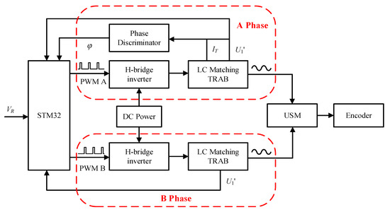
Figure 6.
Hardware architecture of the proposed scheme.
Take phase A as an example: the H-bridge inverter circuit converts the DC voltage into AC voltage output under the control of pulse width modulation (PWM) signals. The amplitude and frequency of output AC voltage are determined by the duty and frequency of PWM signals. The AC voltage is filtered to the sinusoidal voltage by the LC matching circuit and then boosted to the desired driving voltage for the ultrasonic motor. Moreover, the proper amplitude and frequency of driving voltage are adjusted by the microcontroller, according to the control logic and feedback signals. Three feedback signals, excitation current , amplitude voltage signal , and phase difference signal , are detected by the TRAB and phase discriminator. As for phase B, the H-bridge inverter circuit is symmetrical with phase A, while the matching circuit and TRAB are set as the same structure with different matching values. The frequency of phase B signal is adjusted by the A-phase difference and kept the same with A-phase. In addition, an incremental encoder with a resolution of 1000 p/r attached to the USM is used to detect the velocity .
3.2. Control Structure
The control structure of the proposed scheme is shown in Figure 7, including three control loops and four proportional–integral–derivative (PID) controllers: frequency tracking controller, velocity stabilization controller, and two vibration stabilization controllers.
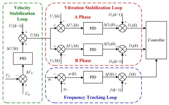
Figure 7.
The control structure of the proposed scheme.
The frequency tracking loop adjusts the output frequency of driving voltages depending on the phase difference between the amplitude voltage and excitation current of A-phase. The target of resonance frequency tracking is to ensure that the ultrasonic motor operates at the parallel resonance frequency point to maintain optimal efficiency and high stability. The PID controller of frequency tracking can be expressed as
where is the increment of the driving frequency; is the phase difference; and , , and are the proportional, integral, and differential coefficients, respectively.
The velocity stabilization loop adjusts the target SVA voltage according to the deviation between the target velocity and the actual velocity. In the velocity stabilization loop, the velocity error, and is the velocity difference between measured velocity and target velocity . The PID controller adjusts the target stator vibration amplitude to keep at 0. The PID controller of velocity stabilization can be expressed as
where is the increment of the target SVA voltage; is the velocity difference between measured velocity and target velocity; and , , and are the proportional, integral, and differential coefficients, respectively.
The vibration stabilization loop with two PID controllers is used to adjust the duty of the PWM signals, according to the deviation between the target stator amplitude and the actual stator amplitude. Two PID controllers are realized separately and simultaneously to compensate for the unbalance in the two-phase driving excitation of the ultrasonic motor in real-time. Taking the A-phase regulation as an example, the PID controller can be expressed as
where is the increment of the duty; is the voltage difference between measured SVA voltage and target SVA voltage ; and , , and are the proportional, integral, and differential coefficients, respectively. The control logic of the B-phase is the same as A-phase, and the compensation for B-phase based on the difference between two-phase is considered.
4. Experimental Results
4.1. Experimental Setup
The proposed scheme is verified and compared with the single-phase SVA velocity control scheme by a USM Shinsei-USR60 and a self-designed experimental platform with unbalanced two-phase matching structure. The specifications of the USM Shinsei-USR60 are listed in Table 1. The experimental setup for TRUSM is shown in Figure 8. The driving and control circuits for the TRUSM are shown in Figure 9. In the experiment, the load torque is provided by a magnetic brake (FKG-10YN; Lanmec electromechanical technology Co., Ltd., Hai’an City, China). An incremental encoder (HEDM-5540-B14; Broadcom Inc., San Jose, CA, USA) is used to detect the velocity. The detected velocity is sent to the microcontroller for real-time control and displayed on the monitor of the laptop. A torque sensor (HCNJ-103; Haibohua Technology Co., Ltd., Beijing, China) with a range of is used to measure the output torque and displays the value via attached instrument.

Table 1.
Specifications of the Shinsei-USR60.
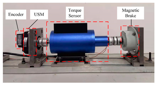
Figure 8.
Experimental setup for TRUSM.
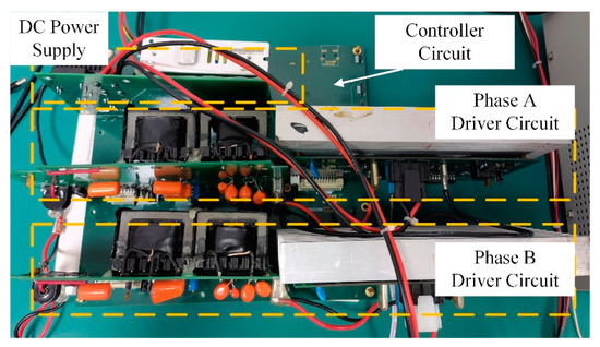
Figure 9.
The self-designed drive and control circuit.
4.2. Verification of the Proposed Scheme
The implementation of the proposed scheme is based on the framework of VCBVF. To verify the performance of velocity control and frequency tracking, the rotor velocity of TRUSM, and the transformer tap voltage , the driving frequency, and phase difference are measured when the velocity increases from 70 rpm to 120 rpm under no-load conditions.
As shown in Figure 10a, the velocity of the TRUSM ranges from 70–120 rpm when ranges from 4.6 V to 7.8 V. When the target velocity of the ultrasonic motor increases from 70 rpm to 120 rpm, the target SVA increases accordingly. Through the duty control of the PWM, the amplitude of the excitation voltage input to the USM also increases accordingly, resulting in an increase in the stator vibration amplitude and the velocity of the motor. The stator vibration amplitude is used as the intermediate control variable, and the fast velocity tracking process of the USM is realized through amplitude detection and voltage adjusting. As shown in Figure 10b, the parallel resonance frequency point shifts due to the change in operating state. The velocity increase is essentially caused by the increase in the stator vibration amplitude, and the increase in SVA causes the stator coupling stiffness to decrease, resulting in the drop of the parallel resonance frequency [26]. As expected, the operating state is quickly adjusted to track the “new” resonance frequency by the frequency tracking loop within 3 ms according to the phase difference. Therefore, velocity control and frequency tracking can be realized with the proposed scheme with high efficiency and reliability.
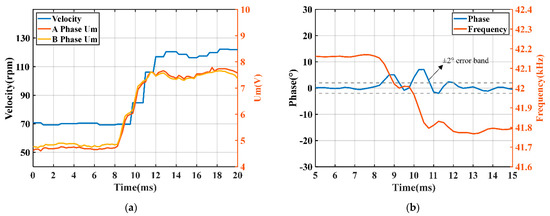
Figure 10.
Verification of the proposed scheme: (a) velocity and vibration stabilization process; (b) frequency tracking process.
4.3. Stator Vibration Amplitude Analyses
To compare the SVA difference between the single-phase feedback VCBVF scheme and the proposed scheme, the two-phase transformer tap voltage at different velocities is measured under the two control schemes without load (as shown in Figure 11). The driving frequency is tracked at the parallel resonance frequency point . The velocity of the TRUSM ranges from 70 to 120 rpm.
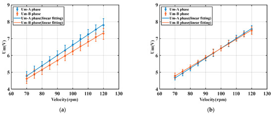
Figure 11.
Stator vibration amplitude analyses: (a) relationship between velocity and SVA voltage in single-phase feedback VCBVF scheme; (b) relationship between velocity and SVA voltage in the proposed scheme.
It can be seen from Figure 11 that the two-phase transformer tap voltages increase proportionally with increasing velocity. Under the two schemes, the tap voltages are almost linear to the velocity, i.e., the stator vibration amplitude is linearly related to the rotational velocity. However, it should be noticed that the relationships between voltage and velocity of two-phase are not consistent in the single-phase feedback VCBVF scheme. Due to the difference between two-phase voltages, a larger vibration amplitude in phase A is required to achieve the same velocity in the single-phase feedback VCBVF scheme. As for the proposed scheme, the amplitudes of the two-phase excitation voltages are adjusted individually and simultaneously through the two-phase vibration stabilization loop. The scheme could balance the two-phase from the perspective of drive control and improve the amplitude consistency of the two-phase standing waves (to improve the “purity” of the synthetic traveling wave). Therefore, the proposed scheme can compensate the two-phase electrical inconsistency and prompt the output performance.
4.4. Output Performance Analyses
To further evaluate the control performance of the velocity, the velocity responses of the USM with different control schemes are compared when the velocity changes from 70 to 120 rpm. The experimental results are shown in Figure 12. The loads are set at 0 Nm, 0.1 Nm, 0.2 Nm, and 0.3 Nm, respectively.
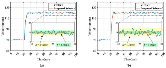
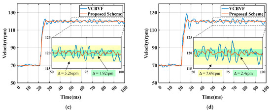
Figure 12.
Velocity responses of the USM with different control schemes: (a) 0 Nm; (b) 0.1 Nm; (c) 0.2 Nm; and (d) 0.3 Nm.
As shown in Figure 12, both velocity control schemes can track the target velocity under variable load conditions. In the case of different loads, compared with the single-phase feedback VCBVF scheme, the proposed scheme reduces the velocity fluctuations and overshoot to different degrees. Figure 12 and Table 2 show that when the load torque for the TRUSM changes from 0 Nm to 0.3 Nm, the overshoot of the proposed scheme increases from 0.96% to 6.90% and velocity fluctuations increase from 1.68 rpm to 2.40 rpm, while the overshoot of the single-phase feedback VCBVF scheme increases from 1.92% to 17.50% and velocity fluctuations increase from 2.62 rpm to 7.69 rpm. This proves that the proposed scheme has a smaller steady-state velocity error and better stability, as well as load-adapting ability.

Table 2.
Control performance of the TRUSM.
The mechanical output torque of the USM in two control schemes is measured under different velocities and the comparison of the torque-velocity characteristics is shown in Figure 13. The output power of the motor is calculated as the product of velocity and torque, detected by the attached encoder and torque sensor, respectively.
where (rad/s) is the angular velocity; is the rotor velocity with a unit of rpm; and is the motor torque. The experimental results show that, compared with the single-phase feedback VCBVF control scheme, the proposed scheme has a larger mechanical torque output under the condition of maintaining a certain speed. It can be explained by the analysis in Section 2.2. As for the single-phase feedback VCBVF control scheme, the slight difference between two-phase standing responses results in a distorted traveling wave. The responses cannot be completely transformed into the traveling wave, and the corresponding mechanical energy will dissipate to reduce the output efficiency of TRUSM. Provided with the same power supply, the proposed scheme can improve the max output power of TRUSM compared with the single-phase feedback VCBVF control scheme. Therefore, the proposed scheme can improve the velocity stability of the motor operation and improve the efficiency within a certain range, and is suitable for the velocity control of USM in precise and stable motion applications.
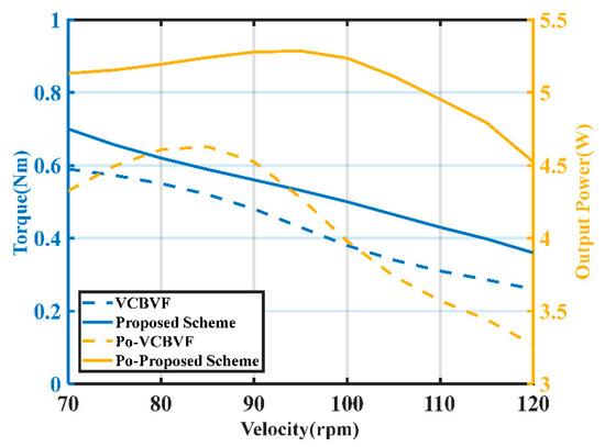
Figure 13.
Comparison of the torque-velocity characteristics with different control schemes.
5. Conclusions
In this paper, a closed-loop velocity control scheme, based on the two-phase stator vibration amplitude of TRUSMs, is proposed. First, based on the structure and operating mechanism of the TRUSM, the influence of two-phase standing wave amplitude difference on stator’s surface particle motion is analyzed. Then, a closed-loop velocity control scheme is proposed, and the specific implementation of the scheme including the hardware and control structure is introduced. Finally, the proposed scheme is verified and compared with the single-phase feedback VCBVF control scheme by a USM Shinsei-USR60. Experimental results show that the proposed scheme can compensate the two-phase inconsistency from an electrical point of view. The proposed scheme can not only improve the velocity stability of the motor operation, but also improve the output power and torque-velocity characteristics. The proposed scheme is an effective supplement to the original control scheme, and can be applied to the velocity control of USM in variable conditions, especially in precise and stable motion applications.
Due to the complex of nonlinearity of the USM, the control strategy is actually approximately simplified. In the future, the friction properties and models considering the difference between two-phase excitation will be investigated in depth, and a control method considering more accurate friction models could be further investigated.
Author Contributions
Conceptualization, X.G. and M.Y.; methodology, X.G. and Y.Z.; software, X.G. and Y.Z.; validation, Y.Z. and Y.H.; writing—original draft preparation, X.G.; writing—review and editing, M.Y. and Y.Z.; visualization, X.G.; supervision, Y.Z. and M.Y.; project administration, M.Y.; funding acquisition, M.Y. All authors have read and agreed to the published version of the manuscript.
Funding
This research was funded by National Natural Science Foundation of China, grant number 32171357.
Institutional Review Board Statement
Not applicable.
Informed Consent Statement
Not applicable.
Data Availability Statement
Not applicable.
Conflicts of Interest
The authors declare no conflict of interest.
References
- Zhao, C.S. Ultrasonic Motors: Technologies and Applications; Science Press Beijing: Beijing, China, 2011; pp. 1–494. [Google Scholar]
- Jia, B.T.; Wang, L.; Wang, R.F.; Jin, J.M.; Zhao, Z.H.; Wu, D.W. A novel traveling wave piezoelectric actuated wheeled robot: Design, theoretical analysis, and experimental investigation. Smart Mater. Struct. 2021, 30, 035016. [Google Scholar] [CrossRef]
- Ryndzionek, R.; Sienkiewicz, L. A review of recent advances in the single- and multi-degree-of-freedom ultrasonic piezoelectric motors. Ultrasonics 2021, 116, 106471. [Google Scholar] [CrossRef] [PubMed]
- Feng, Z.; Liang, W.Y.; Ling, J.; Xiao, X.H.; Tan, K.K.; Lee, T.H. Integral terminal sliding-mode-based adaptive integral backstepping control for precision motion of a piezoelectric ultrasonic motor. Mech. Syst. Signal Process. 2020, 144, 106856. [Google Scholar] [CrossRef]
- Tan, K.K.; Liang, W.Y.; Huang, S.; Pham, L.P.; Chen, S.; Gan, C.W.; Lim, H.Y. Precision Control of Piezoelectric Ultrasonic Motor for Myringotomy with Tube Insertion. J. Dyn. Syst. Meas. Control 2015, 137, 064504. [Google Scholar]
- Zhang, X.F.; Zhang, G.B.; Nakamura, K.; Ueha, S. A robot finger joint driven by hybrid multi-DOF piezoelectric ultrasonic motor. Sens. Actuators A Phys. 2011, 169, 206–210. [Google Scholar] [CrossRef]
- Delibas, B.; Koc, B.; Thielager, J.; Stiebel, C. A novel drive and control method for piezoelectric motors in microscopy stages. In Proceedings of the Euspen’s 21st International Conference & Exhibition, Copenhagen, Denmark, 7–10 June 2021. [Google Scholar]
- Tian, X.Q.; Liu, Y.X.; Deng, J.; Wang, L.; Chen, W.S. A review on piezoelectric ultrasonic motors for the past decade: Classification, operating principle, performance, and future work perspectives. Sens. Actuators A Phys. 2020, 306, 111971. [Google Scholar] [CrossRef]
- Liang, W.Y.; Tan, K.K.; Huang, S.N.; Pham, L.P.; Lim, H.Y.; Gan, C.W. Control of a 2-DOF ultrasonic piezomotor stage for grommet insertion. Mechatronics 2013, 23, 1005–1013. [Google Scholar] [CrossRef]
- Zhang, J.-T.; Zhu, H.; Zhao, C.-S. Modal frequency modification of ultrasonic motor stator. Opt. Precis. Eng. 2008, 16, 2406–2413. [Google Scholar]
- Wang, J.; Jin, J.; Zhao, C. Velocity Stability Research of Traveling Wave Type Rotary Ultrasonic Motor. Proc. CSEE 2011, 31, 109–116. [Google Scholar]
- Yang, L.; Ma, C.C.; Ren, W.H.; Zhang, J.J. Beat traveling wave principle and its verification on rotating ultrasonic motor. J. Vib. Control 2021, 27, 2354–2367. [Google Scholar] [CrossRef]
- Sun, H.X.; Jing, K.; Li, G.Q.; Dong, X. An Optimized Operation Method of Two-Phase Coordinated Control for TRUM Based on the Observer of Vibration Mode. Small Spec. Electr. Mach. 2016, 44, 78–81. [Google Scholar]
- Kuhne, M.; Rochin, R.G.; Cos, R.S.; Astorga, G.J.R.; Peer, A. Modeling and Two-Input Sliding Mode Control of Rotary Traveling Wave Ultrasonic Motors. IEEE Trans. Ind. Electron. 2018, 65, 7149–7159. [Google Scholar] [CrossRef]
- Chen, N.; Jiao, X.K.; Tan, R.Y.; Zheng, J.J.; Fan, S.X. A multi-parameter speed control model of traveling wave ultrasonic motor. Int. J. Appl. Electrom. 2020, 64, 457–464. [Google Scholar] [CrossRef]
- Kebbab, F.Z.; Belkhiat, D.E.C.; Jabri, D.; Belkhiat, S. Frequency Speed Control of Rotary Travelling Wave Ultrasonic Motor Using Fuzzy Controller. Eng. Technol. Appl. Sci. 2018, 8, 3276–3281. [Google Scholar] [CrossRef]
- Lu, S.; Shi, J.Z. Nonlinear Hammerstein model of ultrasonic motor for position control using differential evolution algorithm. Ultrasonics 2019, 94, 20–27. [Google Scholar] [CrossRef]
- Fang, Z.W.; Yang, T.Y.; Zhu, Y.F.; Li, S.Y.; Yang, M. Velocity Control of Traveling-Wave Ultrasonic Motors Based on Stator Vibration Amplitude. Sensors 2019, 19, 5326. [Google Scholar] [CrossRef] [PubMed]
- Chen, H.C.; Han, W.; Qiu, J.H. Investigation on the traveling wave and three-dimensional trajectory of motion on the stator of rotational ultrasonic motors. Int. J. Appl. Electrom. 2020, 64, 631–638. [Google Scholar] [CrossRef]
- Mashimo, T.; Terashima, K. Experimental Verification of Elliptical Motion Model in Traveling Wave Ultrasonic Motors. IEEE Trans. Ind. Electron. 2015, 20, 2699–2707. [Google Scholar] [CrossRef]
- Li, S.Y.; Li, D.Y.; Yang, M.; Cao, W.W. Parameters identification and contact analysis of traveling wave ultrasonic motor based on measured force and feedback voltage. Sens. Actuators A Phys. 2018, 284, 201–208. [Google Scholar] [CrossRef]
- Ben Messaoud, W.; Giraud, F.; Lemaire-Semail, B.; Amberg, M.; Bueno, M.A. Amplitude Control of an Ultrasonic Vibration for a Tactile Stimulator. IEEE Trans. Ind. Electron. 2016, 21, 1692–1701. [Google Scholar] [CrossRef]
- Zhu, Y.F.; Yang, T.Y.; Fang, Z.W.; Li, S.Y.; Lu, C.Y.; Yang, M. Contact modeling for control design of traveling wave ultrasonic motors. Sens. Actuators A Phys. 2020, 310, 112037. [Google Scholar] [CrossRef]
- Zhuang, Y.; Ural, S.O.; Rajapurkar, A.; Tuncdemir, S.; Amin, A.; Uchino, K. Derivation of Piezoelectric Losses from Admittance Spectra. Jpn. J. Appl. Phys. 2009, 48, 056509. [Google Scholar] [CrossRef]
- Yang, T.Y.; Zhu, Y.F.; Fang, Z.W.; Wu, H.Y.; Jiang, W.L.; Yang, M. A Driving and Control Scheme of High Power Piezoelectric Systems over a Wide Operating Range. Sensors 2020, 20, 4401. [Google Scholar] [CrossRef]
- Giraud, F.; Lemaire-Semail, B. Causal modeling and identification of a travelling wave ultrasonic motor. Eur. Phys. J.-Appl. Phys. 2003, 21, 151–159. [Google Scholar] [CrossRef]
Publisher’s Note: MDPI stays neutral with regard to jurisdictional claims in published maps and institutional affiliations. |
© 2022 by the authors. Licensee MDPI, Basel, Switzerland. This article is an open access article distributed under the terms and conditions of the Creative Commons Attribution (CC BY) license (https://creativecommons.org/licenses/by/4.0/).