Article

Study on Multidegree-of-Freedom Ultrasonic Motor Using Vibration Mode Rotation of Metal Spherical Stator

1
Graduate School of Engineering, Muroran Institute of Technology, 27-1, Mizumoto, Muroran 050-8585, Hokkaido, Japan
2
Faculty of Engineering, Department of Information and Communication Engineering, Tohoku Institute of Technology, Sendai 982-8577, Miyagi, Japan
*
Author to whom correspondence should be addressed.
Actuators 2022, 11(1), 27; https://doi.org/10.3390/act11010027
Submission received: 1 December 2021 / Revised: 7 January 2022 / Accepted: 14 January 2022 / Published: 17 January 2022
(This article belongs to the Special Issue Piezoelectric Actuators and Ultrasonic Motors: Future Perspectives)

Abstract

:
Most of the multidegree-of-freedom ultrasonic motors (MDOF-USMs) use a spherical rotor, and the design of the stator is restricted due to the use of the resonance mode. (1) Therefore, there is almost impossible to freely design the overall shape, resulting in a complicated structure. (2) To solve such an inconvenience, an MDOF-USM using a metal spherical stator was proposed. The vibration mode rotation on the stator was designed by theoretical analysis of spherical vibration and finite element method analysis. Multilayer piezoelectric actuators (MPAs) were embedded in the sphere to excite the vibration mode. Cylindrical projections were attached to the surface of the stator to magnify the vibration displacement and worked as the driving part. Their effects were evaluated using an electronic circuit simulator method of performance analysis. (3) As a result, two types of vibration mode rotation methods for the 3-DOF rotation were confirmed. It was also confirmed that the rotor covering the outside stator rotates around three axes. However, tiny torque, low power factor, and slow speed were obtained. (4) An MDOF-USM using a spherical stator was realized according to the operating principle. However, since the cause of such a low performance is the excitation method of the sphere and the rotor structure, research for improvement is required in the future.

1. Introduction

An actuator system that realizes multi-degree of freedom (MDOF) movements by a single device has been needed [1,2]. An MDOF system can be easily realized by combining a single-degree of freedom (1-DOF) motor. However, such a system tends to be large, heavy, and slightly complicated in control and structure, so assembly errors are a concern. Therefore, MDOF actuators based on various principles have been researched. Especially, the electromagnetic type and the piezoelectric type of an MDOF actuator have been studied actively. MDOF electromagnetic motors (EMMs) have been realized using a principle similar to the operating principle of single-axis EMMs by all the operating principles of single-axis EMMs. For example, DC servo motor type [3], synchronous type [4], induction type [5], permanent magnet (PM) stepping type [6], and PM synchronous types [7,8], outer rotor type [9]. Depending on the application, the electromagnetic-type MDOF actuator may require a decelerator due to its low torque characteristic at high speeds. Such the MDOF actuator system becomes complicated. In contrast, the piezoelectric-type MDOF actuators, including the MDOF ultrasonic motor (USM), are expected to have advantages of the 1-DOF type USM, such as high torque at a low speed, a self-holding force without electric power, and noiseless due to a nonmagnetic operating principle [10]. Therefore, the MDOF-USM is expected to be applied to humanoid robot’s joints [11,12], spacecraft [13,14], and medical devices [15], i.e., fields where a compact multi-DOF actuator system is required. Some types of the MDOF-USM have been reported: the spherical USM using three-ring stators which generate a traveling wave of bending mode [16], a rod-type MDOF-USM using the degenerate mode of longitudinal vibration and bending vibration of cylindrical stator [17,18,19], an annular disk type MDOF-USM using multiple vibration modes of annular disk stator and its sandwich-type [20,21], a micro MDOF-USM [22,23], and other unique types [24,25,26]. Most of the reported MDOF-USMs have the disadvantage of smaller torque and output power than the 1-DOF type. One of the reasons may be that the effective contact area between the rotor or slider and the stator becomes smaller in principle. However, an MDOF-USM with relatively high torque has also been achieved [27]. However, the designs of structure and vibration mode of stators of those MDOF-USMs are complicated. These MDOF-USMs have a typical structure that rotates a sphere as a rotor. In general, the stators of MDOF-USMs have strict shape conditions due to the resonance mode design. Therefore, as long as the rotor is spherical, there is almost no degree of freedom in designing the overall shape. In other words, there are many design restrictions. Therefore, it is desirable to devise MDOF-USM, which has a high degree of freedom in structural design.
The purpose of this study is to experimentally examine the possibility of MDOF-USM using a metal spherical stator as part of the study to expand the design freedom of MDOF-USM. There is a possibility that the limitation of the axis of rotation can be removed in principle. The MDOF-USM using a metal spherical stator was dealt with in this paper. The authors have proposed and realized the excitation and support of the spherical stator in the case of 1-DOF in previous research [28]. The MDOF-USM using a piezoelectric ceramic spherical-shell stator with a spherical rotor has been developed [29]. The in-plane non-axisymmetric mode of the spherical shell has been utilized for this MDOF-USM, and the method of realizing the spherical stator is different from ours. There are still few studies on USM using spherical stators, and this study seems to be of academic and engineering significance. This MDOF-USM using a spherical stator is expected to be applied to the joint mechanism of humanoid robots and others. This type of MDOF-USM has two significant advantages: (1) it is easy to design the vibration mode of a stator. In other words, ideally, since the vibration mode of the sphere can be excited innumerably just by changing the axis of symmetry, it is possible to easily realize the same rotation as the traveling-type USM by combining the vibration modes of the same shape and innumerable rotation axes can be configured; (2) the shape of a rotor can be designed more freely, and more materials can be selected.
The excitation method and support method of the 1-DOF spherical stator were devised in previous research [28]. Multilayered piezoelectric actuators (MPAs) were embedded in a sphere to excite vibration. In this paper, we expand the 1-DOF spherical stator to 3-DOF. The vibration analysis of the spherical stator was performed using the equation of motion and finite element analysis (FEA, COMSOL Multiphysics 5.2). We consider two types of vibration mode rotation and the rotor driving method using cylindrical projections (driving part) attached to the surface of the spherical stator. The dimension of these driving projections is determined by FEA, and the effect of rotary force generation is evaluated by analysis technique using the electromechanical equivalent circuit designed in an electric circuit simulator [30]. Furthermore, from experiments of the prototype MDOF-USM using the spherical stator, the vibration mode rotation and rotor rotation characteristics are confirmed.

2. Operating Principle

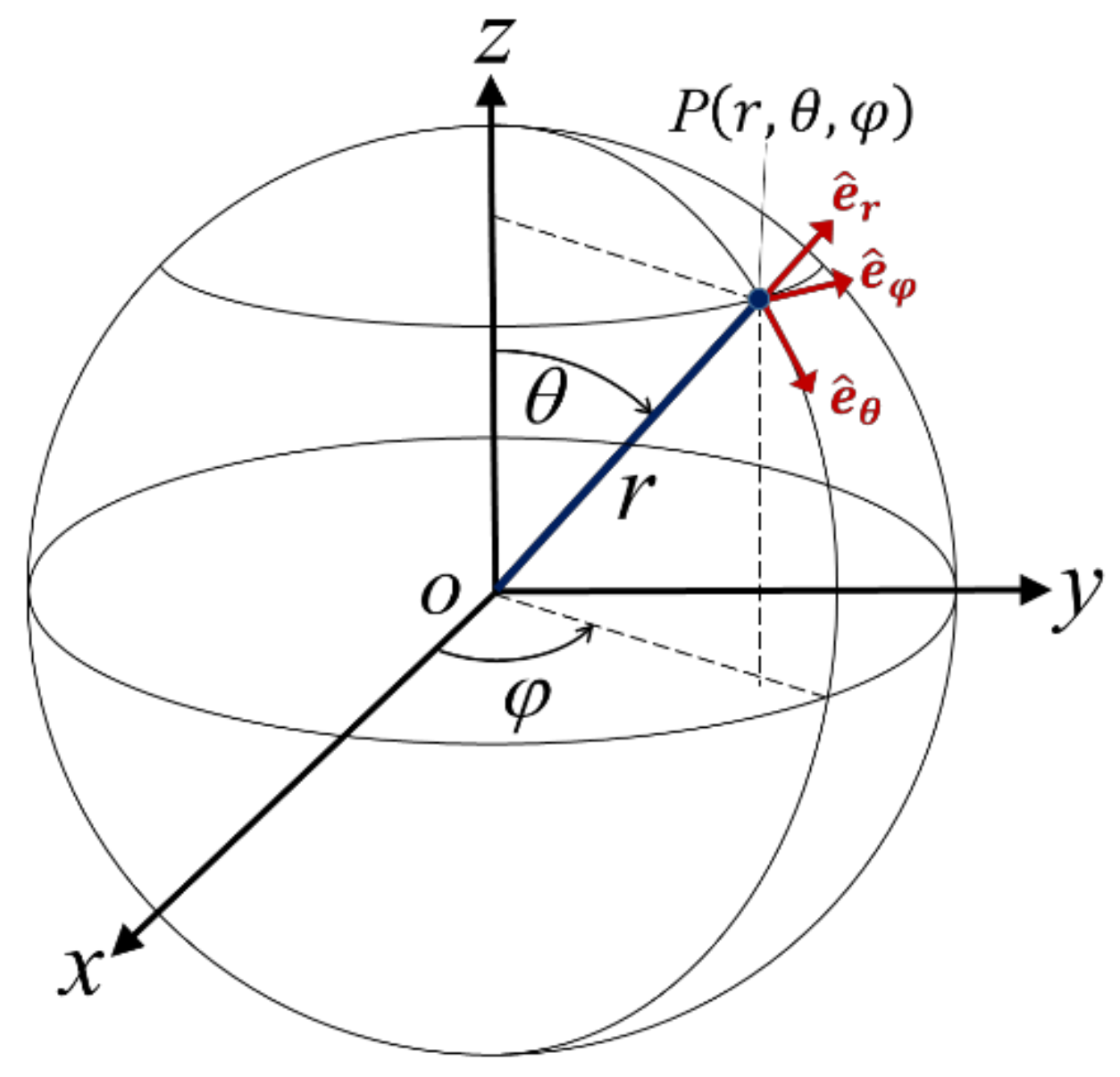
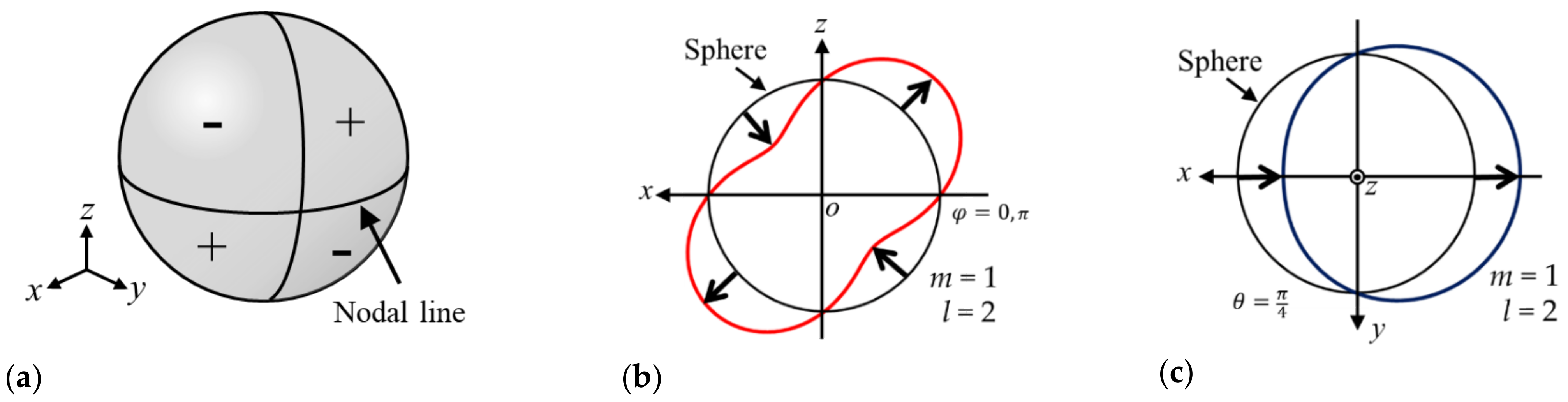
2.1. Natural Vibration Mode of a Sphere

Consider the search for the natural vibration modes of a sphere suitable for a spherical stator used in the MDOF-USM. The coordinate system is given in Figure 1.
The equation of motion of an isotropic homogeneous elastic medium is expressed as
ρ 2 u t 2 = λ + μ · u + μ 2 u , = e ^ r r + e ^ θ 1 r θ + e ^ φ 1 r sin θ φ ,
where e ^ r ,   e ^ θ , e ^ φ represent unit vectors in each of the coordinate directionsas shown in Figure 1, u = u r ,   u θ , u φ is the displacement vector at point P, ρ is the density, and λ and μ are the so-called Lamé parameters describing the elastic properties of the medium. u can be decomposed by Helmholtz decomposition as
u = U + × A ,
where the scalar potential U and the vector potential   A . The first term represents a curl-free component and is denoted by u 1 . The second term represents a divergence-free component and expresses the shear displacement of the torsional vibration mode and other share modes. In this paper, we mainly focus on the spheroidal mode with expansion and contraction of a sphere and exclude the shear vibration mode, in which no volume deformation occurs. Therefore, only u 1 = U is considered. In this case, Equation (1) becomes
2 t 2 U = λ + 2 μ ρ 2 U .
Assuming that the angular frequency is ω and the displacement changes in the form of exp i ω t , by separating the time components, the Helmholtz equation is obtained as
2 U = k 2 U ,
where
k = ω c , c = λ + 2 μ ρ .
Equation (4) is expressed in spherical coordinates as
1 r 2 r r 2 U r + 1 r 2 sin θ θ sin θ U θ + 1 r 2 sin 2 θ 2 U φ 2 = k 2 U .
The solution of Equation (6) is given by separation of variables:
U r ,   θ ,   φ = R r Θ θ Φ φ .
In general, the natural vibration mode of the free vibration of the anisotropic elastic sphere can be obtained by giving the boundary condition that the stress at the surface of the sphere is zero. However, the radial function R r does not express the shape of the natural vibration mode. The angle functions Θ θ and Φ φ are combined into a single function called the spherical harmonics Y l m θ , φ   defined by [31,32]
Y l m θ ,   φ = 2 l + 1 4 π l m ! l + m ! P l m cos θ e i m φ ,
where P l m cos θ is the associated Legendre function; l, a positive integer; and m, a positive integer or negative one. There is the relationship of |m| ≤ l.
The spherical harmonics can be visualized as an approximate shape of the natural vibration mode of a sphere by nodal lines corresponding to lines of latitude and longitude of the earth. l, m, and lm indicate the total number of nodal lines, the number of longitude lines, and the number of latitudes, respectively. By visualizing the real part of the spherical harmonic function, we searched for the vibration modes suitable for the stator of MDOF-USM. For l = 2 and m = +1, the real part of Equation (8) is
Re Y 2 1 θ ,   φ = 3 2 5 24 π sin 2 θ cos φ = U 0 sin 2 θ cos φ .
Figure 2a visualizes the sign and zero value of the phase in Equation (9) on a sphere. It can be seen that there is one line each corresponding to the latitude and longitudinal line. They appear by sin 2 θ and cos φ in Equation (9), respectively. In addition, to make the vibration modes easier to understand, Figure 2b shows the deformations in the x-z plane created from Equation (9). This figure is similar to the displacement diagram of the non-axisymmetric vibration mode ((2, 1)) or ((2, 2)) of a disk [33]. Similarly, Figure 2c shows the deformations in the plane perpendicular to the z-axis and is similar to the displacement diagram of the non-axisymmetric vibration mode ((1, 1)) of a disk. These suggested that a modal rotation type MDOF-USM could be realized when combined with the same shape orthogonal modes [33]. Hence, the vibration modes with l = 2 and m = +1 were selected in this study. Figure 3a,b show vibration mode diagrams obtained by eigenmode analysis of the sphere of arbitrary diameter with FEA. These modes are degenerate and orthogonal to each other, called l2m1-mode and l2m1′-mode (see Supplementary Materials), respectively [28]. Figure 3a corresponds to Figure 2b,c. This vibration mode is shaped like a rugby ball, but the displacement in the y-axis is zero.

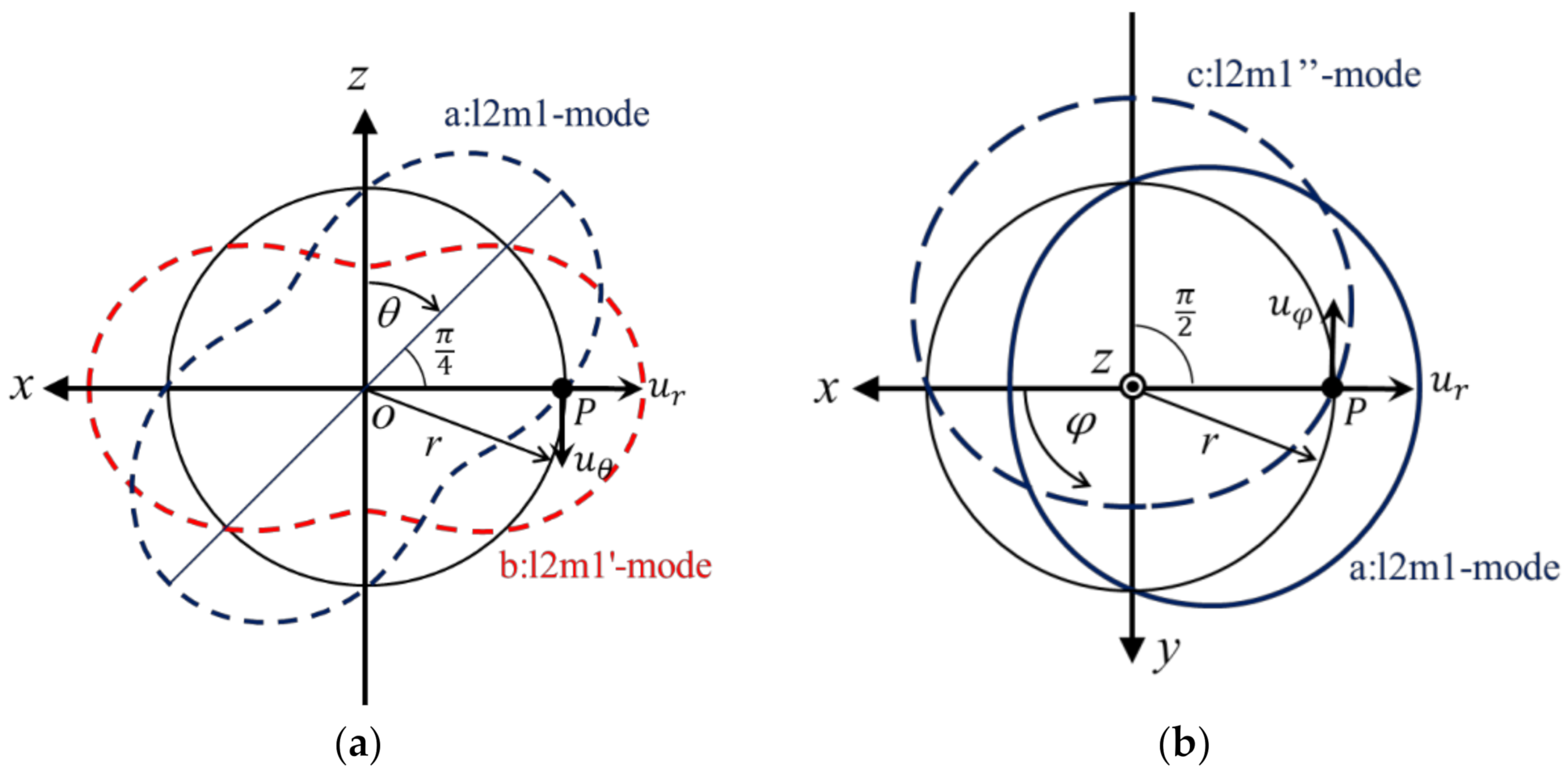
2.2. Vibration Mode Rotation

Figure 4a,b show images of vibration mode rotations of Type-A and Type-B, respectively.
In the case of Type-A, the vibration mode rotation is generated by providing a time phase difference of 90° to the excitation of degenerate modes l2m1-mode and l2m1′-mode. The combined displacement components u r and u θ are obtained from the two degenerate modes a:l2m1-mode and b:l2m1′-mode in Figure 5a as
(a: l2m1-mode)
u r a = U r sin 2 θ cos φ · sin ω t u θ a = U θ cos 2 θ cos φ · sin ω t
(b: l2m1′-mode)
u r b = U r sin 2 θ π / 2 cos φ · cos ω t u θ b = U θ cos 2 θ π / 2 cos φ · cos ω t ,
where
U r = U 0 d d r j l k r U θ = 2 U 0 j l k r r
and j l k r is a spherical Bessel function.
Hence
u r = u r a + u r b = U r cos 2 θ + ω t cos φ u θ = u θ a + u θ b = U θ sin 2 θ + ω t cos φ u r U r cos φ 2 + u θ U θ cos φ 2 = 1 ,
where φ π / 2 , 3 π / 2 , i.e., except on the y-axis. Equation (13) shows that u r and u θ rotate in the θ direction with angular speed θ ˙ = ω / 2 . This means the vibration mode rotation occurs as the l2m1-mode shown in Figure 3a revolves around the y-axis. Moreover, an elliptical motion displacement occurs on the surface of a sphere.
In the case of Type-B, the analysis is performed using Figure 5b in the same way as Type-A. The l2m1″-mode, which is a 90° rotation of l2m1-mode around the z-axis, is used. Giving l2m1-mode and l2m1’-mode a time phase difference of 90° causes vibration mode rotation around the z-axis, such as the precession of 12m1-mode. The combined displacement components u r and u φ are obtained from the two degenerate modes a:l2m1-mode and c:l2m1″-mode in Figure 5b as
(a: l2m1-mode)
u r a = U r sin 2 θ cos φ · sin ω t u φ a = U φ cos θ sin φ · sin ω t
(c: l2m1″-mode)
u r c = U r sin 2 θ cos φ π / 2 · cos ω t u φ c = U φ cos θ sin φ π / 2 · cos ω t
where
U r = U 0 d d r j l k r U φ = 2 U 0 j l k r r .
Hence
u r = u r a + u r c = U r sin 2 θ sin φ + ω t u φ = u φ a + u φ c = U φ cos θ cos φ + ω t u r U r sin 2 θ 2 + u φ U φ cos θ 2 = 1 ,
where θ 0 ,   π / 2 , π , that is, other than the poles and the equator. Equation (17) shows that u r and u φ rotate in the φ direction with angular speed φ ˙ = ω / 2 , and that an elliptical displacement occurs on the surface of the sphere. Therefore, the vibration mode rotation occurs as the l2m1-mode shown in Figure 3a precesses around the z-axis. In other words, a traveling wave generates on the surface of the spherical stator in the same direction. However, the vibration displacement distributes along the longitude line, which is the smallest on the great circle around the axis of vibration mode rotation.
An elliptical displacement occurs at the contact surface between a rotor and the stator when generating vibration mode rotations. The rotor is driven by a frictional force similar to a traveling-wave-type ultrasonic motor. Similarly, the vibration mode rotation can be developed around an arbitrary axis by switching excitation points, and the MDOF-USM can be realized.

3. Vibration Analysis

3.1. Stator Construction

It was confirmed that the l2m1-mode and its vibration mode rotation around a single axis could be excited by multilayered piezoelectric actuators (MPAs) embedded in the spherical stator [28]. To expand to 3-axis rotation, 24 MPAs were embedded in the sphere surface, as shown in Figure 6. Each 8 MPAs are used for each axis rotation. 8 MPAs are arranged on the great circle around each axis with the regular interval. The MPA (6 × 6 × 5 mm3) used for the stator consisted of 60 laminated hard material type piezoceramic sheets polarized in the thickness direction and has a capacitance of approximately 350 nF. Table 1 shows the properties of piezoelectric ceramics using MPA. This material has high values in mechanical quality factor Qm, coupling factor K33, but the dielectric dispersion factor is low. The hard material type piezoceramics generally endure a high-frequency drive due to low loss compared to the soft material one. The MPAs were embedded in square holes into a stainless steel SUS304 sphere 50.8 mm in diameter, and those were secured in the hole with metal wedges [28].
FEA carried out the eigenvalue analysis and frequency domain analysis of the simplified stator model. The model used for FEA was created with boundary conditions of the free boundary, tetrahedral mesh, seven divisions in the radial direction, 40 divisions in the circumferential direction, a maximum element size of 8.82 mm, and a minimum element size of 1.65 mm. From these analysis results, the generations of l2m1-mode and l2m1′-mode were confirmed. The 3-axis vibration mode rotations of Type-A and Type-B were obtained by providing a phase difference of 90° to the excitation of the two modes.

3.2. Effect of Driving Projection

There are MPAs, metal wedges, and wirings on the surface of the spherical stator. Therefore, it was difficult to extract a friction force directly from the surface of the stator for rotor driving. The rotor driving by projections attached to the surface, as shown in Figure 7a, was devised. This projection also had the role of expanding the lateral displacement by the principle of the lever. The projection was made of stainless steel (JIS, SUS304) and had a screw thread part fastened into the stator, as shown in Figure 7b. To determine the dimension of the driving projection, the effect of the dimension of the driving projection on the displacement was investigated by the FEA. As a result, the displacement trajectory of the tip of the driving projections varied depending on the dimension. However, when the length of the driving protrusion was around 5 mm, its diameter did not significantly affect the displacement of the spherical stator and driving projections. Therefore, first, the diameter was set to the upper limit of 6 mm, which does not interfere with the arrangement of the MPAs on the stator.
On the other hand, the length L of the driving projection made a difference in elliptical displacement. Figure 8a shows the simulated elliptical displacement of L = 5 mm driving projections. Their rotation directions were indicated by arrows in Figure 8a. Due to the different rotational direction of the elliptical displacement of some of the projections, the L = 5 mm projection was not suitable for driving the rotor. However, when L= 4.5 mm or less, all driving projections’ rotation direction of displacement was uniform. Accordingly, to avoid the critical length of 4.5 mm for the driving projections, L = 4 mm was chosen with a margin. Figure 8b shows the elliptical displacements of L = 4 mm driving projections. Their rotations were in the same direction, although they were a little different in shape and size.

4. Thrust Generation Analysis

We attempted to simulate the maximum thrust generated at each driving projection numbered in Figure 9. This type of MDOF-USM was presumed as the analysis model shown in Figure 10. The MDOF-USM comprises the rotor and the stator expressed by two vibrators arranged at right angles. Each vibrator corresponds to a vertical component and horizontal one of the vibrations at the driving projection. A preload is applied using a spring between the vibrator and rotor. The rotor rotates owing to friction when the stator is in contact with the rotor. The top of the stator, which corresponds to the tip of driving projection here, undergoes nonlinear motion by the contact and separation with the rotor. Such a model can be expressed and analyzed by the electromechanical equivalent circuit [30]. Details are described in Appendix A.
The value of calculated maximum thrust, which may be different from the actual value, is useful to grasp how driving projections contribute to generating rotation force. Table 2 shows the contribution to the rotation of each driving projection to the rotation from the simulation result of the generated maximum thrust. The contribution degree is normalized with the largest value of calculated maximum thrust of the driving projection on each rotation axis, expressed as a percentage. In the case of Type-A, the driving projections farthest from the axis of rotation, which correspond to 1(x) for x-axis rotation and 3(y, z) for z-axis rotation shown in Figure 9, respectively, had the contribution of 100%. In contrast, the driving projection, 1(y, z), on the axis of z-axis rotation had no contribution to the generation of z-axis rotation. However, although the driving projections 3(x) and 3(y, z) were on the axis of x- and y-axis rotations, they also contribute to rotation due to the asymmetry of the driving projection arrangement with the x, y-axis. In the case of Type-B, the driving projections farthest from the axis of rotation, which correspond were 1(x) for x-axis rotation, 1(y, z) for y-axis rotation, and 3(y, z) for z-axis rotation, were no contribution to each rotation generation. The contribution of driving projections, 2(x) and 2(y, z), were the highest for all axis of rotation.

5. Performance Evaluation of MDOF-USM Using Spherical Stator

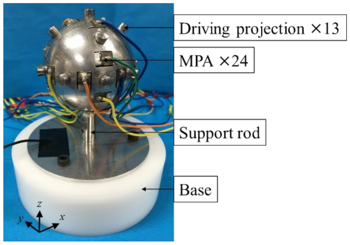
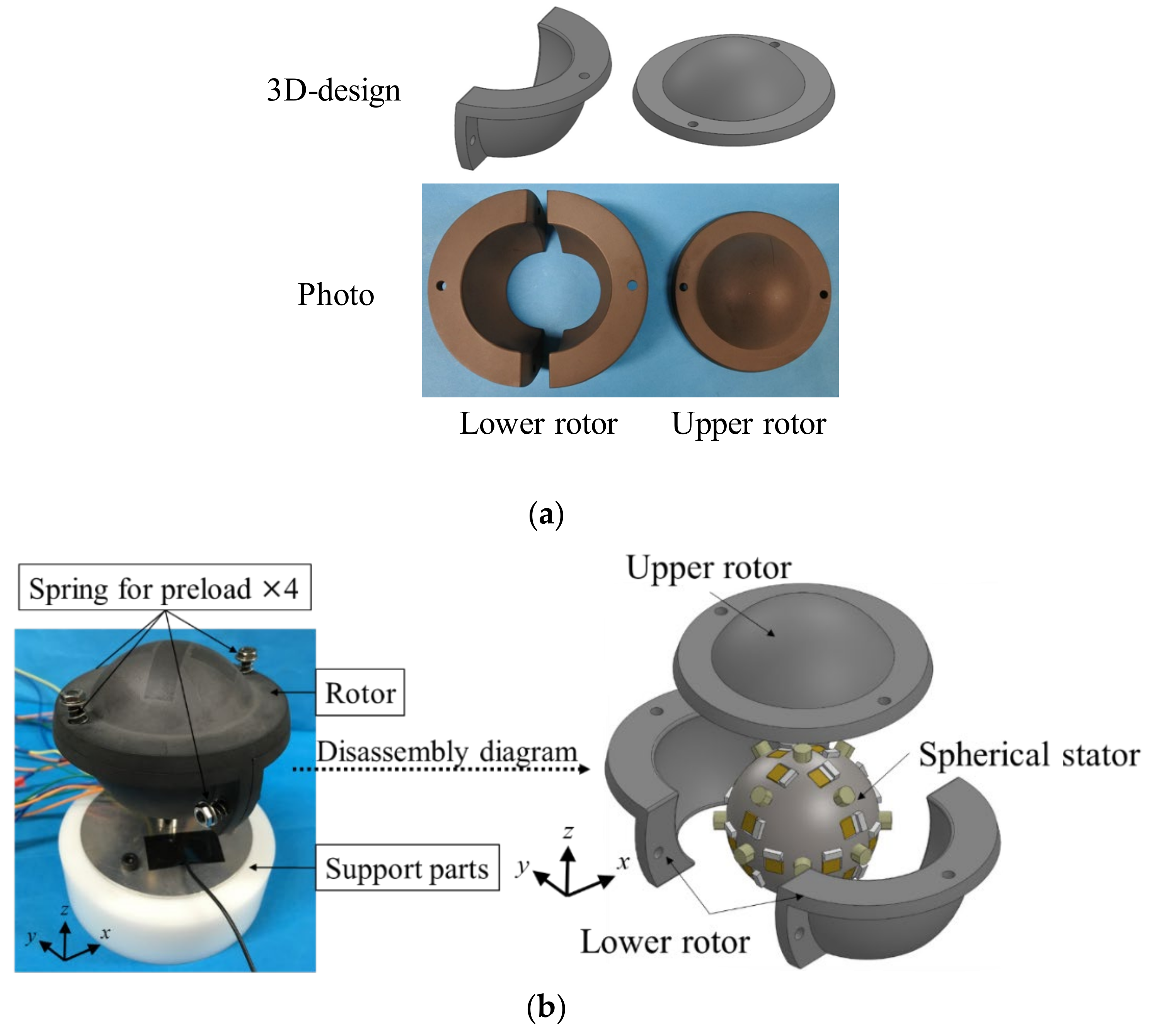
5.1. Construction of Prototype Spherical Stator

The prototype spherical stator was fabricated, as shown in Figure 11. The 24 MPAs were embedded and secured in the hole with metal wedges, and 13 driving projections were attached to the surface of the stator. The tip of each driving projection had a spherical surface for fitting to the rotor. The bottom of the stator was supported by the rod designed to reduce the vibration suppression of the stator [28].
Figure 12 shows the definition of electrical ports exciting each vibration mode and mode rotation. To excite the l2m1-mode or l2m1′-mode, four MPAs per mode were used and constructed an electrical port. The four MPAs were arranged on the circumference of the axial plane of the stator at equal intervals in the case of the spherical coordinate centering at the center of the stator. Port A and Port B shown in Figure 12a, and Port C and Port D shown in Figure 12b, were for x-axis and z-axis rotations by the mode rotation of Type-A, respectively. Port E and Port F were constructed by MPAs arranged in great circles of two different axial planes, as shown in Figure 12c. Those ports were used for x-axis rotation by the mode rotation of Type-B. Port G and Port H shown in Figure 12e were used for x-axis rotation by the mode rotation of Type B. Each electrical port for y-axis rotation by Type-A and Type-B was also defined similarly as x-axis rotation, but it is omitted here because it has the same characteristics as x-axis rotation.
The influence of the support rod on the vibration modes varies with each vibration. There are also cases where the effect is unequal for two vibration modes used simultaneously. Since the support rod is located on the z-axis, the vibration modes with the z-axis as the common symmetry axis are equally affected. Specifically, when z-axis rotation is obtained by Type-A, the effect is equal and minimal. In the case of obtaining z-axis rotation with Type-B, the influence is even but not small. In addition, for x-axis rotation, the effect is expected to be large and uneven. The above is briefly summarized in Table 3. These states were confirmed by measuring the vibration displacement using a laser Doppler vibrometer.

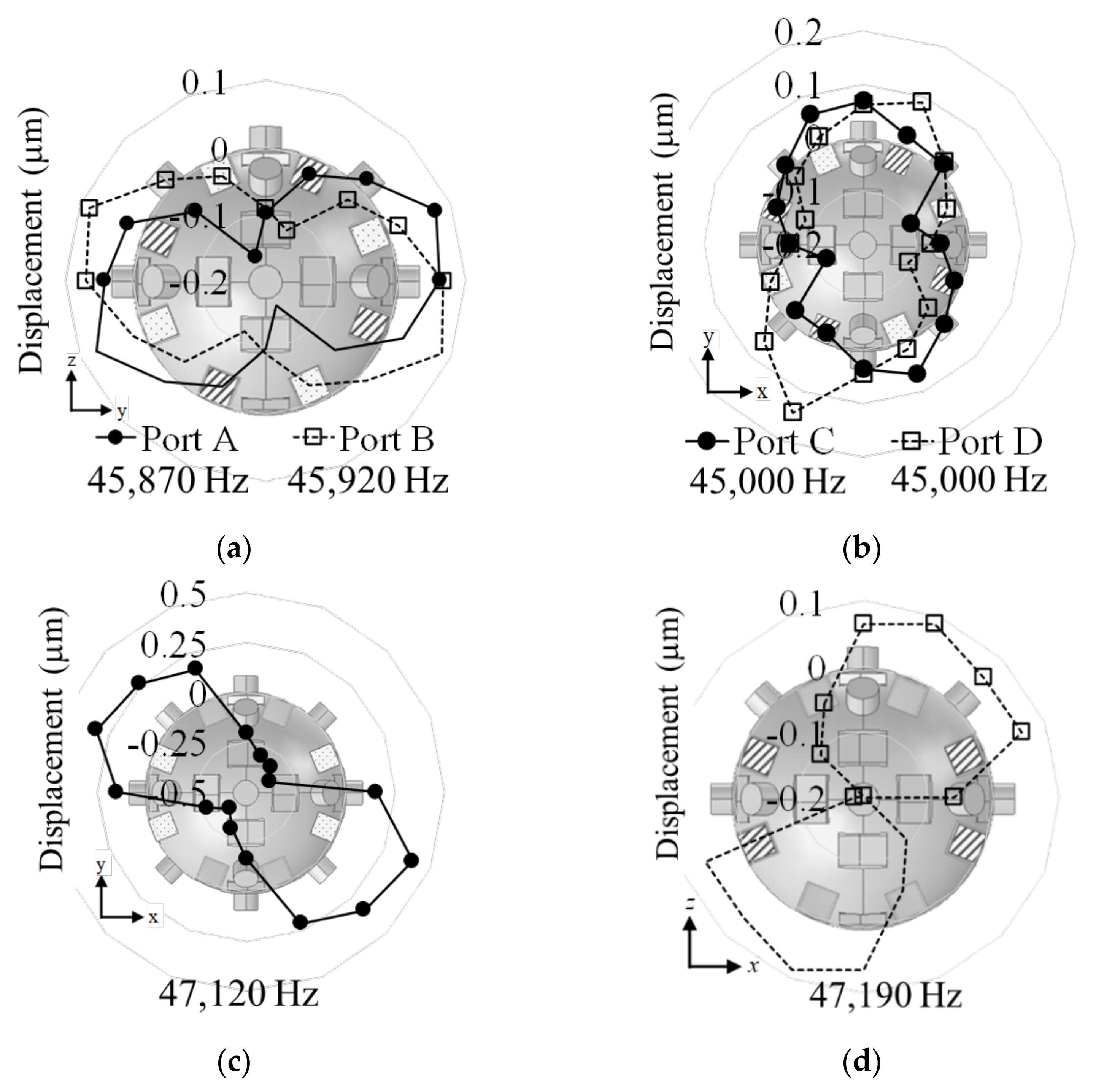
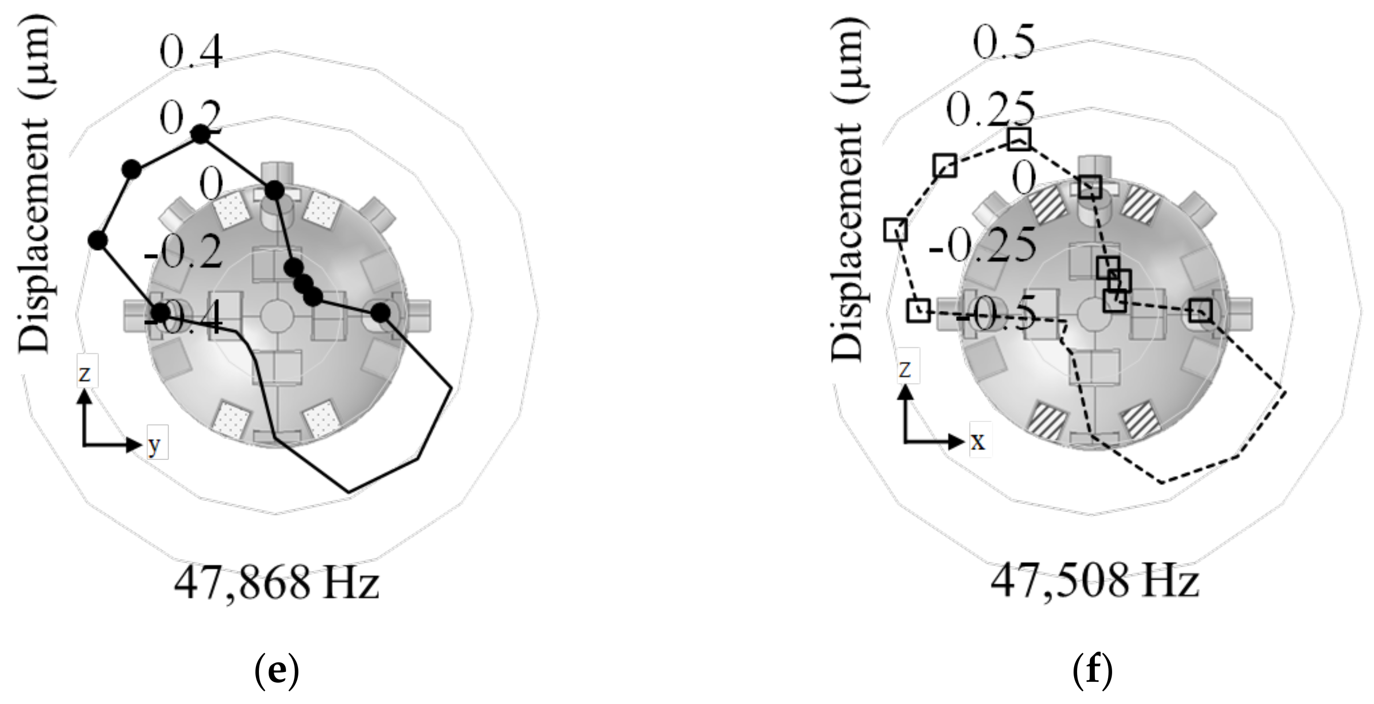
5.2. Displacement Measurement

Figure 13 shows the displacement distributions measured at 30 VP-P (offset 15 V) applied into Port A to Port H. Although there were some differences in amplitude and shape among the measured results, the l2m1-mode and l2m1′-mode excited by each port were confirmed. From these results, when a time phase difference of 90° was given between the ports of each pair, the vibration mode rotation around the three axes of Type-A and that around the z-axis of Type-B were confirmed by the rotation of the ball bearing contact with the surface of the stator. The resonance frequency of each mode was obtained by measuring the frequency-admittance characteristics. The driving frequencies at those times were 45,895 Hz for the x(y)-axis, 45,000 Hz for the z-axis in Type-A, and 47,688 Hz for the z-axis in Type-B. However, we could not confirm the vibration mode rotation of x- and y-axes of Type-B. The cause can be a large difference between the magnitudes of the displacements of two vibration modes. This agreed with what was expected in Table 3 and the previous section. However, although the vibration displacements of the excitations at Port A and Port B were small, they were excited almost evenly, contrary to expectations.
The l2m1-mode excited by Port E was hardly influenced by the support rod connected with the stator on the z-axis. In contrast, the displacement amplitude of the l2m1-mode excited by Port F was easy to become small because the Port F was used for exciting the l2m1-mode of the stator and the bending vibration (B21-mode) of the support rod [28]. The frequency adjustment of the B21-mode of the support rod was inadequate, resulting in a high mechanical impedance and consequently a weak excitation of the l2m1-mode. Therefore, it was difficult to generate the vibration mode rotation around the x(y)-axis of Type-B using the excitation by the combination of Port E and Port F. Hence, the x(y)-axis rotation of Type-A and z-axis rotation of Type-B with large displacements were considered to be suitable for rotor drive.

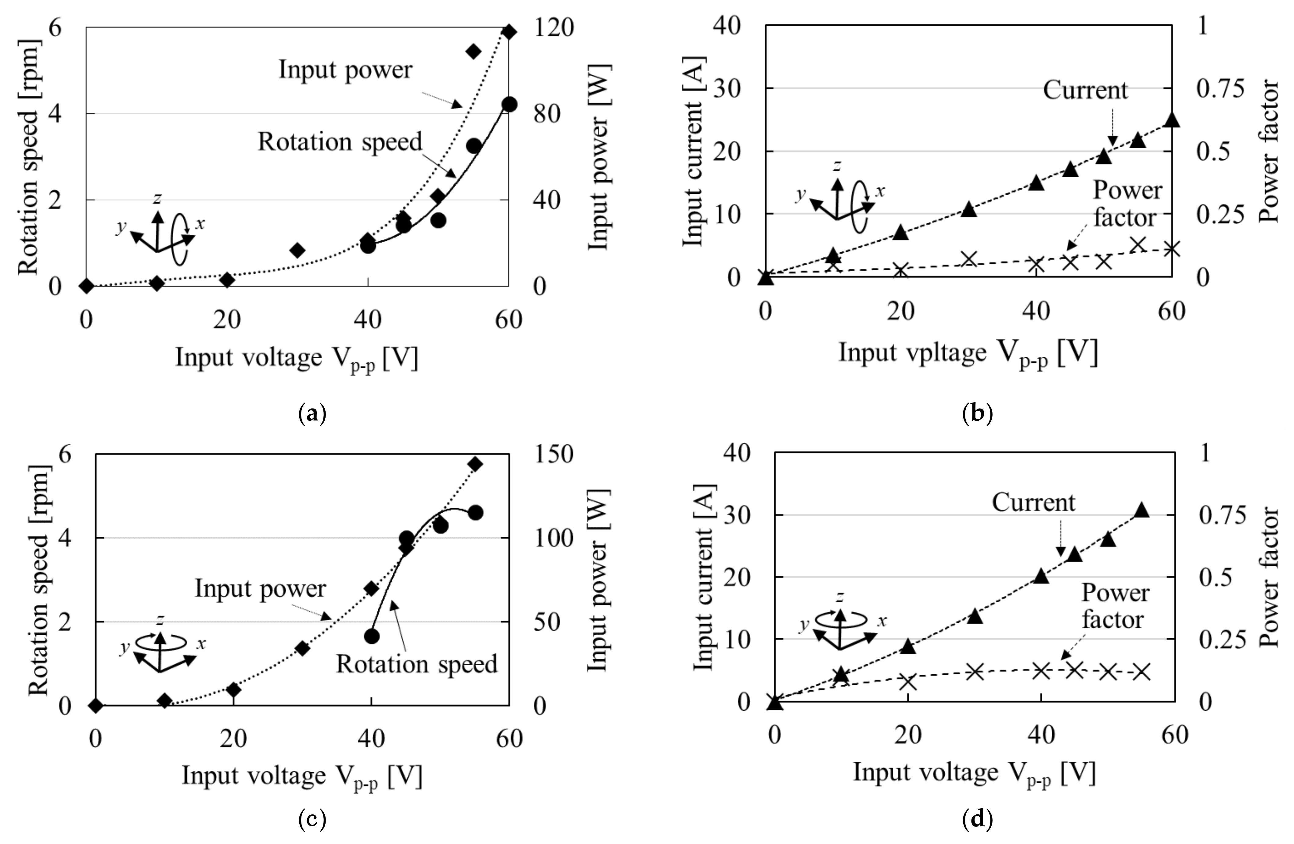
5.3. Characteristic of MDOF-USM Using Spherical Stator

Figure 14a shows the parts of the rotor for the spherical stator. The rotor was made of PPS containing 40% glass fiber, consisting of three pieces of two lower parts and an upper part. The lower parts were linked to each other by two springs. They sandwiched the stator and gave a preload by two springs from the side, as shown in Figure 14b. In addition, the lower parts were linked again with the upper part by springs, and they gave the vertical preload to the stator. This structure enabled the preload adjustment from the plural directions by tuning each spring.
Figure 15 shows the measurement results of the rotation speed of the prototype MDOF-USM using the spherical stator, input power, and power factor during the operation. The preload at this time was set to 0.49 N. The x(y)-axis rotation was generated at 45,750 Hz by Port A and Port B for mode rotation of Type-A, and the z-axis rotation of Type B was generated at 47,587 Hz by Port G and Port H. From these results, the maximum rotation speed on x(y)-axis rotations of 4.23 rpm at 60 VP-P and that on z-axis rotation of 4.62 rpm at 55 VP-P were obtained. The rotor speed was calculated by image processing the video recording data. The output torque was too small to measure. However, much input power was needed for mechanical and dielectric losses of MPAs and large friction loss between the rotor and stator. Hence, the efficiency was infinitely close to zero. The power factor was small for the large capacitance of MPAs. The capacitance of a single MPA was approximately 350 nF, and since eight MPAs were used simultaneously, the total was 2.8 μF. This was a tremendous value and the main reason for the low power factor. In addition, the power factor increased slightly as the current and power increased. This means that the losses increased.
The MDOF-USM using the metal spherical stator was realized first, but its performance must be improved. It will be necessary to improve the power factor with inductors and reduce the input current in the future.

6. Summary and Conclusions

The results are summarized as follows:
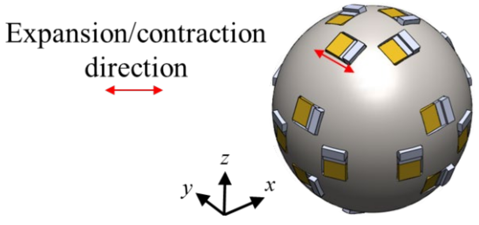
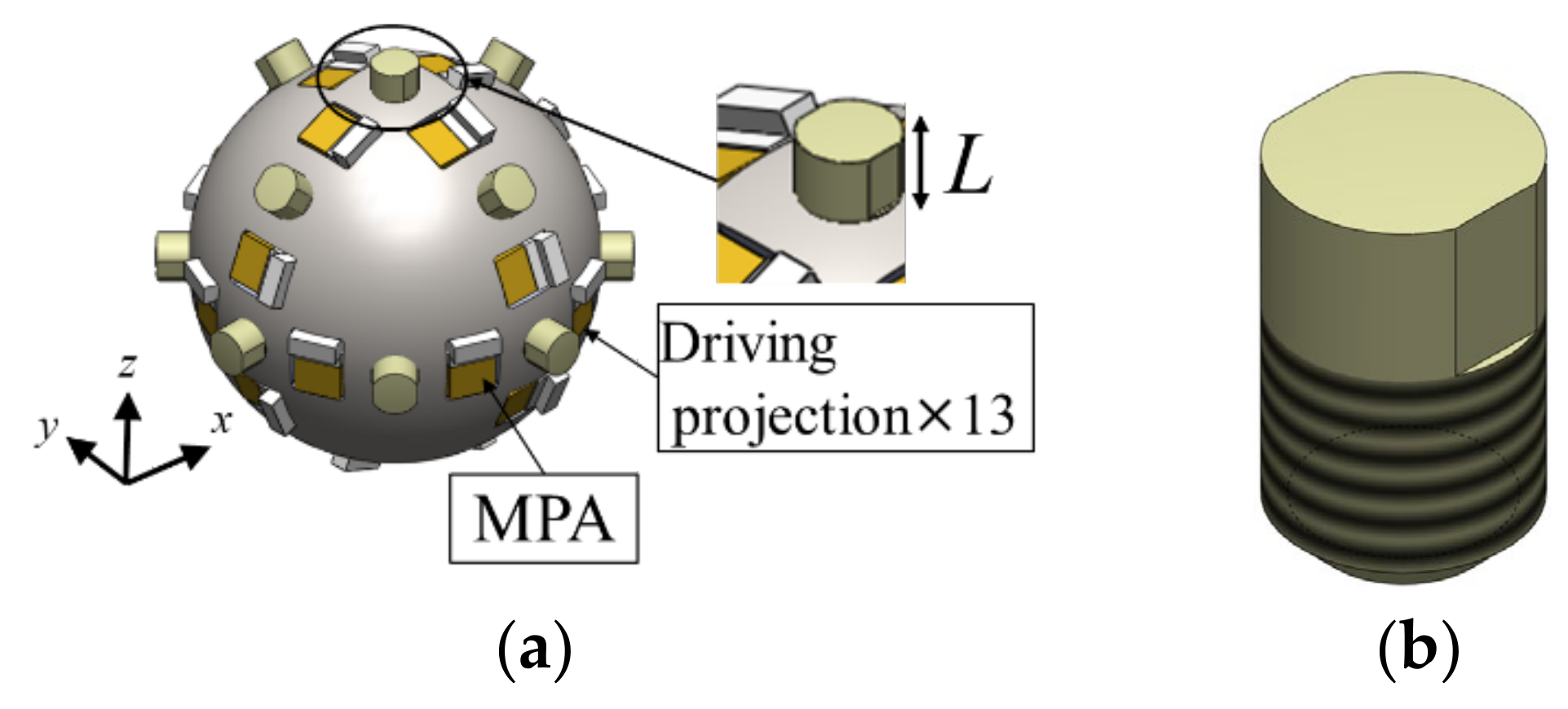
  • The spherical stator extended for 3-DOF rotation was designed. Twenty-four MPAs were embedded on the stator to excite three sets of combinations of l2m1-mode and its orthogonal mode.
  • The surface of the stator could not be used for thrust output by friction force directly because the surface was not smooth with obstacles such as MPAs, their fixture, and their wiring. Hence, projections were arranged as driving parts on the spherical stator to output thrust force. The shape of the driving projection was designed by FEA, and its suitable dimension was clarified.
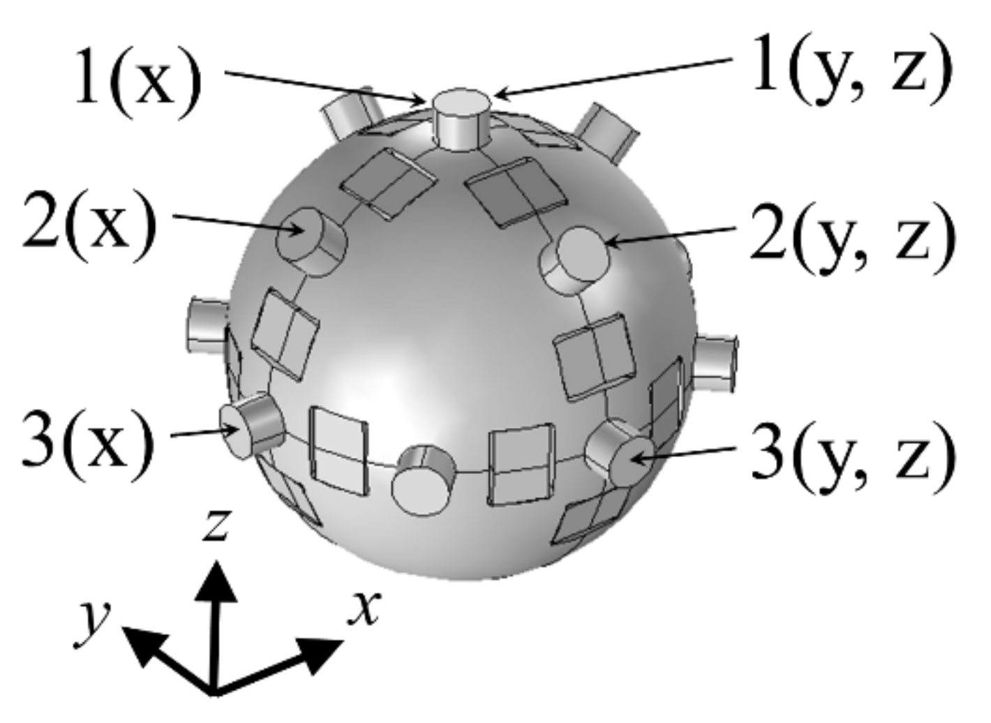
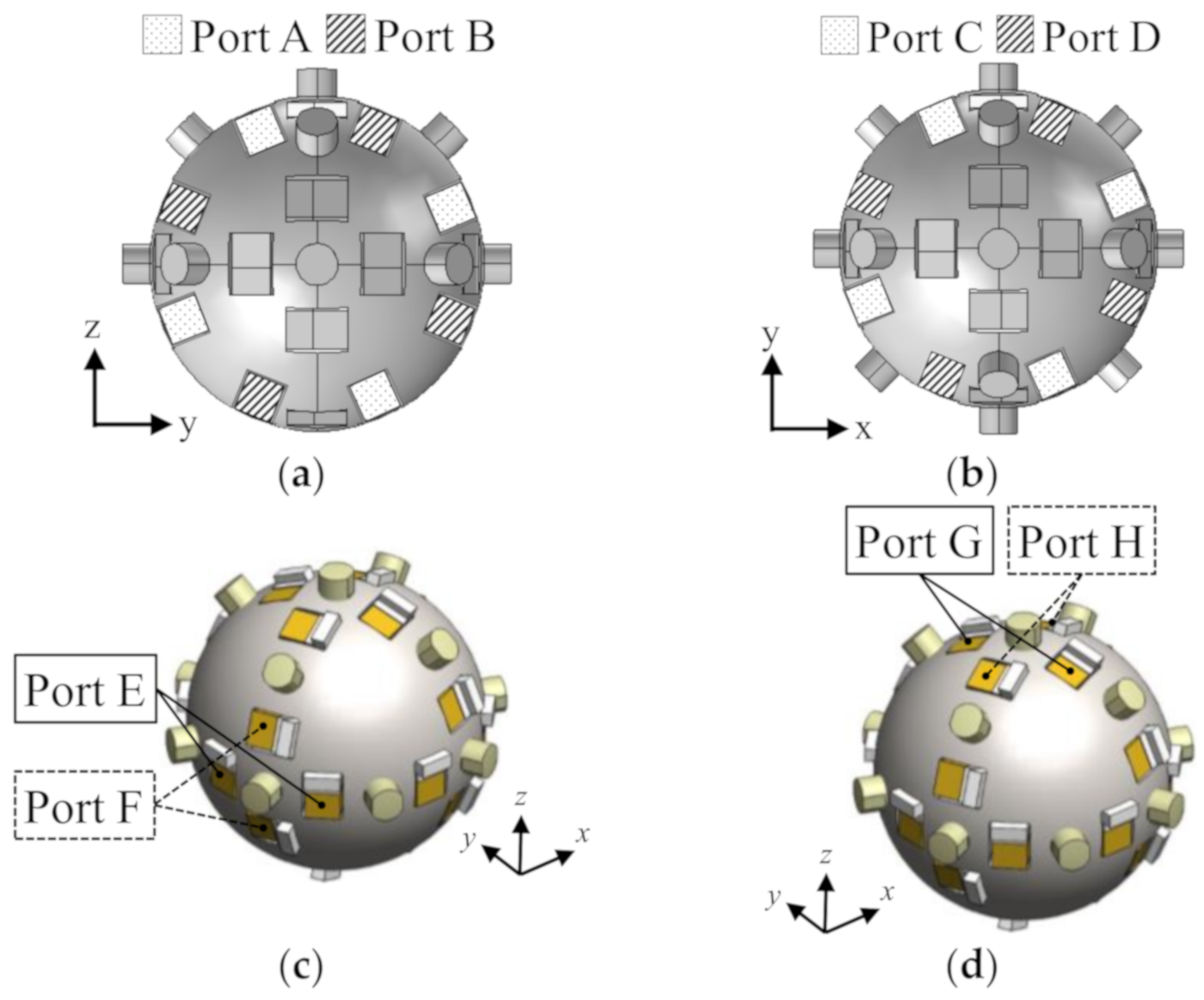
  • By analyzing the electromechanical equivalent circuit of an ultrasonic actuator on ECS, the contribution of each driving projection to each axis rotation was calculated in the case of two types of vibration mode rotation, Type-A and Type-B.
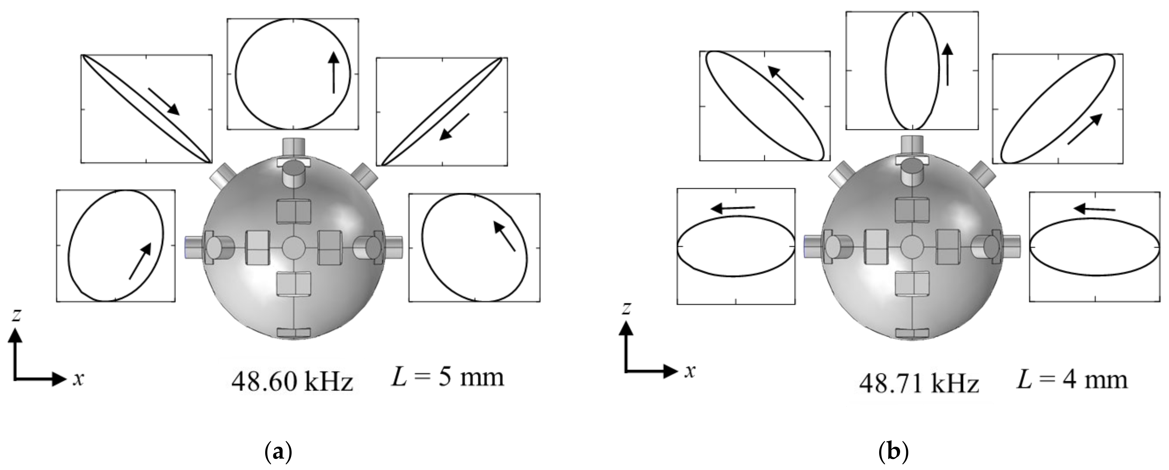
  • The spherical stator was fabricated, and the l2m1-modes and its orthogonal modes excited from each electrical port were confirmed. From the measurement results of the vibration displacement, the vibration mode rotations of Type-A and Type-B were suitable for x(y)-axis rotation and z-axis rotation, respectively.
  • The MDOF-USM using the metal spherical stator was made. The rotor formed from three parts was devised for enfolding the stator and applying a preload from plural directions. The rotations around three axes were confirmed. However, the measured maximum rotation speed was low, and output torque was too small to measure, although input power was too much.
The MDOF-USM using a metal spherical stator was realized. In the future, for further improving the performance, it is necessary to improve methods of excitation and mechanical output through friction and the power factor improvement of the driving circuit. In addition, for weight reduction, a spherical shell stator and a configuration using lightweight elastic materials should be considered. In particular, a strong excitation method for spheres should be studied since there are few reports on this subject.

Supplementary Materials

The following supporting information can be downloaded at: www.mdpi.com/ article/10.3390/act11010027/s1, Figure S1: (a)l2m1-mode; Figure S2: (b)l2m1′-mode; Figure S3:(a)Type-A_mode-rotation; Figure S4: (b)Type-B_mode-rotation.

Author Contributions

Conceptualization, A.M., H.K., H.T. and M.A.; software, A.M. and H.T.; investigation, A.M.; writing—original draft preparation, A.M.; writing—review and editing, M.A.; visualization, A.M.; supervision, M.A.; project administration, M.A. All authors have read and agreed to the published version of the manuscript.

Funding

This research was funded by JSPS KAKENHI, grant number 26289023.

Institutional Review Board Statement

Not applicable.

Informed Consent Statement

Not applicable.

Conflicts of Interest

The authors declare no conflict of interest.

Appendix A

The analysis model shown in Figure 10 can be expressed and analyzed by the electromechanical equivalent circuit [30] shown in Figure A1. The equivalent circuit is drawn using the symbols of electric and electronic circuit elements of the commercial electronic circuit simulator (ECS, Myway Plus PSIM). A mechanical circuit is drawn by electronic and electric elements in this circuit. Therefore, the voltage and electric current correspond to the force and velocity, respectively. Each parameter used in equivalent circuit simulation is shown in Table A1. The details about this equivalent circuit can be found in ref. [29]. The analysis procedure to obtain the maximum trust is described below.
Firstly, the elliptical displacement of the tip of a numbering driving projection generated by each vibration mode rotation was simulated by FEA.
  • Next, the terminals of the normal component and tangential component on the equivalent circuit in Figure A1 were short-circuited to consider only stator without any load.
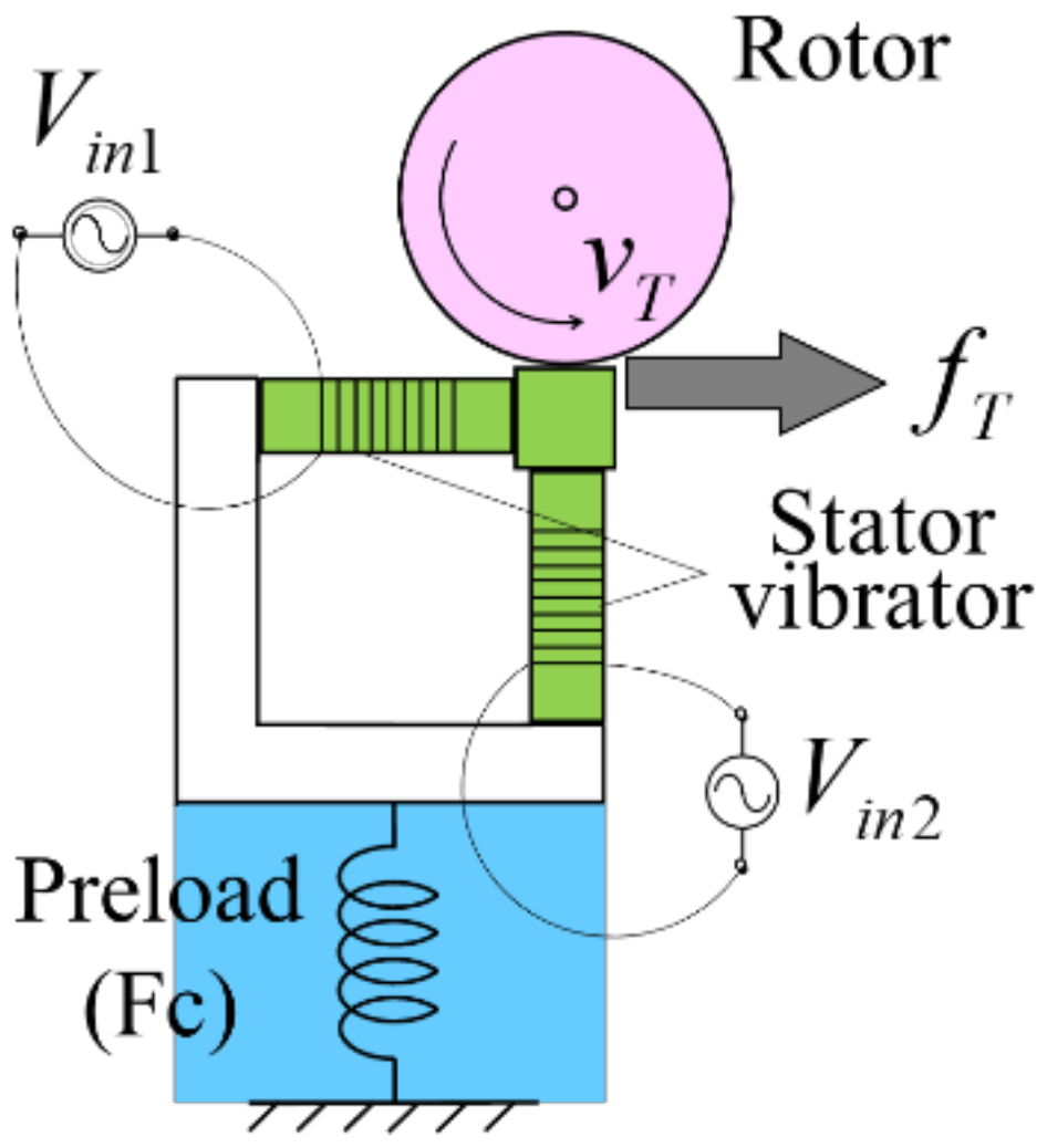
  • The simulated elliptical displacement shown in Figure 8 was reproduced by the instantaneous value of charges at P and Q on the equivalent circuit. Circuit constants and voltage sources were adjusted by trial-and-error until the reproduced displacement was similar to the simulated one. The magnitude and the oblateness of the elliptical displacement were reproduced by the magnitudes of input voltages of Vin1 and Vin2, and the tilt angle of the elliptical displacement was reproduced by the phase difference of both input voltages. In addition, the values of equivalent circuit elements were assumed so that the stator had high output mechanical impedance.
  • The terminal of the tangential component on the circuit was opened for generating the maximum thrust, but the normal component circuit was terminated by serially connected elements DN, 1/KN about the rotor. Because the stator had high output mechanical impedance, the preload FC can be set freely, and the influence on the stator by the preload and the load was supposed to be negligibly small.
  • Finally, the transient analysis of the equivalent circuit was carried out on ECS, and then the mean value of the generated maximum thrust in steady-state (fT) was calculated.
Table A1. Parameters used in the calculation.
SymbolMeanValue
Vin1Applied voltage4~850 VP-P
Vin2Applied voltage3~530 VP-P
thetaPhase between Vin1 and Vin2−90° or 90°
FcPreload30 V
AForce factor5.75 N/V
CdCapacitance of vibrator0.75 μF
DmDamping coefficient of vibrator150 N·s/m
MoMass of vibrator8 × 10−3 kg
KmStiffness of vibrator93 × 106 N/m
DPDamping coefficient of preload element1.0 × 103 N·s/m
MPMass of preload element0.2 kg
KPSpring constant of preload element0.169 N/m
KNNormal spring constant of contact surface1.23 × 109 N/m
DNNormal damping coefficient of contact surface100 N·s/m
MTEquivalent mass of rotor0.49 kg
KTTangential spring constant of contact surface1.23 × 1010 N/m
DlossLoss of rotor
μFrictional coefficient1
fDriving frequency23.5 kHz
Figure A1. An electromechanical equivalent circuit that can be analyzed by an electronic circuit simulator created based on Reference [30].
Actuators 11 00027 g0a1

References

  1. Yano, T.; Kaneko, K. Basic Consideration of Actuators with Multi DOF Having an Identical Center of Rotation. J. Robot. Mechatron. 1995, 7, 458–466. [Google Scholar] [CrossRef]
  2. Wang, J.; Mitchell, K.; Jewell, G.W.; Howe, D. Multi-degree-of-freedom spherical permanent magnet motors. In Proceedings of the IEEE International Conference on Robotics and Automation (ICRA 2001), Seoul, Korea, 21–26 May 2001; pp. 1798–1805. [Google Scholar]
  3. Kaneko, K.; Yamada, I.; Itao, K. A Spherical DC Servo Motor with Three Degree of Freedom. J. Dyn. Syst. Meas. Control 1989, 111, 398–402. [Google Scholar] [CrossRef]
  4. Yano, T. Development of a Synchronous Motor with Three Degrees of Freedom, Theory and Practice of Robots and Manipulators. In Proceedings of the ROMANSY 10: The Tenth CISM-IFToMM Symposium, Gdansk, Poland, 12–15 September 1994. [Google Scholar]
  5. Kumagai, M. Development and control of a three dof spherical induction motor. In Proceedings of the IEEE International Conference on Robotics and Automation (ICRA), Karlsruhe, Germany, 6–10 May 2013. [Google Scholar]
  6. Yano, T. Basic characteristics of a hexahedron-octahedron based spherical stepping motor. In Proceedings of the SPEEDAM 2010, Pisa, Italy, 14–16 June 2010. [Google Scholar]
  7. Li, Z.; Chen, Q.; Guo, P.; Wang, Q. Vibration mode analysis of multi-degree-of-freedom permanent magnet synchronous motor. J. Vibroeng. 2018, 20, 2966–2977. [Google Scholar] [CrossRef]
  8. Maeda, S.; Hirata, K.; Niguchi, N. Characteristics Verification of an Independently Controllable Electromagnetic Spherical Motor. Sensors 2014, 14, 10072–10080. [Google Scholar] [CrossRef] [PubMed] [Green Version]
  9. Nishiura, Y.; Hirata, K.; Sakaidani, Y. 3-DOF Outer Rotor Electromagnetic Spherical Actuator. Int. J. Autom. Technol. 2016, 10, 591–598. [Google Scholar] [CrossRef]
  10. Takemura, K.; Maeno, T. Design and Control of an Ultrasonic Motor Capable of Generating Multi-DOF Motion. IEEE/ASME Trans. Mechatron. 2001, 6, 499–506. [Google Scholar] [CrossRef] [Green Version]
  11. Nishiguchi, S.; Ogawa, K.; Yoshikawa, Y.; Chikaraishi, T.; Hirata, O.; Ishiguro, H. Theatrical approach: Designing human-like behaviour in humanoid robots. Robot. Auton. Syst. 2017, 89, 158–166. [Google Scholar] [CrossRef]
  12. Reingold, E.M. Eye tracking research and technology: Towards objective measurement of data quality. Vis. Cogn. 2014, 22, 635–652. [Google Scholar] [CrossRef]
  13. Oohashi, T.; Toyama, S. Development of spherical ultrasonic motor for space. Appl. Mech. Mater. 2014, 555, 26–31. [Google Scholar] [CrossRef]
  14. Nishizawa, U.; Oohashi, T.; Toyama, S. Evaluation of spherical ultrasonic motor for space in low temperature condition. J. Vibroeng. 2017, 19, 5170–5181. [Google Scholar] [CrossRef]
  15. Abe, T.; Moriya, T.; Irie, T.; Sato, M.; Takeuchi, S. Experimental study of the Π-shaped coiled stator ultrasound motor. Jpn. J. Appl. Phys. 2014, 53, 07KE15. [Google Scholar] [CrossRef]
  16. Toyama, S.; Sugitani, S.; Zhang, G.; Miyatani, Y.; Nakamura, K. Multi Degree of Freedom Spherical Ultrasonic Motor. In Proceedings of the 1995 IEEE International Conference on Robotics and Automation, Nagoya, Japan, 21–27 May 1995. [Google Scholar]
  17. Amano, T.; Ishii, T.; Nakamura, K.; Ueha, S. An ultrasonic actuator with multi-degree of freedom using bending and longitudinal vibrations of a single stator. In Proceedings of the 1998 IEEE Ultrasonics Symp, Sendai, Japan, 5–8 October 1998. [Google Scholar]
  18. Takemura, K.; Kojima, N.; Maeno, T. Development of a Bar-Shaped Ultrasonic Motor for Three-Degrees of Freedom Motion. In Proceedings of the 4th International Conference on Motion and Vibration Control, Zurich, Switzerland, 25–28 August 1998. [Google Scholar]
  19. Yun, C.-H.; Niwano, S.; Friend, J.R.; Nakamura, K.; Ueha, S. Support Mechanism for the Ball Rotor in the Three-Degree-of-Freedom Ultrasonic Motor. Jpn. J. Appl. Phys. 2003, 42, 3000–3001. [Google Scholar] [CrossRef]
  20. Aoyagi, M.; Nakajima, T.; Tomikawa, Y.; Takano, T. Examination of Disk-Type Multidegree-of-Freedom Ultrasonic Motor. Jpn. J. Appl. Phys. 2004, 43, 2884–2890. [Google Scholar] [CrossRef]
  21. Lu, B.; Aoyagi, M.; Takano, T.; Tamura, H. Examination of Sandwich-Type Multidegree-of-Freedom Spherical Ultrasonic Motor. Jpn. J. Appl. Phys. 2010, 49, 07HE24. [Google Scholar] [CrossRef] [Green Version]
  22. Khoo, T.F.; Dang, D.H.; Friend, J.; Oetomo, D.; Yeo, L. Triple Degree-of-Freedom Piezoelectric Ultrasonic Micromotor via Flexural-Axial. IEEE Trans. Ultrason. Ferroelectr. Freq. Control 2009, 56, 1716–1724. [Google Scholar] [CrossRef]
  23. Watson, B.; Friend, J.; Yeo, L. Piezoelectric ultrasonic resonant motor with stator diameter less than 250 μm: The Proteus motor. J. Micromech. Microeng. 2009, 19, 022001. [Google Scholar] [CrossRef]
  24. Aoyagi, M.; Beeby, S.P.; White, N.M. A novel multi-degree-of-freedom thick-film ultrasonic motor. IEEE Trans. Ultrason. Ferroelectr. Freq. Control 2002, 49, 151–158. [Google Scholar] [CrossRef] [Green Version]
  25. Goda, Y.; Koyama, D.; Nakamura, K. Design of Multi-Degree-of-Freedom Ultrasonic Micromotors. Jpn. J. Appl. Phys. 2009, 48, 07GM06. [Google Scholar] [CrossRef]
  26. Lu, B.; Aoyagi, M.; Tamura, H.; Takano, T. Development of a Novel Rotor-Embedded-Type Multidegree-of-Freedom Spherical Ultrasonic Motor. J. Robot. Mechatron. 2012, 24, 876–883. [Google Scholar] [CrossRef]
  27. Mizuno, A.; Oikawa, K.; Aoyagi, M.; Tamura, H.; Takano, T. Examination of High-Torque Sandwich-Type Spherical Ultrasonic Motor Using with High-Power Multimode Annular Vibrating Stator. Actuators 2018, 7, 8. [Google Scholar] [CrossRef] [Green Version]
  28. Nakajima, S.; Kajiwara, H.; Aoyagi, M.; Tamura, H.; Takano, T. Study on spherical stator for multidegree-of-freedom ultrasonic motor. Jpn. J. Appl. Phys. 2016, 55, 07KE18. [Google Scholar] [CrossRef]
  29. Huang, Z.; Shi, S.; Chen, W.; Wang, L.; Wu, L.; Liu, Y. Development of a novel spherical stator multi-DOF ultrasonic motor using in-plane non-axisymmetric mode. Mech. Syst. Signal Process. 2020, 140, 106658. [Google Scholar] [CrossRef]
  30. Sakai, S.; Aoyagi, M. Dynamic characteristic analysis of nonresonance-type ultrasonic actuator using electronic circuit simulator. Jpn. J. Appl. Phys. 2015, 54, 07KE14. [Google Scholar] [CrossRef] [Green Version]
  31. Williams, E.G. Fourier Acoustics: Sound Radiation and Nearfield Acoustical Holography; Academic Press: San Diego, CA, USA, 1999; pp. 183–193. [Google Scholar]
  32. Love, A.E.H. A Treatise on the Mathematical Theory of Elasticity, 2nd ed.; Cambridge University Press: Cambridge, UK, 1944; pp. 236–246. [Google Scholar]
  33. Tomikawa, Y.; Ogasawara, T.; Takano, T. Ultrasonic motors—Constructions/characteristics/applications. Ferroelectrics 1989, 91, 163–178. [Google Scholar] [CrossRef]
Figure 1. Sphere with radius r and definition of spherical coordinates. θ is measured from the polar axis ( 0 θ π ), z. φ is measured in the x, y plane from the x-axis ( 0 φ 2 π ).
Actuators 11 00027 g001
Figure 2. Visualization of spherical harmonics of l = 2 and m = 1. (a) Displacement pattern for spheroidal mode; (b) Deformation in xz-plane; (c) Deformation in plane perpendicular to the z-axis.
Actuators 11 00027 g002
Figure 3. Vibration mode diagrams of the sphere simulated by FEA with l = 2 and m = 1. (a) l2m1-mode; (b) Orthogonal mode, l2m1′-mode. Animation of a simulated vibration mode is available as Supplementary Materials.
Actuators 11 00027 g003
Figure 4. Images of mode-rotation of l2m1-mode. (a) Type-A: Rotation on xz-plane or yz-plane; (b) Type-B: Precession around z-axis. Animations of simulated vibration mode rotations are available as Supplementary Materials.
Actuators 11 00027 g004
Figure 5. Analysis model of displacement form and generate vibration mode rotation. (a) Type-A: Rotation on xz-plane or yz-plane; (b) Type-B: Precession around z-axis.
Actuators 11 00027 g005
Figure 6. Arrangement of 24 MPAs on the surface of the spherical stator.
Actuators 11 00027 g006
Figure 7. Arrangement of driving projections on the spherical stator. (a) Appearance of model; (b) Projection with screw thread.
Actuators 11 00027 g007
Figure 8. Displacement loci at driving projections. (a) Projection length L = 5 mm; (b) L = 4 mm.
Actuators 11 00027 g008
Figure 9. Driving projection number evaluated for each rotation axis.
Actuators 11 00027 g009
Figure 10. Analysis model of USM for equivalent circuit.
Actuators 11 00027 g010
Figure 11. Prototype spherical stator with MPAs and driving projections.
Actuators 11 00027 g011
Figure 12. Definition of Port A to Port H for: (a) x-axis rotation by Type-A; (b) z-axis rotation by Type-A; (c) x-axis rotation by Type-B; (d) z-axis rotation by Type-B.
Actuators 11 00027 g012
Figure 13. Vertical displacement distributions of vibration modes of the stator excited by: (a) Port A and Port B for Type-A; (b) Port C and Port D for Type-A; (c) Port E for Type-B; (d) Port F for Type-B; (e) Port G for Type-B; (f) Port H for Type-B.
Actuators 11 00027 g013aActuators 11 00027 g013b
Figure 14. Prototype MDOF-USM using spherical stator. (a) Rotor parts; (b) Whole view, rotor preload method, and assembly of three rotor parts.
Actuators 11 00027 g014
Figure 15. Rotation characteristics of prototype MDOF-USM using spherical stator. (a) Rotation speed and input power on x(y)-axis rotation; (b) Input current and power factor on x(y)-axis rotation; (c) Rotation speed and input power on z-axis rotation; (d) Input current and power factor on z-axis rotation.
Actuators 11 00027 g015
Table 1. Properties of piezoelectric ceramics used in MPA.
DensityMechanical
Quality Factor
Coupling FactorPiezoelectric Strain ConstantYoung’s ModulusRelative PermittivityDielectric
Dissipation Factor
QmK33d33Y33ε330
kg/m3--10−12 m/V1010 N/m2-%
760020000.693156.514600.4
Table 2. Contribution of each driving projection.
Mode Rotation TypeAxis of RotationContribution of Driving Projection (%)
1(x), 1(y, z)2(x), 2(y, z)3(x), 3(y, z)
Type-Ax, y10098.183.7
z088.6100
Type-Bx, y010068.2
z33.81000
Table 3. Summary of electrical ports, rotation axis, and influence of support rod by mode rotation type.
Mode Rotation TypeRotation Axis Drive PortInfluence of Support Rod
Type-AxA, BLarge, Uneven
zC, DSmall, Even
Type-BxE, FLarge, Uneven
zG, HNot small, Even
Publisher’s Note: MDPI stays neutral with regard to jurisdictional claims in published maps and institutional affiliations.

