Article

A Case Study on the Detection and Prognosis of Internal Leakages in Electro-Hydraulic Flight Control Actuators

Department of Mechanical and Aerospace Engineering, Politecnico di Torino, 10129 Torino, Italy
*
Author to whom correspondence should be addressed.
Actuators 2021, 10(9), 215; https://doi.org/10.3390/act10090215
Submission received: 31 July 2021 / Revised: 27 August 2021 / Accepted: 28 August 2021 / Published: 31 August 2021
(This article belongs to the Special Issue Health Monitoring and Fault Diagnosis on Actuation Systems)

Abstract

:
Electro-hydraulic servo-actuators (EHSAs) are currently considered the state-of-the art solution for the control of the primary flight control systems of civil and military aircraft. Combining the expected service life of a commercial aircraft with the fact that electro-hydraulic technology is employed in the vast majority of currently in-service aircraft and is planned to be used on future platforms as well, the development of an effective Prognostic and Health Management (PHM) system could provide significant advantages to fleet operators and aircraft maintenance, such as the reduction of unplanned flight disruptions and increased availability of the aircraft. The occurrence of excessive internal leakage within the EHSAs is one of the most common causes of return from the field of flight control actuators, making this failure mode a priority in the definition of any dedicated PHM routine. This paper presents a case study on the design of a prognostic system for this degradation mode, in the context of a wider effort toward the definition of a prognostic framework suitable to work on in-flight data. The study is performed by means of a high-fidelity simulation model supported by experimental activities. Results of both the simulation and the experimental work are used to select a suitable feature, then implemented within the prognostic framework based on particle filtering. The algorithm is at first theoretically discussed, and then tested against several degradation patterns. Performances are evaluated through state-of-the-art metrics, showing promising results and providing the basis towards future applications on real in-flight data.

Graphical Abstract

1. Introduction

Primary flight control systems and the servo-actuators used to control them are regarded as safety critical and represent one of the most significant causes of operation disruption in both civil and military aviation. The development of an effective prognostics and health management (PHM, refer to Table A1 for acronyms.) framework for such systems, could lead to a significant technological advancement providing several benefits both at the aircraft and at the fleet level, positively impacting the vehicle reliability and dispatchability by avoiding un-predicted aircraft-on-ground situations, and significantly reducing the additional costs associated with takeoff delays or cancellations, re-routing, or in-flight turn back. As a further effect, an effective PHM system would allow to streamline the logistics of the spare parts and of the maintenance operators, thus reducing maintenance time and cost, and simplifying the troubleshooting process. The impact of the costs associated with unnecessary or unpredicted maintenance and with the effects of flight disruption is difficult to precisely evaluate as it is dependent on the aircraft type, its usage, the maintenance policies of the airliner and the contingent situation related with the failure occurrence. To provide a rough estimate, IATA projections evaluated in US$ 65 billion [1] the expected global spending for 2020, while another publication on integrated disruption management and flight planning demonstrated that just-in-time maintenance can help to reduce the downsides of flight disruptions, generating an estimated 6% cost reduction for the airline [2]. Although the spending for flight control actuators is expected to be just a fraction of the total, the contribution gained from the introduction of an effective health monitoring system for aircraft flight control actuators will still provide significant cost savings. In other sectors, such as the military aviation, PHM would also provide additional strategical information, that could be potentially employed to improve the aircraft survivability and maximize its availability. A real-time, on-board PHM system could be in principle able to inform whether an aircraft can continue the mission or must return to base, and eventually reconfigure the system to mitigate the fault-to-failure progression or reduce the effects of the degradation on the system performances [3]. The development of PHM frameworks for primary flight control systems is still a rather unexplored subject, despite representing one of the safety-critical aircraft systems. This can be mainly attributed to low availability of relevant data, major difficulties in modeling and testing and generally a lack of sound understanding of the failure mechanisms affecting the most common architectures employing electro-hydraulic servo actuators (EHSAs). Most of the available literature is focused on electro-mechanical actuators, which application to primary flight controls is however limited to UAVs and experimental aircraft due to a few unresolved technological barriers, the most important being the sensitivity to certain single point of failures that can lead to mechanical jams [4]. For these reasons, electro-hydraulic servo actuators are still the most used solution for the primary flight control systems of new commercial aircraft and represent the vast majority of the actuation systems, both of the aircrafts already in service and of those expected to keep operating in the upcoming years. As such, the definition of an effective prognostics and health management system for EHSAs would be an attractive goal to improve fleet management for both new and legacy aircrafts. Literature on prognostics for EHSAs is currently rather scarce, and mostly focused on a few single faults scenarios; in [5], the authors presented one of the few research papers focused on the use of hydraulic actuators for aviation. In it, the authors propose to develop a prognostic system for the F/A-18 stabilizer electro-hydraulic servo-valves through a combination of neural network error-tracking techniques, fuzzy logic classifiers, Kalman filter state predictors, and feature fusion strategies. In [6] the authors proposed a new resampling scheme based on Hellinger’s distance and verified their results on accelerated fatigue tests on a few structural components of the actuator, while a fault diagnosis scheme for electro-hydrostatic actuation system is briefly described in [7]. Leakage detection was also the focus of the works presented in [8], where the issue was studied from the perspective of an industrial actuator, proposing a fault detection scheme based upon Adaboost-BP neural network, which proved to be more effective than methodologies base upon random-forest algorithms. Although extremely promising, this methodology was not tested against data sets representative of the operating conditions typically encountered by real flight-control actuators (wide temperature variance, unpredictable external loads, significant variations of the inlet and return channel pressures). Recently, the authors of this paper have investigated the effects of several faults mode on electro-hydraulic servo actuators (EHSA) through theoretical [9] and experimental [10] activities, addressing the feasibility of the development of a dedicated PHM system for a fixed-wing aircraft without resorting to additional sensors, thus using only the signals already available on-board. The investigated fault modes included degradations affecting both the servo-valve (backlash and crack progression within the feedback spring, degradation of the torque motor magnets, mechanical strain of the jet pipe) and the actuator (occlusion of the by-pass channel, wear of the sealing elements, backlash in the rod-end). Similarly, an early evaluation of the effects of a few significant degradations for electro-hydraulic servo actuators employed in the stability control augmentation system of an in service helicopter is provided in [11,12]. These early studies concurred on the feasibility of a PHM system for EHSAs and addressed the possibility to successfully monitor and identify a few selected failure modes through a purely data-driven approach, while providing early indication on the possibility to prognose such degradations through a particle-filtering framework, but currently lack of experimental confirmation. According to the failure mode effect and criticality analysis (FMECA) analysis provided in these works, the most frequent cause of return from the field for EHSAs are the occurrence of an excessive null-bias within the servo-valve and excessive leakages. This paper provides the results of an advancement towards the definition of an operative prognostic tool focused on the detection, identification, and prognosis of the internal leakage of an EHSA employed as a primary flight control actuator in a wide-body aircraft currently in service. The paper is an autonomous continuation of the work presented in [9,10] and is organized as follows; at first, the case study under analysis is presented, highlighting its peculiarities and operational modes. The adopted approach is then presented, and both the simulation model and the experimental set-up introduced. The PHM framework is then described in detail, finally leading to a discussion on its performances, computational requirements, and applicability constraints.

2. Case Study

The case study considered for this paper is the actuation system of a primary flight-control surface of a wide-body commercial aircraft which is currently in-service, and was the object of the feasibility study reported in [7]. The system, depicted in Figure 1, controls the aerodynamic surface through an active-stand-by strategy. In this configuration, the flight control computers actively provide the position command to only one of the two actuators, while the second is kept in by-pass mode through the activation of a dedicated mode valve, providing a desired damping effect on the tab dynamics and acting as a back-up in case a failure is detected in the active EHSA. Unless an emergency condition occurs, the roles of the two EHSAs are periodically exchanged. Each EHSA is controlled through a two-stages electro-hydraulic servo-valve, while a two-position, normally closed valve acts as the mode-switching element. An accumulator ensures that the pressure on the supply line does not drop below a minimum threshold and is necessary due to the length of the piping connecting the flight control actuators with the central hydraulic power generation units. The servo-valve features a jet-pipe interface between its two stages, translating the current signal supplied by the EHSA controller into the displacement of its spool, thus determining the flowrate exchanged between the hydraulic system and the actuator.
The actuator presents two asymmetrical chambers, with the highest acting area corresponding to the extraction movement; two spherical joints connect each end of the EHSA with the airframe structure on one side and the aerodynamic surface on the other. A linear variable differential transducer (LVDT) measures the position of the actuator rod relatively to the rod-end at the airframe side; this signal is then used to close the feedback loop towards the controller, which makes use of a proportional-integrative regulation law with dead-band and anti-wind-up logics. The EHSA is supplied and controlled through a dual electrical interface with two independent electrical lanes. Whenever the actuator is in “active” state, the solenoid valve is supplied, imposing a movement of the mode valve spool to connect the actuator ports with the servo-valve. To achieve the stand-by conditions, the solenoid valve is instead de-energized. The hydraulic lines connected to the servo-valve control ports are hence blocked and the hydraulic fluid passing from one chamber to the other is forced through a damping orifice, providing a resistant force on the actuation system proportional to the actuator velocity. This function is required to avoid the possible insurgence of flutter, or aero elastic instability, in case of failure of both EHSAs, a catastrophic event which can easily cause the loss of the aircraft. Other than the LVDT, each EHSA is also equipped with a sensor suit used to perform the continuous built-in-tests (C-BIT) monitoring of potentially critical failures occurrence (C-BIT) as well as some dedicated pre-flight built-in-tests (P-BIT), designed to ensure that no dormant failures exist before take-off. For the selected case study, the sensor suit includes a dedicated LVDT measuring the linear position of the servo-valve spool, a differential pressure sensor mounted across the actuators’ chambers and another LVDT measuring the position of the mode valve spool.
Together with the command signals, these measures allow to successfully detect the occurrence of critical failures to the most significant components of the EHSA. Previous studies also provided the preliminary confirmation that the same signals can be used to perform PHM activity [10].

3. Materials and Methods

The approach followed in this paper follows the template for preliminary PHM studies provided in [9] and is a direct follow-up of the feasibility analysis described in [10]. To better introduce the work presented in this paper, the main conclusions of the feasibility analysis are hereby reported. According to [13], the definition of a PHM system for a given use-case must always start from a dedicated failure mode effect and criticality analysis (FMECA), which main purpose is to evaluate which failure modes are expected to be most frequent and critical, and at the same time to provide an early estimate on their observability. According to early investigations, the occurrence of excessive leakage within the actuator is between the most common cause of return from the field for EHSAs currently employed in primary flight control systems [9]. Extensive simulation activities, supported by experimental tests allowed to establish the feasibility of a PHM system for EHSAs through a combination of in-flight and pre-flight analysis, providing some preliminary conclusion on the feature selection process. The prognostic routines were however defined within the perimeter of a feasibility study and tested against a single case-study configuration. Aim of this work is to further push towards the definition of an operating PHM system for EHSAs by refining the prognostic algorithm and checking its performances through extensive simulation campaigns against different case-study configurations.

3.1. Simulation Model

To generate data-sets representative of both nominal and faulty conditions we adopted the dynamic model detailed in [14] and experimentally verified for nominal health conditions. Each component is described through physics-based equations without resorting to black-box or grey-box approximations. The servo-valve model is derived from the seminal work of Urata [15,16,17], who first provided a complete physics-based formulation of this class of components.
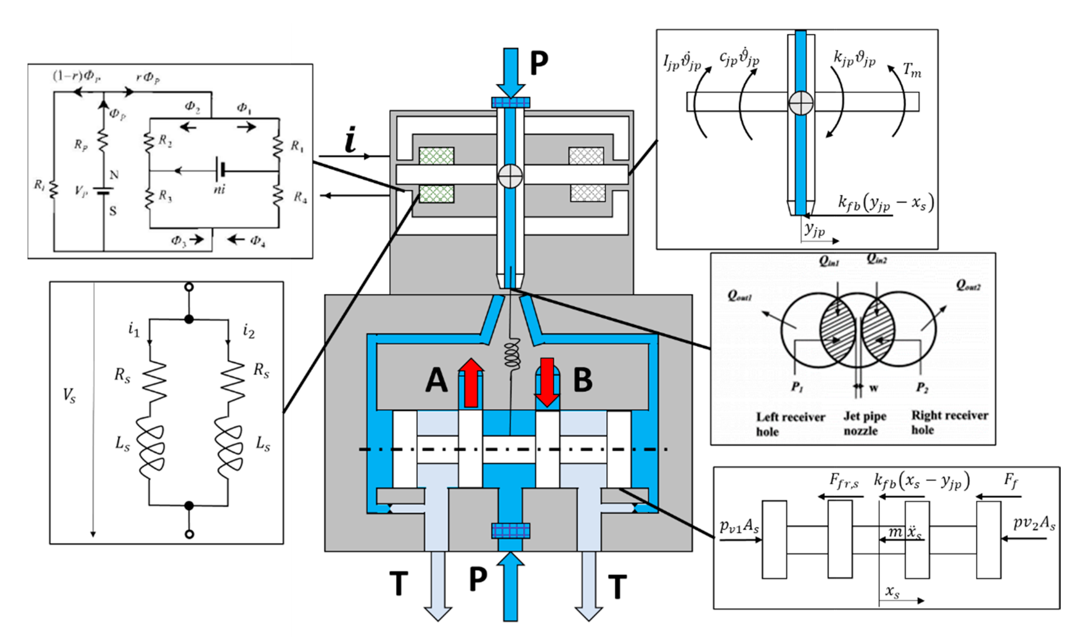
This description does not rely on linearized gains, requiring instead the accurate estimate of the device geometry and of the characteristics of its components. Although more complex, this approach allows to introduce physics-based representation of several fault modes, hence allowing to generate more realistic results. As shown in Figure 2, the servo-valve model can be at first divided into a few subsystems, each representative of a particular component. The electrical dynamics of the first stage windings can be modeled as a simple two-coils parallel circuit supplied at a voltage V S and featuring equal resistances R s and inductances L s :
{ V S = [ R s ( 1 W s ) ] i 1 + L s d i 1 d t V s = R s i 2 + L s d i 2 d t
The parameter W s ranges between zero and one and can be used to simulate the presence of a short in the first winding. The torque T m exerted by the torque motor can be described as a function of the magnetic flux generated by the permanent magnets ϕ P , the servovalve currents i 1 and i 2 and the size of four gaps within the magnetic circuit. Under this representation, the degradation of the permanent magnets can be represented through the reduction of the magnetic flux ϕ P . The torque provided then becomes the input signal for the dynamic equilibrium of the jet-pipe, which rotation ϑ j p is determined by the combined effect of the anchor stiffness k j p , its damping coefficient c j p and its moment of inertia I j p . The feedback spring acts on the equilibrium through its stiffness k f b . The eventual strain of the anchor structure can be modelled as an offset y d i s t affecting the position of the discharge orifice y j p :
{ T m = T m ( i 1 , i 2 , Φ P ) T m k j p ϑ j p k f b [ x s ( y j p + y d i s t ) ] c   ϑ ˙ j p = I j p ϑ ¨ j p
The anchor oscillation imposes a pressure differential at the opposite sides of the servo-valve spool by distributing the flow passing through the jet-pipe to the two receiving ports of the hydraulic amplifier, which depends on the geometry of the receiving ports and on the supply pressure p s . The behavior of the spool displacement x s can then be represented considering the equilibrium dynamics provided by the pressure drop across the control chambers ( p v 1 p v 2 ) , the friction force F f r , s and the steady-state flow force resultant F f = i ρ Q i v i cos ( ϑ i ) , itself dependent on the flowrates Q 1 and Q 2 exchanged with the actuator, the local speed of the fluid v i and the expected flow deflection angle ϑ i . The value of the flowrates Q 1 and Q 2 are computed according to the variable hydraulic resistances representing the metering section and the leakage path across the main stage of the servo-valve, and depends on the local Reynold’s number and the ports geometry [14]:
( p v 1 p v 2 ) A s k f b ( x s y j p ) c x ˙ s F f F f r , s = m s x ¨ s
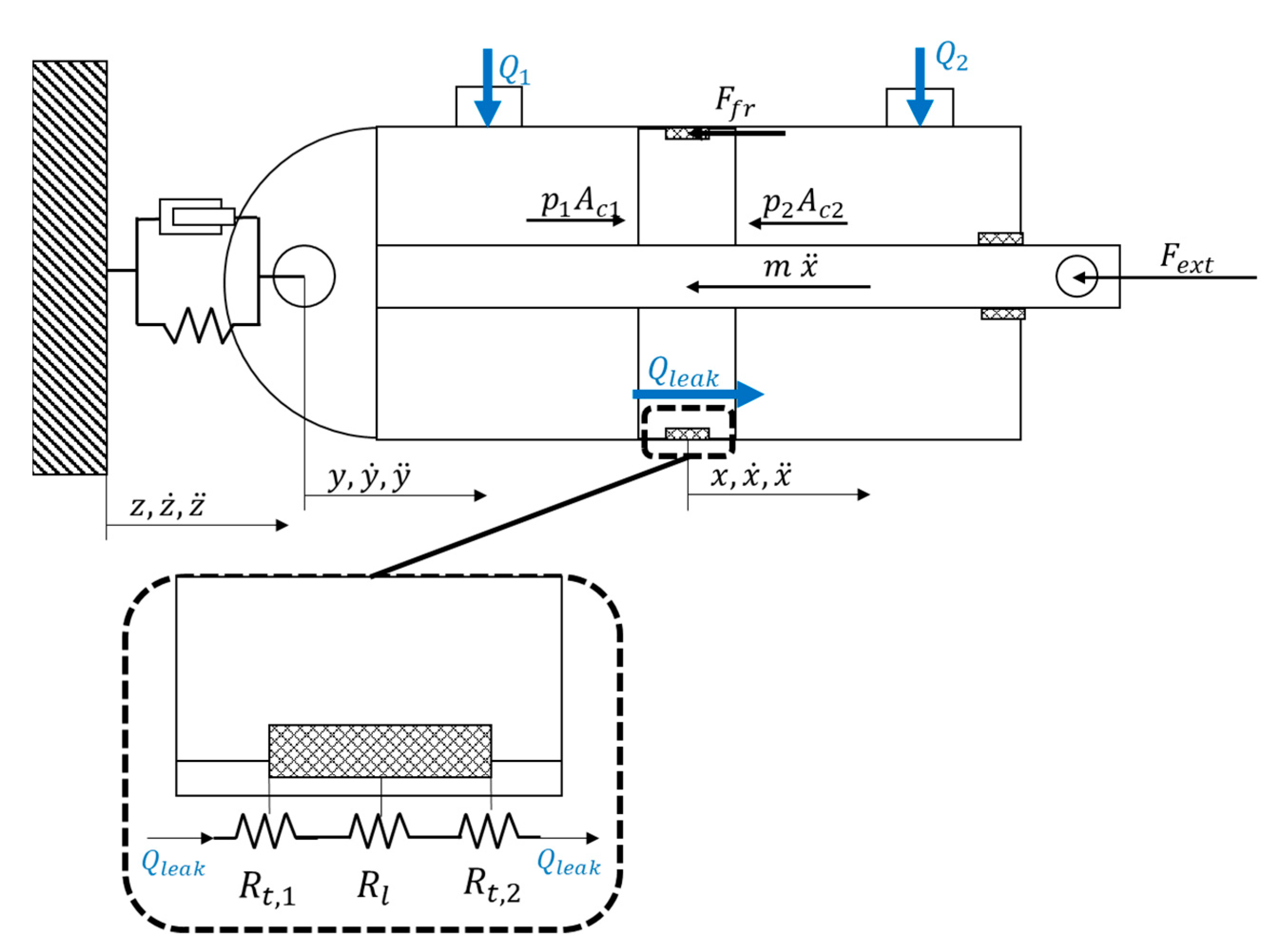
An overview of the actuator dynamics is depicted in Figure 3. The rod displacement x can be obtained through the expressions of Equation (4) where the trust areas of the two chambers are assumed equal to A c , 1 and A c , 2 , while the Bulk modulus and the chambers volume at mid stroke are addressed with β and V 0 , 1 ,   V 0 , 2 :
{ Q 1 A c , 1 ( x ˙ y ˙ ) Q l e a k = V 0 , 1 + A c , 1 ( x y ) β d p 1 d t Q 2 + A c , 2 ( x ˙ y ˙ ) + Q l e a k = V 0 , 2 A c , 2 ( x y ) β d p 2 d t p 1 A c , 1 p 2 A c , 2 F f r γ x ˙ = m x ¨ p 2 A c , 2 p 1 A c , 1 F f r γ y ˙ + k s ( z y ) + c s ( z ˙ y ˙ ) = m c y ¨
The friction forces due to the contact between the sealing elements and the components in relative motion are addressed with F f r and computed according to [18], while γ and m are respectively a viscous friction coefficient and the equivalent mass representative of the combined inertia of the rod and of the linkage. The cylinder dynamics is also represented as a function of its mass m c ; to also model the effects of the vibrations induced on the actuator by the airframe, the attachment on that side of system is modelled as a spring-damper system of stiffness k s . The flowrate lost due to internal leakage Q l e a k is modelled according to a series of laminar and turbulent resistances, where each element is function of the system geometry.
The leakage path is then modelled as in Equation (5):
{ ( p 1 p 2 ) = R l Q l e a k + R t 1 Q l e a k 2 + R t 2 Q l e a k 2 R l = 12 µ L l e a k k c w l e a k h l e a k 3 + R p R t 1 = ρ 2 [ c d 1 ( R e ) ( w l e a k h l e a k ) ] 2 R t 2 = ρ 2 [ c d 2 ( R e ) ( w l e a k h l e a k ) ] 2
The term R l represent the sum of the hydraulic resistances modeling the laminar flow within the small gap of heigh h l e a k between the sealing element and the cylinder as well as the permeability of the seal R p . L l e a k is the length of the leaking path, while w l e a k is its width. The conformity coefficient k c considers the irregularity of the contact between the percolation channels and the seal seat. R t 1 and R t 2 represent the occurrence of turbulent flow at the inlet and at the outlet of the path, where the coefficients C d 1 and C d 2 are represented as a function of the local Reynold’s number according to the expression reported in Equation (6), which can be used for small calibrated orifices for Reynold’s numbers lower than 5000. It is coherent with results provided by [19] and has been employed to model leakage flows for other applications by authors in [20]:
C d = 0.22 ln ( 1 + R e )
When the piston slides inside the cylinder there is an additional flow, known as Couette flow, determined by the entrainment of hydraulic fluid by the moving piston Q C , equal to:
Q C = k c 2 L l e a k h l e a k x ˙
The total flow through the leakage path can then be computed as the sum of Q l e a k and Q c . The occurrence of wear may cause in time the occurrence of cuts, tears or extrusions of the sealing elements hence leading to increasing leakage. Wear of the sealing elements is a complex subject and can origin from a wide variety of events (abrasion, adhesion, cutting) [21]. To simulate a representative number of fault-to-failure process within a feasible timeframe and avoid the use of time-consuming co-simulations between different environments, a few simplifying hypotheses have been defined. As such, it is assumed that the only wear mechanism in play is the abrasive one, and that the process occurs uniformly across the whole seal section. Under these assumptions, wear can be modelled according to the Archard’s model [22], which hence lead to a progressive, uniform increase of the leaking path height h l e a k . The model of the by-pass actuator is derived from that described in Equation (4), and the by-pass flowrate is determined applying a turbulent efflux law to the calibrated orifice. The aerodynamic surface is also modelled considering its structural stiffness and damping, and the aerodynamic force acting on it is evaluated considering the lift and drag coefficient of the considered wing, the attach angle, and the eventual occurrence of gusts through the Dryden’s formulation.

3.2. Experimental Set-Up and Design of Experiment

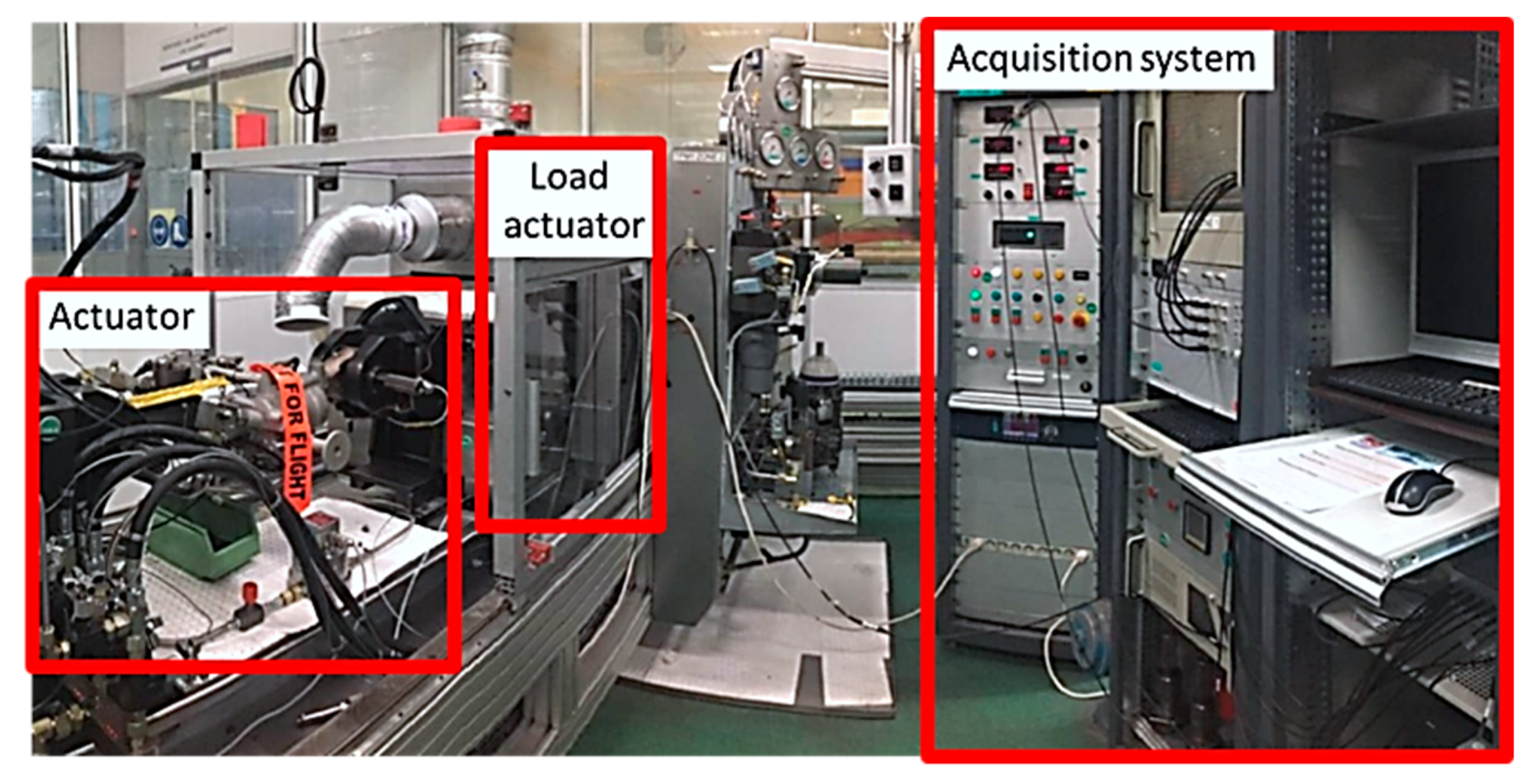
The experimental activities meant to support the simulation campaigns have been performed on the modified production test-bench depicted in Figure 4 and already adopted for the feasibility study described in [10] to support the definition of a preliminary health monitoring scheme for a wide array of faults affecting either the servo-valve or the actuator. The actuator under analysis is controlled in position while acting over an equivalent translating mass, simulating the inertia of the aerodynamic surface, while a second hydraulic actuator controlled in force can be used to impose a resistant or a driving action over the tested device. The acquisition and control module is instead used to define the position command, to process the signals provided by the test bench sensors and store these data in an external memory drive, ready to be further analyzed. The signals available within the test-bench are used for both monitoring the experimental campaign and extract data to support the results of the simulation effort. These signals can be roughly divided into three major categories. To the first category belong all those signals normally present within the electronic control unit of the electro-hydraulic servo actuator under analysis. Part of this category are the signals provided by the LVDT integral with the actuator rod, used to measure its position and infer its speed, by the pressure sensors, present in both actuator’s chambers, and by a second LVDT used to monitor the position of the servo-valve spool. A few signals generated by the test bench itself are also available, such as the control signals (set, feedback and error), as well as the intensity of the currents injected in the first stage of the servo-valve. Signals present on the test-bench and possibly available in the real application within other aircraft systems belong to the second category; here we find the measures of the supply and return channels’ pressures, the temperature of the oil and of the test environment. The third and final category addresses the additional “monitoring” sensors, employed during the tests for degraded conditions to monitor the size of the injected defect. The test bench is covered by a safety glass during the tests, while cold air pumped by the conditioning system of the test facility can be used to avoid overheating due to prolonged usage.
The set-up also allows to impose variations over the supply pressure sent to the actuator by manually acting on the pressure reducer valve interposed between the test bed and the remote hydraulic power generator. The system was at first tested with no additional modifications with an array of sinusoidal, step and ramp commands mimicking the on-ground dedicated sequence defined in [9], while the load actuator was kept at tank pressure.
Tests were repeated under different supply pressure setting while monitoring the oil temperature. The most rigorous approach to validate the model under degraded conditions is to physically inject degradations of known severity or to introduce modifications to the test bench able to reproduce the effects of the presence of one or more faults. To limit the tests cost and avoid damage to an otherwise operating actuator, it was instead decided to modify the test bench to replicate the effect of an increasing internal leakage short-circuiting the two actuator chambers by means of a manually operated variable restrictor. A digital flowmeter was employed to measure the flowrate passing through this additional by-pass path. Tests were then performed through two sequential steps. At first, the EHSA was slowly pressurized while a slow position ramp was commanded to the actuator. This operation was needed to extrapolate a steady-state estimate of the leakage passing through the dedicated by-pass valve while measuring the pressure drop across the chambers, hence allowing to regulate consistently the manually operated restrictor. This operation is necessary since the dynamics of the digital flowmeters typically available on production sites is much slower than the typical dynamics of EHSAs for primary flight controls. Once that the desired value of leakage was obtained, the actuator was brought back to its mechanical zero and commanded with a repeating sequence of stimuli designed to stress the actuator according to a variety of types of command signal. Tests were then repeated varying the supply pressure between the 85% and the 100% of its nominal value to better characterize the uncertainty associated with the feature extraction process on a hypothetical application to in-flight actuators. Oil temperature was moreover monitored throughout the tests, but it was not possible to actively control it due to the layout of the hydraulic plant of the test facility.

4. Feature Selection and Preliminary Results

Feature selection is the process through which a signal or combination of signals representative of a certain degradation status is obtained. According to [13], a feature suitable for prognostics must carry high value information, hence a high signal-to-noise ratio, must be representative of the selected fault growth, thus be highly correlated with the fault severity, and possibly independent from the occurrence of other degradation modes. This preliminary, but paramount, stage of the development of a novel PHM framework comes with a few challenges, the most important of which are the representation of the uncertainty that can affect the feature extraction in a real operational scenario and the study of the effects that other degradations might have on the selected feature. The first issue would require studying the system behavior when exposed to the whole array of operational conditions and external disturbances, each repeated according to the expected frequency of occurrence during service. The second issue instead requires studying the system behavior in response to the occurrence of the most probable faults, even if only one failure mode is being investigated for prognostics, avoiding the definition of non-robust features which may trigger false alarms or cause incorrect classifications of the on-going degradations. In principle both activities should be pursued through simulation and experimental campaigns; the cost of the experimental campaign can however raise to non-sustainable levels if destructive tests are involved. To limit the cost concerns while still providing reasonably robust results, a different approach was pursued. At first, the simulation model is verified against the experimental dataset obtained for a healthy actuator, and then used to simulate its behavior over a range of realistic operational scenarios representative of more than 100 flight hours. The models of nine other actuators are then obtained modifying the geometrical and physical properties of the EHSA tuned on the experimental data applying modifiers selected from normal random distributions representative of the expected production tolerances. Simulations are then performed on these EHSAs as well. Flight simulations are composed of combinations of position commands and aerodynamic forces dependent on the considered flight segment (take-off, cruise, descent, landing). Temperatures at ground level are randomized, while air temperatures during flights are dependent on the expected aircraft altitude as described in [23]. This first database is built to be representative of the actuator behavior when healthy. Faults of known, increasing severity are then inserted within these models. Experimental activities are then focused on the EHSA’s internal leakage issues and used to verify the simulation findings and strengthen the feature selection process.

4.1. Results of the Simulation Campaigns

The simulation activity performed for this paper directly stems from the one presented in [9,10], where fewer flight hours were considered. Despite the wider scope of this new investigation, results largely overlap and are then only briefly presented for ease of reading. Results of these early simulation campaigns are reported in Table 1 and Figure 5, providing some early indication on the features that can be in first approximation adopted to build a PHM system for the considered EHSAs configuration. Focusing on the internal leakage issues object of this paper, results depicted in Figure 5 show that it can be reliably detected monitoring the moving average of the reciprocal of the pressure gain of the servosystem, estimated as the ratio between the RMS of the spool displacement and of the pressure drop, each computed on moving windows of 1 s. During operations, the occurrence of internal leakage causes a reduction of the pressure drop across the actuator’s chambers. The effect of such pressure drop reduction affects the positioning of the actuator, especially in presence of external load and null, or extremely low, speed, leading the control system to react. The servo valve is then supplied with currents of higher intensity, thus increasing its spool displacement, finally causing a reduction of the pressure gain. Simulations showed that the leakage was more evident with a combination of an external load and low speed of the actuator. As such, the feature is computed only when the actuator speed x ˙ falls below a threshold x ˙ t h r .

4.2. Experimental Activities

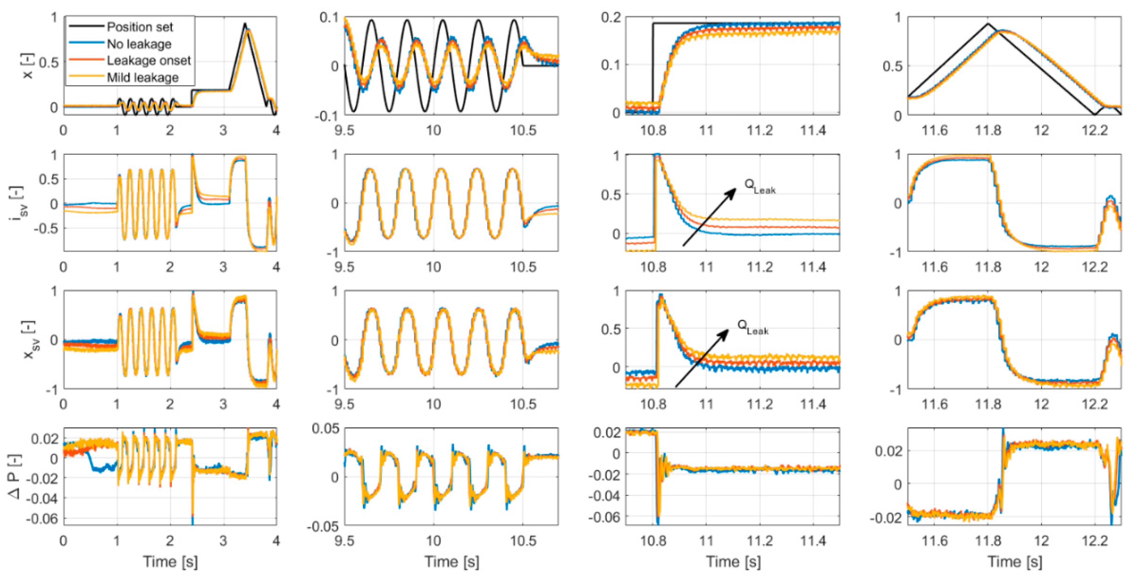
Experimental activities were performed on two EHSAs of the same class, the first was in nominal health conditions, while the second was an actuator returned from service and exhibited significant internal leakage during troubleshooting. Both actuators were subjected to the same test procedure described in Section 3, under three different load levels (no load, 30% 60% of the stall load). The feature f H A L e a k was computed for each test. Results of a few runs are provided in Figure 6, where the effect of the leakage occurrence mirrors the results of the simulation campaign. The results presented in this figure were obtained in presence of an external load equal to the 30% of the actuator stall load. Please notice that results are provided as non-dimensional to avoid the disclosure of proprietary data. Results of the experimental activities were coherent with the simulation campaign and confirmed the effectiveness of focusing the feature extraction process on correspondence of low-speed conditions.
The behavior of the feature f H A L e a k computed on the experimental data set is instead depicted in Figure 7, where it is compared with the simulation results showing a good correspondence. Even more importantly, the feature exhibits a linear correlation with the fault growth, which is the optimal condition for prognostic purposes.

5. The PHM Algorithm

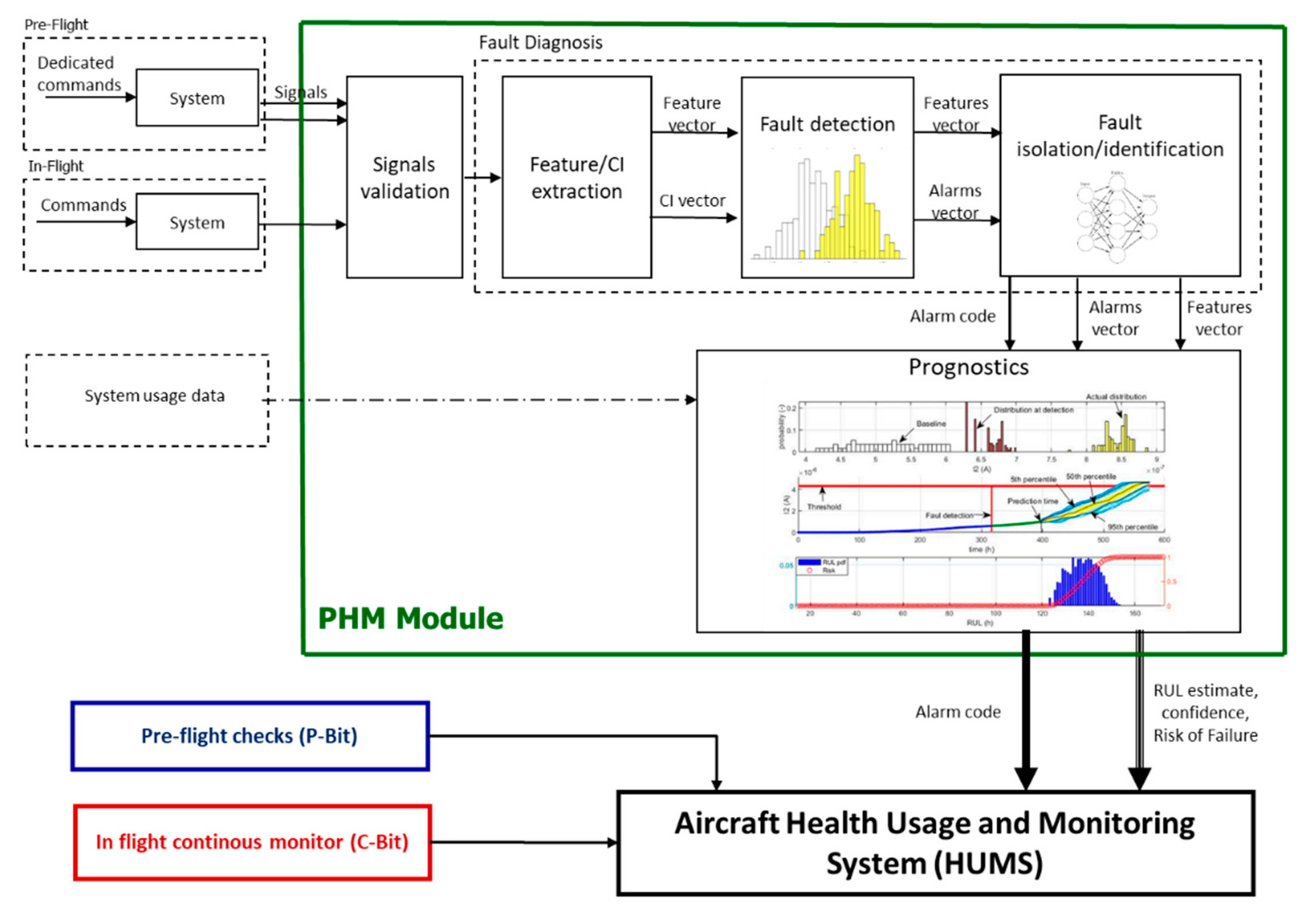
The architecture of the PHM system firstly proposed in [9] is depicted in Figure 8, where the three functional step of feature extraction, fault diagnosis and failure prognosis are highlighted. The extracted features are at first routed to the fault diagnosis module, which collects data and performs the anomaly detection and fault classification. The prognostic routine hence makes use of the features and of the classifier output to provide an estimate of the remaining useful life (RUL) of the system, along with the evaluation of the risk of failure.
It is important to underline that the PHM framework hereby presented is meant to be exclusively dedicated to maintenance and strategic purposes, as the feasibility analysis provided in [10] observed that the technology is not mature enough to deal with safety issues. As such, the PHM system must work in tandem with the monitoring procedures currently employed on servo-actuators, designed to observe the occurrence of critical failures within the EHSA. These procedures provide three different functions, “C-BIT”, “P-BIT” and “I-BIT”. “C-BIT” routines are continuously performed during flight to detect the occurrence of failures which have the potential to be safety critical for the entire aircraft. “P-BIT” are specific checks performed during the pre-flight operations to detect dormant failures which might affect the components used to put in safe mode the actuator whether a failure occurs. Finally, the “I-BIT” are used to check the conditions of a few selected components. This section presents the PHM framework in detail and provide a first evaluation of its performance when applied to the detection and prognosis of excessive leakages within the EHSA. At first each PHM function is described, while highlighting their peculiarities. Hence the algorithm is run over several simulated degradation patterns and its behavior evaluated according to the most common metrics.

5.1. Fault Diagnosis

The fault diagnosis process is based on two subroutines, the first dedicated to the fault detection and the second performing the classification of any observed anomaly. The fault detection routine compares the running distribution of each feature against a baseline obtained for healthy conditions. In this work, the baselines were derived from the synthetic data obtained during the simulation campaign described in Section 4, partially confirmed by the experimental results presented in the same paragraph. In practice, such baseline distribution can be obtained monitoring the behavior of the EHSA during its first flight-hours. A threshold, variable for each fault mode, is defined for each fault declaration. For the case-study under analysis, the internal leakage, the fault declaration is provided whenever the 95% of the running distribution overcomes the 95th percentile of the baseline distribution. Although more complex methodologies are available, this simple, data-driven technique widely is often reported in literature due to its low computational requirements and its capability to easily adapt to the peculiarities of each actuator [13,24].
At each time stamp t the fault detection algorithm also estimates the confidence c i , t associated with the i-th fault mode as the probability that the associated feature y i , t is higher than its threshold y t h :
c i , t = p ( y i , t > y t h )
The outputs of the fault detection algorithm are the feature vector and an alarm vector, that is an array of Boolean elements which assumes value 1 when the associated fault is detected and 0 if no anomaly is observed.
The fault classification is based on a linear support vector machine, which was trained and tested on two different subsets of the synthetic database obtained during the first simulation campaign. In [10], authors observed that although the optimal solution for the fault classification problem would be to monitor the EHSA behavior both in flight and during dedicated pre-flight check. Early results however suggested that the successful classification rate for the EHSA internal leakage fault was high even considering only the fata collected during the simulated flight (88% success at the degradation onset, 99.8% success rate for mild degradation). As such, the classifier used in this paper only analyzes in-flight data. To improve the separation between the regions of the features space associated with the occurrence of different faults, we provide as input to the classifier the element-by-element product of the features vector with the alarm vector.

5.2. Failure Prognosis

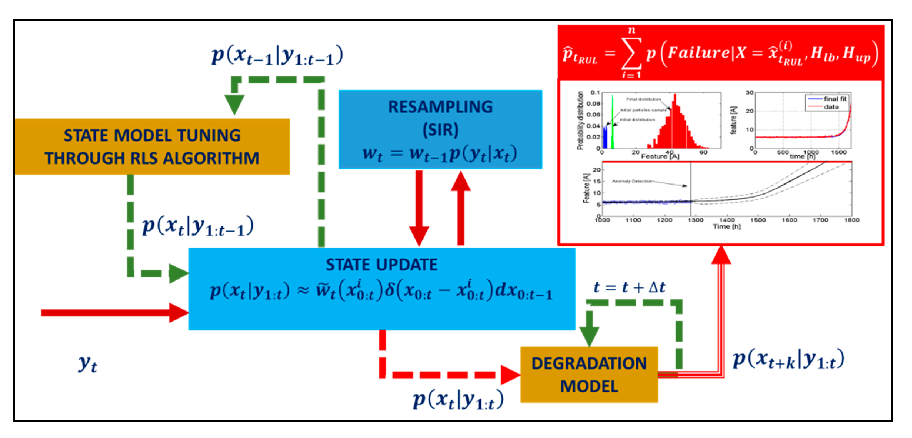
The prognostic algorithm makes use of a particle filtering scheme to infer the fault severity and forecast the degradation growth [25]. The particle filter scheme tracks the fault progression by iterating at each time stamp two consequential steps, the first being the “prediction” stage and the latter being the “filtering”. The prediction step combines the knowledge of the previous state estimate p ( x t | y t 1 ) with a process model p ( x 0 : t 1 | y 1 : t 1 ) to generate the a-priori estimate of the state probability density functions for the next time instant:
p ( x 0 : t | y 1 : t 1 ) = p ( x t | y t 1 ) p ( x 0 : t 1 | y 1 : t 1 ) d x 0 : t 1
This expression usually cannot be analytically solved; sequential Monte Carlo algorithms can be used in combination with efficient sampling strategies for such purpose [26]. Particle filtering approximates the state probability density function through samples or “particles” characterized by discrete probability masses, or “weights”, as:
p ( x t | y 1 : t ) w ˜ t ( x 0 : t i ) δ ( x 0 : t x 0 : t i ) d x 0 : t 1
where x 0 : t i represents the state trajectory, thus the fault severity, while y 1 : t are the measurements up to time t. During the “filtering” stage, a re-sampling scheme is employed to update the state estimates by updating the particles weights. One of the most common version of this algorithm, the sequential importance re-sampling (SIR) particle filter [27], updates the states weights using the likelihood of y t as:
w t = w t 1 p ( y t | x t )
Although widely adopted within the PHM community due to its simplicity and relatively low computational requirements, it is worth mentioning that this resampling scheme has limitations in the description of the distribution tails, and that more advanced resampling schemes have been proposed [28]. Nevertheless, the investigated fault mode is not safety critical, and the SIR scheme was adopted. Long-term prediction of the fault evolution can be obtained by iterating the “prediction” stage, and are used to estimate the probability of failure in a system given a hazard zone that is defined via a probability density function with lower and upper bounds for the domain of the random variable [29]. Depicted in Figure 9, this approach is based on particle filtering schemes in which tunable degradation models are adopted as process models. These models are then used both to estimate the current a priori state of the system, p ( x t | y 1 : t 1 ) , and to perform the iterative steps necessary to achieve the prognosis p ( x t + k | y 1 : t ) . Auto-tuned models are required to describe and follow changes in the degradation process and to describe the process and measurement noise. For the case study under consideration the particle filter employs a non-linear process model y t = f ( x t ) + ν , derived by fitting the feature vs fault severity data set described in Section 4. The process noise ν is then obtained through a kernel function mirroring the feature distribution around the fitted model. The state model x t + 1 = f ( x t , t ) + σ is a time-dependent linear model which parameters are automatically tuned through a recursive least squares [30] algorithm operating over the state estimates provided by the particle filter itself. The measure noise σ is estimated at each time stamp computing the state estimate variance with respect to the noiseless output of the state model itself.
Other options to describe the state model, such as long-short memory networks (LSTMs) used by the authors in [31], were discarded to keep the required computational effort to a minimum and prepare an algorithm suitable for on-board activities. The particle filter code also employs the noise compensation techniques presented in [32] and used to avoid the overestimation of the features uncertainty propagation during the long-term prognosis. The output of the prognostic algorithm is represented as the RUL distribution for each prediction, coupled with the evaluation of the risk of failure as detailed in [29].

5.3. Performance Evaluation

To evaluate the performance of the proposed PHM scheme over the selected case study, an extensive simulation campaign spanning ten different actuators and more than 500 simulated flight hours was performed. Each simulated actuator was fed with a different flight history, and the parameters of the Archard’s law used to model the wear of the sealing elements were randomized for each EHSA around a common mean value to represent the variance of their physical and geometrical properties due the production and assembly processes.
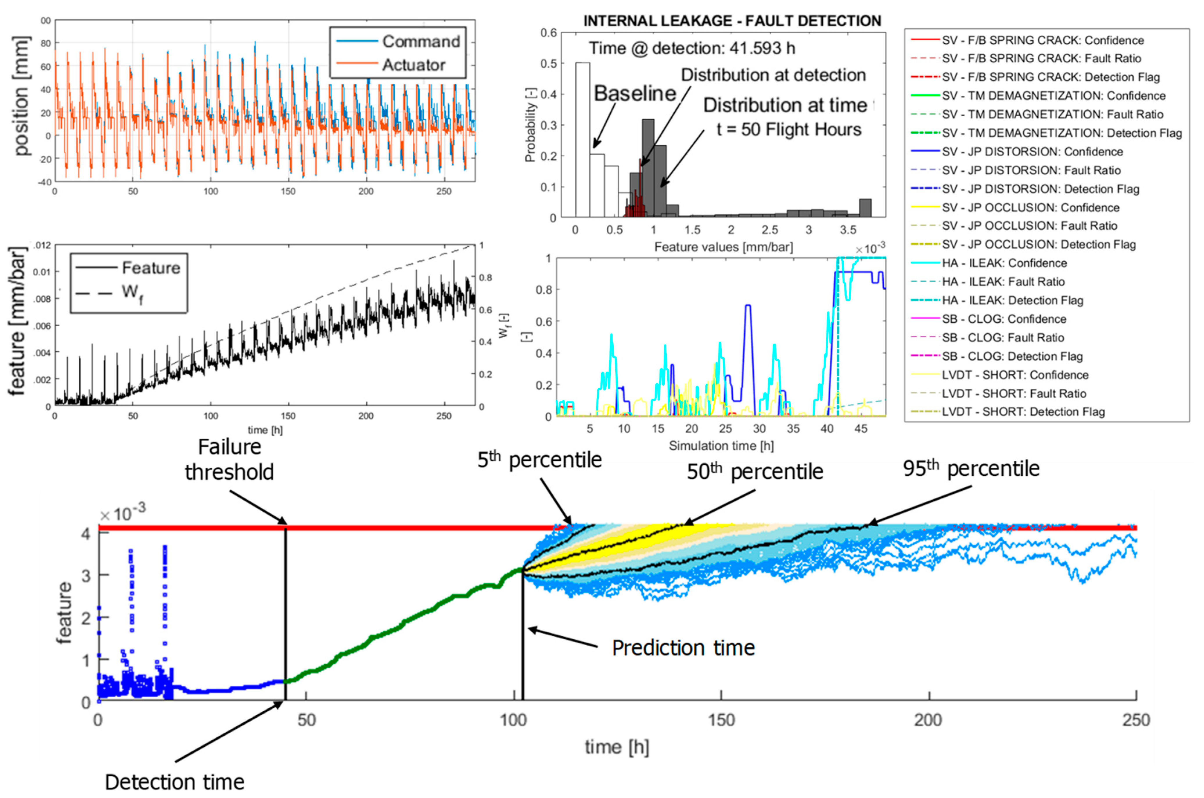
Since the considered aircraft is used on long-range routes, the duration of each flight is drawn randomly from a uniform distribution ranging between six and ten hours. Results are then analyzed and ranked according to the most common metrics for PHM algorithms, such as the prognostic horizon, the relative accuracy (RA) and the cumulative relative accuracy (CRA) [33]. An example of the results of the PHM framework is provided in Figure 10; in the top left diagrams, the feature behavior in time is depicted along the fault progression and the actuator response to the command sequence of the simulated flights. In the top right diagrams, the results of the fault detection algorithm are provided, while in the bottom graph we have reported an example of the prognostic forecast for a given prediction time.
Due to the on-going degradation the feature associated with the internal leakage growth tends to increase, leading to the fault declaration. Notice that the confidence associated with the declaration of an excessive null-bias, related to the occurrence of a mechanical distortion of the jet-pipe anchor, also raises but stops before reaching the threshold value for the alarm. Once that the classifier can identify the fault mode, the diagnostic information is sent to the prognostic algorithm. On average, the PHM framework was able to successfully detect and identify the presence of faults associated with a leakage of 3.03 L/min in presence of a 270 bar pressure drop. The prognostic routines fared well in both RA and CRA scores, averaging 88.2% and 86.1% respectively over the considered degradation patterns. Similarly, the prognostic horizon was of 44.6 flight hours on average.

6. Conclusions

This paper provides an advancement towards the definition of a comprehensive PHM system for electro-hydraulic servo actuators employed as primary flight control systems in aircraft, focusing on the detection and prognosis of one of the most common failure modes of these components, the occurrence of internal leakage. Such prognostic framework was prepared for the EHSAs of a wide-body commercial aircraft operating over long-range routes. At first the case study was presented, along with the details of both the dynamic model used to perform the required simulation campaigns and of the test bench employed for the experimental activities. Results of previous studies were used to perform the feature selection and inform the definition of the fault diagnosis/failure prognosis algorithm based on a particle filtering scheme with a Recursive Least Square subroutine to automatically tune the hidden state model. The activities confirmed that the selected feature, the reciprocal of the actuator pressure gain computed through the moving root mean square values of the pressure drop across the chamber and the servovalve spool displacement was suitable for prognostic activities, exhibiting a linear dependency on the occurring leakage. The proposed prognostic scheme was then applied to several simulated actuators, each with its own flight history, achieving high marks in the most used performance metrics, hence showing promise towards its implementation to real in-flight data. It must be observed that results are still preliminary, and that an extensive verification of the proposed algorithm through in-flight data, possibly provided by airliners, must be performed before providing any final assessment on its applicability to in-service aircrafts.

Author Contributions

Conceptualization, A.D.M. and G.J.; methodology, A.D.M. and G.J.; software, A.C.B. and A.D.M.; validation, A.D.M. and G.J., formal analysis, A.D.M.; investigation, A.C.B. and A.D.M.; data curation, A.C.B. and A.D.M.; writing—original draft preparation, A.D.M.; writing—review and editing, A.C.B., G.J. and M.S.; supervision, G.J. and M.S.; project administration, G.J. and M.S., funding acquisition, G.J. All authors have read and agreed to the published version of the manuscript.

Funding

This research received no external funding.

Data Availability Statement

Datasets employed in this paper belongs to Collins Aerospace and are not publicly available.

Acknowledgments

Experimental tests have been performed at Collins Aerospace facilities in Saint-Ouen-l’Aumône, France.

Conflicts of Interest

Authors declares no conflict of interest.

Appendix A

Table A1. Acronym list.
AcronymMeaning
ANNArtificial Neural Network
C-BITContinuous Built-In Test
CRACumulative Relative Accuracy
EHSAElectro-Hydraulic Servo Actuator
FMECAFailure Mode, Effects, and Criticality Analysis
I-BITInterruptive Built-In Test
LVDTLinear Variable Differential Transducer
P-BITPreflight Built-In Test
PHMPrognostics and Health Management
RARelative Accuracy
RULRemaining Useful Life
SVMSupport Vector Machine

References

  1. International Air Transport Association (IATA). Airline Maintenance Cost Executive Commentary an Exclusive Benchmark Analysis (FY2009 Data) by IATA’s Maintenance Cost Task Force. 2011. Available online: https://www.dea.univr.it/documenti/Avviso/all/all698615.pdf (accessed on 29 July 2021).
  2. Marla, L.; Vaaben, B.; Barnhart, C. Integrated Disruption Management and Flight Planning to Trade Off Delays and Fuel Burn. Transport. Sci. 2017, 51, 88–111. [Google Scholar] [CrossRef] [Green Version]
  3. Brown, D.W.; Georgoulas, G.; Bole, B.M. Prognostics Enhanced Reconfigurable Control of Electro-Mechanical Actuators. In Proceedings of the Annual Conference of the Prognostics and Health Management Society, San Diego, CA, USA, 27 September–1 October 2009. [Google Scholar]
  4. Bertolino, A.C.; Jacazio, G.; Mauro, S.; Sorli, M. Investigation on the ball screws no-load drag torque in presence of lubrication through MBD simulations. Mech. Mach. Theory 2021, 161, 104328. [Google Scholar] [CrossRef]
  5. Byington, C.S.; Watson, M.; Edwards, D. Data-driven neural network methodology to remaining life predictions for aircraft actuator components. IEEE Aerosp. Conf. Proc. 2004, 6, 3581–3589. [Google Scholar] [CrossRef]
  6. Guo, R.; Sui, J. Remaining Useful Life Prognostics for the Electro-Hydraulic Servo Actuator Using Hellinger Distance-Based Particle Filter. IEEE Trans. Instrum. Meas. 2019, 69, 1148–1158. [Google Scholar] [CrossRef]
  7. Chen, Y.; Mo, Z.; Xie, L.; Miao, Q. Fault Detection and Diagnosis of Aircraft Electro Hydrostatic Actuator Control System. In Proceedings of the 2018 Prognostics and System Health Management Conference, Chongqing, China, 26–28 October 2019. [Google Scholar]
  8. Li, L.; Huang, Y.; Tao, J.; Liu, C.; Li, K. Featured temporal segmentation method and AdaBoost-BP detector for internal leakage evaluation of a hydraulic cylinder. Meas. J. Int. Meas. Confed. 2018, 130, 279–289. [Google Scholar] [CrossRef]
  9. Autin, S.; Socheleau, J.; Dellacasa, A.; De Martin, A.; Jacazio, G.; Vachtsevanos, G. Feasibility Study of a PHM System for Electro-hydraulic Servo- actuators for Primary Flight Controls. In Proceedings of the Annual Conference of the Prognostic and Health Management Society, Philadelphia, PA, USA, 24–27 September 2018; pp. 1–19. [Google Scholar]
  10. Autin, S.; De Martin, A.; Jacazio, G.; Socheleau, J.; Vachtsevanos, G.J. Results of a feasibility study of a Prognostic System for Electro-Hydraulic Flight Control Actuators. Int. J. Progn. Heal. Manag. 2021, 12. [Google Scholar] [CrossRef]
  11. De Martin, A.; Jacazio, G.; Nesci, A.; Sorli, M. In-depth Feature Selection for PHM System’s Feasibility Study for Helicopters’ Main and Tail Rotor Actuators. In Proceedings of the European Conference of the Prognostics and Health Management Society, PHME2020. Turin, Italy, 27–31 July 2020; pp. 1–9. [Google Scholar]
  12. Nesci, A.; De Martin, A.; Jacazio, G.; Sorli, M. Detection and Prognosis of Propagating Faults in Flight Control Actuators for Helicopters. Aerospace 2020, 7, 20. [Google Scholar] [CrossRef] [Green Version]
  13. Vachtsevanos, G.; Lewis, F.; Roemer, M.; Hess, A.; Wu, B. Intelligent Fault Diagnosis and Prognosis for Engineering Systems; John Wiley & Sons, Inc.: Hoboken, NJ, USA, 2006; ISBN 9780470117842. [Google Scholar]
  14. De Martin, A.; Dellacasa, A.; Jacazio, G.; Sorli, M. High-Fidelity Model of Electro-Hydraulic Actuators for Primary Flight Control Systems. In Proceedings of the BATH/ASME 2018 Symposium on Fluid Power and Motion Control, Bath, UK, 12–14 September 2018. [Google Scholar]
  15. Urata, E. On the torque generated in a servo valve torque motor using permanent magnets. Proc. Inst. Mech. Eng. Part C J. Mech. Eng. Sci. 2007, 221, 519–525. [Google Scholar] [CrossRef]
  16. Urata, E. Influence of unequal air-gap thickness in servo valve torque motors. Proc. Inst. Mech. Eng. Part C J. Mech. Eng. Sci. 2007, 221, 1287–1297. [Google Scholar] [CrossRef]
  17. Urata, E.; Suzuki, K. Stiffness of the elastic system in a servo-valve torque motor. Proc. Inst. Mech. Eng. Part C J. Mech. Eng. Sci. 2011, 225, 1963–1972. [Google Scholar] [CrossRef]
  18. Bertolino, A.C.; Gentile, R.; Jacazio, G.; Marino, F.; Sorli, M. EHSA primary flight controls seals wear degradation model. In Proceedings of the ASME International Mechanical Engineering Congress and Exposition, Proceedings (IMECE), Pittsburgh, PA, USA, 9–15 November 2018. [Google Scholar]
  19. Jelali, M.; Kroll, A. Hydraulic Servo-Systems; Springer: Berlin/Heidelberg, Germany, 2003; ISBN 978-1-4471-1123-8. [Google Scholar]
  20. Jacazio, G.; De Martin, A. Influence of rotor profile geometry on the performance of an original low-pressure gerotor pump. Mech. Mach. Theory 2016, 100, 296–312. [Google Scholar] [CrossRef]
  21. Stachowiak, G.W.; Batchelor, A.W. Engineering Tribology, 4th ed.; Elsevier: Amsterdam, The Netherlands, 2014; ISBN 9780123970473. [Google Scholar]
  22. ARCHARD, J. Basic lubrication theory A. Cameron Longmans. In Tribology; Longman: London, UK, 1971. [Google Scholar] [CrossRef]
  23. Jacobson, M.Z. Fundamentals of Atmospheric Modeling, 2nd ed.; Cambridge University Press: Cambridge, UK, 2005; ISBN 9781139165389. [Google Scholar]
  24. De Martin, A.; Jacazio, G.; Vachtsevanos, G. Windings fault detection and prognosis in electro-mechanical flight control actuators operating in active-active configuration. Int. J. Progn. Heal. Manag. 2017, 8. [Google Scholar] [CrossRef]
  25. Orchard, M.E.; Vachtsevanos, G.J. A particle-filtering approach for on-line fault diagnosis and failure prognosis. Trans. Inst. Meas. Control 2009, 31, 221–246. [Google Scholar] [CrossRef]
  26. Roemer, M.J.; Byington, C.S.; Kacprzynski, G.J.; Vachtsevanos, G.; Goebel, K. Prognostics. In System Health Management: With Aerospace Applications; John Wiley & Sons: Hoboken, NJ, USA, 2011; ISBN 9780470741337. [Google Scholar]
  27. Arulampalam, M.S.; Maskell, S.; Gordon, N.; Clapp, T. A tutorial on particle filters for online nonlinear/nongaussian bayesian tracking. In Bayesian Bounds for Parameter Estimation and Nonlinear Filtering/Tracking; IEEE: New York, NY, USA, 2007; ISBN 9780470544198. [Google Scholar]
  28. Acuña, D.E.; Orchard, M.E. Particle-filtering-based failure prognosis via sigma-points: Application to Lithium-Ion battery State-of-Charge monitoring. Mech. Syst. Signal Process. 2017, 85, 827–848. [Google Scholar] [CrossRef]
  29. Acuña, D.E.; Orchard, M.E. A theoretically rigorous approach to failure prognosis. In Proceedings of the 10th Annual Conference of the Prognostics and Health Management Society 2018 (PHM18), Philadelphia, PA, USA, 24–27 September 2018. [Google Scholar]
  30. Bishop, C.M. Pattern Recoginiton and Machine Learning; Springer: Berlin, Germany, 2006; ISBN 978-0-387-31073-2. [Google Scholar]
  31. Grosso, L.A.; De Martin, A.; Jacazio, G.; Sorli, M. Development of data-driven PHM solutions for robot hemming in automotive production lines. Int. J. Progn. Heal. Manag. 2020, 11. [Google Scholar] [CrossRef]
  32. De Martin, A.; Jacazio, G.; Sorli, M. Enhanced Particle Filter framework for improved prognosis of electro-mechanical flight controls actuators. In Proceedings of the PHM Society European Conference, Utrecht, The Netherlands, 3–6 July 2018; Volume 4. [Google Scholar]
  33. Saxena, A.; Celaya, J.; Balaban, E.; Goebel, K.; Saha, B.; Saha, S.; Schwabacher, M. Metrics for evaluating performance of prognostic techniques. In Proceedings of the 2008 International Conference on Prognostics and Health Management, PHM 2008, Denver, CO, USA, 6–9 October 2008. [Google Scholar]
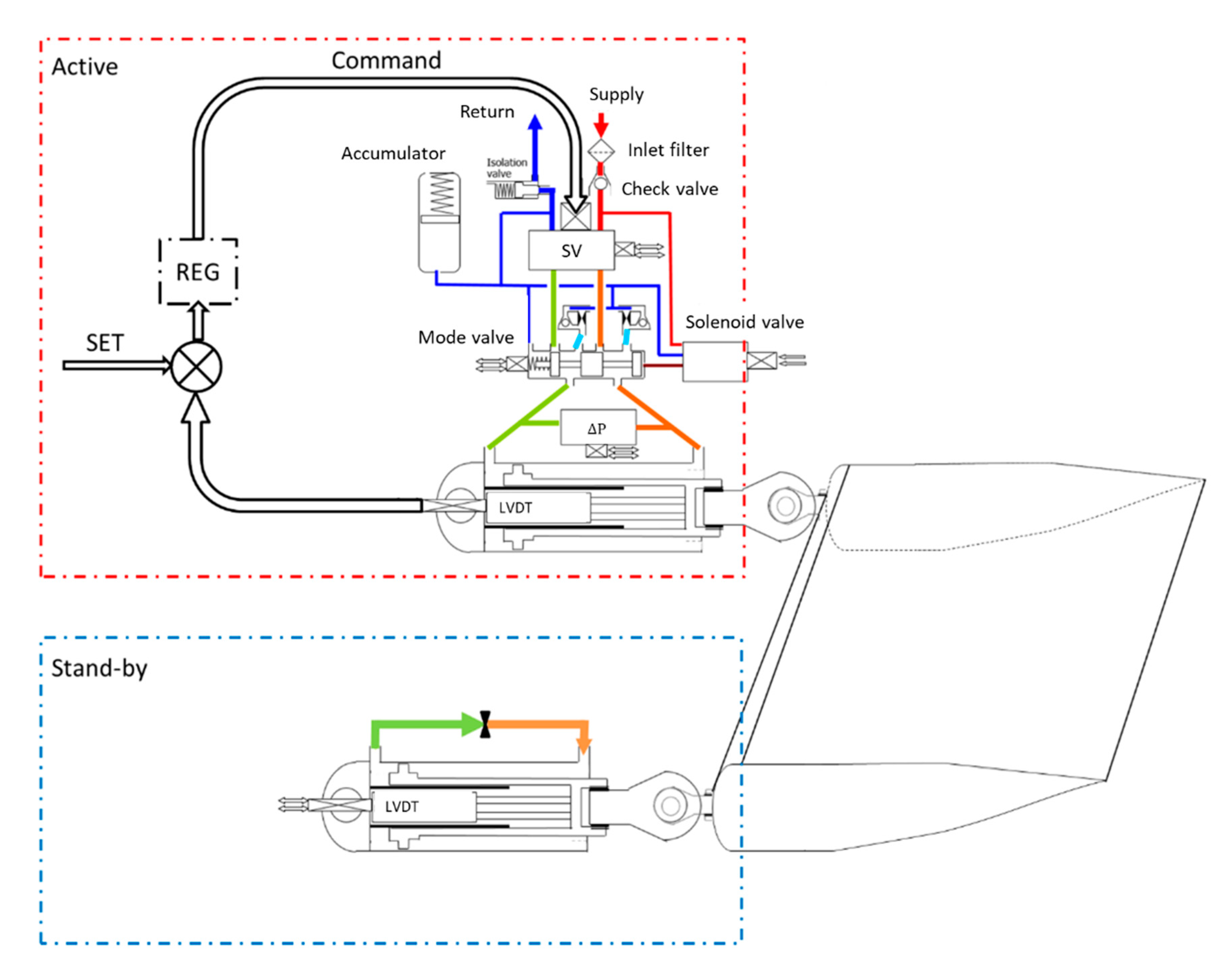
Figure 1. Architecture of the considered case-study.
Actuators 10 00215 g001
Figure 2. Schematics and modeling of a jet-pipe servovalve.
Actuators 10 00215 g002
Figure 3. Overview of the actuator model.
Actuators 10 00215 g003
Figure 4. The experimental set-up.
Actuators 10 00215 g004
Figure 5. Features behavior on simulated dataset.
Actuators 10 00215 g005
Figure 6. Results of the experimental campaign.
Actuators 10 00215 g006
Figure 7. Feature behavior for increasing internal leakage.
Actuators 10 00215 g007
Figure 8. The PHM framework.
Actuators 10 00215 g008
Figure 9. Flowchart of the prognostic algorithm.
Actuators 10 00215 g009
Figure 10. Output of the prognostic routine.
Actuators 10 00215 g010
Table 1. Selected features.
Failure ModeSymbolFeature
Mechanical faults in the feedback spring of the servovalve f S V f b x s v R M S i s v R M S
Degraded permanent magnets in the first stage of the servovalve f S V t m i s v R M S x s v R M S
Jet pipe distortion f S V j p d | l | ¯ i m a x
Jet pipe channel blockage f S V j p o f ( x s v R M S , i s v R M S )
Short between LVDT windings f L V D T f ( V 1 , V 2 )
Internal leakage within the EHSA f H A L e a k x s v R M S Δ P R M S | x ˙ x ˙ t h r
Blockage of the by-pass channel in the stand-by actuator f H A s b f ( x ˙ s b y , Δ P s b y )
Publisher’s Note: MDPI stays neutral with regard to jurisdictional claims in published maps and institutional affiliations.