1. Introduction
Direct current (DC) motors are often used in transport robots, which have a number of disadvantages: low reliability, high cost, and sparking in the collector-brush node, which creates interference to electronic devices. Therefore, asynchronous motors are promising for the use as traction drives.
It is known that more than 60% of all electricity produced in the world is consumed by electric drives, and most of them are electric drives of general industrial mechanisms (pumps, fans, compressors, conveyors, etc.), as well as electric drives of various technological plants, not requiring deep regulation and high-speed operation and originally equipped with alternating current (AC) motors [
1].
The use of DC motors, which have favorable regulating characteristics and allow a relatively simple construction of the control system, as a rule, is limited by disproportionately high operating costs, low reliability and inability to operate in explosive, polluted and aggressive environments.
For these reasons, there is an active transition to the use of speed-controlled alternating current drives. This is due primarily to the development of element base: microprocessors and fully controlled power electronics [
2].
Frequency control of angular velocity is economical because the motor is controlled at low slips. Frequency control of angular velocity is usually smooth. However, it requires a quite complex converter. A great advantage of frequency control is the ability to realize high control properties, not inferior to a direct current drive. The electric drive with an asynchronous motor with squirrel-cage rotor is the simplest, most reliable and cheapest electric motor. Thus, we can conclude that a frequency-controlled squirrel-cage induction motor (IM) is the most suitable for a transport robot.
For the design of digital frequency-controlled actuators, high-precision but relatively complex continuous structural models are mostly used [
3].
The issues of algorithms synthesis of the functioning of digital electric drives with autonomous voltage inverter-IM are considered in detail in [
4,
5]. Alongside the structural models mentioned above, in the practice of algorithms synthesis of the functioning of actuators with autonomous voltage inverter-IM in their research and design, more simple and clear continuous models [
6,
7] are used both for scalar and vector control.
The development of IM control theory can be divided into two directions: variants of scalar control and variants of field-oriented control (FOC). An indisputable advantage of the second direction is the high quality of control, both in transient and steady-state modes. Many authors have paid their attention to the improvement of control methods [
8,
9,
10].
The purpose of the study is to improve the accuracy of IM control when the load changes by optimizing the PID controller for a given load. The novelty of the work is that the PID controller coefficients are automatically adjusted when the weight of the transport robot changes.
Simulation of the PID controller was performed in the SimInTech program. SimInTech (Simulation In Technic) is an environment for dynamic simulation of technical systems, designed for computational verification of control systems of complex technical objects. SimInTech performs simulation of objects with simultaneous simulation of the control system. It allows increasing the quality of control system design by checking the decisions made at any stage of the project. SimInTech is intended for detailed research and analysis of processes in automatic control systems, in tracking drives and robots, and in any technical systems. The description of the dynamics of objects should be presented as a system of differential-algebraic equations and/or realized by methods of structural modeling. The main uses of SimInTech are creation of models, design of control algorithms, their debugging on the object model, generation of C source code for programmable controllers.
The research [
11] proposes a control based on proportional derivative (PD) control with gravity compensation to show the robustness of this control scheme in the robotic arm’s industrial applications. The control algorithm is developed using a low-cost board like Raspberry Pi (RPI) where the robot operating system (ROS) is installed. The novelty of this approach is the development of new functions in ROS to make the PD control with gravity compensation in low-cost systems. The paper [
12] presents a general control framework for the constrained control of multibody systems actuated by vectorized thrusters. A cascade control scheme augmented with a constraint-enforcement unit is proposed to stabilize the system while ensuring constraint satisfaction at all times. The cascade controller consists of an inner loop and an outer loop that are interconnected by a suitable mapping. The inner loop is tasked to control the attitude of the vectorized thrusters. The outer loop is designed to steer the task configuration of the system to a desired pose, while providing to the inner loop the desired attitude through a mapping. The paper [
13] proposes the design of a hybrid iterative learning controller for a four-degrees-of-freedom (DOF) robotic machining manipulator (RMM). It combines a nonlinear saturated (sat) proportional + integral + derivative (PID) control with desired gravity compensation (dgc) and proportional + derivative (PD) based iterative learning control (ILC). The sat (PID) control is the primary component that maintains the local stability of the entire RMM system and the PDILC component provides robustness to parameter variations and uncertainties in the robot dynamics. Global asymptotic stability of the proposed control algorithm is conducted using Lyapunov direct method and LaSalles invariance principle.
An example of simulation using SimInTech [
14] trajectory of a water jet of a robotic fire monitor is considered in [
15]. A mathematical model of high-speed position pneumatic actuator of the executive movements of technological equipment is developed, and a computer model in SiminTech is developed in the paper [
16].
In the article computational experiments in SimInTech program for the adaptive regulator taking into account the cargo weight (from empty to maximum loaded) are carried out. The scheme of automatic selection of coefficients of PID drive controller considering the weight of cargo is proposed. The scheme of automatic selection of coefficients of PID regulator for electric drive taking into account the weight of cargo was proposed. The result of parametric synthesis of a discrete PID control the optimum values of its amplification coefficients have been determined.
2. Material and Methods
2.1. Calculation of Transport Robot Drive on Induction Motor
The parameters of the transport robot were given as follows:
Mass of the transport robot m = 2000 kg.
The maximal mass of the cargo m = 2000 kg.
Maximal velocity of movement VNOM = 1.5 m/s.
Maximal acceleration a = 0.4 m/s2.
Radius of running wheels r = 0.15 m.
The actuator of the transport robot in motion overcomes the moment of resistance (load), equivalent to the nominal torque of the actuator (the moments created by the forces of dry and viscous friction, in the kinematic elements of the drive were not considered) [
17,
18].
In accordance with the calculated power rating, we selected the induction motor AIR160M8 with the following parameters: P = 11 kW; U = 220 V; I = 26 A; n = 730 rpm; ω = 76.4 rad/s; J = 0.15 kg·m2.
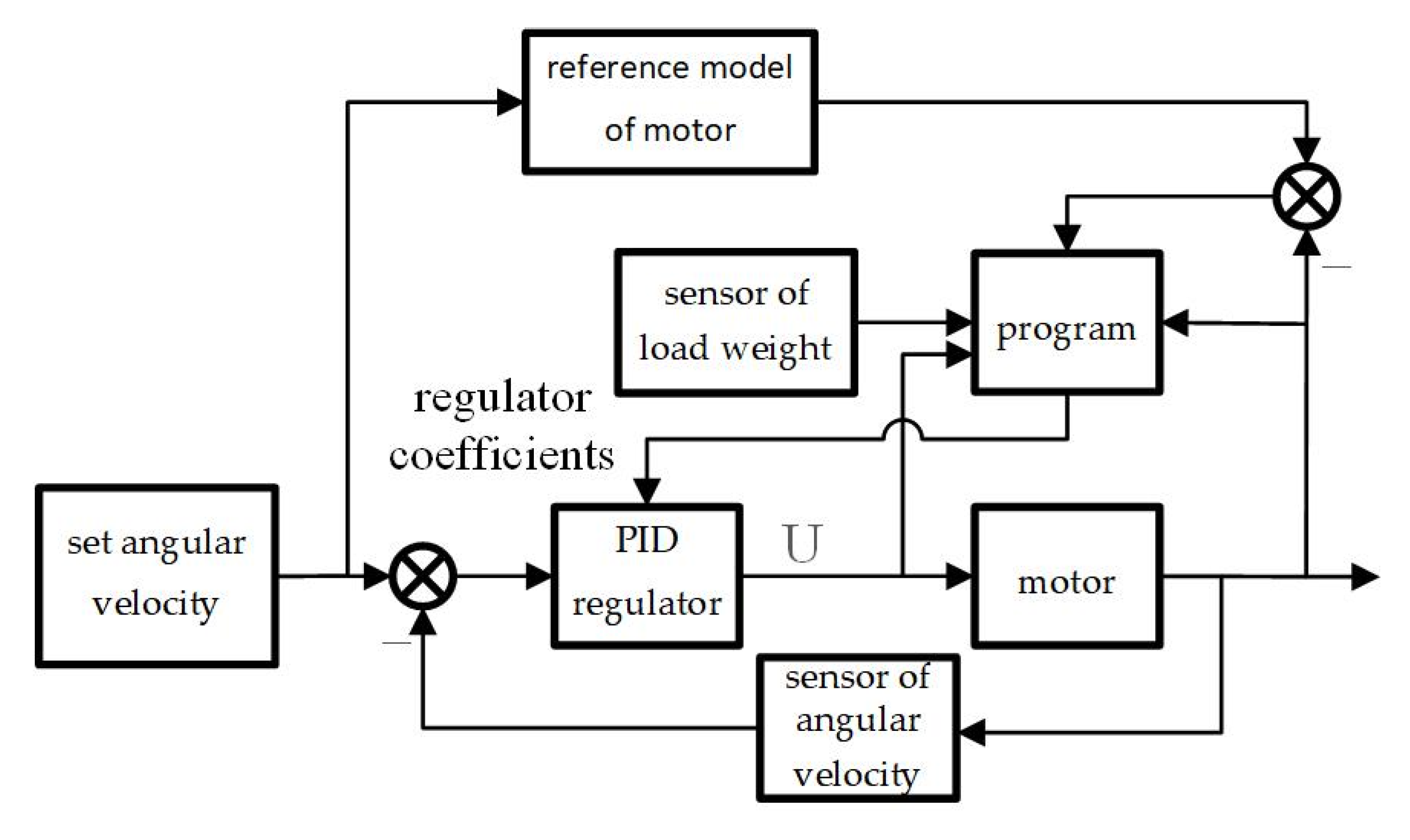
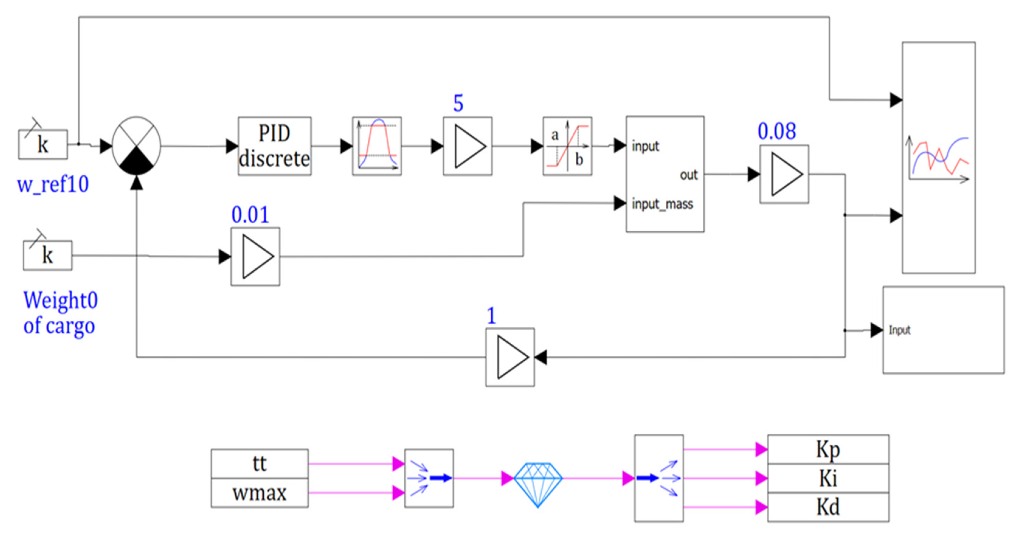
Depending on the weight of the robot, it was necessary to correct the optimal PID coefficients of the actuator. The structural diagram of the actuator with adjustment of the regulator coefficients is shown in
Figure 1.
Figure 1 shows the schematic diagram of IM with PID regulator, weight sensor, motor model and program for setting the regulator coefficients depending on the load weight.
Figure 2 shows the schematic diagram with IM, a worm reducer (R) to which the wheel (W) was attached and an angular velocity sensor (S), microcontroller with ADC and DAC.
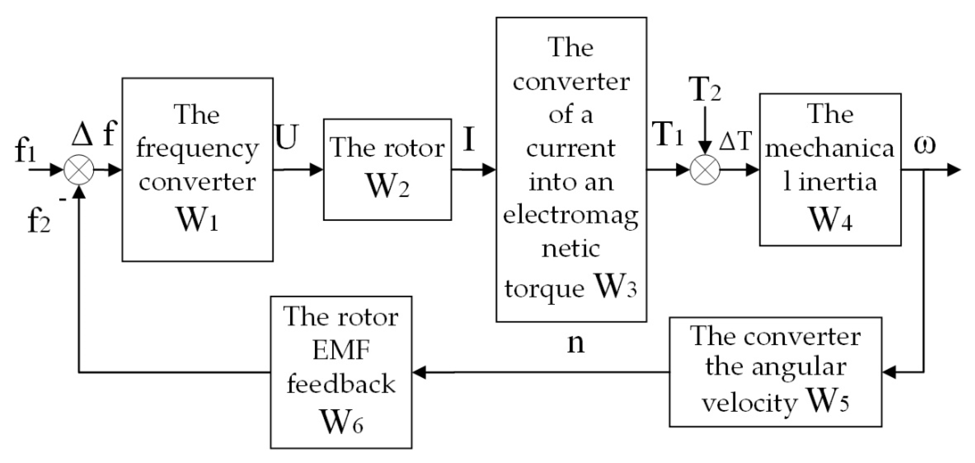
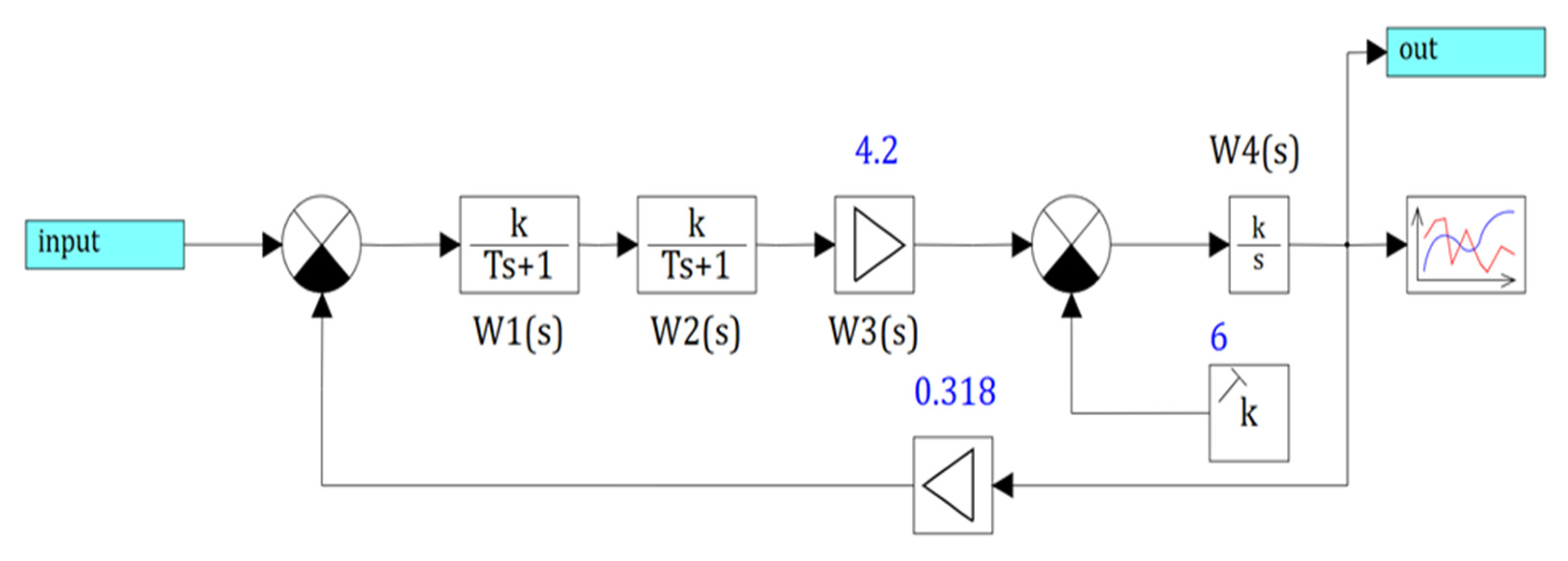
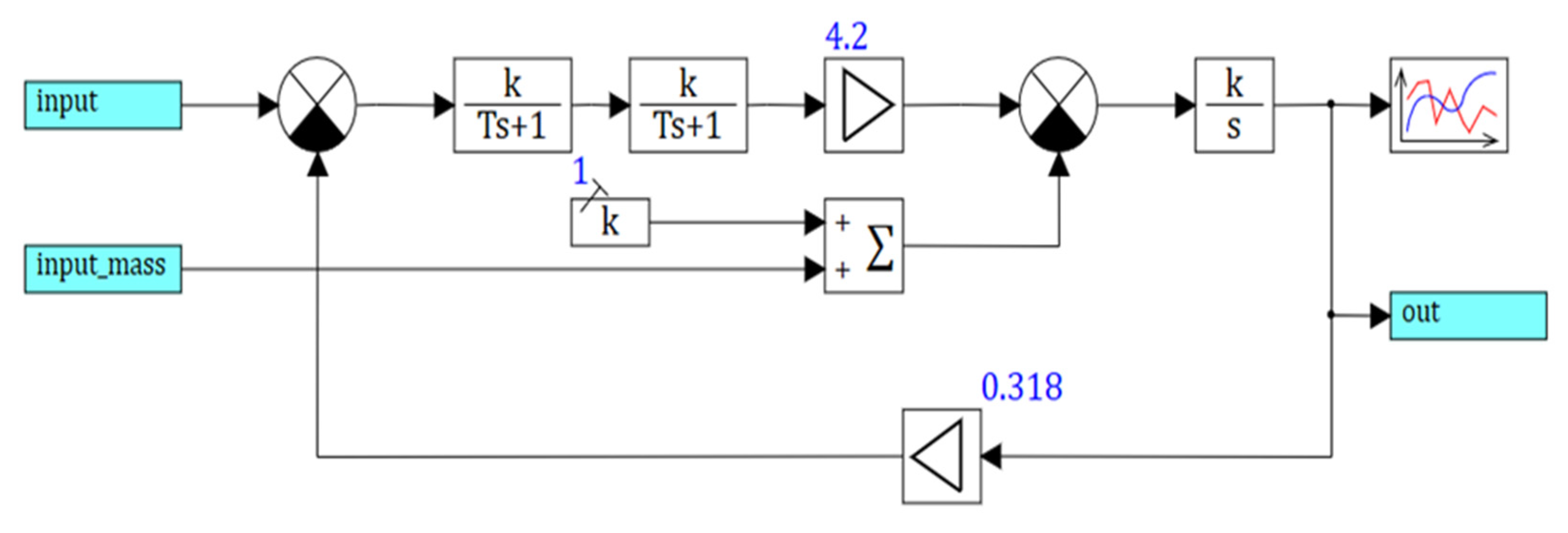
Figure 3 shows the transfer functions of the induction motor with the frequency converter (FC).
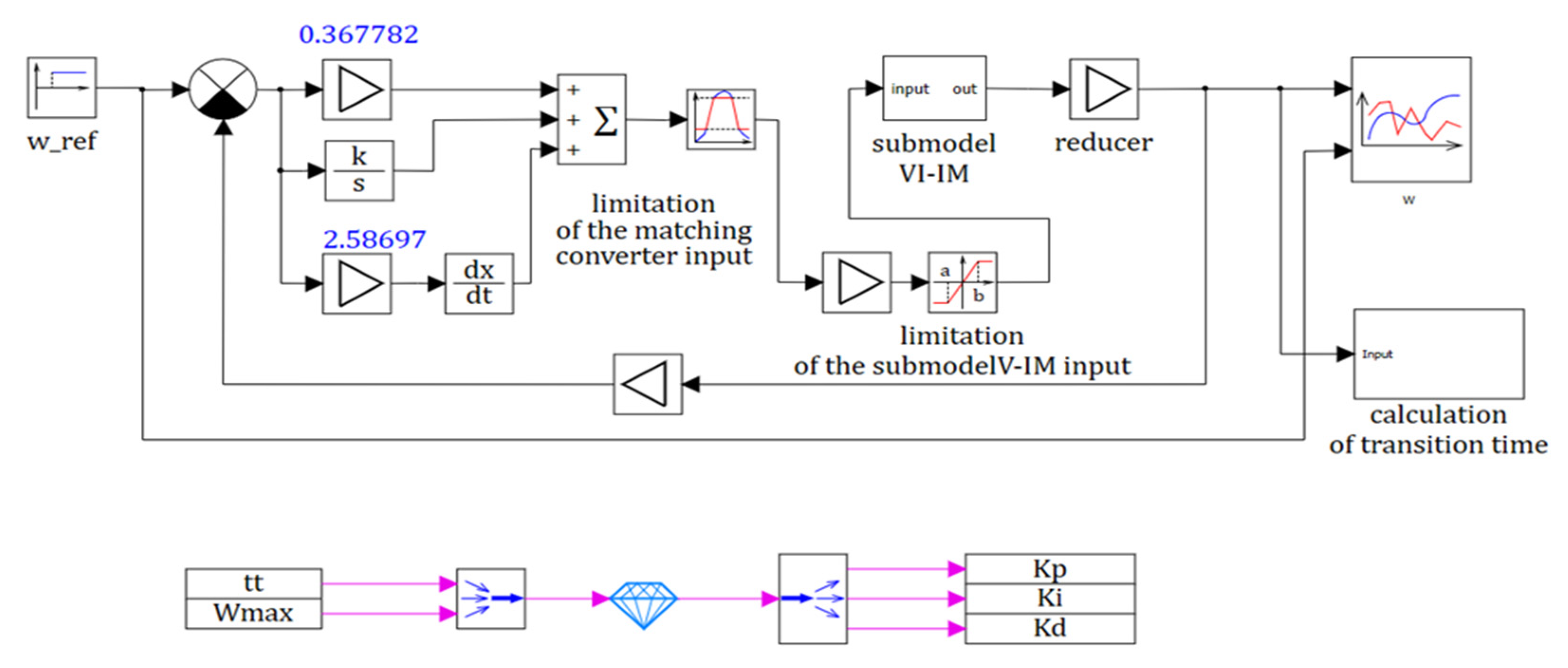
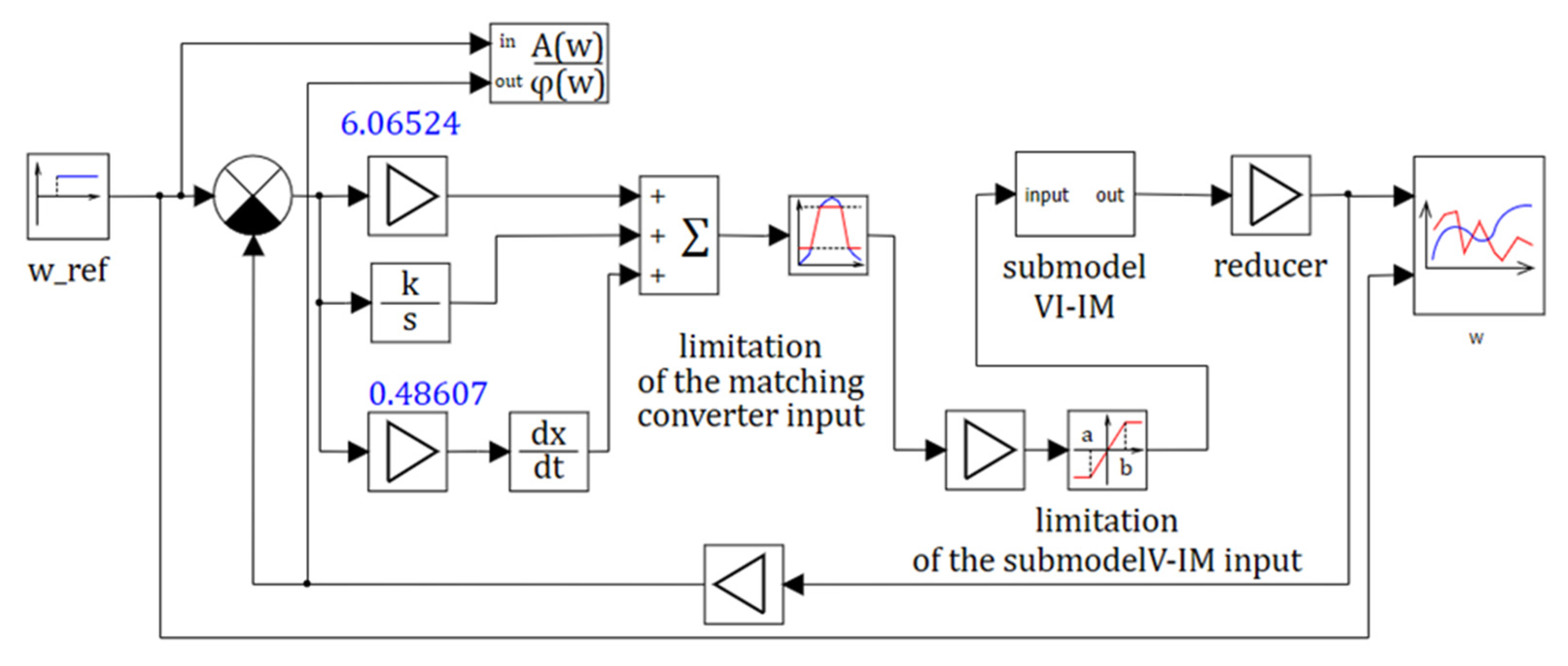
Figure 4 shows the induction motor model with PID controller in SimInTech program with an optimization block to tune its coefficients.
A schematic diagram of the actuator is shown in
Figure 2. It includes IM, a single-stage worm reducer (R) to which the wheel (W) was attached and an angular velocity sensor (S), the signal of which was fed to the ADC input. The motor was controlled by means of an autonomous voltage inverter (AVI) in accordance with the controller’s control algorithm by DAC output signal through the analogue potential input of AVI, which is represented in the scheme as a virtual matching converter (VMC). MCU is a microcontroller unit.
The motion module provided the control of the wheel rotation speed by means of the setting signal U, formed in the microcomputer of the upper level via software. Necessary information and parameters of the elements were included in the circuit (
Figure 2).
The driving module had an analogue potential DC input
Uin = 0–10 V with a direct proportional relationship between the input analogue signal and the output frequency [
19]. The power transmission of the motion module was a single-stage worm reducer with gear ratio
i = 8.
A microcontroller with the same bit ADC and DAC was used as a microcomputer. Maximum input voltage of ADC is U1max = ±5 V. Zero order extrapolator was used in DAC. The maximum value of the DAC output voltage U2max = ±5 V. Based on the above data, guided by the concept of “controller conversion”, the drive was calculated.
2.2. Formation of Continuous-Discrete and Continuous Structural Model of the Motion Module
The mathematical description of the structural model elements (
Figure 3) was as follows. Considering IM together with the frequency converter (FC) at scalar control as one link, its dynamic properties on the simplified model could be represented in the form of the block diagram, shown in
Figure 4.
The transfer functions of the links in the structural model in
Figure 3 were as follows.
The frequency converter had the transfer function:
where
is the transmission factor;
is the time constant of the frequency converter,
s;
U1 is the phase voltage (
U1 = 220 V); fc is the modulation carrier frequency of the frequency converter (
fc = 30 kHz).
The rotor of IM had the transfer function:
where
is a rotor transmission ratio,
;
is rotor time constant,
s;
R2 is resistance of rotor winding to stator winding in nominal mode (
R2 = 29.15 Ohm),
is inductance of stator winding due to leakage current in nominal mode (
= 0.0478 Hn),
is inductance of rotor winding to stator winding due to leakage current in nominal mode (
= 0.0619 Hn) [
20].
The constants
R2,
L1σ,
are the parameters of the T-substitution diagram of IM. Given the numerical values [
21]:
of the unit of the conversion of a current into an electromagnetic torque:
where
;
p is the number of pole pairs (
p = 2).
The unit, representing the mechanical inertia of the actuator, has the transfer function:
where
1/(kg·m
2) is the transfer coefficient of the unit.
where
J is the moment of the moving elements inertia of the robot reduced to the motor shaft;
JIM is the moment of inertia of IM (
JIM = 0.15 kg·m
2),
JR is the moment of inertia of the reducer together with the clutch (
JR = 0.2,
JIM = 0.2·0.15 = 0.03 kg·m
2),
JL is a total moment of inertia of a wheel (
JL = 0.008 kg·m
2), and
i is a gear ratio of the reducer (
i = 12.5).
In view of numerical values J = 0.18 kg·m2.
The unit which converts the angular velocity (rad/s) into speed (rpm):
where
;
The unit which represented the effect of the IM rotor EMF feedback has a transfer function:
where
;
The value of the load torque
TL:
where
Pn is rated motor power (
Pn = 11 kW),
ωn is rated motor speed (
ωn = 76.4 rad/s).
Numerical values adopted for each transfer function model come from direct calculations. Numerical values of transfer functions coefficients
W1(
s)…
W6(
s) are shown in
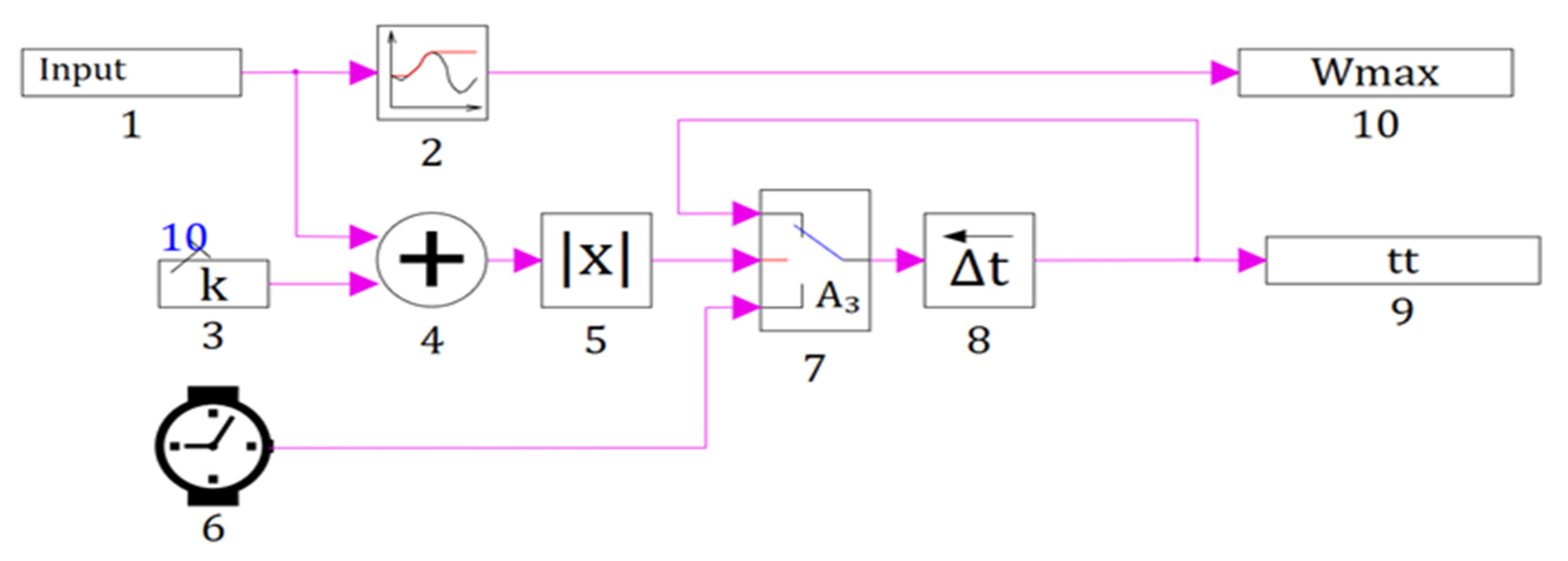
Table 1. Schematic window with the transient time calculation block open shown in
Figure 5.
The virtual matching transducer is represented as a proportional unit with a transfer function:
where
fmax.an is the maximum frequency of the analogue input of the stand-alone voltage inverter (VI) (
fmax.an = 50 Hz);
Umax.an is the maximum voltage of the stand-alone voltage inverter analogue input (
Umax.an = 10 V);
ktr is transfer coefficient (
ktr = 5 Hz/V).
The dynamic properties of the gearbox were taken into account in determining the total moment of inertia
J applied to the motor shaft and, neglecting its elastic properties, could be interpreted by the transfer function of the proportional unit:
where
krd is the transmission ratio of the reducer.
The proportional unit also approximated the dynamic properties of the wheel speed sensor:
where
U1 is output voltage of the angular motion sensor;
ks is transfer coefficient of the angular velocity sensor (
Umax/ω
max = 10/10 = 1 V/(rad/s);
Umax, ω
max are maximum voltage and maximum angular velocity respective).
As an algorithmic block a typical ideal discrete PID control law is taken with the following transfer function:
where
T is quantization period;
kp,
ki, and
kd are transfer coefficients of proportional, integral, and differential components, the determination of optimum values of which is the goal.
2.3. Parametric Synthesis of PID Control Law Based on Continuous Motion Module Model
The following data and numerical values required for synthesis of PID control law were determined. Optimization parameters are the coefficients of the PID controller kP, kI, kD.
The following optimization criteria can be adopted for a stepped input
U0 (
Figure 4) with a 1% “tube” and
TEM =
TL.
The transient must be without overshoot, the regulated value ω = 10 ± 0.1 rad/s (at 1% “tube”), ωmax = 10.1 rad/s, ωmin = 9.9 rad/s;
The transient time (ttt = 0.9 s) was determined by the fact that the controlled variable ω enters the 1% “tube” area.
Such conditions must provide transfer of control system from a state ω = 0 at t = 0 to a state ω = 10 ± 0.1 rad/s at t = ttt = 0.9 s.
The starting values of the parameters to be optimized kP, kI, kD were set by a simple selection, initially assuming their values to be unite.
By performing similar operations and procedures using the model (
Figure 4) and transfer functions (1)–(10), a structural diagram (
Figure 6) for parametric synthesis of continuous PID control law taking into account signals ω
max,
kP,
kI,
kD, and
ttt; for the purpose of the best approximation of the initial continuous model to the real actuator limits of signals at the input of the block simulating a virtual matching transducer in the range from 0 to 10 V and at the input of VI-IM submodel in the range from 50 to 0 Hz were entered.
A parametric optimization process based on the model is started (
Figure 4) and the results were obtained. Schematic window with VI-IM submodel shown in
Figure 6.
Optimization is ensured by the special optimization unit “Optimizer” from the “Analysis and Optimization” tab of SimInTech program. The model in SimInTech is not calculated once in dynamics, but several times until the optimum result is obtained [
7].
Thus, as a result of parametrical optimization of the PID control law based on a continuous model of a mechatronic motion module with frequency control the optimum values of its gain were found: kp = 6.1; ki = 0.79; kd = 0.49 at which the overshooting was absent (ωmax = 10 rad) and transient time is ttt = 0.595 s, that was less its prescribed value of 0.9 s.
2.4. Evaluation of Adequacy of Optimized Continuous Motion Modulus Model
An evaluation of the adequacy of the optimized continuous actuator model to its continuous-discrete (digital) model is performed in the following sequence.
In order to determine the quantization period
T on the basis of the model (
Figure 6), a separately continuous structural model of the drive with optimal parameters of the PID control law was created to build the frequency response needed to determine frequency
ωn.
The model (
Figure 7) was started and after completion of calculation process of the frequency response based on the data the boundary (maximum) value of period of quantum
Tmax at which the adequacy of continuous model of the movement module to its continuous-discrete model should be kept was calculated:
Tmax = π/ω
max = 3.14/167 = 0.0188 s ≈ 0.02 s.
3. Results
To estimate the influence of the quantization period value on the adequacy of the continuous-discrete model of the motion module to its continuous counterpart with optimal values of parameters of the continuous PID-control law (
kp = 6.1;
ki = 0.79;
kd = 0.49) their comparative simulation was performed at
T = 0.02 s and several values of
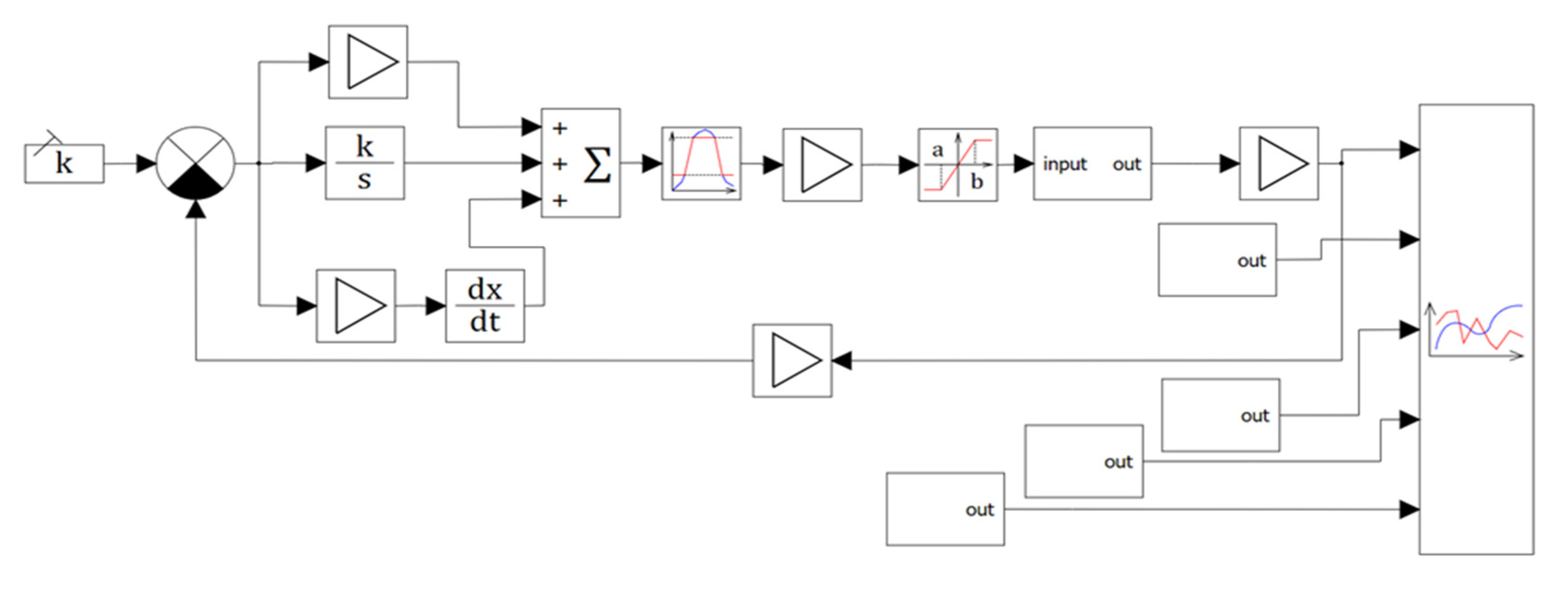
T > 0.02 s, using the structural scheme of simulation shown in
Figure 8, considering it together with
Figure 9.
The continuous-discrete model is based on
Figure 7 by replacing the blocks simulating a continuous PID control law with one Discrete PID block from the Discrete library.
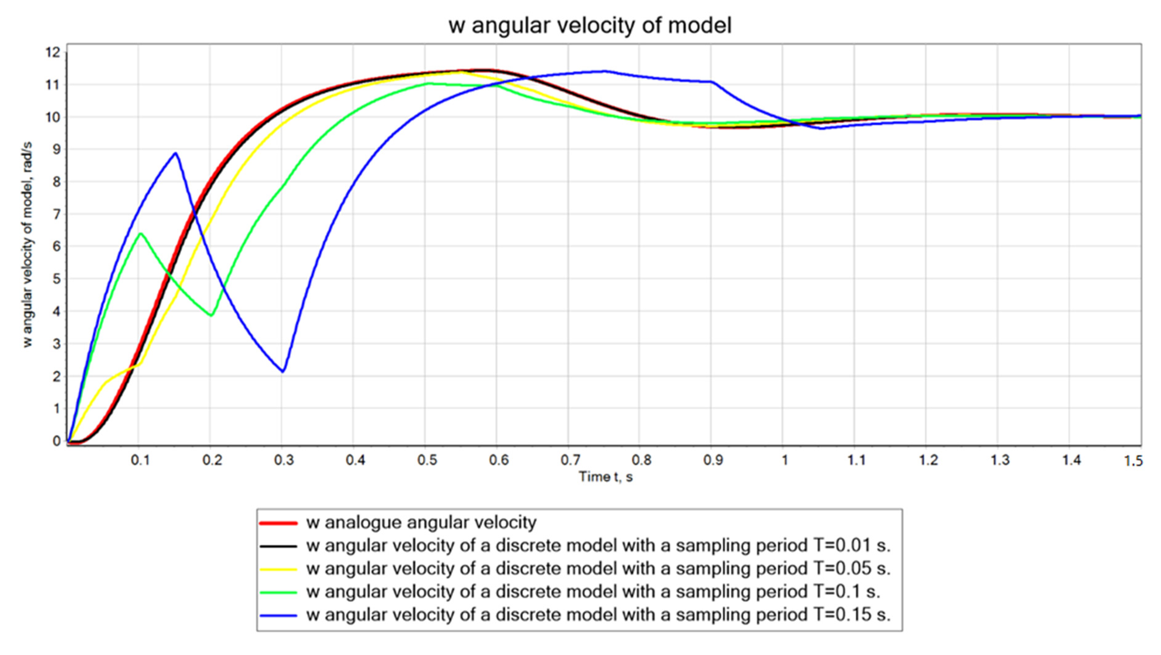
The results of the comparative simulation are displayed in
Figure 10. Their visual analysis indicates that the transient graphs (
Figure 10) 1–3 met the requirements for the given values of the optimization criteria, while graphs 4, 5 did not meet them. Therefore, at values of quantization period
T ≤ 0.05 s the continuous-discrete model of the motion module will be adequate to its continuous model. That allowed the controller to use a discrete PID-control law with a quantization period
T ≤ 0.05 s and optimal values of its parameters
kp = 6.1;
ki = 0.79;
kd = 0.49, determined as a result of the parametric synthesis of the continuous PID-control law. If it appeared that the RAM of the controller in use did not allow the quantization period
T ≤ 0.05 s to be executed, it would have to be increased taking into account the capacity of the RAM. In such a case, the mutual adequacy of the continuous and continuous-discrete models of the motion module was violated and then, obviously, a parametric synthesis of the discrete control law at
T > 0.05 s would be required.
The results were compared with the classic PID controller for this motor. After optimization, the transient time was reduced from 0.9 s to 0.8 s.
