Article

Design and Experimental Validation of a Fuzzy Cascade Controller for a Zero-Power Permanent Magnetic Suspension System with Variable Flux Path Control

School of Mechanical Engineering, Shenyang University of Technology, Shenyang 110870, China
*
Author to whom correspondence should be addressed.
These authors contributed to the work equally and should be regarded as co-first authors.
Actuators 2021, 10(6), 118; https://doi.org/10.3390/act10060118
Submission received: 6 May 2021 / Revised: 29 May 2021 / Accepted: 1 June 2021 / Published: 3 June 2021
(This article belongs to the Section Control Systems)

Abstract

:
Magnetic suspension technology has been a promising method to achieve contactless movement, and its advantages are smooth motion, no wear, no noise and low maintenance. In previous studies, the suspension force was mainly controlled by the current in the coils, which can lead to energy loss. To solve the problem of energy loss, we have proposed a novel zero-power permanent magnetic suspension system with variable flux path control (ZPPMSS-VFPC); moreover, the interference suppression and response of the ZPPMSS-VFPC need to be further investigated. This paper aims to improve the robustness and decrease the response time for the ZPPMSS-VFPC; as a result, a fuzzy cascade controller composed of a fuzzy controller and a cascade controller is designed and applied, in which the investigated fuzzy cascade control methods include the position loop fuzzy cascade control (PLFCC) and angle loop fuzzy cascade control (ALFCC). The structure and the working principle of the proposed ZPPMSS-VFPC are introduced, and the theoretical modeling and the fuzzy cascade controller design of the system are exhibited. An experimental setup is established to validate the simulation results and to investigate the control effect of the designed controller. The experimental results demonstrate that the response times of the fuzzy cascade controller at the displacement disturbance and the force disturbance are 0.5 s and 0.6 s faster than those of the cascade control, respectively. Furthermore, the control effect of the PLFCC is better than that of the ALFCC. Overall, the fuzzy cascade controller not only has the characteristics of strong adaptability but also has the characteristics of easy adjustment parameters, which can be applied to the complex magnetic suspension system.

1. Introduction

Magnetic suspension is a popular technology that applies magnetic force to the target object to realize non-contact motion between objects. With the development of magnetic suspension technology, magnetic suspension technology has been widely applied to various fields, such as bearings [1,2], trains [3,4] and compressors [5]. Furthermore, magnetic suspension technology is also used in harvesting energy technology, in which the magnetic suspension wind turbine [6,7] uses the magnetic force to cause the blades of wind power generation to be suspended in the air gap, and the electrical energy generated by cutting magnetic induction lines is stored in the battery. Currently, magnetic suspension technology is developing rapidly, and mainly includes electromagnetic technology [8,9], permanent magnet (PM) technology [10,11] and hybrid magnet technology [12,13].
Compared with ordinary trains, the maglev train has the advantages of faster speed, less noise and less harm to the environment; hence, the magnetic force technology that is applied to the vehicle is widely studied by the researcher. Park et al. [14] investigated each factor that mutually affects the control of the maglev train using mathematical analysis and improved the operating efficiency by varying the slip frequency according to the operating conditions of the maglev train. Based on the model of the maglev train, the dynamic processes were established and analyzed by Chaban et al. [15], including the effect of the magnetic potential hole, and a system of ordinary differential equations of the dynamic state was presented in the normal Cauchy form. To present a fatigue strength evaluation method for the bogie frame of urban maglev, Han et al. [16] evaluated experimentally static strength for the bogie frame of an urban maglev train, in which the fatigue analysis, cumulative damage and fatigue test based on a developed fatigue load were the research objects. Zhou et al. [17] investigated the dynamic response of the levitation module for the urban maglev train in the presence of track irregularities and proposed an adaptive vibration control method to suppress the vibration of the rear levitation gap. Furthermore, an important application of magnetic suspension technology is the magnetic bearing field. Compared with the mechanical contact bearings, the advantages of the magnetic bearings are high speed, low noise, low wear and long service life. Spece et al. [18] improved the closed-loop performance of the magnetic bearing and analyzed the relationship between various parameters and the dynamic performance of the magnetic bearing. The linear offset-free model predictive control for an active magnetic bearing application was investigated by Bonfitto et al. [19], the modeling and design of the control architecture were given, and the experiment for one degree of freedom active magnetic bearing system was carried out. Schuhmann et al. [20] investigated the application of optimal state estimation and optimal state feedback algorithms for real-time active magnetic bearing control. However, there are some drawbacks in each traditional technology; the electromagnetic technology has the disadvantages of large volume and high calorific value, the drawbacks of the PM technology are that it is difficult to control and has low material strength, and the hybrid magnet technology also has the disadvantages of high calorific value and high energy consumption. Moreover, the PM technology has the advantages of small volume and low energy consumption. Therefore, to apply the advantages and solve the problems of the PM technology, a novel control method of the suspension force controlled by the magnetic flux path has been presented by Sun et al. [21,22], and the permanent magnetic suspension system with variable flux path control (PMSS-VFPC) was designed, which can be applied to the field of dust-free transmission. Moreover, on this basis, to eliminate the torque on the PM of the device and achieve the zero power suspension of the PMSS-VFPC, a novel zero-power permanent magnetic suspension system with variable flux path control (ZPPMSS-VFPC) was proposed [23], and the effects of the structure factors on the suspension force were analyzed [24].
Magnetic suspension systems have strong nonlinear and multiple disturbance performances; hence, the controller of the suspension system is an important research object. Mercado-Uribe et al. [25] designed a discontinuous integral controller applied to a magnetic suspension system to robustly track a time-varying reference and solved the problems of the time-varying perturbations and uncertainties of the system. The unbalanced forces and contact forces could affect the suspension force of the active magnetic bearing at the acute exogenous disturbance or external fault. Pesch et al. [26] proposed a novel robust control strategy for ensuring levitation recovery, and the proposed strategy utilized model-based μ-synthesis to find the requisite magnetic bearing control law. To solve the problem of a time-consuming iterative manual tuning procedure for PID controllers in the active magnetic bearings, a multiobjective genetic algorithm was introduced by Wei et al. [27], and the combination of frequency-and time-domain-based was optimized. In the disturbance research of magnetic levitation system, Wei et al. [28] proposed a time-varying active disturbance rejection solution, which can obtain a simple and practical solution that does not depend on the exact model information. Anantachaisilp et al. [29] analyzed the tradeoff between the simplicity of the controller structure and the performance of the closed-loop system for the active magnetic bearing and proposed the design of a fractional-order Proportional-Integral-Derivative controller to achieve the tradeoff. To verify the robustness of the ZPPMSS-VFPC under external disturbances, Zhou et al. [30] adopted the two controllers to investigate its suspension characteristics, in which the two controllers are a cascade PD controller and a parallel PD controller. The traditional PID controller has the advantages of simple structure, good stability, reliable operation and convenient adjustment. However, the proposed ZPPMSS-VFPC has the characteristics of strong nonlinear and strong interference; the traditional PID controller cannot adapt to the magnetic suspension systems, which can cause the system to overshoot greatly and can cause long response times.
Therefore, to obtain better dynamic performance and improve the control effect of the proposed novel ZPPMSS-VFPC, this paper designs a fuzzy cascade controller to investigate the dynamic performance of the magnetic suspension system. The designed fuzzy cascade controller consists of a fuzzy controller and a cascade controller; therefore, the control effect of the designed fuzzy cascade controller is better than that of the traditional PID controller, which has the characteristics of strong adaptability of fuzzy control and easy adjustment parameters of PID control. Thus, the content of this paper is organized as follows: Section 2 introduces the structure and working principle of the ZPPMSS-VFPC. In Section 3, the theoretical model and the fuzzy cascade controller are derived and designed, respectively. In Section 4, the control results of the two controllers on the system are obtained by the simulation. The experiments are carried out to verify the fuzzy cascade controllers in Section 5, and the comparison results between the fuzzy cascade controller and cascade controller are illustrated. The conclusion is presented in Section 6.

2. Structure and Working Principle
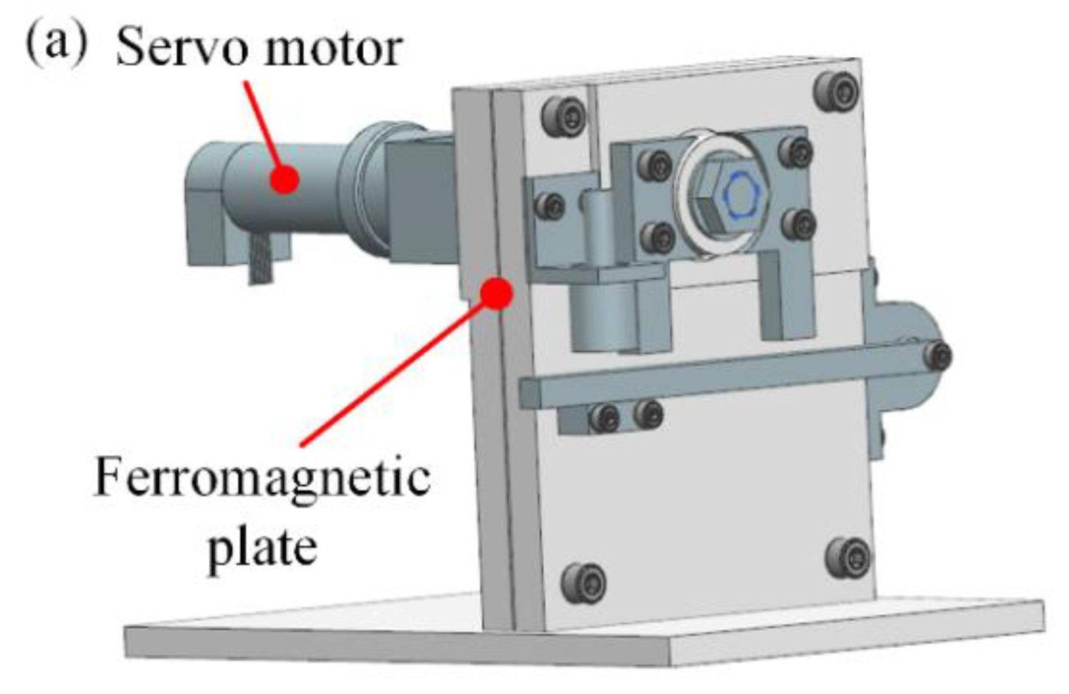
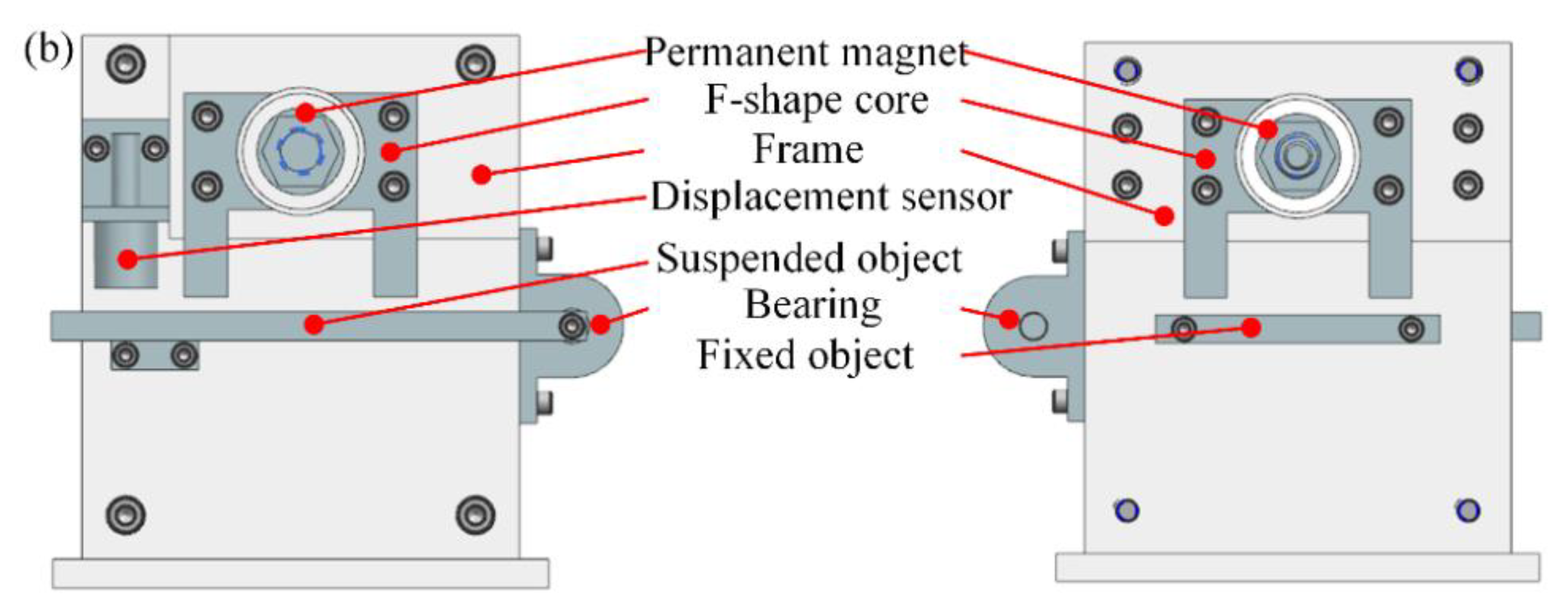
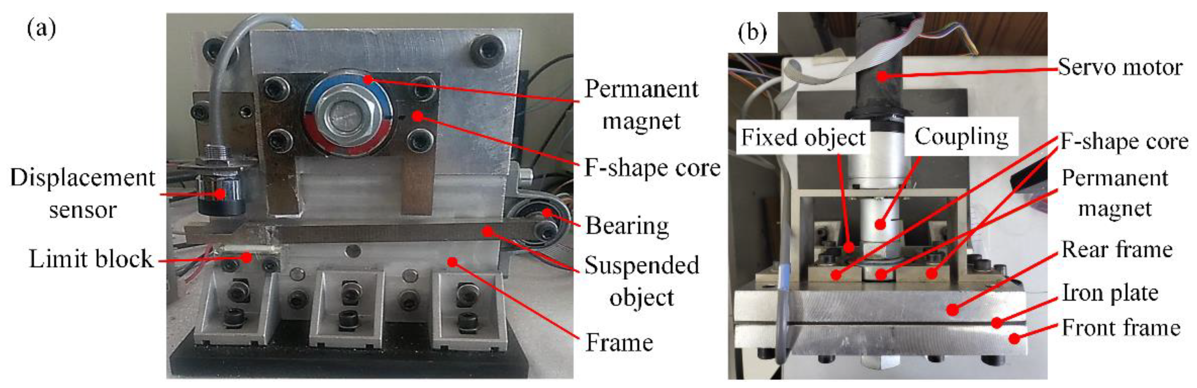
2.1. Structure

The proposed ZPPMSS-VFPC can realize the non-contact between the transportation device and the track. The 3D model of ZPPMSS-VFPC is illustrated, as shown in Figure 1a. It can be found that the device is driven by the servo motor, and there is a ferromagnetic plate between the frames, which is utilized to eliminate the effect between the two PMs. Figure 1b shows the structure of the zero-power permanent magnetic suspension device; it can be seen that the ZPPMSS-VFPC mainly consists of two PMs, four F-shape cores, a displacement sensor, a suspended object, a fixed object, frames and a bearing. The two PMs are connected with the servo motor using a coupling, and the F-shape cores and the displacement sensor are fixed on the frame. Furthermore, one PM, the suspended object and the two F-shape cores are mounted on the front of the frame, and the other PM, the fixed object and the two F-shape cores are symmetrically mounted on the back of the frame, in which the magnetic pole of two PMs is staggered 90 degrees. Meanwhile, the suspended object can move in a single degree of freedom through the coupling.

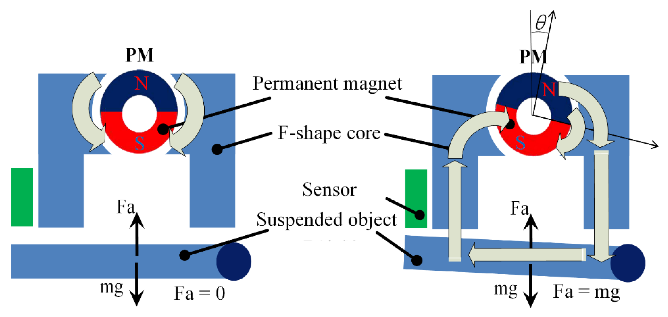
2.2. Working Principle

2.2.1. Suspension Principle

A schematic diagram of the suspension principle is illustrated in Figure 2; the suspension force of the system is changed by changing the rotation angle of the PM. When the rotation angle of the PM ring is zero, the magnetic flux starts from the N pole of the PM, passes through the F-shape core and returns to the S pole of the PM. Hence, there is no suspension force in the system. When the PM turns a certain angle, a part of the magnetic flux starts from the N pole of the PM ring, passes through the F-shape core, suspended object, and the other F-shape core, and returns to the S pole of the PM. Therefore, the F-shape core can generate the suspension force, and when the gravity of the suspended object is equal to the suspension force, the suspended object can be suspended. Overall, the suspension force is changed by changing the number of magnetic fluxes passing through the suspended object. The more magnetic flux passes through the suspended object, the greater the suspension force that can be generated.

2.2.2. Zero Power Principle

According to the analysis of Section 2.2.1, the suspended object can be suspended by the suspension force generated by the F-shape cores, and it can be seen from Figure 1 that the suspension force is directly transmitted to the frame through the F-shape cores mounted on the frame, and the PMs and the servo motor are not affected by the suspended object; therefore, the servo motor has no energy consumption in the stable suspension state. However, because of the unique structure of the F-shape core, there is the torque on the PM, which can make the device achieve the quasi zero power characteristics. Hence, the torque of the PM is eliminated by two PMs with poles 90 degrees apart in the proposed device, which can cause the suspension device to have zero power characteristics.

2.3. Novelty of the Proposed Magnetic Suspension Device

According to the introduced structure and working principle, the novelties of the proposed magnetic suspension device are the method of the magnetic force change and zero power characteristic. In the designed magnetic suspension device, the rotation angle of the permanent magnet can control the number of magnetic fluxes passing through the suspended object, which is used to change the magnetic force of the magnetic suspension system. Furthermore, the magnetic force provided by the F-shape cores is used to balance the gravity of the suspended object, and the F-shape cores are mounted on the frame. Hence, the permanent magnet and the motor are not affected by the gravity of the suspended object; the designed magnetic suspension device has the zero power characteristic.

3. Theoretical Modeling and Controller Design

3.1. Theoretical Modeling

The schematic diagram of the suspension system and related parameters is shown in Figure 3, in which the PM and the suspended object are rotated and swung, respectively.
According to Figure 3, the torque of the PM and the suspension force are given as follows,
τ i = k τ sin 2 θ d f i + Δ d τ
f m f i = k m sin 2 θ ( d f i + Δ d f ) 2
where i = 1 and 2 represents the left core and right core and rear core of the front structure, respectively; i = 3 represents the rear core of the device.
The torque borne from the PM is added to the motor shaft; hence, the total torque of the motor shaft is calculated,
τ = k τ sin 2 θ d f 1 + Δ d τ + k τ sin 2 θ d f 2 + Δ d τ + 2 k τ sin 2 ( θ + 90 0 ) d f 3 + Δ d τ
When the system is in the equilibrium position, the dynamic equations of the ZPPMS-VMFPS are obtained as follows:
J 1 θ ¨ = c 1 θ ˙ τ + k t i
J 2 ( d ˙ l 3 ) = c 2 d ˙ l 3 + f m f 1 l 2 + f m f 2 l 1 ( m g + F ) l l 2 cos α
Next, substituting Equations (2) and (3) into Equations (4) and (5), the dynamic equations are calculated:
J 1 θ ¨ = c 1 θ ˙ k τ sin 2 θ d f 1 + Δ d τ k τ sin 2 θ d f 2 + Δ d τ 2 k τ sin 2 ( θ + 90 0 ) d f 3 + Δ d τ + k t i
J 2 ( d ˙ l 3 ) = c 2 d ˙ l 3 + k m sin 2 θ ( d f 1 + Δ d f ) 2 l 2 + k m sin 2 θ ( d f 2 + Δ d f ) 2 l 1 ( m g + F ) l l 2 cos α
The controlled object is in a stable suspension state; applying Taylor theorem, the linearized equations in equilibrium position can be obtained:
J 1 Δ θ ¨ = c 1 Δ θ ˙ ( l 2 l 3 k τ sin 2 θ 0 ( d f 1 + Δ d τ ) 2 + l 1 l 3 k τ sin 2 θ 0 ( d f 2 + Δ d τ ) 2 ) Δ d ( 2 k τ cos 2 θ 0 d f 1 + Δ d τ + 2 k τ cos 2 θ 0 d f 2 + Δ d τ 4 k τ cos 2 θ 0 d f 3 + Δ d τ ) Δ θ + k t Δ i
J 2 Δ d ¨ = c 2 l 3 Δ d ˙ + ( l 2 k m sin 2 θ 0 ( d f 1 + Δ d f ) 2 + l 1 k m sin 2 θ 0 ( d f 2 + Δ d f ) 2 ) Δ θ + ( l 2 2 l 3 2 k m sin 2 θ 0 ( d f 1 + Δ d f ) 3 + l 1 2 l 3 2 k m sin 2 θ 0 ( d f 2 + Δ d f ) 3 ) Δ d F l l l 3 2 ( ( h 0 d 0 ) 2 + l 3 2 ) 1 2
where h 0 is the distance between the sensor and the suspended object in the horizontal position; θ 0 and d 0 are the angle and the distance between the sensor and the suspended object in the equilibrium position, respectively.
According to Equations (8) and (9), the state space equation of the system can be given:
x ˙ = A x + B 1 F + B 2 Δ i
And x = [ Δ θ Δ θ ˙ Δ d Δ d ˙ ] , A = [ 0 1 0 0 a 21 a 22 a 23 0 0 0 0 1 a 41 0 a 43 a 44 ] , B 1 = [ 0 0 0 b 14 ] , B 2 = [ 0 b 22 0 0 ] . where, a 21 = 1 J 1 ( 2 k τ cos 2 θ 0 d f 1 + Δ d τ + 2 k τ cos 2 θ 0 d f 2 + Δ d τ 4 k τ cos 2 θ 0 d f 3 + Δ d τ ) , a 22 = c 1 J 1 , a 23 = 1 J 1 ( l 2 l 3 k τ sin 2 θ 0 ( d f 1 + Δ d τ ) 2 + l 1 l 3 k τ sin 2 θ 0 ( d f 2 + Δ d τ ) 2 ) , a 41 = 1 J 2 ( l 2 k m sin 2 θ 0 ( d f 1 + Δ d f ) 2 + l 1 k m sin 2 θ 0 ( d f 2 + Δ d f ) 2 ) , a 43 = 1 J 2 ( l 2 2 l 3 2 k m sin 2 θ 0 ( d f 1 + Δ d f ) 3 + l 1 2 l 3 2 k m sin 2 θ 0 ( d f 2 + Δ d f ) 3 ) , a 44 = c 2 J 2 l 3 , b 14 = l l l 3 2 J 2 ( ( h 0 d 0 ) 2 + l 3 2 ) 1 2 , b 22 = k t J 1 .

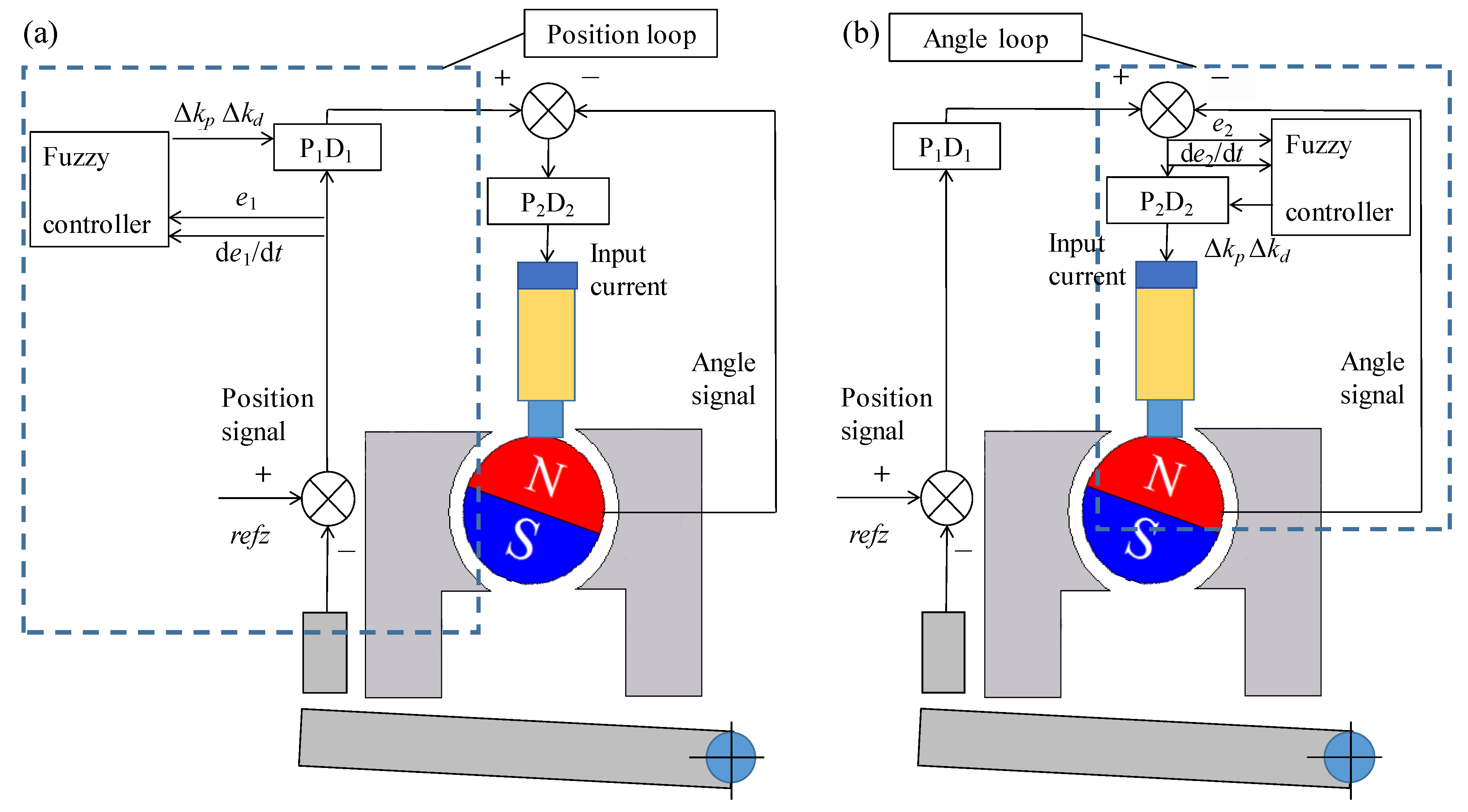
3.2. Controller Design

Based on the cascade control of the permanent magnetic system, the cascade controller consists of the position loop and angle loop; hence, two fuzzy cascade control methods are designed. In the position loop fuzzy cascade controller, the fuzzy rule is added to the position loop of the cascade control, and in the angle loop fuzzy cascade controller, the fuzzy rule is added to the angle loop of the cascade control. Therefore, it can be seen that the designed controllers not only have the characteristics of strong adaptability of fuzzy control but also have the characteristics of easy adjustment of cascade control. Figure 4a,b illustrate the position loop fuzzy cascade control (PLFCC) and the angle loop fuzzy cascade control (ALPCC), respectively.

3.2.1. Design of Domains and Membership Functions

Based on the traditional PID controller, the deviation e and change rate of deviation e c are used as the input of the PID controller, and the changes of the PID parameters Δ k p and Δ k d are used as the output of the PID controller. It can be seen from Figure 4a that the e 1 and e c 1 are the position deviation and change rate of position deviation, respectively, which are input to the fuzzy controller to modify the parameters of the P1D1 controller. In addition, Figure 4b shows that e 2 and e c 2 are the angle deviation and change rate of angle deviation, respectively, which are input to the fuzzy controller to modify the parameters of the P2D2 controller. Furthermore, the fuzzy subsets include negative big (NB), negative middle (NM), negative small (NS), zero (ZO), positive big (PB), positive middle (PM) and positive small (PS).
According to the above analysis, the domains of e 1 , e c 1 , e 2 and e c 2 are [−0.15, 0.15], [−6, 6], [−3, 3] and [−300, 300], respectively. Moreover, when the intersection membership value of the two adjacent curves of the membership function is small, the sensitivity of the controller is high. The output of the controller in the proposed permanent magnet suspension system is used to control the current of the motor, which can control the rotation angle of the permanent magnet, and the rotation angle of the permanent magnet is used to control the magnetic force of the system; hence, the suspension system needs a faster response speed and a high sensitivity controller. According to the above analysis, since the intersection membership value of the two adjacent curves of the triangle-shaped membership function is smaller than that of other membership functions, this paper adopts the triangle-shaped membership function, and the calculated fuzzy value is transformed into the accurate value which can be recognized by the system using the maximum membership method. The triangle curve for the membership functions is expressed as follows:
f ( x , a , b , c ) = { 0 x < a x a b a a x b c x c b b < x < c 0 x c
where the parameters a and c are the feet of the triangle-shaped membership function, and the parameter b is the top of the triangle-shaped membership function.

3.2.2. Fuzzy Control Rules

There are many types of fuzzy control rules. If there are many rules in the fuzzy control, the rules are detailed and the control effect is good; however, it is difficult to program and takes up a lot of memory. If there are few rules in the fuzzy control, the implementation of rules is convenient; however, few rules cause the control effect to not reach the expected effect. Therefore, the simplicity and control effect should be considered when the fuzzy control rules are selected; this paper uses seven types of fuzzy control rules. When the deviation e is large, to improve the response speed of the system, the proportion coefficient k p of the system should be increased, and the smaller differential coefficient k d should be taken to avoid the instantaneous increase of the adjustment initial error; when the deviation e is small, in order to prevent vibration and faster error changing, the smaller differential coefficient k d is adopted; when the deviation e is middling, the smaller proportional coefficient k p should be selected to reduce the overshoot, and when the change rate of deviation e c is small, the smaller differential value k d can improve the response time of the system. Therefore, the seven types of fuzzy control rules of Δ k p and Δ k d are shown in Table 1 and Table 2.

4. Simulation Analysis

This section establishes the simulation block diagram with the fuzzy cascade controller to investigate the stability of the suspension system. According to the reference [31], the parameters of the suspension system are calculated and adopted, as shown in Table 3. Furthermore, the quantification factors e 1 , e c 1 , e 2 and e c 2 are 1, and the values of k p 1 , k p 2 , k d 1 and k d 2 are 1300, 200, 1200 and 0.3, respectively. Meanwhile, to analyze the performance of the two fuzzy cascade controllers, the simulation results need to be analyzed at the displacement disturbance 0.1 mm and the force disturbance 0.1 N, in which the rotation angle, input current and displacement are regarded as the performance indexes. According to the structure and principle of the fuzzy cascade controller, the displacement disturbance and the force disturbance are simulated in Matlab/Simulink environment.

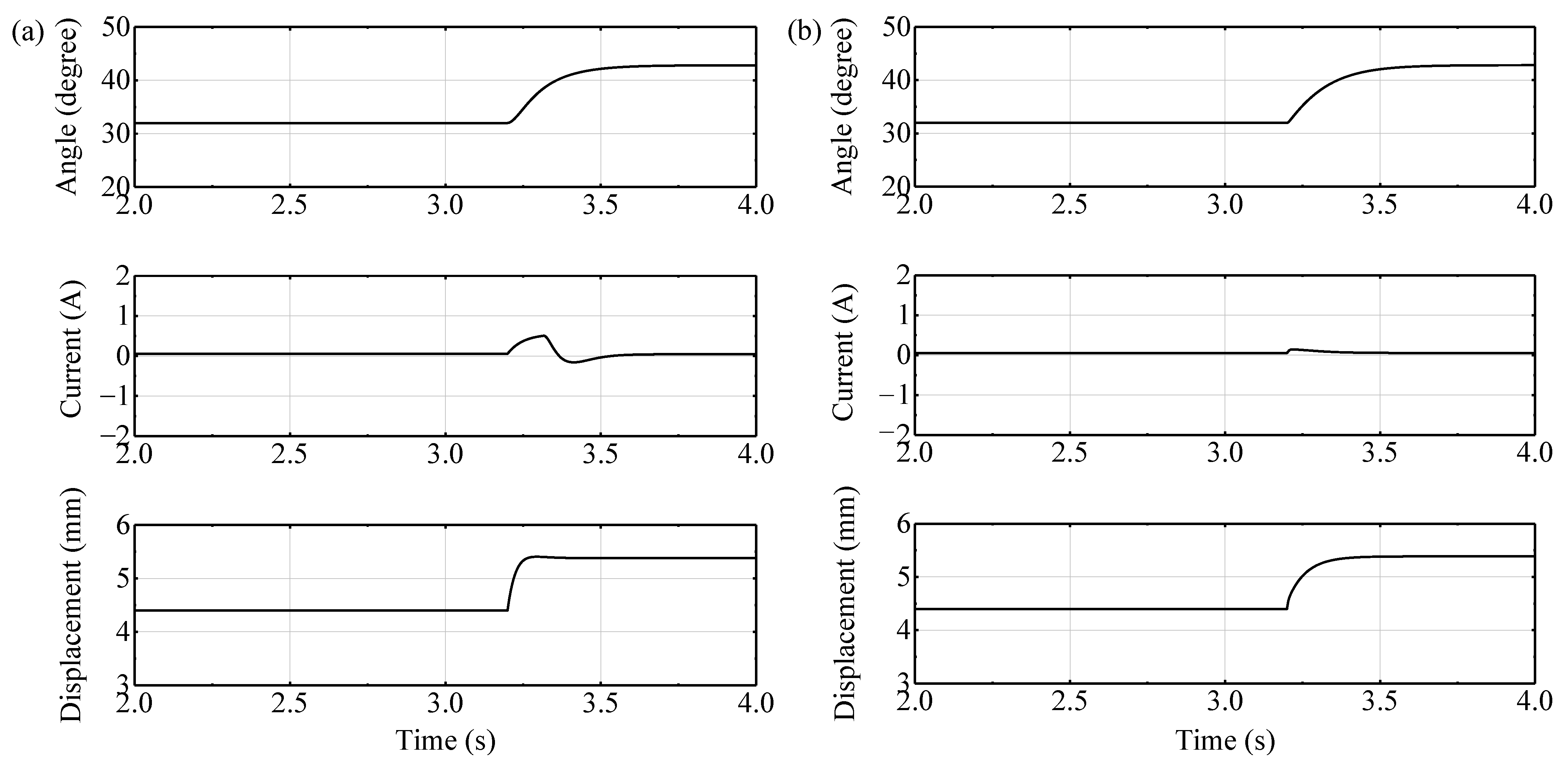
4.1. Simulation Results of the Displacement Disturbance

Figure 5 illustrates the simulation results of the system that added the displacement disturbance at 3.2 s, and the simulation results between 2.0 s and 4.0 s of the PLFCC and the ALFCC are plotted in Figure 5a,b, respectively. Meanwhile, the position of the suspended object, the angle of the PM and the input current of the motor are recorded. It can be seen that the motor current and the magnet angle are increased as the displacement of the suspended object increases, and the position of the suspended object is 4.8 mm in the suspension state by the two fuzzy cascade control methods when the angle of the PM reaches a stable state again. However, the overshoot of the system using the PLFCC is greater compared with the ALFCC. Furthermore, it can be found that the changing current of the PLFCC is greater than that of the ALFCC, and the input current of the motor is less than 0.1 A in the suspension state; hence, zero power performance can be achieved. In addition, the response time of the ALFCC is nearly 0.13 s faster than that of the PLFCC.

4.2. Simulation Results of the Force Disturbance

The simulation results of the system that added the force disturbance at 3.2 s are shown in Figure 6, and the simulation results between 2.0 s and 4.0 s of the PLFCC and the ALFCC are illustrated in Figure 6a,b, respectively. It can be seen that the magnet angle and the motor current are increased with the increase of the suspended object, then the motor current is decreased when the suspended object reaches a new stable state, finally, the magnet angle and the motor current reach a stable state again. The position of the suspended object is 5.3 mm in the suspension state by the two fuzzy cascade control methods when the system is affected by the external force, and it takes 0.19 s faster for the PLFCC to reach the new suspension state than the ALFCC, and the changing current of the PLFCC is greater than that of the ALFCC.

5. Experiment Verification

The purpose of this section is to verify the performance of the proposed permanent magnetic system at the two fuzzy cascade control methods. The prototype is manufactured to simulate the single point permanent magnetic suspension system, and the experiment setup is set up to measure the displacement, rotation angle and input current of the suspension system. As shown in Figure 7, the prototype mainly consists of two PMs, four F-shape cores, a displacement sensor, a servo motor, a bearing and a suspended object. The suspension experiments are carried out to validate the simulation results; furthermore, the comparison experiments between the fuzzy cascade control and cascade control need to be carried out to analyze the effects of the fuzzy cascade control on the suspension performance of the system.

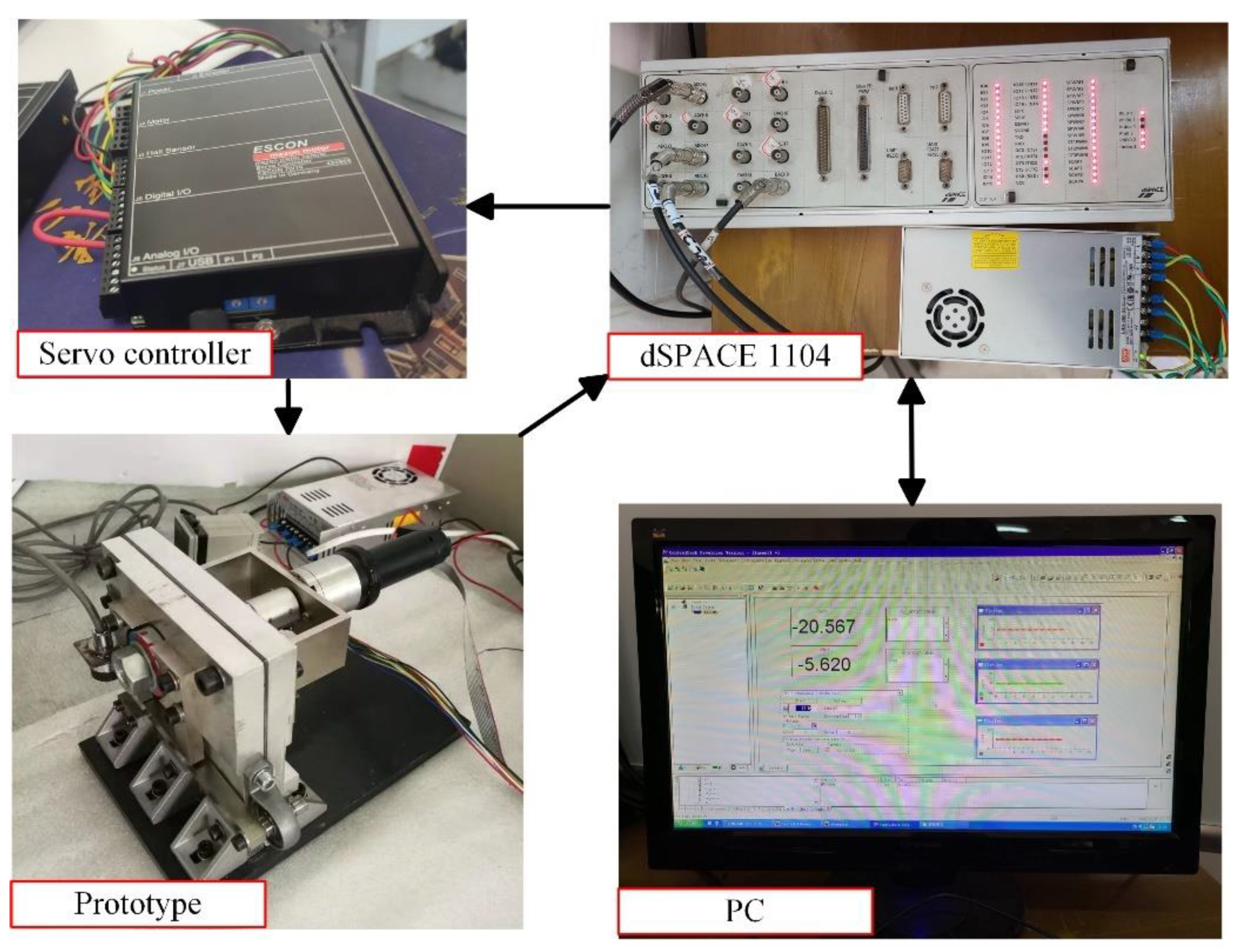
5.1. Experimental Setup

As shown in Figure 8, the experimental setup is established to investigate the effect of the fuzzy cascade control on the suspension system. The suspension system mainly consists of a PC, a dSPACE 1104, a servo controller (ESCON 70/10, Germany) and a prototype, in which the servo controller is used to drive the rotation of the servo motor (EC-max30, Switzerland), and the PMs (NdFeB30) are driven by the servo motor. Moreover, the displacement sensor (EX-V, Keeneshi) is utilized to measure the displacement of the suspended object; the displacement signal of the sensor and the angle signal of the motor are collected by the A/D interface of the dSPACE 1104, and the collection data are stored using the PC. The output signal calculated by the controller is transmitted to the servo controller by the D/A interface of the dSPACE 1104.

5.2. Experimental Results

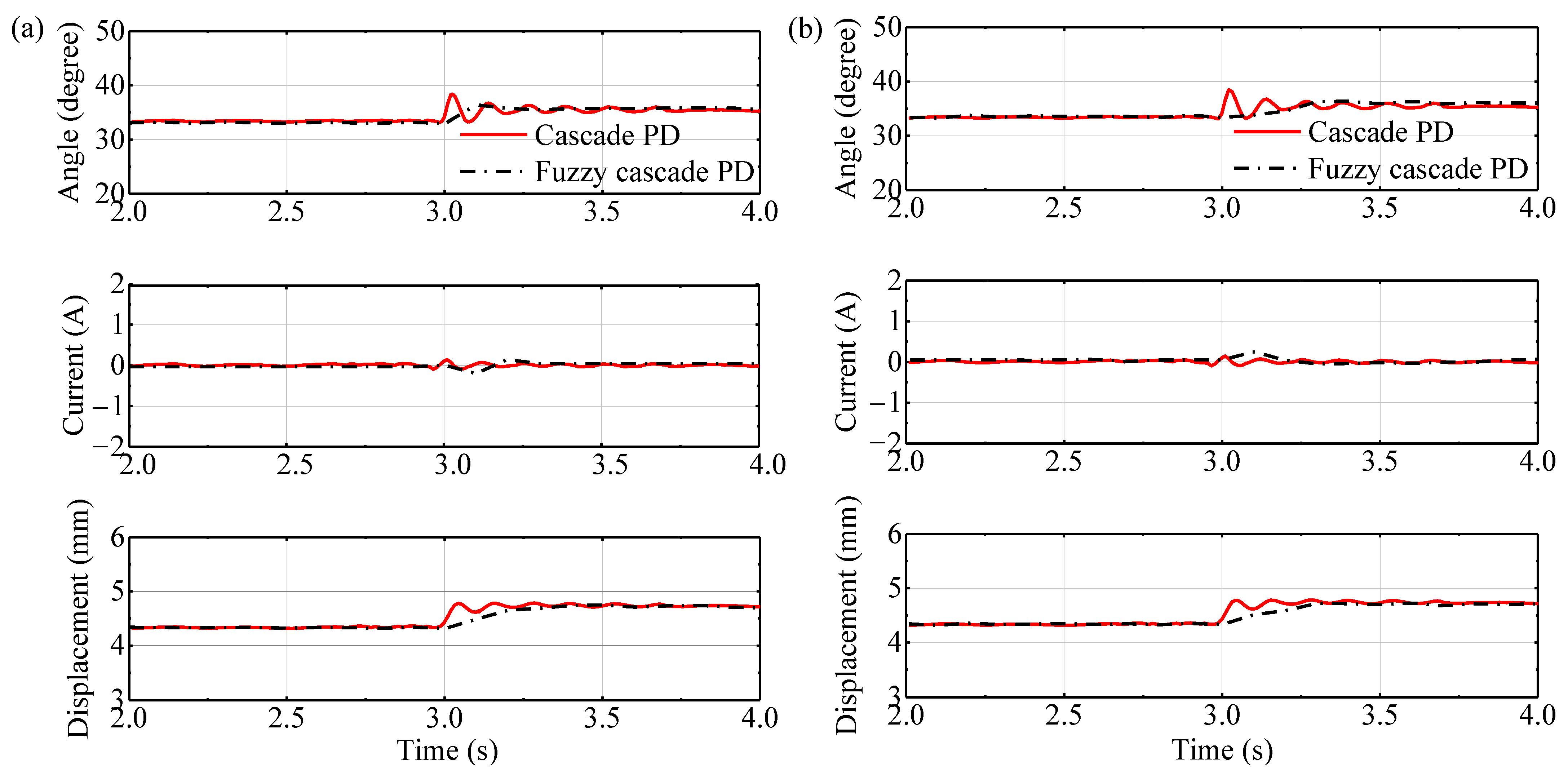
5.2.1. Experimental Results of the Displacement Disturbance

Figure 9 illustrates the compared results of the displacement disturbance experiments at the cascade control and fuzzy cascade control, in which the compared results between 2.0 s and 4.0 s of the PLFCC and the ALFCC are shown in Figure 9a,b, respectively. In the initial stable state of the system, the displacement disturbance signal is imposed on the system at 3.0 s, and the angle of the PM, motor current and position of the suspended object are tracked. It can be found from Figure 9 that the angle of the PM and the suspension force are decreased as the air gap increases when the displacement disturbance is imposed; in order to maintain the stable suspension state of the suspended object, the angle of the PM adjusted by the controller is increased to increase the suspension force. Furthermore, the results demonstrate that the overshoot of the fuzzy cascade control is smaller, and compared with the cascade control, the response times for the PLFCC and the ALFCC to achieve the stable suspension are 0.50 s and 0.40 s faster, respectively. Meanwhile, the motor current is zero in the new stable state, which can meet the characteristics of zero power. In addition, the whole changing trend of the measurement is consistent with the simulation results.

5.2.2. Experimental Results of the Force Disturbance

The compared experimental results of the force disturbance are at the cascade control and the fuzzy cascade control as shown in Figure 10, and the system in the stable state is subjected to the external force disturbance signal at 3.0 s. The compared results between 2.0 s and 4.0 s of the PLFCC and the ALFCC are plotted in Figure 10a,b, respectively. The results demonstrate that the air gap is increased when the suspended object is subjected to the external force, and the motor current calculated by the controller is increased to make the angle of the PM increase, which can provide greater suspension force to keep the suspended object stable. At the same time, compared with the cascade control, the response times for the PLFCC and the ALFCC to achieve the stable suspension are 0.60 s and 0.50 s faster, respectively. Moreover, because the external force disturbance is that of a heavy object being placed in the middle of the suspended solids, the placement speed of the external force can affect the response time of the system when the external force is added. However, the motor current calculated by the two control methods of the system is the same under the new stable state.

5.2.3. Comparison Analysis

Based on the simulated and the experimental results, the comparisons of the response time for the fuzzy cascade controller at the displacement disturbance and the force disturbance are shown in Table 4. It can be found that the simulated results for the response time are less than 0.4 s, and the response time difference between the two control methods is less than 0.2 s. Furthermore, the response times of the experimental results for the two control methods are less than 0.3 s, and it takes 0.10 s faster for the PLFCC to reach the new suspension state than the ALFCC at the external disturbance. In addition, the response time difference of the simulated results is greater than that of the experimental results. According to the above analysis, there is a certain deviation between the simulated results and the experimental results, which is caused by the error of the mathematical model. The mathematical model of the suspension system is linearized at the equilibrium position, and the controller of the system is the PD controller; hence, there is a certain error in the mathematical model when the system reaches the new equilibrium position. In addition, the mechanical system has a certain hysteresis in operation, and the hysteresis phenomenon also occurs when the F-shape cores are magnetized by the permanent magnet. Therefore, there is a certain deviation between the simulated results and experimental results of response time.

5.3. Discussion

The control effects of the designed fuzzy cascade controller on the proposed ZPPMSS-VFPC have been verified in Section 5.2. Compared with the cascade controller, the fuzzy controller is added to the cascade controller, which can modify the parameters of the cascade controller. Hence, the response time and overshoot of the suspension system with the fuzzy cascade controller are improved and decreased, respectively.
Furthermore, the two control methods are presented in this paper, in which the fuzzy controllers of the PLFCC and ALFCC modify the PD parameters of the position loop and angle loop in the cascade controller, respectively. In the PLFCC, the position deviation and the change rate of position deviation are utilized to modify the PD parameters of the position loop, which can obtain the high accuracy angle by the P1D1 controller; then the calculated angle and feedback angle are calculated by the P2D2 controller to obtain the motor current. However, in the ALFCC, the position deviation is calculated by the P1D1 controller to obtain the angle, and the angle deviation and the change rate of the angle deviation are used to modify the PD parameters of the angle loop, then the angle deviation is calculated by the modified P2D2 controller to obtain the motor current. It can be found that the position signal which plays a key role in the suspension system is corrected in advance, which can reduce the response time of the system. Therefore, the control effect of the PLFCC is better than that of the ALPCC.

6. Conclusions

The fuzzy cascade controller for the proposed ZPPMSS-VFPC is designed in this paper. According to the characteristics of the cascade control, the PLFCC and the ALFCC are presented, and the control effects of the two fuzzy cascade controllers on the suspension system at the displacement disturbance and the force disturbance are investigated. The control experiments are carried out to test and verify the control effects of the designed fuzzy cascade for the proposed ZPPMSS-VFPC. The conclusions can be obtained as follows:
(1)
The proposed ZPPMSS-VFPC can realize the stable suspension at the external disturbance by the designed fuzzy cascade controller.
(2)
Compared with the cascade controller, the response times of the designed fuzzy cascade controller at the displacement disturbance and the force disturbance are 0.50 s and 0.60 s faster, respectively, and the suspension system with the fuzzy cascade controller has better robustness and smaller overshoot.
(3)
The response times of the PLFCC at the displacement disturbance and the force disturbance are 0.10 s faster than that of the ALFCC, respectively.
(4)
The response time difference of the experimental results for the two control methods is 0.10 s, which is less than that of the simulated results.
Overall, the designed fuzzy cascade controller has the advantages of simple structure, strong adaptability and self-adjusting parameters for the single point permanent magnetic suspension system, which lays the foundation for suspension performance analysis in the dust-free transportation system with the ZPPMSS-VFPC. In future work, the suspension performances of the dust-free transportation system will be investigated.

Author Contributions

Conceptualization, J.J., S.Y. and F.S.; methodology, H.Z.; validation, R.Z. and Y.G.; formal analysis, H.Z., R.Z. and Y.G.; writing—original draft preparation, H.Z.; writing—review and editing, R.Z., J.J., S.Y. and F.S.; supervision, J.J., S.Y. and F.S.; funding acquisition, J.J. and F.S. All authors have read and agreed to the published version of the manuscript.

Funding

This research was funded by the National Natural Science Fund of China (grant number 52005345, grant number 52005344), National Key Research and Development Project (grant number 2020YFC2006701), Liaoning Revitalization Talents Program (grant number XLYC1802077, grant number XLYC1905003) and Scientific Research Fund Project of Liaoning Provincial Department of Education (grant number LFGD2020002, grant number LJGD2019011).

Acknowledgments

The authors would like to express their thanks to the National Natural Science Fund of China, National Key Research and Development Project, Liaoning Revitalization Talents Program and Scientific Research Fund Project of Liaoning Provincial Department of Education.

Conflicts of Interest

The authors declare no conflict of interest.

Nomenclature

θ The rotation angle of the PM
l 1 The horizontal distance from the bearing to the right F-shape core
l 2 The horizontal distance from the bearing to the left F-shape core
l 3 The horizontal distance from the bearing to the displacement sensor
d f 1 Distance from the suspended object to the bottom of the left F-shape core
d f 2 Distance from the suspended object to the bottom of the right F-shape core
α The angle between the suspended object and the horizontal line
k τ Torque coefficient of the system
k m Suspension force coefficient of the system
Δ d τ Leakage flux compensation coefficients of the torque
Δ d f Leakage flux compensation coefficients of the suspension force
d f 3 Distance from the suspended object to the bottom of the left F-shape core
c 1 Damping coefficients of the PM
c 2 Damping coefficients of the suspended object
J 1 Moments of inertia of the motor
J 2 Moments of inertia of the suspended object
k t Torque coefficient of the servo motor
i The input current of the servo motor
F The external disturbing force acting on the system
l l Length of the suspended object
f m f 1 Suspension forces generated by the left F-shape core
f m f 2 Suspension forces generated by the right F-shape core

References

  1. Chen, S.Y.; Lin, F.J. Robust nonsingular terminal sliding-mode control for nonlinear magnetic bearing system. IEEE Trans. Control Syst. Technol. 2011, 19, 636–643. [Google Scholar] [CrossRef]
  2. Chamroon, C.; Cole, M.O.T.; Fakkaew, W. Linearizing control of a distributed actuation magnetic bearing for thin-walled rotor systems. Actuators 2020, 9, 99. [Google Scholar] [CrossRef]
  3. Sun, Y.; Xu, J.; Qiang, H.; Lin, G. Adaptive Neural-fuzzy robust position control scheme for maglev train systems with experimental verification. IEEE Trans. Ind. Electron. 2019, 66, 8589–8599. [Google Scholar] [CrossRef]
  4. Li, M.; Luo, S.H.; Ma, W.H.; Li, T.; Gao, D.G.; Xu, Z.Q. Experimental and numerical investigations of the dynamic responses of low and medium speed maglev train-track-bridge coupled system. Veh. Syst. Dyn. 2020, 5, 1–24. [Google Scholar] [CrossRef]
  5. Shi, C.; Sun, F.; Dou, R.T.; Ren, H.Z.; Li, Q.; Xu, F.C.; Zhang, X.Y. Modeling and simulation analysis of oil-free scroll compressor driven by magnetic force. Int. J. Appl. Electromagn. Mech. 2020, 64, 1269–1278. [Google Scholar] [CrossRef]
  6. Zhu, J.; Song, D.D.; Han, Q.L.; Li, S.L.; Wang, J.M.; Li, G.H.; Cao, D. Multi objective optimization on suspension characteristics of vertical axis wind turbine. Int. J. Appl. Electromagn. Mech. 2018, 58, 215–226. [Google Scholar] [CrossRef]
  7. Yu, Y.J.; Zhang, W.Y.; Sun, Y.X.; Xu, P.F. Basic Characteristics and Design of a Novel Hybrid Magnetic Bearing for Wind Turbines. Energies 2016, 9, 905. [Google Scholar] [CrossRef] [Green Version]
  8. Kim, J.Y.; Ahn, D. Analysis of high force voice coil motor for magnetic levitation. Actuators 2020, 9, 133. [Google Scholar] [CrossRef]
  9. Zhou, R.; Sun, F.; Yan, M.Y.; Jin, J.J.; Li, Q.; Xu, F.C.; Zhang, X.Y.; Nakano, K. Design, analysis and prototyping of a magnetic energy-harvesting suspension for vehicles. Smart Mater. Struct. 2020, 29, 105034. [Google Scholar] [CrossRef]
  10. Gu, C.; Wang, X.L.; Deng, Z.Q. Evaluation of three improved space-vector-modulation strategies for the high-speed permanent magnet motor fed by a SiC/Si hybrid inverter. IEEE Trans. Power Electron. 2021, 36, 4399–4409. [Google Scholar] [CrossRef]
  11. Kawase, Y.; Ota, T.; Fukunaga, H. 3-D eddy current analysis in permanent magnet of interior permanent magnet motors. IEEE Trans. Magn. 2002, 36, 1863–1866. [Google Scholar] [CrossRef]
  12. Park, S.Y.; Lee, D.Y.; Song, B.C.; Baek, Y.S. Analysis and modeling of attractive force using an electropermanent magnet and electromagnetic in a novel wobble gripper. Actuators 2020, 9, 116. [Google Scholar] [CrossRef]
  13. Wang, Z.; Long, Z.; Li, X. Levitation control of permanent magnet electromagnetic hybrid suspension maglev train. Proc. Inst. Mech. Eng. Part I J. Syst Control Eng. 2018, 232, 315–323. [Google Scholar] [CrossRef]
  14. Park, S.U.; Mok, H.S.; Lim, J.W.; Seo, H.U.; Oh, S.H. Efficiency improvement by deriving the optimal operating slip frequency of a linear-induction-style maglev train. Energies 2020, 13, 6544. [Google Scholar] [CrossRef]
  15. Chaban, A.; Lukasik, Z.; Lis, M.; Szafraniec, A. Mathematical modeling of transient processes in magnetic suspension of maglev trains. Energies 2020, 13, 6642. [Google Scholar] [CrossRef]
  16. Han, J.W.; Kim, J.D.; Song, S.Y. Fatigue strength evaluation of a bogie frame for urban maglev train with fatigue test on full-scale test rig. Eng. Fail. Anal. 2013, 31, 412–420. [Google Scholar] [CrossRef]
  17. Zhou, D.F.; Yu, P.C.; Wang, L.C.; Li, J. An adaptive vibration control method to suppress the vibration of the maglev train caused by track irregularities. J. Sound Vibr. 2017, 408, 331–350. [Google Scholar] [CrossRef]
  18. Spece, H.; Fittro, R.; Knospe, C. Optimization of axial magnetic bearing actuators for dynamic performance. Actuators 2018, 7, 66. [Google Scholar] [CrossRef] [Green Version]
  19. Bonfitto, A.; Castellanos Molina, L.M.; Tonoli, A.; Amati, N. Offset-free model predictive control for active magnetic bearing systems. Actuators 2018, 7, 46. [Google Scholar] [CrossRef] [Green Version]
  20. Schuhmann, T.; Hofmann, W.; Werner, R. Improving operational performance of active magnetic bearings using kalman filter and state feedback control. IEEE Trans. Ind. Electron. 2011, 59, 821–829. [Google Scholar] [CrossRef]
  21. Sun, F.; Oka, K. Development of noncontact suspension mechanism using flux path control by disk magnet rotation. Trans. Jpn. Soc. Mech. Eng. 2010, 76, 2916–2922. [Google Scholar] [CrossRef] [Green Version]
  22. Sun, F.; Oka, K.; Saibara, Y. Magnetic suspension system by flux path control using rotary actuator. Int. J. Appl. Electromagn. Mech. 2010, 33, 769–776. [Google Scholar] [CrossRef]
  23. Sun, F.; Zhou, R.; Jin, J.; Li, Q.; Oka, K. Optimal design for quasi-zero power performance of a permanent magnetic suspension system. Int. J. Appl. Electromagn. Mech. 2018, 59, 607–616. [Google Scholar] [CrossRef]
  24. Xu, F.C.; Guo, Y.Q.; Zhou, R.; Jin, J.J.; Zhao, C.; Zhang, X.Y.; Sun, F. Analysis of structure factors affecting suspension force of permanent magnet system with variable magnetic flux path control. Int. J. Appl. Electromagn. Mech. 2020, 64, 1495–1504. [Google Scholar] [CrossRef]
  25. Mercado-Uribe, A.; Moreno, J.A. Homogeneous integral controllers for a magnetic suspension system. Control Eng. Pract. 2020, 97, 104325. [Google Scholar] [CrossRef]
  26. Pesch, A.H.; Sawicki, J.T. Active magnetic bearing online levitation recovery through μ-synthesis robust control. Actuators 2017, 6, 2. [Google Scholar] [CrossRef] [Green Version]
  27. Wei, C.S.; Soffker, D. Optimization strategy for PID-controller design of AMB rotor systems. IEEE Trans. Control Syst. Technol. 2016, 24, 788–803. [Google Scholar] [CrossRef]
  28. Wei, W.; Xue, W.C.; Li, D.H. On disturbance rejection in magnetic levitation. Control Eng. Pract. 2019, 82, 24–35. [Google Scholar] [CrossRef]
  29. Anantachaisilp, P.; Lin, Z.L. Fractional order PID control of rotor suspension by active magnetic bearings. Actuators 2017, 6, 4. [Google Scholar] [CrossRef] [Green Version]
  30. Zhou, R.; Yan, M.Y.; Guo, Y.Q.; Jin, J.J.; Sun, F.; Zhang, X.Y.; Oka, K. Suspension characteristics of a zero-power permanent magnetic suspension system with flux path control. Int. J. Appl. Electromagn. Mech. 2020, 63, 187–198. [Google Scholar] [CrossRef]
  31. Sun, X.W.; Lu, Y.Y.; Sun, F.; Jin, J.J.; Wang, K. Research on dynamics performance of permanent magnet suspension system with variable magnetic circuitJ. China Mech. Eng. 2014, 25, 2782–2787. [Google Scholar] [CrossRef]
Figure 1. (a) Three-dimensional model of the proposed ZPPMSS-VFPC; (b) the structure of the suspension device.
Actuators 10 00118 g001aActuators 10 00118 g001b
Figure 2. The initial state of the system (left) and the angle θ° of the magnet (right).
Actuators 10 00118 g002
Figure 3. Model diagram of the permanent magnetic suspension system.
Actuators 10 00118 g003
Figure 4. (a) The position loop fuzzy cascade control; (b) the angle loop fuzzy cascade control.
Actuators 10 00118 g004
Figure 5. Simulation results of the displacement disturbance: (a) position loop fuzzy cascade control; (b) angle loop fuzzy cascade control.
Actuators 10 00118 g005
Figure 6. Simulation results of the force disturbance: (a) position loop fuzzy cascade control; (b) angle loop fuzzy cascade control.
Actuators 10 00118 g006
Figure 7. The experimental prototype: (a) the front of the prototype; (b) the back of the prototype.
Actuators 10 00118 g007
Figure 8. The experimental setup.
Actuators 10 00118 g008
Figure 9. Experimental results of the displacement disturbance: (a) position loop fuzzy cascade control; (b) angle loop fuzzy cascade control.
Actuators 10 00118 g009
Figure 10. Experimental results of the force disturbance: (a) position loop fuzzy cascade control; (b) angle loop fuzzy cascade control.
Actuators 10 00118 g010
Table 1. The fuzzy control rules table of Δkp.
ecNBNMNSZOPSPMPB
e
NBNBNBNMNMNSZOZO
NMNBNBNMNSNSZOPS
NSNMNMNMNSZOPSPS
ZONMNMNSZOPSPMPM
PSNSNSZOPSPMPMPM
PMNSZOPSPMPMPBPB
PBZOZOPMPMPMPBPB
Table 2. The fuzzy control rules table of Δkd.
ecNBNMNSZOPSPMPB
e
NBNBNSNSNMNMNMNB
NMNBNSNSNSNSNSNB
NSNSZOZOZOPSPSZO
ZOZOPSPSPSPMPMZO
PSZOPSPSPMPMPSPS
PMZOPSPMPMPBPSNS
PBNSPMPBPBPBPSNS
Table 3. Structure parameters of the system.
ParametersDescriptionValue
mQuality of the suspended object0.142 kg
ΔdτMagnetic leakage compensation constant of the torque21 mm
ΔdfMagnetic leakage compensation constant of the suspension force2 mm
c1Damping coefficient of the PM0.5 N·m·s−1
c2Damping coefficient of the suspended object10 N·m·s−1
J1Moment of inertia of the PM1.856 × 10−5 kg·m2
J2Moment of inertia of the suspended object1.108 × 10−3 kg·m2
ktTorque constant of the servo motor0.69 Nm/A
kτTorque constant of the PM8.726 × 10−3 Nm2
kmConstant of the suspension force6.277 × 10−5 Nm2
Table 4. Comparison results of the response time.
DescriptionSimulated Response TimeExperimental Response Time
PLFCC for the displacement disturbance0.26 s0.20 s
ALFCC for the displacement disturbance0.13 s0.30 s
PLFCC for the force disturbance0.19 s0.20 s
ALFCC for the force disturbance0.38 s0.30 s
Publisher’s Note: MDPI stays neutral with regard to jurisdictional claims in published maps and institutional affiliations.

