1. Introduction
With the widespread use of robots in many areas of modern industry, there is an increasing demand for stability and accuracy in robot grasping. Flexible manipulation in a complex environment relies heavily on visual feedback, with which the robot can recognize the object and then control the manipulator to complete the grasp. The basis of the visual system is the hand–eye calibration that the relationship between the robot’s world coordinate system and the camera coordinate system can obtain [
1]. The base coordinates of the object in space can be calculated from the pixel information in the camera with the aid of an obtained coordinate transformation relationship [
2]. Therefore, the accuracy of robot manipulation and the stability of the visual system are determined by the hand–eye calibration algorithm.
1.1. Related Work
The problem of robotic hand–eye calibration was posed as
, which was first investigated by Shiu et al., who gave the basic solution method of the
equation [
3]. Relevant parameters can be obtained by using the projection geometric transformation of known points of the calibration objects. Subsequently, Tsai et al. introduced a method to calculate the pose of the camera relative to the end of the manipulator during hand–eye calibration, which is simple, efficient, and accurate [
4]. However, the algorithm only considers radial distortion, so the effect is not good when the lens tangential distortion is serious. Zhang et al. proposed the single-plane chessboard calibration method, which does not require the use of high-precision 3D calibration objects; it has been widely applied [
5,
6]. Zhuang et al. put forward a method to transform matrix equation
into
and used quaternions for a solution, which is suitable for precise positioning of the robot [
7]. For the hand–eye calibration of the robot arm, spinor theory, optimization theory, and other methods have been proposed to solve the transformation matrix [
8].
However, the above calibration techniques are based on precise mathematical models, so the uncertainty of internal and external parameters will cause the estimation error of the system [
9]. Moreover, optical characteristics of the camera in different scenes are changeable, so the accurate model will inevitably lead to a strong correlation between parameters [
10]. It is difficult for algorithms to achieve theoretical results with the increase in frequent manipulation because the mechanical part will be worn and parameters of each part will change [
11]. Commonly, the relationship between the robot base and the camera can be approximated by traditional calibration methods [
12]. However, these algorithms typically cause a certain level of inaccuracy in the calibration process.
1.2. Proposed Method and Contributions
In order to overcome the above disadvantages, a new method based on neural network that can determine the nonlinear mapping relationship was proposed in this study [
13]. The ability of feature extraction and function fitting not only avoids limitation but also has better flexibility than traditional algorithms [
14]. The accurate calibration model can be learned by optimizing parameters, which is helpful to build a system with faster convergence speed and higher precision [
15]. In addition, some uncertainties are averted, such as the replacement of various sensors in different conditions, which reduces the calibration workload and inaccuracy [
16]. Therefore, in order to achieve accurate robot manipulation, it is necessary to spend research efforts into calibration of the hand–eye coordinate relationship [
17].
As an alternative approach, the calibration method based on a neural network simplifies the process and improves the precision of the calibration. Thus, for the calibration
problem, this study proposed an efficient approach based on a neural network. Experiments were carried out to demonstrate the efficiency and robustness of the proposed method. The main contributions offered by this work was to formulate the hand–eye coordinate calibration as
, based on neural network optimization, from which the calibration result was ultimately acquired. The comparative study involving existing methods also revealed that the proposed method offers higher grasping accuracy when considering various noise [
18].
The remainder of the study is arranged as follows. In
Section 2, we introduce the principle of hand–eye calibration and the traditional solutions as well as the advantages of a neural network.
Section 3 focuses on the construction of a neural network that can help establish the relationship between the pixel coordinates and the base coordinates of the robot arm. In
Section 4, the performance of the traditional method and the proposed method are compared via the experiment, and the optimization method of the neural network is discussed according to the experimental result. Finally, the conclusion that the new method has higher precision and generalizability is given and future research is described.
2. Problem Statement
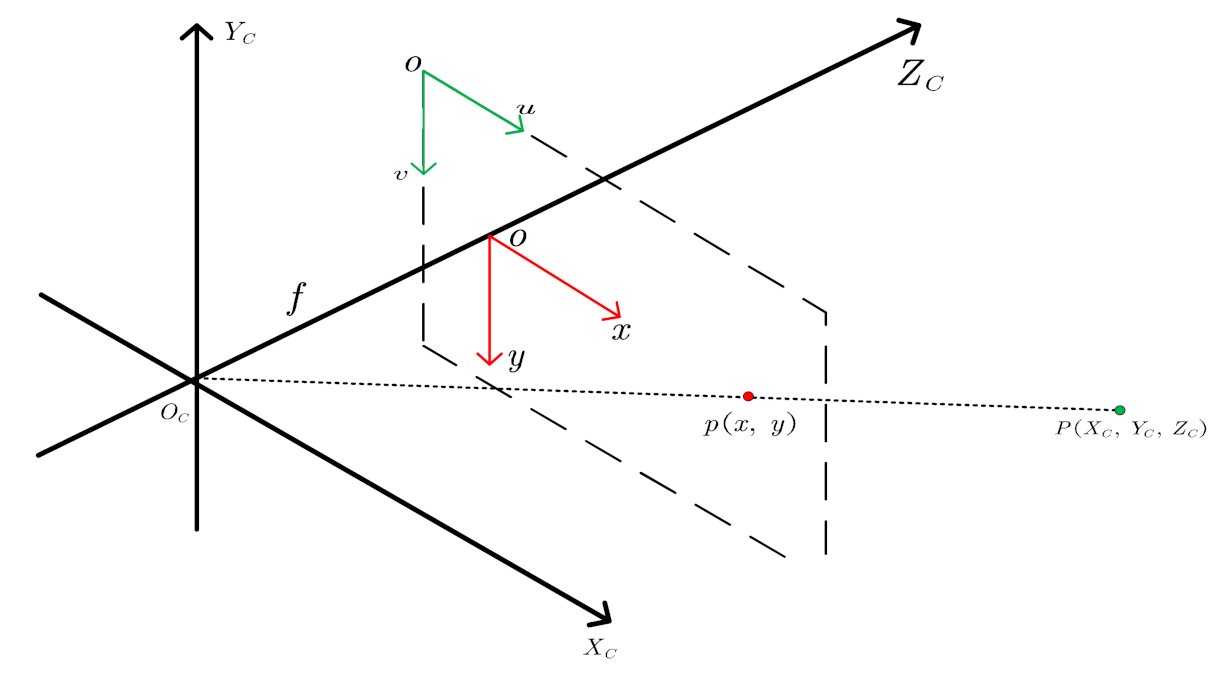
The visual servo system of the robot can help the robot to realize the target positioning and grasping, but we only receive the image coordinate of the target from the picture. The method of hand–eye calibration was proposed to solve this problem. This method can help establish the transformation relationship between the camera coordinate system and the robot coordinate system. The basis of hand–eye calibration is related to the imaging principle of the camera, and the physical model is generally established by pin-hole imaging. For the convenience of understanding, the pin-hole imaging model was transformed into an imaging model in a camera coordinate system that is shown in
Figure 1.
As shown in
Figure 1, the coordinate of point
in the camera coordinate system is
, and the projection in the image coordinate system is the point
. Then, the relationship between the base coordinate system and the camera coordinate system should be constructed based on the equation:
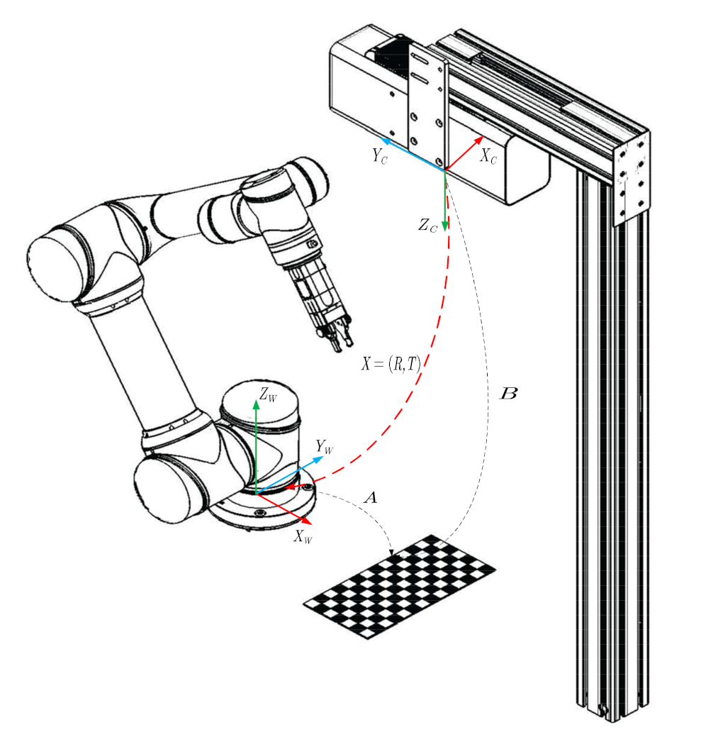
. The hand–eye calibration principle of the grasping platform is shown in
Figure 2.
As shown in
Figure 2, the pose of the corner point in the base coordinate of the manipulator was defined as A, the pose of the corner point in the camera coordinate was B, and the conversion relation between the camera coordinate and the base coordinate was set as X. The actual lens cannot be considered as a small hole but an optical system composed of several lenses with a certain area and thickness. Therefore, there must be various errors in the system, which lead to certain distortions in the imaging process. In order to ensure the precision of the calibration results, it was necessary to construct the imaging model according to geometric characteristics of the imaging model, internal parameters, external parameters, and distortion parameters. The relationship between the pixel coordinate system and the world coordinate system is summarized as Formula (1).
In this way, the essential problem of the hand–eye calibration is how parameter values of the transformation matrix can be acquired according to the corner pixel coordinates: and world coordinates: . However, the precise calibration of the hand–eye relationship is complex and traditional algorithms have some limitations that cannot manifest the nonlinear mapping relationship accurately.
In light of the reasons just mentioned, many researchers have begun to explore a more adaptive and robust method of hand–eye calibration. Horaud et al. discussed the possibility and the feasibility that the sensing information from the image space was mapped to the robot control space directly [
19]. Lee realized the positioning of the robot by adopting the method of neural networks [
20]. Huang realized the grasping of various objects in three-dimensional space via multiple cameras without calibration. Above discussion clearly shows that not every parameter in the hand–eye calibration needs to be calculated, so it is feasible to establish a direct mapping from vision to manipulator control.
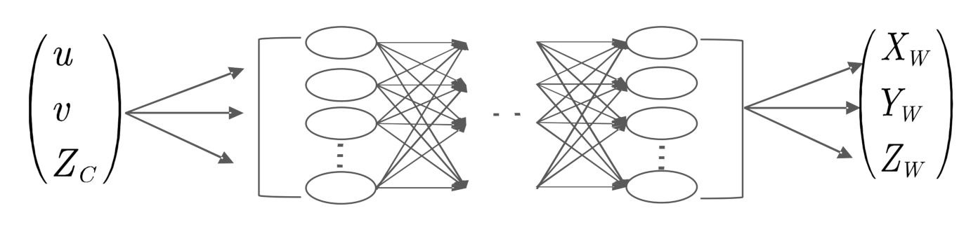
Both neural network and hand–eye calibration derive unknown parameter models from known data; moreover, the neural network has a strong nonlinear approximation ability. The appropriate neural network structure can fit the relationship between the robot and the camera so well that the mathematical model is difficult to describe. The idea of this study was that the thimble of the robot arm aims at each corner on the calibration plate, so the coordinate of the corner in the image and the position of the thimble in the base can be identified simultaneously. Coordinates of corners are the input, and coordinates of the thimble are the output. These data are trained on a neural network, which can fit the nonlinear mapping between manipulator and camera. The training model based on the neural network is shown in
Figure 3.
The hand–eye calibration method based on the neural network does not need manual intervention; this can effectively overcome various errors during the manipulation and can ensure accuracy and stability. Therefore, the robot vision system can receive the best calibration model based on the proposed method. Next, it was necessary to select an appropriate network structure and optimize it to better fit the coordinate transformation model. The learning process of the optimal calibration model can be interpreted as by optimizing the network structure and parameters.
3. Neural Network Optimization
From the above analysis, it can be seen that the mapping model between object base coordinates and image coordinates contained internal parameters, external parameters, and distortion parameters. These parameters needed to be obtained through complex experiments and calculations, and the early calibration methods needed to establish the transformation relationship between coordinates by using highly accurate calibration objects. At present, the most widely used calibration method is the Zhang Zhengyou calibration method, which does not require three-dimensional calibration objects but uses the principle of perspective invariance of the topological structure of the calibration plate to ensure the correspondence between object points and image points. This calibration method only needs to get checkerboard pictures from multiple angles to establish the relationship between the pixel coordinate system and the object coordinate system.
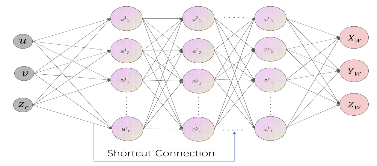
It is clear from the above research that each parameter does not need to be calculated, and it is feasible to establish a direct mapping from vision to robot control based on a neural network. Then, it was necessary to design an appropriate algorithm for the proposed hand–eye calibration model and optimize its structure and parameters to obtain the optimal coordinate transformation model. In combination with the demand of hand–eye calibration and the characteristics of the current neural network structure, this study proposed to integrate the quick structural connection module of the Resnet network on the basis of the artificial neural network algorithm, so as to better solve the problems of gradient disappearance and overfitting and realize the continuous improvement of the network performance with the deepening of the layer. The diagram of the network structure is shown in
Figure 4.
Compared with the traditional hand–eye calibration method, this method reduces the search space, can obtain more accurate results, and can learn from the environment to improve the robot’s understanding and adaptability to the environment. The optimization of the artificial neural network mainly includes accuracy, convergence speed, and generalization ability, and the updating of each parameter is realized by data-driven, so as to fit various complex, nonlinear relations. An appropriate loss function was also needed to build an accurate model. Common loss functions include the mean square error (MSE) and the cross entropy error (cross entropy). The mean square error is the sum of squares of the difference between the predicted value and the true value, but the calculation of squares can easily lead to gradient explosion, which makes it impossible to update the parameter weights from the training data. While entropy in information theory refers to the amount of information in the data, cross-entropy refers to the difference between the predicted value and the true value when entropy is used as the measurement standard. However, the cross-entropy loss function is mainly used for classification. Considering the problems of gradient explosion and gradient disappearance of weight update, it was finally selected as the loss function. The function expression is shown as Formula (2).
By minimizing the loss function, the predicted value of the model can be converging as far as possible. Meanwhile, in order to improve the learning efficiency of the neural network, the initial value of He can be selected as the initial weight parameter to ensure the uniform distribution of activation values at each layer. In addition, the method of batch normalization was also used to optimize the gradient, and the mathematical formula of batch normalization is shown as Formula (3).
can be acquired by normalizing when the mean
and variance
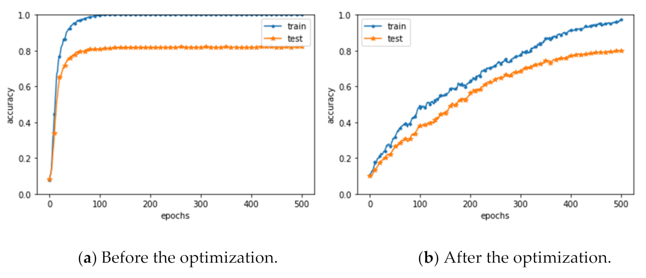
of the input data are obtained. By inserting regularization processing before the activation function, the deviation of data distribution can be effectively reduced, and the accuracy of the model can be further improved. However, regularization also brings a large number of parameters, which will inevitably lead to the phenomenon of overfitting. Therefore, the dropout method was selected to further optimize the network to improve its generalization ability. The comparison of accuracy before and after optimization for overfitting is shown in
Figure 5.
As shown in
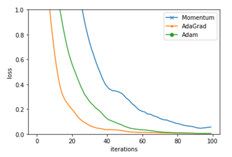
Figure 5, the identification accuracy gap between training data and test data was narrowed through dropout. The ultimate purpose of the neural network is to find the parameter weight to minimize the value of the loss function, and the common methods to find the optimal parameters mainly include the stochastic gradient descent (SGD), the momentum (momentum), and the AdaGrad methods. In order to find an appropriate parameter update method, the optimal solution was found by comparing the differences of the three methods in the learning iteration speed. Differences between the three optimization methods in the learning process are shown in
Figure 6.
It can be seen from
Figure 6 that the learning process based on the AdaGrad parameter update method was the fastest, and, as the number of iterations increased, both the Adam and AdaGrad methods could effectively optimize the neural network. It should be noted that the results will vary with different hyperparameters such as the learning rate, so it is also important to choose the appropriate hyperparameters. In this study, the AdaGrad method with the fastest updating speed was selected naturally. It can properly adjust the learning scale of each parameter by multiplying
, so as to realize the efficient search of parameter space and offset the correction of the super-parameter. Its mathematical expression is shown as Formula (4).
So far, the optimization of the neural network has been basically completed. Through the improvement of the convergence speed and adaptability, the neural network has a good nonlinear function-fitting function and has high accuracy and real-time performance. In comparison, the traditional hand–eye calibration method only considers all factors in the imaging process and does not cover all nonlinear factors. The powerful nonlinear fitting ability of the artificial neural network can solve problems that are difficult to be described by mathematical models, and it is closer to the real model than traditional algorithms. The hand–eye calibration method based on the artificial neural network is an effective method to establish the relationship between image coordinates and robot base coordinates. This algorithm not only simplifies the process of hand–eye calibration but also improves the generality of the algorithm.
4. Experiments and Discussion
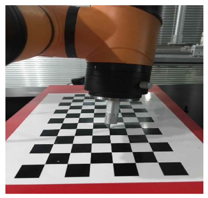
In this section, the effectiveness of the proposed hand–eye calibration model based on neural network is verified via experiments. First of all, we fixed a Comtraix camera directly above the grabbing plane, changed the position of the checkerboard in space, and collected the pictures of the checkerboard. In order to get as large a data range as possible in a picture, the size of the calibration plate was 7 × 14, and the size of each square was 20 mm × 20 mm. The style of the calibration plate is shown in
Figure 7. At the same time, the two-finger gripper at the end of the AUBO robot was replaced by a thimble, and the base coordinate of corresponding thimble point could also be obtained from the manipulator.
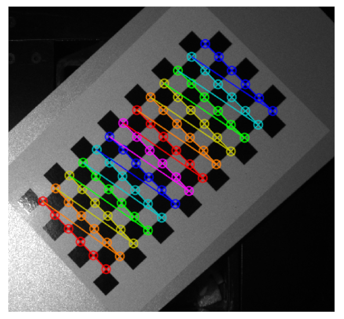
It can be seen from
Figure 8 that the pixel coordinate of every corner can be extracted at each configuration based on the algorithm of the OpenCV software library. Therefore, a set of related coordinates could be obtained from one corner point.
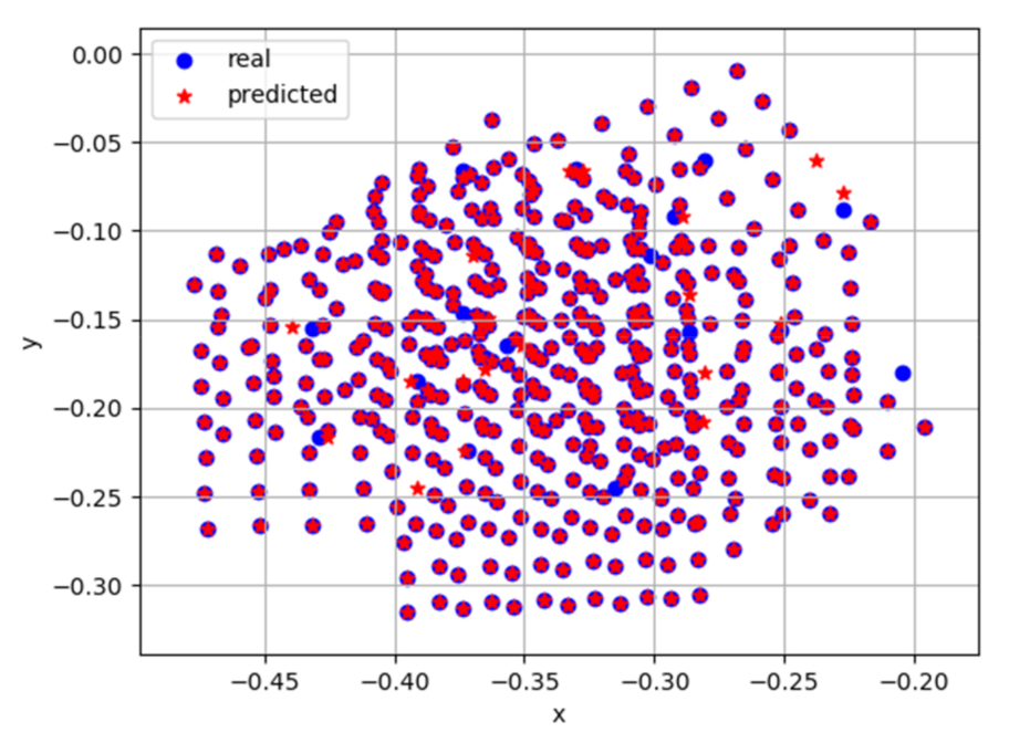
The datasets of pixel coordinates and base coordinates of each corner of checkerboard could be obtained from the above two figures. A total of 20 pictures of the checkerboard calibration board were collected, and each picture could obtain 78 sets of pixel coordinates and the corresponding base coordinates of each corner point. In the training process, it is not necessary to extract all corner coordinates of each image, so the method of picking points at an interval of two points was selected, and a total of 520 points were selected. Then, 400 points were taken as the training set and 120 points as the test set. After dividing the dataset, we could use the dataset to train the proposed network model and verify the test set. The training dataset was input into the proposed artificial neural network, which integrates the shortcut connection module for training, and then the test set was tested. The comparison between predicted results of the neural network and real values is shown in
Figure 9.
As can be seen from
Figure 9, there were still some inaccurate predicted values, but the number was small, possibly because of the interference of noise in the training data; additionally, the error was within the acceptable range of 5%. Experimental results showed that the method proposed in this paper has good accuracy, and, compared with the traditional nine-point hand–eye calibration method, the accuracy was significantly higher than that of the traditional method. The comparison table is shown in
Table 1.
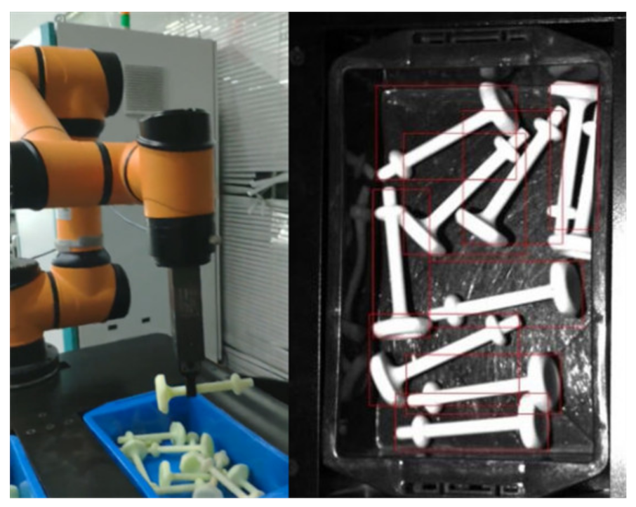
Compared with the traditional algorithm, the hand–eye calibration method based on the neural network had a higher accuracy, simplified the process of hand–eye calibration, and improved the generalization ability of the algorithm. Although the calculation speed of the traditional algorithm was slightly faster, the hand–eye calibration does not need to be run frequently, so it has almost no impact on the real-time performance of the system. Finally, the hand–eye calibration results were used in the robot grasping system, and the stability and accuracy of the hand–eye relationship were verified through grasping experiments, as shown in
Figure 10.
The actual grasping experiment results showed that the gripper could accurately grasp the screw in the frame; even if there was an occasional deviation the screw was still in the operating space of the gripper and grasping could be successfully completed. After statistical analysis of experimental data, the calibration error based on this method could be controlled within 0.02 mm, which is comparable to the positioning accuracy of the robot. Compared with the traditional algorithm, the complicated calibration process is eliminated, and the calibration accuracy is improved. It was proved that the hand–eye calibration neural-network-based algorithm proposed in this study can establish the relationship between the image coordinates and the robot base coordinates.
5. Conclusions
Robot hand–eye calibration based on neural network optimization is viable and can learn the parameter model of coordinate transformation from known data. The neural network has good performance of nonlinear fitting, so it can learn and adapt to dynamic characteristics of various uncertain conditions. An excellent hand–eye calibration model can be obtained by optimizing the structure and parameters. Compared with the traditional algorithm, the calibration method based on a neural network simplifies the process and improves the precision of the calibration. The effectiveness of the proposed method was validated by the experiment, which gives a new direction for hand–eye calibration. The main contributions of this study may be summarized as follows:
(1) Formulating the hand–eye coordinate calibration as based on neural network optimization, from which the calibration result was ultimately acquired.
(2) The efficiency of the neural network optimization algorithm was validated via the experimental results.
(3) The experimental analysis also revealed that the proposed method offered higher grasping accuracy when considering various noise.
In addition, the proposed calibration method mainly focused on the problem of a two-dimensional surface pertaining to a single manipulator with a camera. In the future, the focus will be on the calibration of three-dimensional space with two or more robots. The precision improvement of calibrated results using neural network optimization needs to be studied in more detail.


