Article

Development of a Control System and Functional Validation of a Parallel Robot for Lower Limb Rehabilitation

1
Research Center for Industrial Robots Simulation and Testing (CESTER), Technical University of Cluj-Napoca, 400641 Cluj-Napoca, Romania
2
National Institute for Research and Development of Isotopic and Molecular Technologies, 400293 Cluj-Napoca, Romania
3
Department of Mechanical, Energy and Management Engineering (DIMEG), University of Calabria, 87036 Cosenza, Italy
*
Authors to whom correspondence should be addressed.
Actuators 2021, 10(10), 277; https://doi.org/10.3390/act10100277
Submission received: 20 September 2021 / Revised: 12 October 2021 / Accepted: 13 October 2021 / Published: 18 October 2021
(This article belongs to the Special Issue Advanced Robots: Design, Control and Application)

Abstract

:
This paper is focused on the development of a control system, implemented on a parallel robot designed for the lower limb rehabilitation of bedridden stroke survivors. The paper presents the RECOVER robotic system kinematics, further implemented into the control system, which is described in terms of architecture and functionality. Through a battery of experimental tests, achieved in laboratory conditions using eight healthy subjects, the feasibility and functionality of the proposed robotic system have been validated, and the overall performance of the control system has been studied. The range of motion of each targeted joint has been recorded using a commercially available external sensor system. The kinematic parameters, namely the patient’s joints velocities and accelerations have been recorded and compared to the ones obtained using the virtual model, yielding a very small difference between them, which provides a validation of the RECOVER initial design, both in terms of mechanical construction and control system.

1. Introduction

Stroke is one of the most frequent neurological diseases of our time [1]. In 2013, stroke was the second leading cause of death, accounting for 11.8% of all fatalities globally [2], trailing only ischemic heart disease, which accounted for 14.85% of all deaths. In the European Union in 2017, there were 1.12 million incidents of strokes, 9.53 million stroke survivors, 0.46 million deaths, and 7.06 million disability-adjusted life years lost due to stroke. It is estimated there will be an extra 40,000 incidents of strokes (+3%) and 2.58 million prevalent cases (+27%) by 2047. Lithuania is anticipated to see the biggest increases in age-adjusted incidence and prevalence rates (0.48 percent and 0.7 percent yearly percentage changes, respectively), while Portugal is expected to see the largest decreases (−1.57 percent and −1.3 percent, respectively) [3]. According to the prediction, 4% of adults will have a stroke in 2030, and the yearly medical cost of stroke would rise from 71.55 billion USD in 2012 to 183.13 billion USD in 2030, merely in the United States [4].
The weakening or paralysis of one or more limbs is one of the most prevalent side symptoms of a stroke. Repetitive motions of the impaired limb are frequently used in post-stroke lower limb rehabilitation in order to restore the capacity to conduct everyday tasks with the impaired limb. The repeated therapy actions are carried out according to a predetermined rehabilitation program prepared by medical professionals depending on the individual conditions of the patient. One-third of stroke survivors do not regain independent walking capacity, and those who do often walk in an asymmetric pattern [5]. As rehabilitation therapies are so important for recovery, there is a lot of research undertaken in this area. Conventional rehabilitation methods, particularly gait therapy, are highly labor demanding, needing more than three therapists to manually help the patient’s legs and torso in performing training [6].
In recent years, robotic technology has advanced dramatically, with faster and more powerful processors, new computational techniques, and more sophisticated electro-mechanical components [7]. Due to technological advances, robotic systems are now available for rehabilitative intervention. Rehabilitation robots can help therapists by reducing their workload, detecting data during training, and assisting in the quantitative evaluation of rehabilitation in a controlled and reproducible manner [8].
Several lower-limb rehabilitation robots have been developed in the recent years to regain motion of impaired limbs. An important category of robotic system for lower-limb rehabilitation is treadmill gait trainers, where the therapists supervise the patient walking on a treadmill, with an overhead harness supporting some of the patient’s body weight. Many robotic systems have been developed with the goal of automating and improving this training approach in order to reduce physiotherapist work [9,10,11]. Lokomat (Hocoma AG) [12] is an example of a commercial product in this category that combines a treadmill with a robotic gait orthosis and a sophisticated body weight support system. Another commercial product based of treadmill training is The LokoHelp (LokoHelp Group) [13]. The LokoHelp is positioned in the center of the treadmill surface, parallel to the walking direction, and is secured to the front of the treadmill using a quick clamp. It also offers the patient with a body weight support mechanism. Clinical experiments have been carried out to assess its feasibility and efficacy. The results demonstrate that the system improves the patient’s mobility in the same way as manual locomotion training does; however, utilizing the LokoHelp requires less therapy intervention and reduces therapist discomfort [14]. The Active Leg Exoskeletal (ALEX) is a leg orthosis that uses linear actuators in both the hip and the knee joints, and is designed to help patients using the help-as-need method [15].
Another category of robotic rehabilitation system the Foot-Plate-based Gait Trainers, which is based on programmable foot plates. The Gangtrainer GT I [16], which has been marketed by Reha-Stim, is able to help patients recover their freedom of movement by reducing their own weight and modifying pace to their patient’s unique capacity. Patients are harnessed and placed on two-foot plates that imitate stance and swing, with ropes tied to the patient controlling the center of mass’ vertical and lateral motions. The Haptic Walker [17] is a haptic locomotion platform that can imitate not just slow and smooth trajectories (such as walking on an even floor and up/down stairs), but also high-order system dynamics (such as stumbling or sliding). The Lower-Limb Rehabilitation Robot (LLRR) imitates healthy people footsteps and leg muscles exercises, it has a step-by-step posture management system and a weight-reduction control mechanism [18].
A 6 DOF gait-rehabilitation system was developed by Gyeonsang National University, and it is made up of four parts: an upper limb device, a sliding device, two footpad devices, and a body support system [19], the robotic system allow walking velocity updates on various terrains due to its upper and lower limb connections.
Overground Gait rehabilitation robotic systems category are primarily defined by the fact that they allow patients to move themselves rather than using to pre-determined patterns of motion. The KineAssist is a piece of equipment for gait and balance training marketed by Kinea Design, LLC [20] and it is made up of a custom-made torso and pelvic harness that is linked to a mobile robotic platform. The load cells in the pelvic harness monitors forces from the patient, which are used to operate the robot. ReWalk is an ARGO Medical Technologies Ltd. wearable, motor-driven quasi-robot outfit for therapeutic use [21]. ReWalk consists of a light, wearable brace suit that incorporates DC motors, batteries, a range of sensors, and an IT-based control system. The user’s upper-body motions are sensed and used to begin and continue walking operations. The Hybrid Assistive Limb (HAL) [22] is a wearable robot developed for a variety of purposes ranging from rehabilitation to heavy labor support. It is available in two variants (whole body and two-leg).
Another category is the robots that use a stationary training approach, these robotic systems being targeted on directed limb motions in order to have the best therapeutic and functional impact. The goal of these systems is to achieve effective muscle strength and endurance development, and also joint mobility and motion synchronization. The Motion Maker developed by Swortec SA [23], is a stationary training system that allows impaired limbs to actively participate in training programs. To replicate natural ground response forces, the limbs are only connected to the orthoses at the foot level. The MotionMaker’s benefit is its real-time sensor-controlled workouts paired with regulated electrostimulation that is adjusted to the patient’s efforts.
Neurological damage following a stroke can result in decreased or no muscle activity around the ankle and knee, resulting in an individual’s inability to elevate their foot (drop foot) [6]. The ankle and knee rehabilitation systems are spliced in two categories:
(a)
Stationary systems are designed to perform rehabilitation training of the human ankle and knee without the patient walking; the patients are always positioned in the same location, and only the subject limb performs training actions. The Rutgers robotic system [24] is based on Stewart platform that provide 6 DOF at the patient’s foot accompanied by virtual reality exercises. Another example is the High Performance Ankle Rehabilitation Robot designed and developed by IIT (Instituto Italiano di Tecnologia). This device performs plantar dorsiflexion and inversion/eversion using a better parallel mechanism as it takes advantage of actuation redundancy to minimize singularity and substantially improve dexterity in the workspace.
(b)
Active foot orthoses are wearable exoskeletons that patients wear while walking outside or on a treadmill. In the market, one currently available active foot orthoses is Anklebot, commercialized by Interactive Motion Technologies [25] and developed by MIT. This is a rehabilitation system that provides 3 DOF of the foot with respect of the shank when the patient is walking on the floor or treadmill.
In past years, orthotic systems [26,27], exoskeletons [28], and robot systems [29,30] have become more popular for rehabilitating human gait or the motions of disabled human joints. Parallel robots can be used for lower limb rehabilitation, movement therapy, and muscular strength training [31].
The parallel robotic system approached in this paper, RECOVER [32,33,34,35,36,37,38], targets the lower limbs and provides a simple architecture capable of achieving both gait training and other exercises particular to each specific joint: hip flexion/extension, knee flexion, ankle flexion/extension, and eversion/inversion. The robot focusses on bedridden patients who are unable to stand upright. The robotic system is made up of two parallel modules that may work together or separately. The first module for hip and knee joint rehabilitation is intended to assist in the rehabilitation training of the following motions: hip flexion/extension and knee flexion, it is a parallel module with 2 DOF having two active prismatic joints q 1 and q 2 . The second module is designed for ankle joint rehabilitation and may offer training motions such as flexion/dorsiflexion and plantar eversion/inversion. As well, the ankle module is a parallel structure with 2DOF, with q 3 and q 4 active prismatic joints.
The focus of the paper is the functional validation of the control system of RECOVER, a parallel robot for lower limb rehabilitation, especially designed for patients in acute states when patients cannot keep a vertical position save for using commercially available rehabilitation systems.
Section 2.1 of this paper presents RECOVER robotic rehabilitation and its targeted motions. The mechanical structure and the kinematic description of the robot’s two modules is described in Section 2.1.1. The control architecture configuration of the control system that operate the robotic rehabilitation system’s motors is explained in Section 2.1.2. Section 2.2 describes the validation of the system is made via experimental tests using healthy subjects, and the results obtained during tests (motion amplitudes, speeds, and accelerations) are compared with data obtained from analytical simulation of the kinematic model of RECOVER. The results are displayed in Section 3, followed by discussions and conclusions in Section 4 and Section 5, respectively.

2. Materials and Methods

2.1. RECOVER-Parallel Robot for Lower Limb Rehabilitation

The RECOVER is a parallel robotic rehabilitation system that targets flexion/extension of the hip joint, flexion of the knee joints, plantar flexion/dorsiflexion, and ankle eversion/inversion [32,33,34,35,36,37,38].

2.1.1. Mechanical Design

The RECOVER rehabilitation robotic system is composed of two modules that may operate independently or simultaneously. The robotic system is designed to assist bedridden patients and is placed near the end of the right side of the bed, allowing the hip–knee module to move outside the bed while the patient is lying with his torso on the bed. The left lower limb is placed on a special support at the left end of the bed.
The hip–knee module of the RECOVER rehabilitation robot is an adjustable device, having rotation joint R h adjustable on the Z-axis and the length of link L f also adjustable, thus making the axis of the revolute joint match with the axis of the knee; the calf support position can be adjusted along the L t link in order to give the possibility of different anthropometric dimensions of the lower limb to properly reach the ankle module.
The hip–knee module of the RECOVER robotic rehabilitation system can perform medical rehabilitation of the hip flexion/extension motion and knee flexion motion. The kinematic scheme of the hip–knee module of RECOVER is shown in Figure 1. The module is composed of the following components:
  • 2 active prismatic joints ( q 1 and q 2 );
  • 5 passive revolute joints ( R 1 , R 2 , R 3 , R h , and R k ).
The hip–knee module is a parallel structure composed of three kinematic chains, as follows: K c h a i n 0 is an RR (Revolute–Revolute), K c h a i n 2 that is PRR (Prismatic–Revolute–Revolute), and K c h a i n 2 has the same configuration as K c h a i n 1 PRR type.
Figure 2 depicts the kinematic scheme of ankle module of parallel rehabilitation robotic system RECOVER. The ankle module is a parallel mechanism composed of the following elements:
  • q 3 and q 4 are active prismatic joints;
  • R a 1 and R a 2 are passive revolute joints;
  • S 1 ,   S 2 ,   S 3 and S 4 are passive prismatic joints.
The ankle module contains three kinematic chains: A c h a i n 0 is a RR kinematic chain, A c h a i n 1 and A c h a i n 2 are PSS (Prismatic–Spherical–Spherical) types.
K c h a i n 0 K c h a i n 1 = 0 is true as the chains must intersect in the origin of moving frame O X Y Z . K c h a i n 0 1 , 2 = K c h a i n 1 1 , 2 , K c h a i n 0 1 , 3 = K c h a i n 1 1 , 3 , utilizing geometric substitutions for unknown rotations (with l a 1 = l a 2 ), the ratios that explain two constraint equations for the hip–knee module are the follows [30,36]:
h 1 : L f · c o s φ h i p + L f · c o s φ h i p φ k n e e q 1 + c o s φ 1 l 1 h 2 : L f · s i n φ h i p + L t φ s i n φ h i p φ k n e e L d + s i n φ 1 · l 1   w i t h c o s φ 1 · l 1 = q 2 q 1 2 s i n φ 1 · l 1 = l 1 2 q 2 q 1 2 2
If A c o n : A c h a i n 1 + A c h a i n 2 2 A c h a i n 0 = 0 , having A c o n ; from which results the ankle module’s two constrain equations (Equation (2)).
In addition, a sequence of geometric replacements (Equation (3)) is used to eliminate the unknown rotation parameters and generate constraint equations that are only reliant on the active joint parameters, ankle joint angles, and constant geometric values for the mechanism connections [30,36].
h 3 : 1 + c 2 , z 1 c 1 , y 2 c 1 , z s 1 , z c 1 , y s 2 , z + 1 + c 4 , z 1 c 3 , y 2 s 3 , z c 3 , y s 4 , z 2 c o s φ a _ f l / e x c o s φ a _ e v / i v h 4 : c 1 , z c 1 , y s 2 , z s 1 , z c 2 , z + c 3 , z c 3 , y s 4 , z s 3 , z c 4 , z + 2 s i n φ a _ a / f l / e x
c 1 3 , z = q 3 4 2 L a 2 + l a 1 a 2 2 2 q 3 4 l a 1 a 2 ; c 2 4 , z = q 3 4 2 + L a 2 + l a 1 a 2 2 2 L a l a 1 a 2 ; s 1 3 , y = 2 A 1 2 q 3 4 l a 1 a 2 ; s 2 4 , y = 2 A 1 2 L a l a 1 a 2 ; A 1 2 = s p 1 2 s p 1 2 q 3 4 s p 1 2 l a 1 a 2 s p 1 2 L a ; s p 1 2 = 1 2 q 3 4 + l a 1 a 2 + L a ; c 1 3 , y = q 3 c o s φ a f l e / e x L a s i n φ a e v / i v q 3 cos φ a f l / e x ; s 1 3 , y = L a L a c o s φ a _ e v / i v q 3 c o s φ a _ f l / e x ; c 1 2 , x = 1 ; s 1 2 , x = 0 ; c 3 4 , x = 1 ,     s 3 4 = 0 , c 2 4 , y = c 1 3 , y ;   s 2 4 , y = s 2 4 , y = s 1 3 , y .

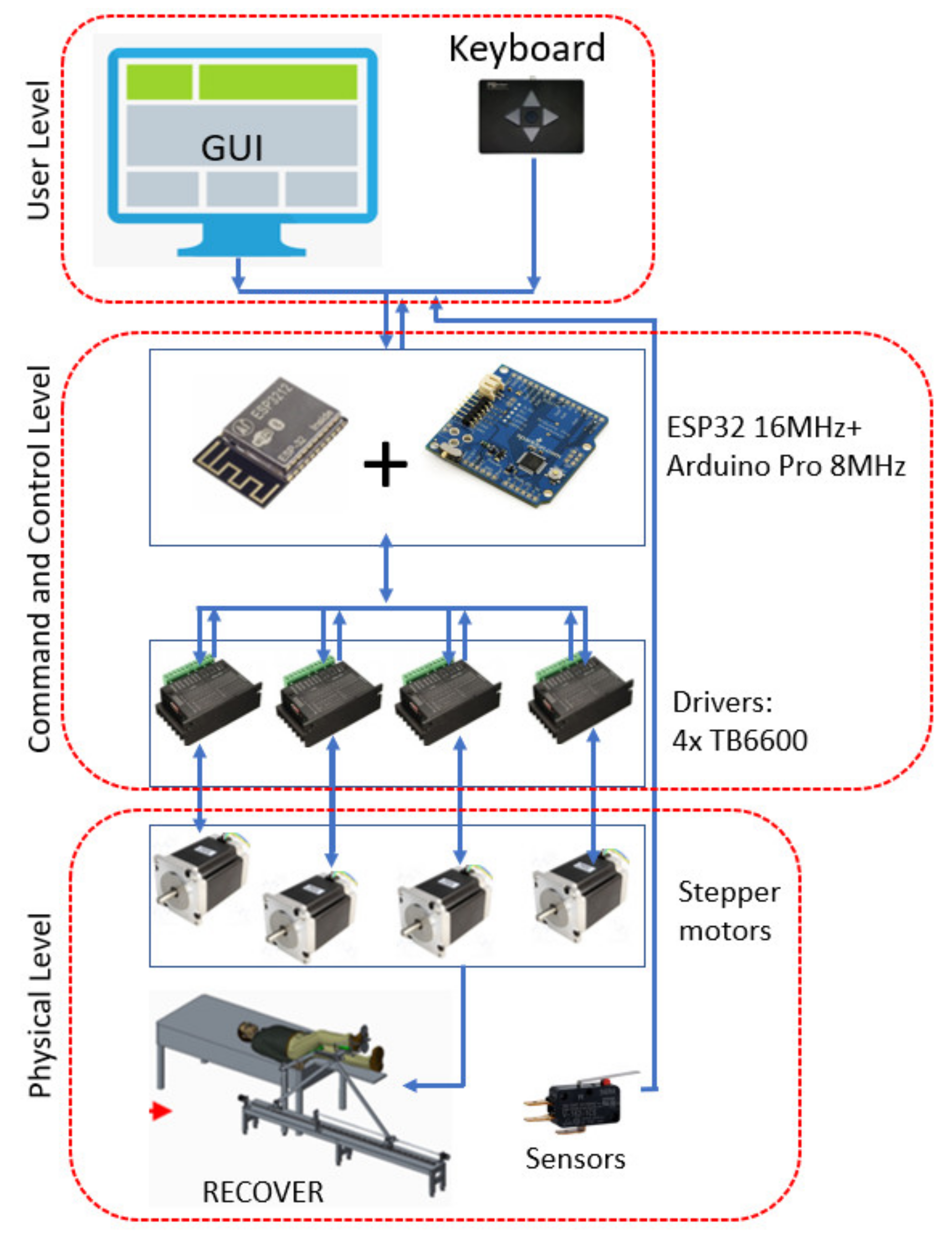
2.1.2. Robot Control System

Within this section the control system of RECOVER is presented. The control architecture of RECOVER is presented in Figure 3 and it is divided in three levels: user level, command-and-control level, and physical level.
The User Level consists of the user interface, which uses a PC that hosts a simple graphical user interface (GUI). For manual control, inputs to the robotic system can be made via the GUI or a 4-button micro keyboard, which allows for the selection of the desired motor, which is driven forward or backwards as long as the specific key is pressed. The desired motor can be selected using an LCD display that also controls the selection and storage of each motor’s working speed. This mode is used for testing patient spasticity, and at the same time manual control is required in case of emergency and the patient’s leg has to be guided in a safe position and detached from the robot. For rehabilitation procedure input data are type of motion, amplitude of the motion, speed of the motion, and the numbers of times the motion is repeated.
The Command-and-Control Level is comprised of an “Arduino Uno” board with an ATMega328P microcontroller operating at a frequency of 16 MHz and generating a control signal via a TB6600 driver to operate each individual motor.
The Physical Level consists of the mechanical structure and end-of-stroke micro switches. The microcontroller produces a symmetrical rectangular signal by increasing the voltage level of one module pin at equivalent intervals induced by a 1-s delay when waiting for the microcontroller to something. The desired command can be achieved on the PC connection line via its USB interface. The next step is to design a c control algorithm to operate the robot motors. To do so, a computer program was created that graphically displayed the robot configuration and user manual commands given as input. The test interface was created in Visual Basic and simulates the robot motions on the screen, including the “hip–knee–sole” positioning of the patient’s leg lying on the corresponding robot bed, which is carried out by the hip–knee module, as well as the control and visualization of the sole rotation movements (the Ankle Module), which are provided by the two motors and the moving part of the mechanism (the sole).
The robot’s motions are controlled by the operator using the robot control interface where stroke limits are imposed both within the developed control system (as the minimum and maximum number of impulses) and by external sensors mounted on each motion axis. The end-of-stroke microswitches placed at the end of each rail guide are used both for initialization purposes (for the homing procedure) as well as stroke limiters.
The simultaneous control of all motors can be accomplished relatively easy by applying the commands in the interrupt routine created by the Arduino module’s microcontroller timer every 20 microseconds so that each motor can be independently controlled in terms of speed and rotation path. As the TB6600 driver modules provide control to authorize the motor operation, namely the “Enable” signal, the number of digital commands of the robot becomes too large (2 serial contact signals for command and control from the monitor + 2 LCD monitor control signals + 4 manual “keyboard” execution signals + 4 motors × 3 control signals), therefore, due to its hardware shortcomings (the absence of input/output pins), the original Arduino board is unable to control any of the necessary signals. Furthermore, as the robot motors are located at significant distances from each other and from the power supply, interconnecting the modules on both the power side (12 V power supply and current absorbed in the order of 5–10 A) and the digital control component is difficult. Due to these factors, the RECOVER control system has been redesigned such that robot control is split into two microcontroller modules, one of which is an ESP32 WROOM module. This high-performance and programmable module takes control signals from the computer via its serial line on the USB connection, as in the classic Arduino modules. Commands to the robot can be generated in this manner using the internally implemented module and Bluetooth receiver/transmitter, or the control can be taken from a SMART phone using special software designed for this mode of wireless communication. This approach has been chosen as the default control mode if the command is provided by the phone or PC (standard serial Bluetooth communication or BLE on the internal interface or “USB Bluetooth dongle”). The ESP32 module can also generate motor control signals for motors m 1 and m 2 (hip–knee module) mounted on the base frame, ensuring proper orientation of the patient’s knee and ankle system. The ankle module host m 3 and m 4 motors, which are operated by a second lower-performance Arduino module, the “Arduino Pro Mini—The Simple”, which has been configured to operate at a low voltage of 3.3 V, similar to the ESP32, but at a low frequency (8 MHz), and is connected to the first ESP32 module via the regular serial line. Due to this signal load separation, the control pins are sufficient for the control of all robot motors, requiring only two wires to supply the 12 V moving part and two wires for the communication between the two modules. Figure 4 depicts the hardware interface’s block diagram. The ESP32 microcontroller has a firmware identical to the one introduced on the initial interface with Arduino, with each motor operated sequentially from the micro keyboard connected to the module, even though the motors can now operate concurrently.
The use of the function of authorization/inhibition of motor activity is an area that has received insufficient consideration. The stepper motors (one phase) are driven when the motors are turned on. If the motor does not turn, the power consumption that heats the motor has a braking effect (braking torque). It is necessary to see how the robot will maintain its working position without this braking torque in situations where the weight of the parts and the patient will induce unforeseen movements or give up the permission of rotations, in which case the braking torque disappears, and the heat of the motors will be at a lower degree.
Two microcontrollers connect with each other to form the control hardware. The first module is the ESP WROOM, which is used to power the hip–knee motors, and the second is the “Arduino Pro Mini—The Simple”, which is used to control the ankle module’s motors. Furthermore, the controller incorporates a Bluetooth receiver/transmitter, allowing power to be transferred to a smartphone through an app designed specifically for this wireless communication mode.
The control of the RECOVER robotic system is provided by the firmware implemented in the ESP32 micro controller. It ensures the taking over of the commands from the system keyboard, of the commands received on the primary serial interface (TX0, RX0-USB) and/or those received on the “Bluetooth” interface. The 16-character LCD display on 2 lines always displays the system status, on the secondary serial interface (TX2, RX2) the commands for the control of the ankle module driven by motors 3 and 4 are generated and on the digital lines DIR_1, PUL_1, and ENA_1 and DIR_2, PUL_2, and ENA_2 generates the commands for motors 1 and 2, taking over the state of the position sensors (end stroke microswitches, positive limit SP_1, SP_2 and negative limit SN_1, SN_2) in order to be able to identify the positions of the elements of the parallel rehabilitation robot system. In the generic firmware algorithm, it can be seen that the system, after starting, executes in infinite loop of the keyboard reading sequence, after which it takes over the commands arrived from the serial interfaces and after interpreting the received commands implemented by selecting the appropriate routine from the MENU.
The basic element in the menu is the control routine of the drive assembly of the two stepper motors that determines the position of the revolute joint R3 according to the X and Z directions, called SM_step, having the following control parameters:
  • The number of steps (step) executed by the selected motor, if this parameter is chosen 0 then the motor will rotate until the control button (forward or backward) is active (pressed), or for a positive value it will execute the specified number of steps;
  • Actuation speed given in (steps/sec), usually in the range 100–1200, the velocity sign in the expression determines the direction of rotation;
  • Motor selection: 1 selecting m 1 , 2 selecting m 2 , 3 selecting both motors that will rotate in the same direction, and 4 when both motors rotate but in opposite directions.
  • The ratio of driving speeds ranges from 1 to 7, with 1 indicating that the motor m 1 spins 3 times faster than m 2 , 2 indicating 2 times, 3 indicating 1.5 times (3/2), 4 indicating equal speeds, and 5, 6, and 7 indicating 2/3, 1/2, and 1/3 ratios, respectively.
This routine ensures the operation of the mechanism; all the desired movements will be achieved by calling it.
Other elements in the implemented menu list are routines that implement specific functions for executing commands, displaying messages, reading and writing serial interfaces, USB or Bluetooth, transmitting commands and receiving responses to/from the secondary module with m3 and m4 motors (Arduino Pro Mini module), 4Keys keyboard reading routine, and loading and reading numeric parameters in/from microsystem memory registers in string, long, integer, byte formats, etc.
Reading the keyboards is the simplest problem to solve; the four lines kb1–kb4 are read at a time, generating a numerical command code between 0 and 15, with 15 corresponding to no button pressed and 0 corresponding to all buttons pressed. The obtained code is interpreted after checking the serial readings from the computer (PC) or “Bluetooth” device (Android or IOS phone or tablet), text-type ASCII codes chosen for functions that can only be generated from intelligent devices, for example keyboard inhibition/reactivation command, generation of “movement scenarios” when a series of commands will be generated in order to operate the motors so that they generate pre-designed recovery programs, cyclic exercises, or random repetition.
For example, to isolate the motion of the revolute joint R k , the mechanism must be controlled in such a way that after the movement of the prismatic joints q 1 and q 2 , the position of the revolute joint R k stays fixed, the displacement generating only the variation of the angle φ k n e e . This is accomplished by creating basic motions (of the order of 0.5–2 mm in length) that are alternative or concomitant of the two motors m 1 and m 2 . This may be accomplished through computation when, for example, the movement of the rotation joint R 3 along the X axis with a selected elementary value is varied, the movement is made on the X axis, and the position of the rotation joint R k changes. In this intermediate position, a second elementary step is calculated, this time on the Z axis, such that the rotation joint R k returns to its initial fixed position. Another approach for generating complex exercises is to specify the motion in the table, with the values of the movement positions being taken over by a specific menu routine to generate the desired movement described in the table, and the values being transferred to the microcontroller memory for execution. These motions might be continuous, interrupted at varied times given in the table, or generated repetitively (cyclically) based on the therapist’s preference.
The current recovery system control solution was built using ESP32 and Arduino Pro Mini modules, respectively classic stepper motor drivers, TB6600 modules. The “firmware” solution is still under development and testing.
The next step is to validate the control system implemented in the experimental model of RECOVER, for this a comparison method between a simulation using the kinematic model of the robot and set of data extracted from the experimental model is used [39,40,41,42,43,44,45].

2.2. Experimental Validation of the RECOVER Control System

For validating the control system of the RECOVER, a series of experimental tests were performed. A number of 8 healthy subjects were selected for the tests; their characteristics are given in Table 1.
The tests were carried out with the participants’ written consent, in accordance with the principles of the Helsinki Declaration (even though they were carried out in laboratory conditions), and after a lengthy explanation of the testing procedure, the instruments used, the targeted motions, the duration of the procedure, and the possible risks involved. Before performing the tests, a rehabilitation protocol for testing the functionality of the robotic system was developed:
  • The subject must lay on the bed’s edge, with the pelvis located at the end of the bed, so that limb movement is possible beyond the upper side of the bed.
  • Human hip rotational axes and robot hip joint rotational axes must be collinear.
  • The length of the robot’s femoral link must be calibrated to correspond to the anthropometric length of the thigh, so that the rotational knee joint axes of the human lower limb and the axes of knee and robotic knee joint are collinear.
  • The lower limb that will not be subjected to rehabilitation training will be held by a support installed in the bed’s expansion, ensuring that it remains completely horizontal.
  • The lower limb undergoing medical recovery therapy will be put on thigh support, which will be tied on with braces, and the lower leg will be placed on lower leg support, which will also be tied on with straps.
  • Once the thigh and lower leg are secured to their respective supports, the foot is positioned within the ankle module, which is secured to the lower limb support. The adjustment length of connection requires the sole to be secured to the sole support, and the foot is attached to the sole support with Velcro straps.
  • The rehabilitation process is started based on the advice of the physiotherapist.
  • The robot performs the rehabilitation motions with the patient attached.
  • When the rehabilitation process is completed, the robot returns to the start position, the lower limb will be disconnected from the sole support, lower leg support and thigh straps and the subject may end the rehabilitation process.
Using the RECOVER robotic system, the following motions were performed during the experimental tests:
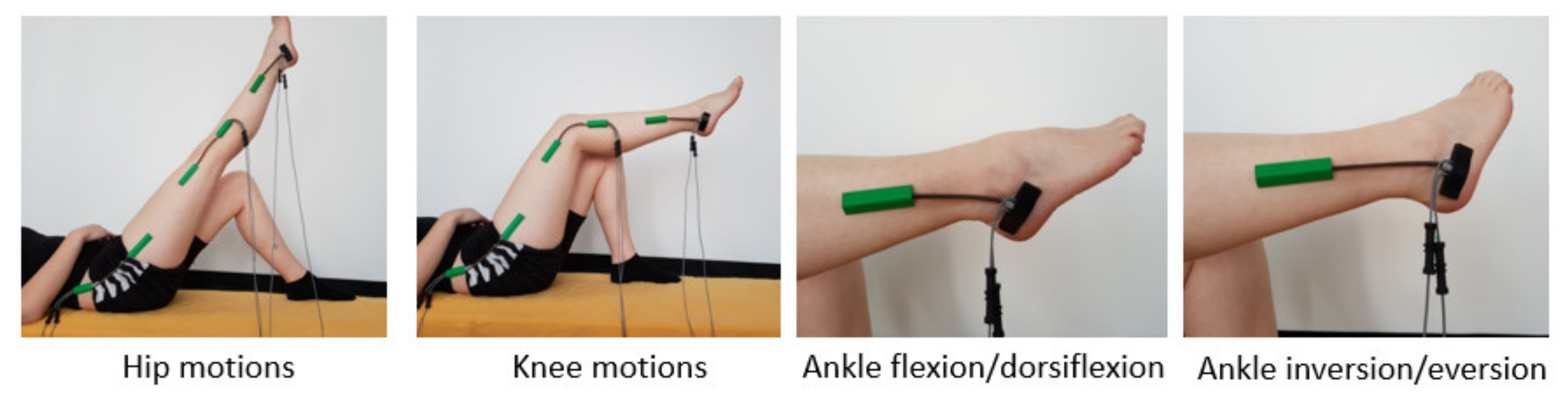
  • Hip flexion/extension.
  • Knee flexion/extension.
  • Ankle dorsiflexion/plantar flexion.
  • Ankle inversion/eversion.
The tests were performed following the testing protocol defined above, and indications coming from the physiotherapists. As the subjects were healthy, no baseline assessment was required, and the physiotherapist performed only a minor health state assessment in order to allow the subject to participate the tests.
The following timeline was defined during the experimental tests and respected during the entire testing of the robotic system:
  • Participant is laying down on the adjustable bed, the robotic system is placed on the right side of bed; thus, the subject of test will place his right leg on the robotic device (Figure 5).
  • Each subject is asked to place themselves comfortably and in a correct position on the robotic device after sterilizing the robot elements that come into direct contact with the test participant’s body;
  • The subject’s foot is placed on the ankle module support composed from a lower leg support, sole support, and heel support, once the foot is positioned in the ankle module, it is secured with Velcro straps;
  • Ten repetitions are performed for each rehabilitation training motion;
  • First rehabilitation motion tested is hip flexion/extension; the leg is raised in sagittal plane;
  • Before executing the next motion, the robot is returned to its starting position;
  • The second rehabilitation motion tested is knee flexion/extension executed also in sagittal plane;
  • After knee flexion/extension exercises is performed, the robot is returned again in the starting position.
  • The third motion performed is dorsiflexion/plantar flexion, this motion is also in sagittal plane.
  • The last motion is ankle inversion/eversion performed in the frontal plane.
Several screen-captured images were taken during the experimental tests. Figure 6 presents screen-captured images from the hip rehabilitation motion. Figure 7 presents screen-captured images taken during the knee motion rehabilitation. Figure 8 and Figure 9 presents screen-captured images during ankle rehabilitation.
The participants became more comfortable with the robotic system after a certain number of repetitions and as they became more familiar activities and motions.
During the experimental tests, the state of the patient was continuously checked by the physiotherapist.
An external measuring system [46] was used for measuring the amplitude achieved during the rehabilitation task. The sensor system is composed of several goniometers placed on the subject skin allowing an accurate reading of angular displacement during motion of the anatomical joint. The goniometers are double-axis type that measures angles in up two planes of movement; they have two separate connections one output connection measures flexion/extension, while the other measures radial/ulnar deviation. Simply connect one channel for measuring a single-axis joint, such as the knee or elbow, or when measuring a single plane of a twin-axis joint. The double-axis goniometers are available as wireless or wired (as they were the goniometers use in the presented tests). As a technical specification the following can be mentioned: the resolution +0.1° in a range of 180°, the accuracy is ±2° measured in a range of 90°, the repeatability is 1° measured over a range of 90°, and the full scale is ±180°. Figure 10 shows the position of the goniometers placed on the experiment subjects. The biosensors mounted on the subject’s body (on the lower limb) were selected as follows:
  • For the hip joint, a dual axis goniometer (for the measurement of the hip motion amplitudes in two perpendicular planes), positioned laterally (SG150);
  • For the knee joint, a similar goniometer was used even though the motion is performed in a single plane, thus only the signal from one axis will be interpreted (SG150);
For the ankle joint a special dual axis goniometer is used (SG110A).
Angular displacements recorded during the experimental tests were further used to check the functional validation of RECOVER.

3. Results

Displacements, velocities, and accelerations were recorded during the experimental tests. In order to validate the functionality of the robotic system and at the same time to test the control system, data recorded is compared with a mathematical simulation performed in MATLAB [30] using the kinematic model of RECOVER. The two sets of data are graphically represented using the same coordinate system with the help of MATLAB. Data obtained from the mathematical simulation is plotted and the data obtained from experimental tests is superposed over the simulation data. Figure 11 presents the overlapping of the hip set of data. The first plot represents the angular displacement (green color) obtained from the simulation, and the blue discontinuous line represents angular displacement obtained during the experimental tests. The second plot represents the hip motion velocity (red color) obtained from the simulation, and the blue discontinuous line represents angular velocity obtained during the experimental tests. The third plot represents the hip motion acceleration (yellow color) obtained from the simulation, and the blue discontinuous line represents angular acceleration obtained during the experimental tests. The comparison resulted in no significant difference between the two sets of data, validating the functionality of the hip rehabilitation module and at the same time the stability of the control system during the rehabilitation procedure.
Figure 12 illustrates the knee joint angular displacement, knee joint velocity, and knee joint acceleration during the knee flexion training. The angular displacement, velocity, and acceleration of robot simulated motions in MATLAB are almost identical to the motion results obtained during the robotic rehabilitation training and measured with the external twin-axis goniometers, the results being compared using RMSE statistical functions; this indicates that the design goal of robot was achieved.
Figure 13 presents the plantar flexion/dorsiflexion motion training, while Figure 14 presents the ankle inversion/eversion motion training performed with the ankle module; here, the results of the MATLAB simulation and ankle module were compared; the same behavior was obtained.
The amplitude of motion, max velocity, and the number of repletion are input data for the system from the user interface. The input amplitudes are computed to be achieved with the maximum velocity given in the interface, thus when the motion starts, motors achieve the input velocity by accelerating with a given acceleration ± 5   deg / sec 2 . When the desired velocity is achieved, the acceleration drops to zero until the motion is inversed. The system uses maximum acceleration to reach the motion and uses constant speed until the motion is inversed. The graphic from Figure 15 shows the error obtained between simulation and experimental run. Additionally, Table 2 presents the mean and standard deviation for each motion error. The functionality of the robotic system is considered validated when the difference between the two sets of data is insignificant, as is illustrated in Figure 15 and Table 2.

4. Discussion

The presented robotic system was built based on design specification trying to meet the rehabilitation motions of the lower limb, as the hip–knee module moves in the sagittal plane, the hip joint’s adduction and abduction movements are not possible. However, the flexion/extension of hip and knee flexion have good range of motion: −25° for extension and 85° of flexion. The robot system satisfied the required rehabilitation motions; with the help of twin-axis goniometers [46], the lower limb range of motions were measured during RECOVER tests. Table 3 shows the lower limb range of motions acquired by patients during tests.
Table 3 values represent the calculated mean of the ROM values measured (using a goniometer) for all healthy subjects that took part in the laboratory tests. The measurements have not been achieved using only the robot. The ROM of the ankle inversion has been measured as stated above (using a goniometer and the healthy subjects), but as the ankle module’s mechanical construction is symmetric, it can be inferred that the ankle eversion ROM values can be equal (regarding the capabilities of RECOVER) with the ones of the ankle inversion. Nevertheless, the control system limits the maximum ROM of each joint to the values presented by the CDC [47] (males and females age group age 45–69), while the control interface allows the user to specify the exact values during training exercises.
The control system architecture is composed by three levels: user level, command and control level, and physical level. The user level consists of the user interface, that hosts the graphical user interface (GUI), but during the tests the manual mode was used for a better control of speed and motion amplitudes, and to prevent any non-conformities in operation, so that the patients’ physical integrity is not endangered and their degree of physical comfort is not affected. Three therapy scenarios are currently being developed: one for hip joint movement rehabilitation, one for knee joint movement rehabilitation, and one for both motion rehabilitation combined.
In order to make the autonomous control of ankle module motions, two scenarios were investigated, the first is when the motors rotate in the same direction having the same speed; the ankle module performs plantar flexion/dorsiflexion. The second scenario is when the motors run with the same velocity but rotating in opposite directions; in this case, the ankle module makes inversion/eversion motions. The control of desired motions is based on how long the motors are working in same direction or opposite; to prevent any functional non-conformities at the end of linear stroke, microswitches are placed.
Regarding the mechanical design aspects of the robotic system, the structure of the robot is rigid; the links are strong and lightweight, built from aluminum alloy. The adjustability of the hip–knee module and the ankle module allow the robotic system to fit to a variety of anthropometric sizes. From an ergonomic point of view, the robot satisfied the design technical characteristics defined at the beginning of the research. The participants to the experimental tests felt comfortable and safe during rehabilitation procedure. The design and the functionality of the robotic system was generally accepted both by the physiotherapist supervising the experimental test and the people testing the robot systems.
The participants filled in a feedback form which shows their opinion about the experience with the parallel rehabilitation robot. They were also asked to explain the robotic rehabilitation system’s positives and the aspects that should be improved on in a few words.
The robotic system behavior during experimental tests was satisfactory for the physiotherapists, the motion amplitudes achieved being suitable for lower limb rehabilitation of bed-ridden patients. The mathematical model was successfully implemented within the control system of RECOVER and there were no significant differences between the virtual simulation of the kinematic model and the data obtained from the experimental model during functioning. The results have encouraged the authors to go further with their research, and prepare the robotic system for a first set of clinical trials after a multimodal, user-friendly user interface is implemented.

5. Conclusions

The developed robot control behaved as expected during the experimental tests, providing valuable data for the further development of the robotic system. The modules of the robotic system are controlled by two different controllers, allowing them to function independently or simultaneously. Laboratory tests have been carried out for demonstrating the robustness and effectiveness of the proposed control system. Experimental tests have been held in safe conditions under physiotherapeutic supervision following an informed consent by the participants. During the tests, the RECOVER robotic system demonstrated a reliable behavior and a good match with the proposed numerical simulations. Furthermore, patients who took part in the experiments gave positive feedback without reporting any discomfort. The tests results were compared with data from virtual simulations to validate the experimental model functionality and control stability. Further clinical studies will be planned in future for investigating additional aspects, such as the performance on a large variety of patients, the role of the physiotherapist during the tests, and the implementation of various medical rehabilitation protocols.

Author Contributions

Conceptualization, I.N., P.T., D.P. and G.C.; Methodology P.T., B.G. and I.N.; Mathematical validation P.T. and B.G.; Resources, S.A., I.N., B.G., P.T., T.A. and A.B. Writing—Original Draft Preparation I.N.; Writing—Review and Editing, D.P., G.C., B.G. and P.T. Supervision, D.P., B.G. and G.C.; and Project Administration, D.P. and G.C. All authors have read and agreed to the published version of the manuscript.

Funding

This work was supported by a grant from the Romanian Ministry of Research and Innovation, CCCDI—UEFISCDI, project number PN-III-P2-2.1-PED-2019-3022/546PED/2020 (NeuroAssist) within PNCDI III and by the project POCU/380/6/13/123927—ANTREDOC, “Entrepreneurial competencies and excellence research in doctoral and postdoctoral studies programs”, co-479 funded from the European Social Fund through the Human Capital Operational Program 2014–480 2020.

Institutional Review Board Statement

Ethical review and approval were waived for this study, due to the fact that the validation tests were intended only to assess the feasibility and range of motion of RECOVER for the rehabilitation of the lower limb, being achieved in laboratory conditions, which required the participation of volunteers, healthy subjects. Furthermore, the volunteers have given their written consent after being informed about the test circumstances and the robotic system’s operation, as well as any hazards or safety concerns that may arise during the tests.

Informed Consent Statement

Informed consent was obtained from all subjects involved in the study.

Data Availability Statement

The data presented in this study are available on request from the corresponding author. The data are not publicly available due to [privacy].

Conflicts of Interest

The authors declare no conflict of interest.

References

  1. Robots Association. Multi Annual Roadmap for Robotics in Europe; Robots Association: Préverenges, Switzerland, 2017. [Google Scholar]
  2. Feigin, V.L.; Norrving, B.; Mensah, G.A. Global Burden of Stroke. Circ. Res. 2017, 120, 439–448. [Google Scholar] [CrossRef] [PubMed]
  3. Wafa, H.A.; Wolfe, C.D.A.; Emmett, E.; Roth, G.A.; Johnson, C.O.Y.; Wang, Y. Burden of Stroke in Europe. Stroke 2020, 51, 2418–2427. [Google Scholar] [CrossRef] [PubMed]
  4. Gorelick, P.B. The global burden of stroke: Persistent and disabling. Lancet Neurol. 2019, 18, 417–418. [Google Scholar] [CrossRef] [Green Version]
  5. Lloyd-Jones, D.; Adams, R.J.; Brown, T.M.; Carnethon, M.; Dai, S.; de Simone, G.; Ferguson, T.B.; Ford, E.; Furie, K.; Gillespie, C.; et al. Heart disease and stroke statistics—2010 update: A report from the American heart association. Circulation 2010, 121, e46–e215. [Google Scholar] [PubMed]
  6. Díaz, I.; Gil, J.J.; Sánchez, E. Lower-Limb Robotic Rehabilitation: Literature Review and Challenges. J. Robot. 2011, 2011, e759764. [Google Scholar] [CrossRef]
  7. Esquenazi, A.; Packel, A. Robotic-assisted gait training and resto ration. Am. J. Phys. Med. Rehabil. 2012, 91, S228–S231. [Google Scholar] [CrossRef] [PubMed]
  8. Banala, S.K.; Kim, S.H.; Agrawal, S.K.; Scholz, J.P. Robot assisted gait training with active leg exoskeleton (ALEX). IEEE Trans. Neural Syst. Rehabil. Eng. 2009, 17, 2–8. [Google Scholar] [CrossRef] [PubMed]
  9. Gonçalves, R.; Rodrigues, L. Development of nonmotorized mechanisms for lower limb rehabilitation. Robotica 2021, 1–18. [Google Scholar] [CrossRef]
  10. Wang, L.; Chang, Y.; Zhu, H. Internal Model Control and Experimental Study of Ankle Rehabilitation Robot. Robotica 2020, 38, 940–956. [Google Scholar] [CrossRef]
  11. Wang, Y.; Wang, K.; Chai, Y.; Mo, Z.; Wang, K. Research on mechanical optimization methods of cable-driven lower limb rehabilitation robot. Robotica 2021, 1–16. [Google Scholar] [CrossRef]
  12. Colombo, G.; Joerg, M.; Schreier, R.; Dietz, V. Treadmill training of paraplegic patients using a robotic orthosis. J. Rehabil. Res. Dev. 2000, 37, 693–700. [Google Scholar] [PubMed]
  13. Freivogel, S.; Mehrholz, J.; Husak-Sotomayor, T.; Schmalohr, D. Gait training with the newly developed “LokoHelp”-system is feasible for non-ambulatory patients after stroke, spinal cord and brain injury. A feasibility study. Brain Inj. 2008, 22, 625–632. [Google Scholar] [CrossRef] [PubMed]
  14. Freivogel, S.; Schmalohr, D.; Mehrholz, J. Improved walking ability and reduced therapeutic stress with an electromechanical gait device. J. Rehabil. Med. 2009, 41, 734–739. [Google Scholar] [CrossRef] [PubMed] [Green Version]
  15. Banala, K.; Agrawal, S.K.; Scholz, J.P. Active Leg Exoskeleton (ALEX) for gait rehabilitation of motor-impaired patients. In Proceedings of the 10th IEEE International Conference on Rehabilitation Robotics (ICORR ’07), Noordwijk, The Netherlands, 12–15 June 2007; pp. 401–407. [Google Scholar]
  16. Hesse, S.; Uhlenbrock, D. A mechanized gait trainer for restoration of gait. J. Rehabil. Res. Dev. 2000, 37, 701–708. [Google Scholar] [PubMed]
  17. Schmidt, H. Hapticwalker—a novel haptic device for walking simulation. In Proceedings of the EuroHaptics Conference, Munich, Germany, 5–7 June 2004; pp. 60–67. [Google Scholar]
  18. Chen, S.; Wang, Y.; Li, S.; Wang, G.; Huang, Y.; Mao, X. Lower limb rehabilitation robot. In Proceedings of the ASME/IFToMMInternational Conference on Reconfigurable Mechanisms and Robots (ReMAR ’09), London, UK, 22–24 June 2009; pp. 439–443. [Google Scholar]
  19. Yoon, J.; Novandy, B.; Yoon, C.H.; Park, K.J. A 6-DOF gait rehabilitation robot with upper and lower limb connections that allows walking velocity updates on various terrains. IEEE/ASME Trans. Mechatron. 2010, 15, 201–215. [Google Scholar] [CrossRef]
  20. Peshkin, M.; Brown, D.A.; Santos-Munne, J.J.; Makhlin, A.; Lewis, E.; Colgate, J.E.; Patton, J.; Schwandt, D. KineAssist: A robotic overground gait and balance training device. In Proceedings of the 9th IEEE International Conference on Rehabilitation Robotics (ICORR ’05), Evanston, IL, USA, 28 June–1 July 2005; pp. 241–246. [Google Scholar]
  21. Goffer, A. Gait-Locomotor Apparatus. U.S. Patent Number 7,153,242, 26 December 2006. [Google Scholar]
  22. Kawamoto, H.Y.; Sankai, H. Power assist system hal-3 for gait disorder person. In Proceedings of the 8th International Conference on Computers Helping People with Special Needs, London, UK, 15–20 July 2002; pp. 196–203. [Google Scholar]
  23. Schmitt, C.; M’etrailler, P.; Al-Khodairy, A.; Brodard, R.; Fournier, J.; Bouri, M.; Clavel, R. The motion maker: A rehabilitation system combining an orthosis with closed-loop electrical muscle stimulation. In Proceedings of the 8th Vienna International Workshop on Functional Electrical Stimulation, Vienna, Austria, 10–13 September 2004; pp. 117–120. [Google Scholar]
  24. Girone, M.; Burdea, G.; Bouzit, M.; Popescu, V.; Deutsch, J.E. Stewart platform-based system for ankle telerehabilitation. Auton. Robot. 2001, 10, 203–212. [Google Scholar] [CrossRef]
  25. Roy, A.; Krebs, H.I.; Patterson, S.L.; Judkins, T.N.; Khanna, I.; Forrester, L.W.; Macko, R.M.; Hogan, N. Measurement of human ankle stiffness using the anklebot. In Proceedings of the 10th IEEE International Conference on Rehabilitation Robotics, (ICORR ’07), Noordwijk, The Netherlands, 12–15 June 2007; pp. 356–363. [Google Scholar]
  26. Melo, N.; Dórea, C.; Alsina, P.; Araújo, M. Joint trajectory generator for powered orthosis based on gait modelling using PCA and FFT. Robotica 2018, 36, 395–407. [Google Scholar] [CrossRef]
  27. Huo, W.; Arnez-Paniagua, V.; Ding, G.; Amirat, Y.; Mohammed, S. Adaptive Proxy-Based Controller of an Active Ankle Foot Orthosis to Assist Lower Limb Movements of Paretic Patients. Robotica 2019, 37, 2147–2164. [Google Scholar] [CrossRef]
  28. Zhou, X.; Liu, G.; Han, B.; Li, H.; Zhang, L.; Liu, X. Different Prevention and Treatment Strategies for Knee Osteoarthritis (KOA) with Various Lower Limb Exoskeletons—A Comprehensive Review. Robotica 2021, 39, 1345–1367. [Google Scholar] [CrossRef]
  29. Vaida, C.; Birlescu, I.; Pisla, A.; Ulinici, I.; Tarnita, D.; Carbone, G.; Pisla, D. Systematic Design of a Parallel Robotic System for Lower Limb Rehabilitation. IEEE Access 2020, 8, 34522–34537. [Google Scholar] [CrossRef]
  30. Gherman, B.; Birlescu, I.; Nicolae, P.; Carbone, G.; Tarnita, D.; Pisla, D. On the singularity-free workspace of a parallel robot for lower-limb rehabilitation. Proc. Rom. Acad. 2019, 20, 383–391. [Google Scholar]
  31. Di Natali, C.; Poliero, T.; Sposito, M.; Graf, E.; Bauer, C.; Pauli, C.; Ortiz, J. Design and Evaluation of a Soft Assistive Lower Limb Exoskeleton. Robotica 2019, 37, 2014–2034. [Google Scholar] [CrossRef] [Green Version]
  32. Nadas, I.; Gherman, B.; Birlescu, I.; Bogateanu, R.; Banica, A.; Carbone, G.; Pisla, D. Dynamic balancing of RECOVER robotic system. IOP Conf. Ser. Mater. Sci. Eng. 2020, 997, 12083. [Google Scholar] [CrossRef]
  33. Gherman, B.; Nadas, I.; Tucan, P.; Carbone, G.; Pisla, D. Design and Simulation of Gait Rehabilitation Parallel Robotic System. In New Advances in Mechanisms, Mechanical Transmissions and Robotics; Lovasz, E.C., Maniu, I., Doroftei, I., Ivanescu, M., Gruescu, C.M., Eds.; MTM&Robotics, Mechanisms and Machine Science; Springer: Cham, Switzerland, 2020; Volume 88. [Google Scholar] [CrossRef]
  34. Gherman, B.; Birlescu, I.; Tucan, P.; Vaida, C.; Pisla, A.; Pisla, D. Modelling and simulation of a robotic system for lower limb rehabilitation. In Proceedings of the ASME 2018 International Design Engineering Technical Conferences and Computers and Information in Engineering Conference, Volume 5B: 42nd Mechanisms and Robotics Conference (V05BT07A083), Quebec City, QC, Canada, 26–29 August 2018; ASME: New York, NY, USA. [Google Scholar] [CrossRef]
  35. Nadas, I.; Gherman, B.; Albert, S.; Surducan, V.; Pop, N.; Carbone, G.; Banica, A.; Pisla, D. Design and control of Recover Rehabilitation Parallel Robot. In Proceedings of the 1st International Conference on Advanced Research in Engineering, CARE 2020, Tokyo, Japan, 10–30 November 2020; Tarnita, D., Dumitru, N., Paraschiv, G., Dumitru, I., Eds.; Universitaria Craiova: Craiova, Romania, 2020; pp. 3–10. [Google Scholar]
  36. Gherman, B.; Birlescu, I.; Puskas, F.; Pisla, A.; Carbone, G.; Tucan, P.; Banica, A.; Pisla, D. A Kinematic Characterization of a Parallel Robotic System for Lower Limb Rehabilitation. In Mechanisms and Machine Science; Corves, B., Wenger, P., Hüsing, M., Eds.; EuCoMeS 2018; Springer: Cham, Switzerland, 2019; Volume 59. [Google Scholar] [CrossRef]
  37. Nadas, I.; Gherman, B.; Albert, S.; Surducan, V.; Pop, N.; Carbone, G.; Banica, A.; Pisla, D. Innovative Development of a Parallel Robotic System for Lower Limb Rehabilitation; Series: Applied Mathematics, Mechanics, and Engineering; Acta Technica Napocensis: Cluj-Napoca, Romania, 2021; Volume 64, pp. S1–S2. ISSN 2393–2988. Available online: https://atna-mam.utcluj.ro/index.php/Acta/article/view/1537 (accessed on 15 September 2021).
  38. Pisla, D.; Gherman, B.; Nadas, I.; Pop, N.; Craciun, F.; Tucan, P.; Vaida, C.; Carbone, G.; Birlescu, I.; Plitea, N. Innovative Parallel Robot for Medical Recovery of the Lower Limbs. Patent Numbers: RO133815-A0; RO133815-A3, 30 December 2020. [Google Scholar]
  39. Vaida, C.; Pisla, D.; Schadlbauer, J.; Husty, M.; Plitea, N. Kinematic Analysis of an Innovative Medical Parallel Robot Using Study Parameters. In New Trends in Medical and Service Robots; Wenger, P., Chevallereau, C., Pisla, D., Bleuler, H., Rodić, A., Eds.; Mechanisms and Machine Science; Springer: Cham, Switzerland, 2016; Volume 39. [Google Scholar] [CrossRef]
  40. Gherman, B.; Vaida, C.; Pisla, D.; Plitea, N.; Gyurka, B.; Lese, D.; Glogoveanu, M. Singularities and workspace analysis for a parallel robot for minimally invasive surgery. In Proceedings of the 2010 IEEE International Conference on Automation, Quality and Testing, Robotics (AQTR), Cluj-Napoca, Romania, 28–30 May 2010; pp. 1–6. [Google Scholar] [CrossRef]
  41. Vaida, C.; Plitea, N.; Gherman, B.; Szilaghyi, A.; Galdau, B.; Cocorean, D.; Covaciu, F.; Pisla, D. Structural Analysis and Synthesis of Parallel Robots for Brachytherapy. In New Trends in Medical and Service Robots; Mechanisms and Machine Science; Pisla, D., Bleuler, H., Rodic, A., Vaida, C., Pisla, A., Eds.; Springer: Cham, Switzerland, 2014; Volume 16. [Google Scholar] [CrossRef]
  42. Schonstein, C. Kinematic Control Functions for a Serial Robot Structure Based on the Time Derivative Jacobian Matrix; Series: Applied Mathematics and Mechanics; Acta Technica Napocensis: Cluj-Napoca, Romania, 2018; ISSN 1221-5872. [Google Scholar]
  43. Vaida, C.; Carbone, G.; Major, K.; Major, Z.; Plitea, N.; Pisla, D. On Human Robot Interaction Modalities in the Upper Limb Rehabilitation after Stroke; Series: Applied Mathematics Mechanics and Engineering; Acta Technica Napocensis: Cluj-Napoca, Romania, 2017; Volume 60, pp. 91–102. [Google Scholar]
  44. Vaida, C.; Pisla, D.; Plitea, N.; Gherman, B.; Gyurka, B.; Stancel, E.; Hesselbach, J.; Raatz, A.; Vlad, L.; Graur, F. Development of a control system for a parallel robot used in minimally invasive surgery. IFMBE Proc. 2009, 26, 171–176. [Google Scholar]
  45. Husty, M.; Birlescu, I.; Tucan, P.; Vaida, C.; Pisla, D. An algebraic parameterization approach for parallel robots analysis. Mech. Mach. Theory 2019, 140, 245–257. [Google Scholar] [CrossRef]
  46. Biometrics Ltd. Available online: https://www.biometricsltd.com/ (accessed on 18 September 2021).
  47. Centers for Disease Control and Prevention. Normal Joint Range of Motion Study. Available online: https://www.cdc.gov/ncbddd/jointrom/index.html (accessed on 8 October 2021).
Figure 1. The kinematic scheme of hip–knee module.
Actuators 10 00277 g001
Figure 2. The kinematic scheme of ankle module transposed on the 3D CAD model.
Actuators 10 00277 g002
Figure 3. Control system architecture of RECOVER.
Actuators 10 00277 g003
Figure 4. RECOVER hard drive block diagram [37] (image credit copyright C BY-NC-ND license (Attribution-Non Commercial-No Derivs).
Actuators 10 00277 g004
Figure 5. Starting position for lower limb rehabilitation.
Actuators 10 00277 g005
Figure 6. Screenshots during hip rehabilitation.
Actuators 10 00277 g006
Figure 7. Screenshots during knee rehabilitation.
Actuators 10 00277 g007
Figure 8. Screenshots during knee rehabilitation.
Actuators 10 00277 g008
Figure 9. Screenshots during ankle flexion/dorsiflexion rehabilitation.
Actuators 10 00277 g009
Figure 10. Biosensors mounted on subject’s leg for each rehabilitation motion [29] (image credit copyright Attribution 4.0 International (CC BY 4.0)).
Actuators 10 00277 g010
Figure 11. Graphical representation of hip module (displacement, velocity, and acceleration).
Actuators 10 00277 g011
Figure 12. Graphical representation of knee module (displacement, velocity, and acceleration).
Actuators 10 00277 g012
Figure 13. Graphical representation of ankle flexion/dorsiflexion module (displacement, velocity, and acceleration).
Actuators 10 00277 g013
Figure 14. Graphical representation of ankle inversion/eversion module (displacement, velocity, and acceleration).
Actuators 10 00277 g014
Figure 15. Recorded error between simulation and experimental tests.
Actuators 10 00277 g015
Table 1. Main characteristics of experimental tests participants.
Subject No.GenderAge (Years)Weight (kg)Height (cm)
1Female4453162
2Female3655172
3Female3553163
4Male3068173
5Male3470178
6Male4076175
7Male3189184
8Male4280184
Table 2. Mean and standard deviation for each motion error.
Hip MotionKnee MotionAnkle Flex/Ext MotionAnkle Inv/Ev. Motion
0.0539 ± 0.02960.0517 ± 0.02940.0494 ± 0.2810.0481 ± 0.0297
Table 3. RECOVER Range of motions.
Rehabilitation Motions(°)
Hip flexion85°
Hip extension−25°
Knee flexion118°
Knee extension
Ankle dorsiflexion−25°
Ankle plantar flexion41°
Ankle inversion−25°
Ankle eversion25°
Publisher’s Note: MDPI stays neutral with regard to jurisdictional claims in published maps and institutional affiliations.

