
Motion Control System Design for a Flying-Type Firefighting System with Water Jet Actuators


1
The Industrial Science Technology Research Center, Pukyong National University, Nam-gu, Busan 48513, Korea
2
Department of Chassis and Body, Ho Chi Minh City University of Technology and Education, Ho Chi Minh City 700000, Vietnam
3
Department of Mechanical System Engineering, Pukyong National University, Nam-gu, Busan 48513, Korea
*
Authors to whom correspondence should be addressed.
Actuators 2021, 10(10), 275; https://doi.org/10.3390/act10100275
Submission received: 27 September 2021
/
Revised: 12 October 2021
/
Accepted: 15 October 2021
/
Published: 17 October 2021
(This article belongs to the Section Aircraft Actuators)
Abstract
:This paper presents the design and modeling of a flying-type fire extinguishing system. Fire accidents present very hazardous environments, and firefighters are in danger of losing their lives while putting out the fire. Strict safety measures should be considered to guarantee safe working conditions for firefighters, which is not the case every time, as fatalities and casualties are still being recorded. For this reason, a novel fire extinguishing system is proposed to provide more safe firefighting and survivor searches. The system studied in this paper is a pilot model that consists of a water jet-based actuation system to control the flying motion of the robot. The dynamic model of this flying robot is derived using the actuation forces, water jet system characteristics, and related information. The mathematical system model is detailed, a sliding-mode control system and a proportional-integral-derivative controller are designed, and comparative simulation tests are carried out.
1. Introduction
In this research, a new fire extinguishing system that can suppress flames quickly and efficiently is studied. Fire accidents are unfortunate disasters that damage properties and endanger the lives of people, including first responders. In recent years, the risk of public safety and the difficulty of responding to such incidents is gradually increasing due to complex and large-scale buildings, such as airports, stadiums, exhibition halls, warehouses, and other vital construction areas. The risk of firefighters and victims getting secluded and losing their lives due to post-blast explosions and structures collapsing is very high, which makes it difficult to perform active firefighting tasks.
In the case of a fire onboard a ship, it is difficult to suppress the flames due to the unstable environment surrounding the ship (mainly waves), and it is best to simply direct the stream of water from a distance. And unlike land fires, the fire progresses rapidly depending on the materials constituting the ship hull. For instance, in the case of steel ships, it is difficult to approach the fire to put it out, due to high temperatures. Initially, if the fire suppression is deemed difficult, the firefighting personnel must go to the fire scene to search for and rescue survivors, a task that is carried out at risk. However, it is extremely difficult to quickly respond because of all the risk factors, which makes it difficult to reduce the degree of the damage caused by the response delay.
Various methods and technologies have been devised for rapid-fire suppression while minimizing the imminent damages bound to occur, but they are not to the level that they can respond adequately, quickly, and safely. Therefore, remote-controlled and autonomous fire extinguishing techniques became an active research area that aims to improve the efficacy of firefighting, fire suppression, and to reduce firefighter injuries and deaths. These systems may also increase the efficiency of firefighting tasks through advanced vision applications and additional sensors to support looking for survivors in low-visibility environments.
Though for small-scale fires many of the current robots developed for such outcomes are remotely controlled. For example, P. Liljeback et al. [1] suggested a water-powered actuation system enabling a fire hose to move like a snake and perform the fire intervention on its own. The shipboard autonomous firefighting robot (SAFFiR) is one of the earlier humanoid robots that helped researchers as a support tool in inspecting and suppressing fires aboard naval vessels [2]. However, for large-scale fires or when the flames have already engulfed the area, deploying such technologies is impossible. Subsequently, other techniques have been developed to fight such fire and suppress it. A typical example is a ground-type firefighting robot equipped with a caterpillar track or multiple wheels to perform fire suppression tasks even in areas where firefighters cannot enter, such as obstacles and rough roads [3]. Some commercial products have been launched, such as the remote-controlled Colossus robot in France [4] and Thermite RS1 and Thermite RS3 in the USA [5]. However, due to the lack of mobility and clear vision in underground and complex structures, the use of such technologies is limited to specific fire sites.
Recently, research studies on indoor and outdoor fire suppression systems using unmanned aerial vehicles (UAV) [6,7,8] and drones [9,10] are being actively conducted for this purpose. However, due to the characteristics of UAVs and drones, it is difficult and even aggravating to get them close to the fire and ignition locations, due to the airflow resulting from the rotor blades that may cause the flames to spread to neighboring areas. In other words, even if a drone is used in the process of suppressing the flames, water and fire extinguishing materials must be sprayed and projected from a distance, but also closer to the fire location. For this reason, firefighter fatalities and casualties may be inevitable. Hence, the pursuit of safety is important not only for the firefighters but also for the survivors.
On the other hand, water-powered flying systems, such as personal jet packs [11,12,13], flying boards [14,15], and aerial systems [16,17], have shown their capability and flight maneuverability. Unfortunately, these systems are either manual or semi-automated. For autonomous operations, the available control approaches rely on mechanisms that can regulate both water flow and posture of the actuator nozzles. Furthermore, the motion control methods are fairly simple, such as proportional derivative (PD) control [16], proportional integral derivative (PID) control [13], and proportional control with speed feedbacks [18]. As an extension of this feature, for the autonomous firefighting tasks, it is reasonable to use the available water source to actuate the motion of the flying system.
Accordingly, this study proposes an active water-powered fire suppression system that can minimize the loss of life and perform quick and efficient fire extinguishing operations. The proposed system is a device that can fly directly into the fire, remotely accessing the ignition location and extinguishing the fire with direct and precise fire extinguishing water-spraying. A study of a close concept is the Dragon Firefighter developed by the research laboratory of Tohoku University, under the supervision of Professor Satoshi Tadokoro [18,19,20]. It is an aerial continuum robot with water jet propulsion and a complex actuation system. The Dragon Firefighter consists of multiple rotary nozzles distributed on two modules. The two modules and the water source are connected in series by a flexible hose with an oscillation suppression mechanism. The water jets from the nozzles propel the modules and at the same time, suppress the fire. Moreover, the objectives of controlling the water jet system are limited to stabilize [18] and rotate [20] the nozzle modules. That is, the developed nozzle units shoot constant water corresponding to the quantity supplied by the pump and rotate the nozzle angle to stabilize the head posture. Its sole objective is to extinguish a fire located on an overhand obstacle, since it focuses primarily on achieving stable flight and not on trajectory tracking, to extinguish fires located in deep locations. This is due to the actuation method used, which is not enough to control the 6-DoF motion. To overcome this limitation, an advanced control method of the actuation force or supplying additional flight force would be required.
Accordingly, this study proposes an active fire suppression system that can minimize the loss of life and perform efficient fire extinguishing operations with a method providing enough actuation force for both translational and rotational motions. The system proposed in this paper uses one head unit consisting of an actuation system with fixed water nozzles and an independent water spray unit used for fire extinguishing. The system model is formulated, and a cascade robust control scheme is designed to effectively perform 6-DoF flight maneuvers. As a result, the proposed firefighting system will be able to be in close proximity to the fire location. Therefore, the proposed device can suppress the fire with low pressurized water spray compared to the typical water extinguishing techniques that use high-pressure water that can be destructive and harmful upon human contact. In addition, it is important to establish a system that can reduce the risk of loss of life by remotely approaching the source of fire without the direct intervention of firefighters.
Therefore, the contributions of this work, in comparison with relevant studies, are as follows:
- The mathematical model derived in this paper evaluates and analyzes the dynamic characteristics of the mechanism in all 6-DoF motions.
- A sliding-mode control (SMC) system is designed for motion control with the designed actuation system. Although the available automated approaches have complex actuation systems, the control methods are rather simple. Thus, the SMC is chosen since SMC techniques are well known for their robustness facing disturbances and uncertainties.
- Simulation tests are carried out with the SMC and a PID controller.
This paper is organized as follows. Section 2 presents the concept of the novel flying-type firefighting system, and the mathematical model is derived. A sliding mode control system is designed in Section 3. Comparative simulation tests are carried out between the designed SMC and a PID controller, and the results are listed in Section 4. Finally, conclusions are drawn in Section 5.
2. Flying-Type Firefighting System Model Representation
2.1. Concept of the Proposed System
The fire extinguishing system proposed in this study can move remotely to the fire location. This location is mainly unknown, uncertain, and most importantly, dangerous. Therefore, instead of firefighters, the system proposed is configured so that the hose and spraying nozzle can be remotely placed within the blaze to monitor the flames in real-time, while simultaneously suppressing and extinguishing the fire.
Figure 1 depicts the conceptual diagram of the flying-type fire extinguishing system under development, and the devices constituting the system are as follows:
- Water supply hose used for motion control and fire extinguishing operation.
- Wire-based guiding mechanism.
- Fire extinguishing water and motion control valve.
- Water spray nozzle and a spray direction control device.
- Water jet-type thrust and steering device.
- Gyro sensor, thermal infrared sensor, camera, etc.
- Heat-resisting and protection device.
Using the water jet actuator consist of supplying four nozzles located on both sides of the robot body (two nozzles on the left and two on the right), and the resulting repulsive force controls the flight motion of the flying fire extinguishing system. However, when the flying altitude is high and the water pressure is insufficient to keep the system afloat, or when it is necessary to increase the flying speed in a relatively open space, the additional propeller can be used to secure good and accurate performance. However, at the ignition location, where the fire extinguishing operation should take place, the resulting wind from the propeller is not desirable. Moreover, considering the high temperature of the flames on site, it is necessary to reduce as much as possible the effect of the propulsion of the propeller actuator, as it can further worsen the situation. Therefore, the method of using a water-based driving system is preferable, as it serves as an actuation system and an additional fire extinguishing option. Furthermore, using electric devices in such environments may lead to malfunctions due to high temperatures; thus, the use of a wire-based operating mechanism. In short, if the system in consideration is configured under these circumstances, the efficiency of the fire extinguishing operation can be maximized.
The proposed configuration of this flying fire extinguishing system is different from previous works with a similar concept [18,19,20]. This configuration focuses mainly on a water-based driving system with a control valve that can supply enough actuation force for both translational and rotational movements. Moreover, the additional propulsion actuator with a wire-based guiding mechanism is further introduced, the detailed structure of which will be introduced in a future study.
2.2. System Modeling
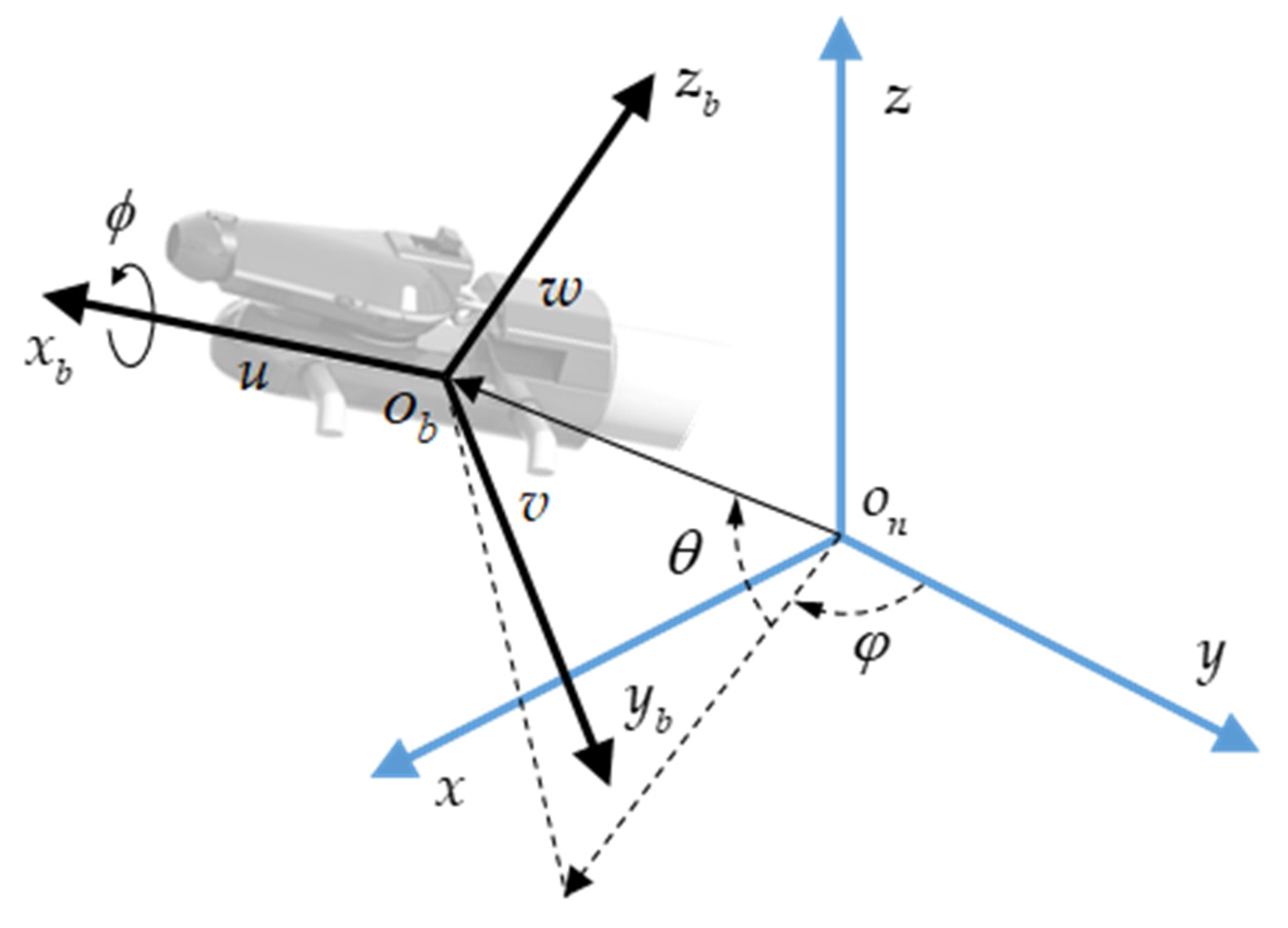
The reference coordinate of the 6-DoF firefighting system is illustrated in Figure 2. The location of the body-fixed frame (b-frame, ) in the earth fixed frame (e-frame, ) is defined by its position (,,) and the three Euler angles (roll, pitch, yaw) (,,). The rotation matrix between the two frames is given as [22]:
The transformation matrix between the body-fixed angular velocity , and the Euler rate is given as [23]:
The schematic drawing of the 6-DoF flying type firefighting system with four water jet actuators is illustrated in Figure 3. The nozzles of the water jet actuators are connected to the sides of the head part at an angle of from the -axis and represent the force of each actuator.
Equations of translational motions and rotational motions of the head part are given as follows:
where is the mass being lifted and it consists of the mass of the head and the mass of water in the water hose connected to the head part. is the density of water, is the cross-sectional area of the water hose, and is a correction factor. Then, Equation (3) can be rewritten as the following:
Supposing that the moment of inertia matrix is diagonal, Equation (4) becomes:
In Equation (5), the force elements are defined as:
and the torque elements in Equation (6) are defined as:
where and are the disturbances induced by the wind, ground effect, and the constraints of the water-supplying hose. Moreover, since the proposed firefighting system is actuated by a water-powered propulsion system, the flow of the fluid should be considered. The derivation of the linear momentum equation of the water-powered system gives the values of the actuator forces as follows [24]:
In Equation (9), the left-hand side is the summation of the actuator forces acting on the system. The first term on the right is the rate of change of the momentum inside the controlled volume. The last term is the net rate of the flow of the linear momentum through the controlled surface. For this system, the controlled volume is defined as the space inside the water system initialing at the water pump inlet and ending at the actuating nozzle outlet. For the simplicity of modeling, the following assumptions are made:
Assumption 1.
The water flows are steady, thus.
Assumption 2.
The flows have uniform velocity profiles, so.
Assumption 3.
The viscosity of the water is neglected in this paper.
Therefore, the actuator forces and torques are respectively derived as follows:
where is the mass flow rate of the water of the nozzle. is the cross-sectional area of the nozzle outlet, and ρ is the density of water. Moreover, let us adopt the following inputs:
corresponds to the total thrust, affects the roll orientation and the translation along the -axis, controls the pitch and the translation along the -axis, and is proportional to the yaw moment. Due to the characteristics of the water-powered system the mass flow rate range is and one can see that the inputs are saturated:
The resulting system model is based on the above-derived equations with the state vector defined as and , and is given by:
where:
Remark 1.
The system consists of two fully actuated channels—vertical and yaw motions—and four underactuated channels. Longitudinal and pitch motions are considered one underactuated system, while lateral and roll motions constitute the other underactuated system with input coupling.
Remark 2.
According to Equations (12) and (13), the input saturations cannot occur simultaneously.
Additionally, let the following assumption be true, which will be useful in the design process of the controller.
Assumption 4.
The elements of the vectorare bounded.
3. Control System Design
In this section, a control system is presented to address the motion control problem of the flying-type firefighting systems in the presence of parametric uncertainties and other disturbances, such as the wind, the ground effect, and constraints of the water-supplying hose. Thus, the SMC is chosen since this control theory is well known for its robustness in facing disturbances and uncertainties, as well as not requiring explicit knowledge of the controlled system. From Equations (14)–(16) the system model can be rewritten as follows:
3.1. Altitude and Position Control
The objective of the altitude and position control is to bring the system to a desired position in the reference coordinate. Let us assume that the rotation matrix is slowly varying and define the position error as the difference between the actual position vector and the desired position vector denoted with a subscript : The desired position vector is assumed to be twice differentiable. Moreover, consider the control error defined as the following:
where and . If the system is properly stabilized, then . Thus, the time-derivative of Equation (20) is given by:
The sliding manifold for the altitude and position control system is chosen as follows:
where the and are the diagonal gain matrices of positive constants. The time-derivative of the sliding manifold yields:
Then, the control law based on the sliding-mode technique is given by:
where is a diagonal matrix and , with is the signum function. Based on Equation (24), the desired value of , and can be calculated from
the following control law:
Remark 3.
andare continuous.
For stability analysis, let us consider the following Lyapunov function candidate:
Then, the time-derivative of this function yields:
where are defined as follows
As a result of Assumption 4, , with , is also bounded. The negative definiteness of is preserved if the following conditions are jointly satisfied:
This implies that the altitude and position control system is stable. Additionally, the sliding variables and are bounded by and , respectively, and the higher the controller gains are, the smaller the size of the bound.
3.2. Attitude Control
The attitude controller is responsible for keeping the 3D orientation of the system at the desired value. To design the control system, let the attitude error be as follows
where is the desired attitude vector of the system and is the actual attitude vector, both are represented by Euler angles. In a similar manner to altitude and position control, the desired attitude vector is also assumed to be twice differentiable. As mentioned in Section 3.1, the desired value and are calculated from the resulting control law of altitude and position control system, as shown in Equation (25). Then, the time-derivative of the attitude error can be calculated as follows:
The sliding manifold for the attitude control system with the diagonal gain matrix as follows,
The time-derivative of Equation (31) is given by:
Accordingly, we propose the sliding mode control law as the following:
where and is a positive definite diagonal gain matrix. Let us introduce the second Lyapunov function for stability analysis of the attitude control system as follows:
Then, along with Equations (33) and (34), the time-derivative of the second Lyapunov function is given as:
Therefore, by choosing such that each of its diagonal elements is greater than the upper bound of the corresponding element of , the stability of the attitude control system is preserved. From Assumption 4, the elements of are bounded.
Figure 4 shows the block diagram of the complete motion control system for the flying-type firefighting system.
3.3. Comparative Control Methods
For a comparative study of the motion control system, PID controllers are designed based on the simplified model of the system. By assuming that the system is properly stabilized ( and ) and the yaw angle is a slow-varying value () and neglecting the uncertain terms from Equation (19), the simplified model is written as follows:
Let us define the following state errors:
Then, the control laws based on the PID control technique is proposed as follows:
where the computed control signals are and the corresponding state errors are . Each of the PID controller gains is tuned by the SIMC rule for the optimal PID control of double integrating processes [25].
where the is the process gain which can be in respect to each . is the time delays of the respective process. The tuning parameters are used as a trade-off between the performance and robustness of the control system.
4. Simulation
To illustrate the usefulness of the flying-type firefighting system model and its motion control system, simulation studies are conducted. Table 1 lists the parameters of the controlled system used in the simulation, based on the pilot model that has been under development in the Marine Cybernetics Laboratory, and is located at the Department of Mechanical System Engineering, Pukyong National University.
By setting the reference trajectory as a three-dimensional spline Equation (42) [26], we can show that the control system proposed is capable of tracking complex desired trajectories from the flying-type firefighting system, even in the presence of disturbances.
The simulation is carried out through two scenarios: tracking the trajectory in (1) the absence of the disturbances and (2) in their presence. The disturbances used in the second simulation scenario are given as [26]:
With this simulation configuration, the controller gains are sufficiently tuned for the best performance possible, and their values are listed in Table 2.
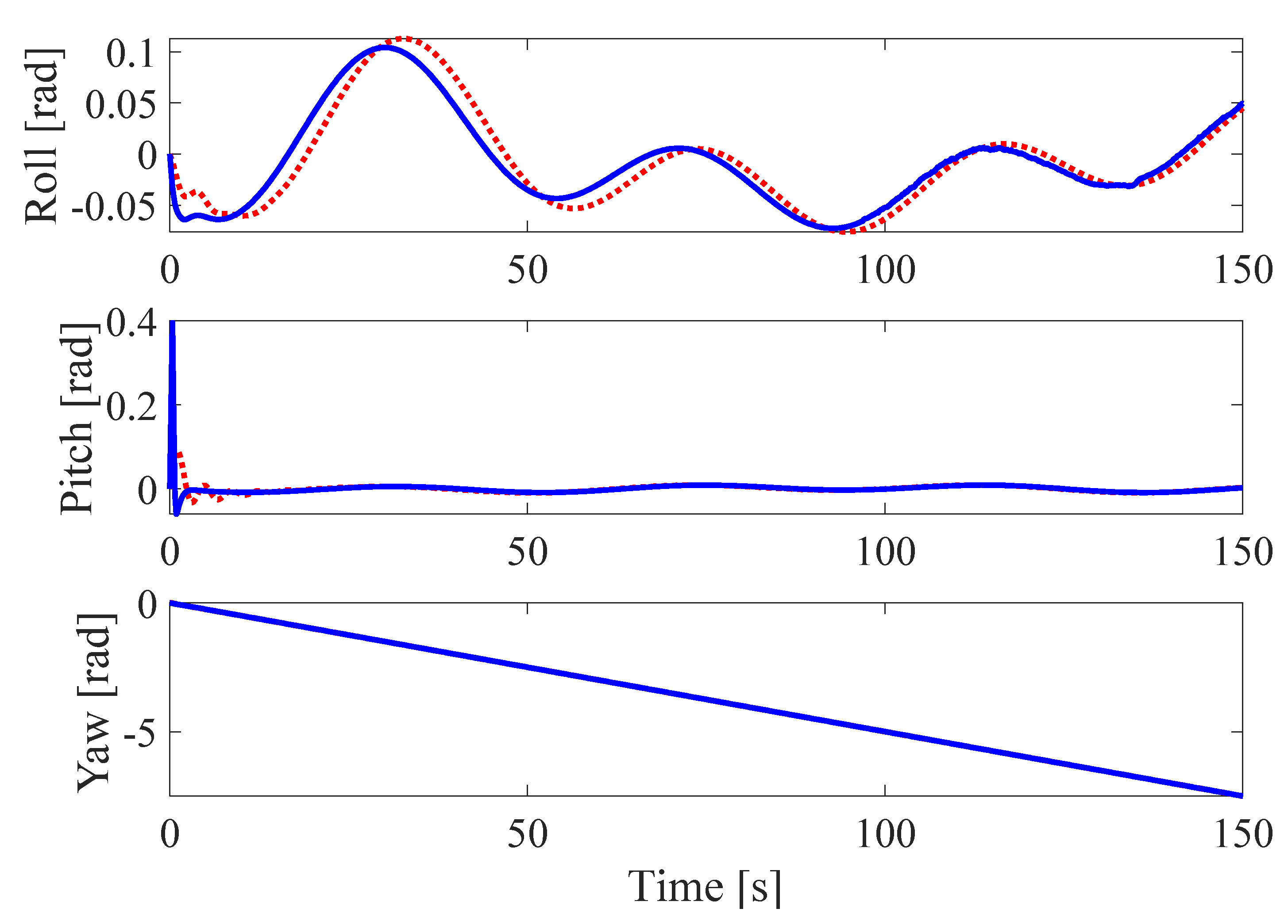
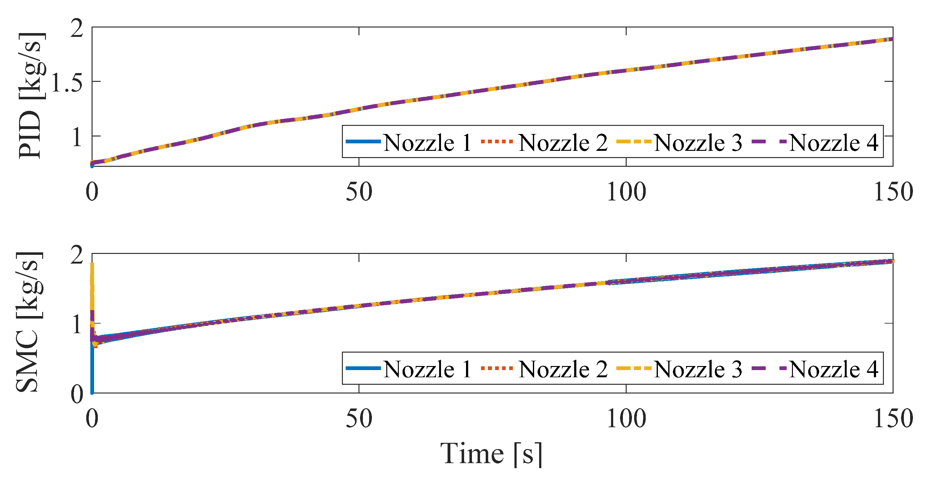
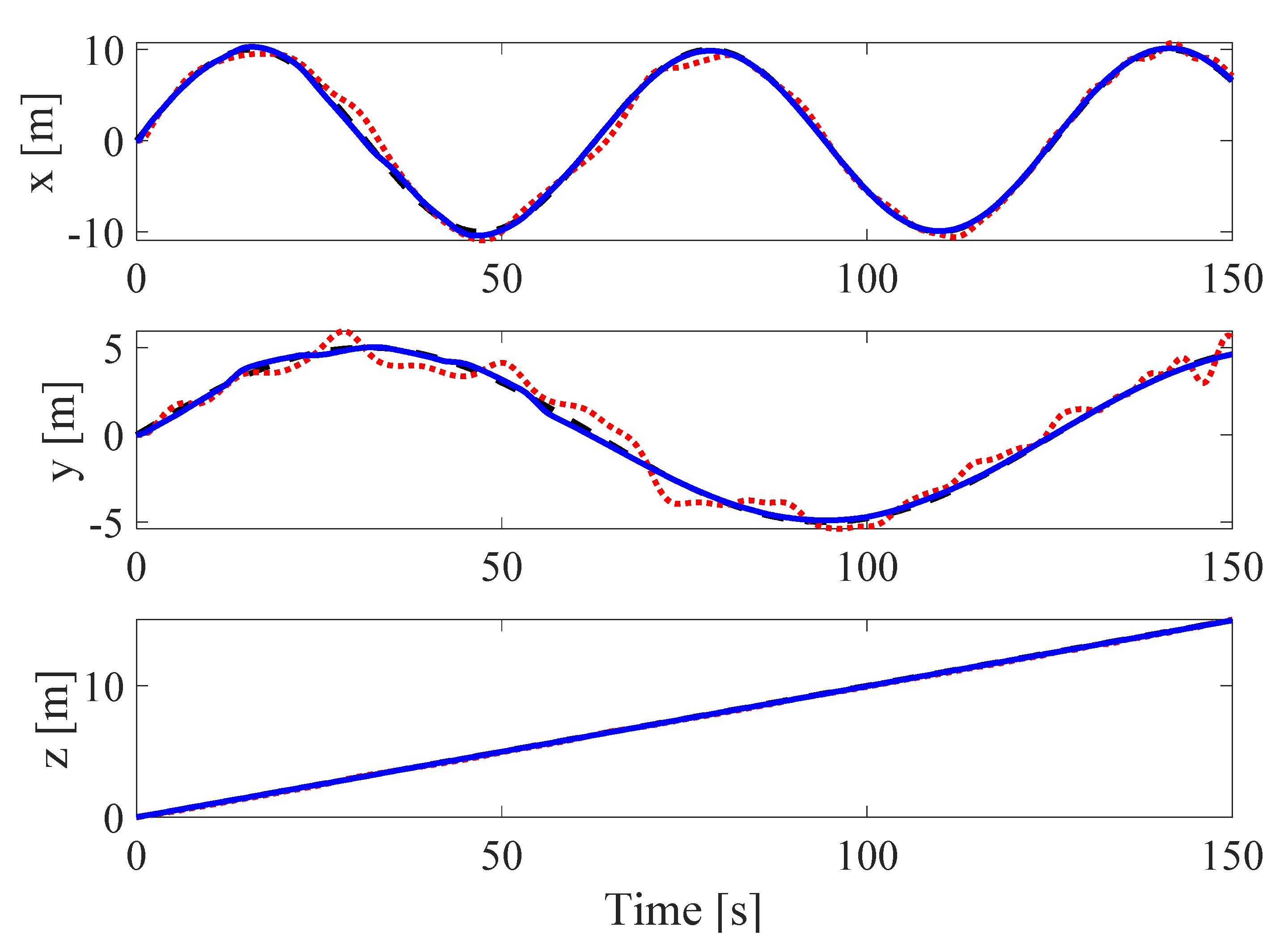
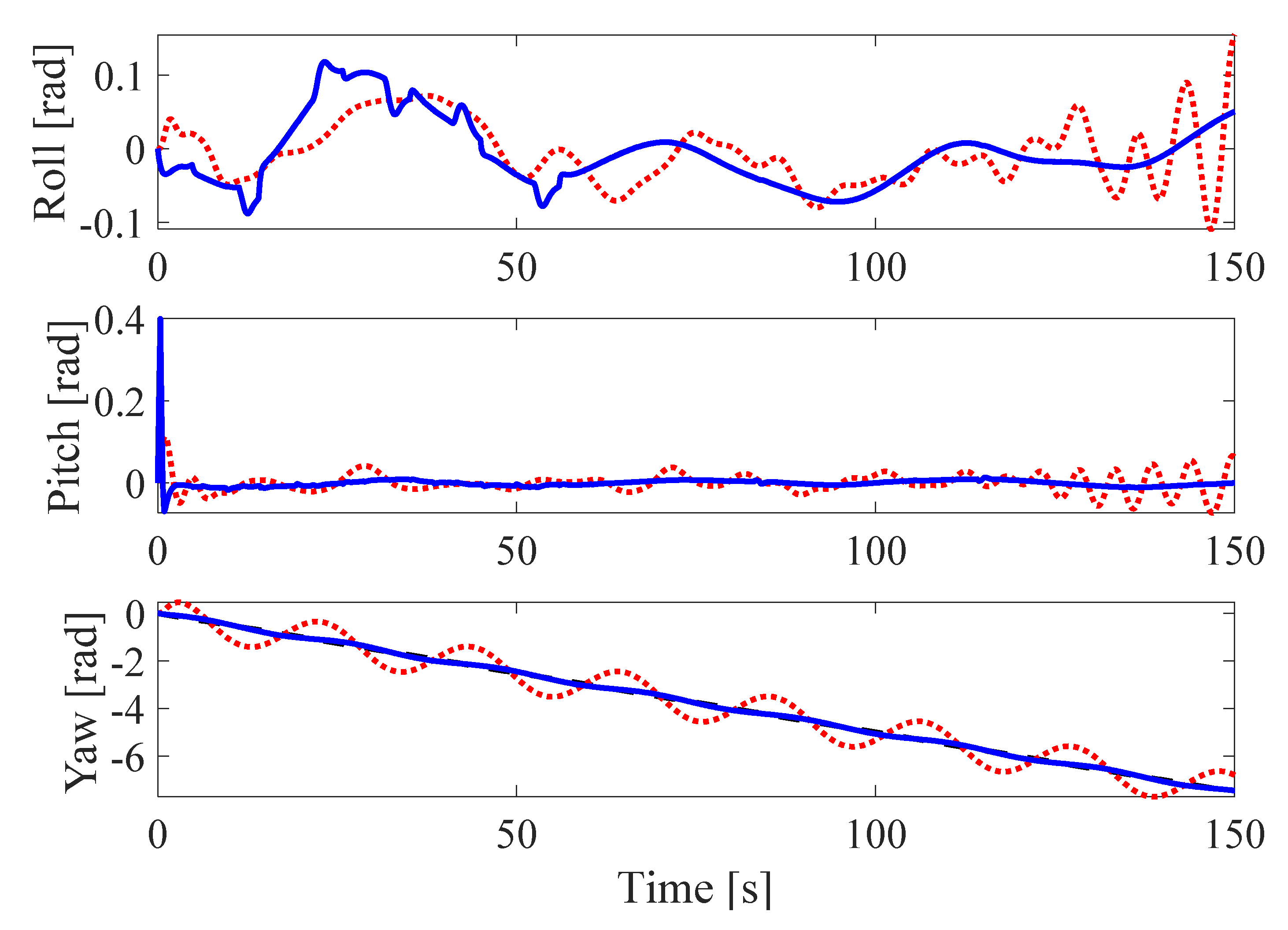
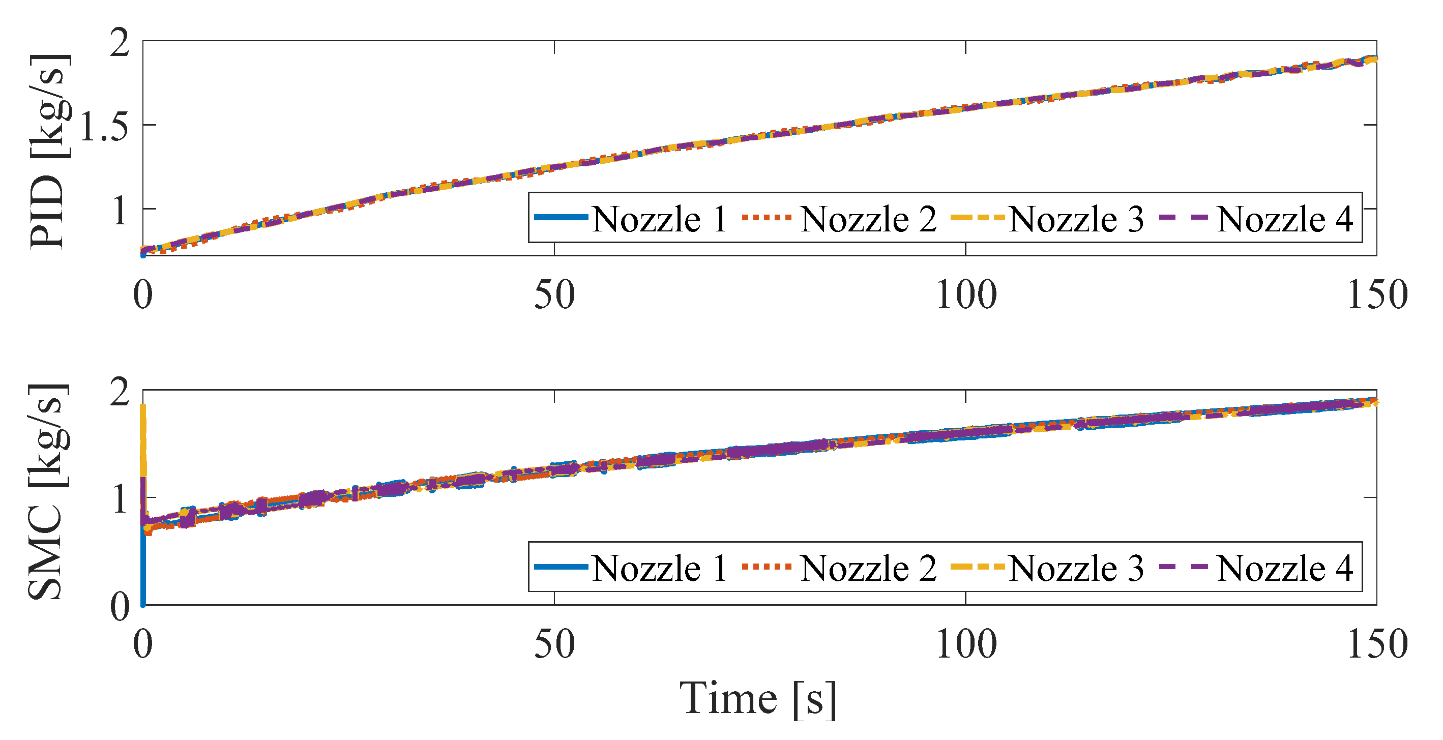
The simulation results of the first scenario are presented in Figure 5,Figure 6,Figure 7 and Figure 8. Figure 5 represents the three-dimensional position of the head part, Figure 6 and Figure 7 represent the position and attitude control response. In Figure 5, Figure 6 and Figure 7, it is clear that both controllers are able to track the reference trajectory well with a good transient response. The errors of the position and yaw angle, in particular, are noticeably small. However, the amplitudes of other state errors using the PID control are significantly larger than with the proposed control system. Figure 8 shows the mass flow rate of each nozzle. The mass flow rate necessary to raise the altitude to 15 m and track the complex trajectory is within 2 kg/s. This is feasible, and these results can be utilized to develop the testbench and pilot model of the proposed system.
As for the second simulation scenario, the disturbances in Equation (43) are applied. The results are shown in Figure 9, Figure 10, Figure 11 and Figure 12. The position and attitude time response is depicted in Figure 9, Figure 10 and Figure 11. Similar to the simulation results without disturbances, both controllers can lead the head part along the reference trajectory. However, residual vibrations appear in the state errors. The mass flow rate shown in Figure 12 is at a similar level to the one depicted in Figure 8 even though the effect of disturbances is considered.
5. Conclusions
In this paper, the authors proposed a new flying-type firefighting system. The proposed system is actuated with a water jet system and controlled for rapid and accurate fire suppression. This paper focused mainly on the dynamic modeling of the novel flying-type firefighting system with water jet actuators and a 6-DoF motion control system design.
The detailed conceptual model of the proposed system that can fly into the flames and suppress the fire was introduced, and the 6-DoF system dynamics were derived with a water-powered propulsion system. The motion control system is designed based on the SMC technique and consists of two components. The first control component is the altitude and position control system, and the second control component is the attitude control, with a part of the desired attitude state calculated with the altitude and position controller. On another note, a PID controller was introduced to carry out a comparative study of the control performance of both control systems.
The simulations were conducted to show the usefulness of the proposed system, the accuracy of the identified parameters, and the efficiency of the motion control system. The simulation tests were conducted in the absence and the presence of disturbances. The SMC showed its superiority over the PID control system in both simulation scenarios. These simulations confirmed that the mass flow rate of the water jet actuator, identified as the control force, is at a feasible level and the parameters used and motion control systems are appropriate. Accordingly, the results of this study can be used in the development of a pilot model for future experimental studies.
Author Contributions
Conceptualization, Y.-B.K.; methodology, Y.-B.K.; software, T.H.; validation, D.-H.L. and Y.-B.K.; formal analysis, T.H., D.-H.L. and Y.-B.K.; investigation, T.H. and Y.-B.K.; resources, D.-H.L. and Y.-B.K.; data curation, D.-H.L. and T.H.; writing—original draft preparation, D.-H.L. and C.S.; writing—review and editing, D.-H.L., C.S. and T.H.; visualization, D.-H.L.; supervision, Y.-B.K.; project administration, Y.-B.K. and D.-H.L.; funding acquisition, Y.-B.K. All authors have read and agreed to the published version of the manuscript.
Funding
Following are results of a study on the “Leaders in Industry-university Cooperation +” Project, supported by the Ministry of Education and National Research Foundation of Korea, and BK21 FOUR (Smart Robot Convergence and Application Education Research Center) project by the National Research Foundation of Korea.
Institutional Review Board Statement
Not applicable.
Informed Consent Statement
Not applicable.
Data Availability Statement
Not applicable.
Conflicts of Interest
The authors declare no conflict of interest.
References
- Liljeback, P.; Stavdahl, O.; Beitnes, A. SnakeFighter—Development of a Water Hydraulic Fire Fighting Snake Robot. In Proceedings of the 2006 9th International Conference on Control, Automation, Robotics and Vision, Singapore, 5–8 December 2006; pp. 1–6. [Google Scholar] [CrossRef]
- Kim, J.-H.; Jo, S.; Lattimer, B.Y. Feature Selection for Intelligent Firefighting Robot Classification of Fire, Smoke, and Thermal Reflections Using Thermal Infrared Images. J. Sens. 2016, 2016, 1–13. [Google Scholar] [CrossRef] [Green Version]
- Bogue, R. The role of robots in firefighting. Ind. Robot Int. J. Robot. Res. Appl. 2021, 48, 174–178. [Google Scholar] [CrossRef]
- Shark Robotics Colossus. Available online: https://www.shark-robotics.com/ (accessed on 16 October 2021).
- Howe & Howe Thermite. Available online: https://www.howeandhowe.com/civil/thermite (accessed on 16 October 2021).
- Spurny, V.; Pritzl, V.; Walter, V.; Petrlik, M.; Baca, T.; Stepan, P.; Zaitlik, D.; Saska, M. Autonomous Firefighting Inside Buildings by an Unmanned Aerial Vehicle. IEEE Access 2021, 9, 15872–15890. [Google Scholar] [CrossRef]
- Saikin, D.A.; Baca, T.; Gurtner, M.; Saska, M. Wildfire Fighting by Unmanned Aerial System Exploiting Its Time-Varying Mass. IEEE Robot. Autom. Lett. 2020, 5, 2674–2681. [Google Scholar] [CrossRef]
- Pham, H.X.; La, H.M.; Feil-Seifer, D.; Deans, M.C. A Distributed Control Framework of Multiple Unmanned Aerial Vehicles for Dynamic Wildfire Tracking. IEEE Trans. Syst. Man Cybern. Syst. 2020, 50, 1537–1548. [Google Scholar] [CrossRef] [Green Version]
- Ausonio, E.; Bagnerini, P.; Ghio, M. Drone Swarms in Fire Suppression Activities: A Conceptual Framework. Drones 2021, 5, 17. [Google Scholar] [CrossRef]
- Ghamry, K.A.; Kamel, M.A.; Zhang, Y. Multiple UAVs in forest fire fighting mission using particle swarm optimization. In Proceedings of the 2017 International Conference on Unmanned Aircraft Systems (ICUAS), Miami, FL, USA, 13–16 June 2017; pp. 1404–1409. [Google Scholar] [CrossRef]
- Zapata, F. Maneuvering and Stability Control System for Jet-Pack. US Patent 2014/0103165, 17 April 2014. [Google Scholar]
- Li, R. Personal Propulsion Device 2007. US Patent 7,900,867, 8 March 2011. [Google Scholar]
- Naidoo, J.E. Modelling, Design and Analysis of a Water Jetpack Powered by an Autonomous Underwater Vehicle (AUV) System. Master’s Thesis, University of KwaZulu-Natal, Pietermaritzburg, South Africa, 2017. [Google Scholar]
- Robinson, B. Water Propelled Flying Board. US Patent 9,145,206, 30 October 2015. [Google Scholar]
- Li, R. Personal Propulsion Devices with Improved Balance. Spain Patent 2 659 042, 8 November 2014. [Google Scholar]
- Liu, X.; Zhou, H. Unmanned Water-Powered Aerial Vehicles: Theory and Experiments. IEEE Access 2019, 7, 15349–15356. [Google Scholar] [CrossRef]
- Jetovator. Available online: https://www.jetovator.com/ (accessed on 16 October 2021).
- Ando, H.; Ambe, Y.; Ishii, A.; Konyo, M.; Tadakuma, K.; Maruyama, S.; Tadokoro, S. Aerial Hose Type Robot by Water Jet for Fire Fighting. IEEE Robot. Autom. Lett. 2018, 3, 1128–1135. [Google Scholar] [CrossRef]
- Yamaguchi, T.; Ambe, Y.; Ando, H.; Konyo, M.; Tadakuma, K.; Maruyama, S.; Tadokoro, S. A Mechanical Approach to Suppress the Oscillation of a Long Continuum Robot Flying with Water Jets. IEEE Robot. Autom. Lett. 2019, 4, 4346–4353. [Google Scholar] [CrossRef]
- Yamauchi, Y.; Ambe, Y.; Konyo, M.; Tadakuma, K.; Tadokoro, S. Passive Orientation Control of Nozzle Unit with Multiple Water Jets to Expand the Net Force Direction Range for Aerial Hose-Type Robots. IEEE Robot. Autom. Lett. 2021, 6, 5634–5641. [Google Scholar] [CrossRef]
- Thorncroft, G.E.; Ridgely, J.R.; Pascual, C.C. Hydrodynamics and thrust characteristics of a water-propelled rocket. Int. J. Mech. Eng. Educ. 2009, 37, 241–261. [Google Scholar] [CrossRef]
- Niku, S.B. Introduction to Robotics: Analysis, Control, Applications; John Wiley & Sons: Hoboken, NJ, USA, 2020; ISBN 1119527627. [Google Scholar]
- Peraire, J.; Widnall, S. Lecture L29-3D Rigid Body Dynamics. Dynamics 2009. Fall, Version 2.0. Available online: http://ckw.phys.ncku.edu.tw/public/pub/Notes/PathIntegral/Kleinert/01._Fundamentals/junk/MIT16_07F09_Lec29.pdf (accessed on 4 October 2021).
- Munson, B.R.; Young, D.F.; Okiishi, T.H. Fundamentals of fluid mechanics. Fundam. Fluid Mech. 1994. [Google Scholar] [CrossRef]
- Grimholt, C.; Skogestad, S. Optimal PID control of double integrating processes. IFAC-PapersOnLine 2016, 49, 127–132. [Google Scholar] [CrossRef]
- Xuan-Mung, N.; Hong, S.K. Robust Backstepping Trajectory Tracking Control of a Quadrotor with Input Saturation via Extended State Observer. Appl. Sci. 2019, 9, 5184. [Google Scholar] [CrossRef] [Green Version]
Figure 1.
Conceptual drawing of flying-type firefighting system with the water jet actuator.
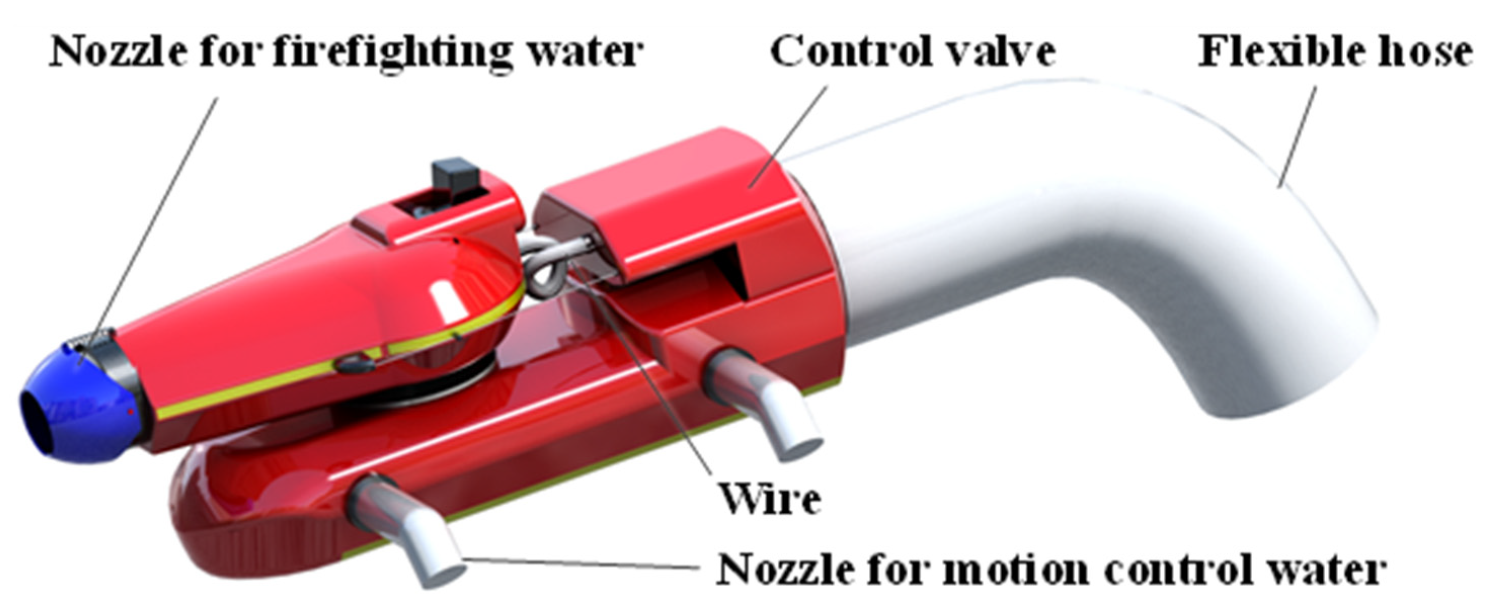
Figure 2.
Reference-coordinated description of flying type firefighting system with water jet actuator.
Figure 2.
Reference-coordinated description of flying type firefighting system with water jet actuator.

Figure 3.
Head part schematic drawing of the proposed system.
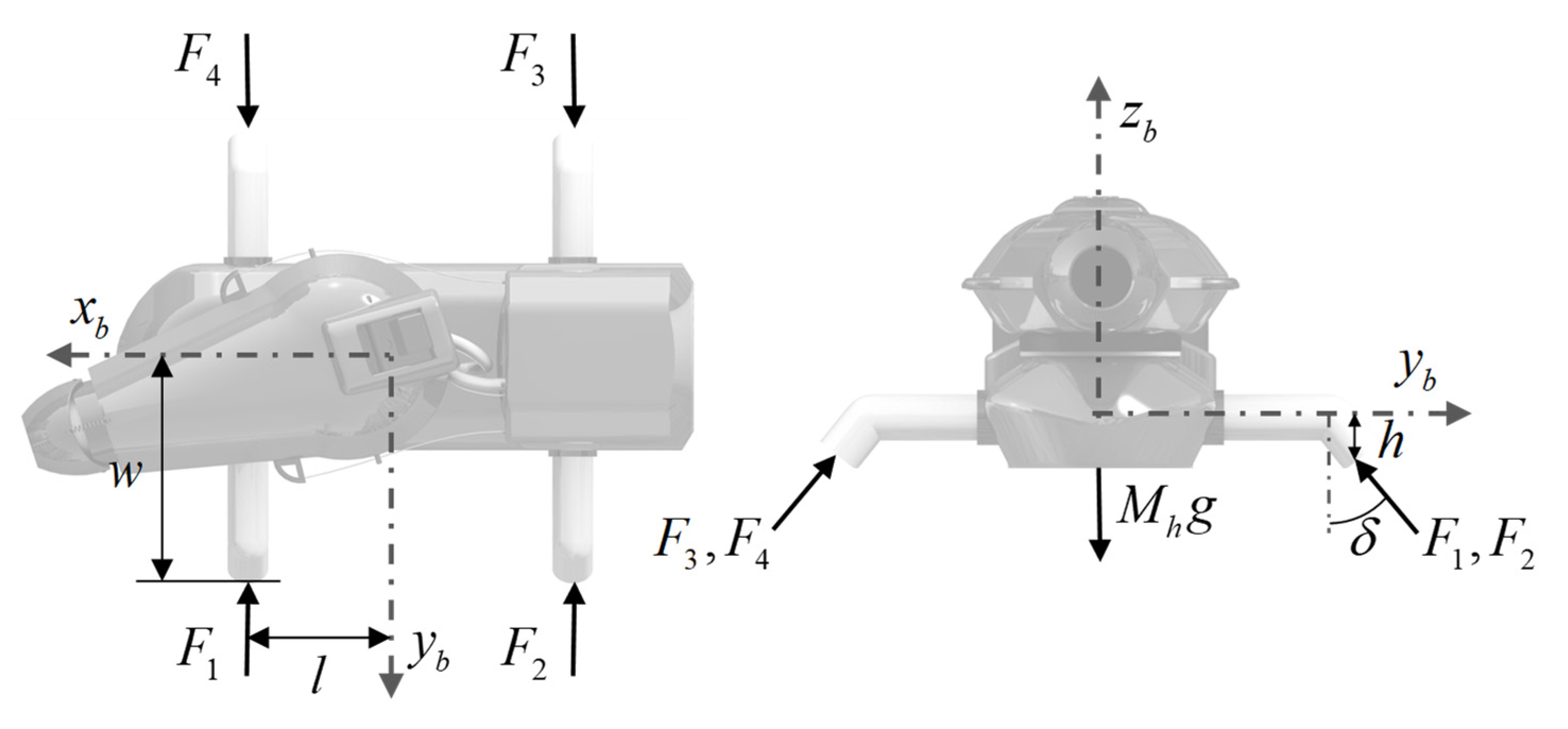
Figure 4.
Block diagram of the motion control system for the flying-type firefighting system with water jet actuators.
Figure 4.
Block diagram of the motion control system for the flying-type firefighting system with water jet actuators.
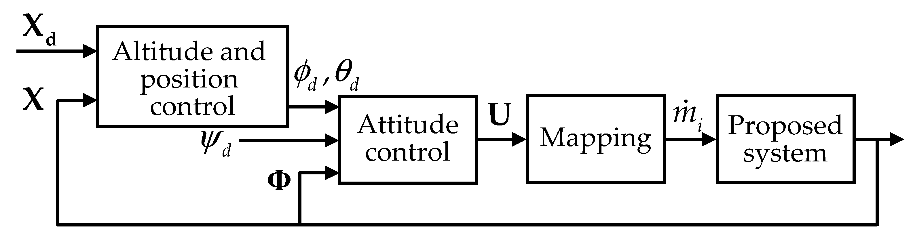
Figure 5.
Trajectory tracking performance of the flying-type firefighting system in three-dimensional view.
Figure 5.
Trajectory tracking performance of the flying-type firefighting system in three-dimensional view.

Figure 6.
Position control response of two motion control systems. The red dotted line is PID control; the solid blue line is SMC; the black dashed reference trajectory line along the -direction is .
Figure 6.
Position control response of two motion control systems. The red dotted line is PID control; the solid blue line is SMC; the black dashed reference trajectory line along the -direction is .
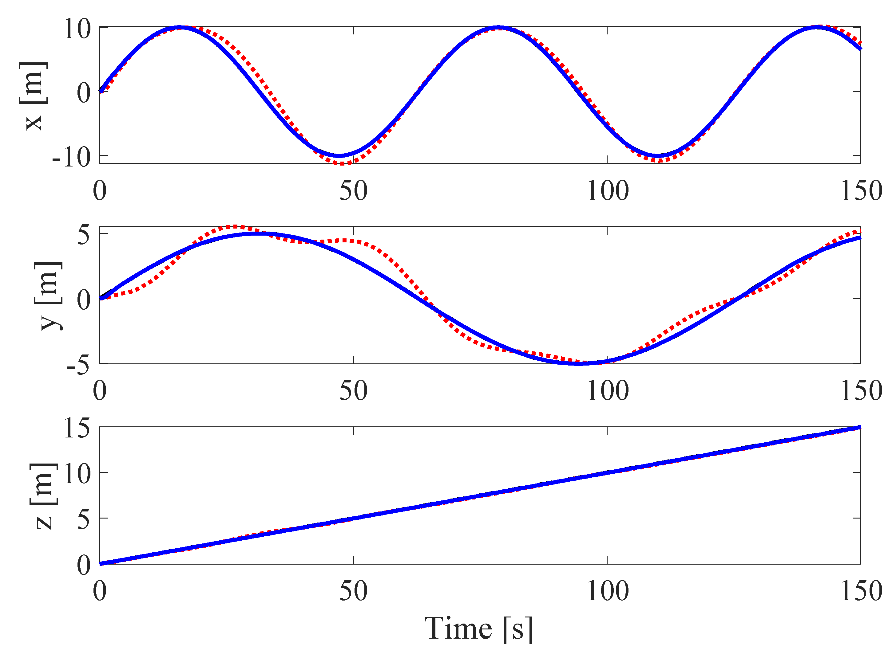
Figure 7.
Attitude control response of two motion control systems. The red dotted line is PID control; the solid blue line is SMC; the reference trajectory of the yaw motion is .
Figure 7.
Attitude control response of two motion control systems. The red dotted line is PID control; the solid blue line is SMC; the reference trajectory of the yaw motion is .

Figure 8.
The mass flow rate of each nozzle.

Figure 9.
Trajectory tracking performance of the flying type firefighting system with disturbances in three-dimensional view.
Figure 9.
Trajectory tracking performance of the flying type firefighting system with disturbances in three-dimensional view.
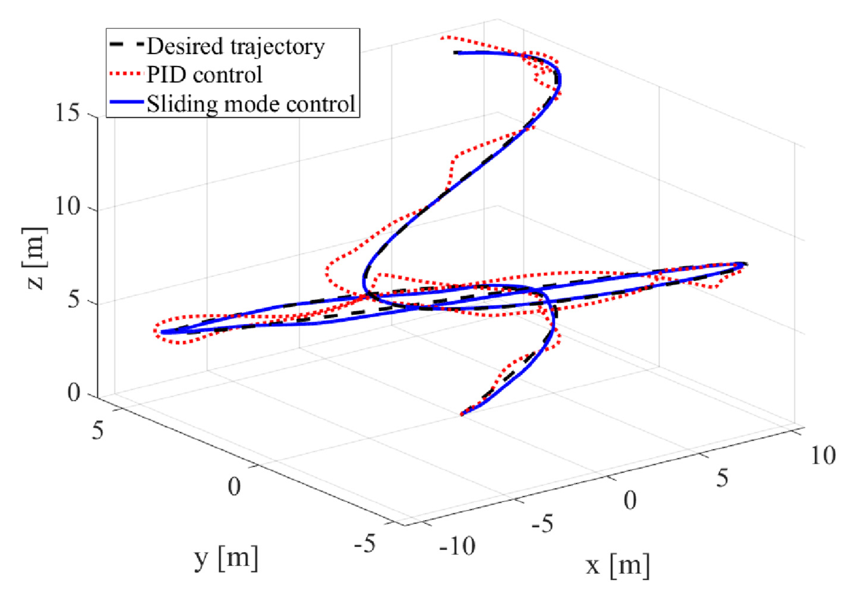
Figure 10.
Position control response of two motion control systems in the presence of disturbances. The red dotted line is PID control; the solid blue line is SMC; the black dashed reference trajectory line along the -direction is .
Figure 10.
Position control response of two motion control systems in the presence of disturbances. The red dotted line is PID control; the solid blue line is SMC; the black dashed reference trajectory line along the -direction is .

Figure 11.
Position control response of two motion control systems in the presence of disturbances. The red dotted line is PID control; the solid blue line is SMC; the reference trajectory of the yaw motion is .
Figure 11.
Position control response of two motion control systems in the presence of disturbances. The red dotted line is PID control; the solid blue line is SMC; the reference trajectory of the yaw motion is .

Figure 12.
The mass flow rate of each nozzle.


Table 1.
Parameters of the flying-type firefighting system used in the simulation study.
| Parameter | Description | Value | Unit |
|---|---|---|---|
| Mass of the head part | 2 | kg | |
| Moment of inertia matrix | kg·m2 | ||
| Configuration parameters of the nozzle | 0.5, 0.4, 0.1 | m | |
| Nozzle angle to the | 45 | deg | |
| The cross-sectional area of the water hose | 4.9110−4 | m2 | |
| The cross-sectional area of the nozzle | 7.8510−5 | m2 | |
| Correction factor | 1.5 | - |
Table 2.
Controller gains used in the simulation.
| Gains | Values | Gains | |
|---|---|---|---|
Publisher’s Note: MDPI stays neutral with regard to jurisdictional claims in published maps and institutional affiliations. |
© 2021 by the authors. Licensee MDPI, Basel, Switzerland. This article is an open access article distributed under the terms and conditions of the Creative Commons Attribution (CC BY) license (https://creativecommons.org/licenses/by/4.0/).
Share and Cite
MDPI and ACS Style
Lee, D.-H.; Huynh, T.; Kim, Y.-B.; Soumayya, C. Motion Control System Design for a Flying-Type Firefighting System with Water Jet Actuators. Actuators 2021, 10, 275. https://doi.org/10.3390/act10100275
AMA Style
Lee D-H, Huynh T, Kim Y-B, Soumayya C. Motion Control System Design for a Flying-Type Firefighting System with Water Jet Actuators. Actuators. 2021; 10(10):275. https://doi.org/10.3390/act10100275
Chicago/Turabian StyleLee, Dong-Hun, Thinh Huynh, Young-Bok Kim, and Chakir Soumayya. 2021. "Motion Control System Design for a Flying-Type Firefighting System with Water Jet Actuators" Actuators 10, no. 10: 275. https://doi.org/10.3390/act10100275
Note that from the first issue of 2016, this journal uses article numbers instead of page numbers. See further details here.