Article

An Actuator Concept for Adaptive Concrete Columns

1
Institute for Lightweight Structures and Conceptual Design (ILEK), University of Stuttgart, Pfaffenwaldring 14, 70569 Stuttgart, Germany
2
Institute for Engineering Design and Industrial Design (IKTD), University of Stuttgart Pfaffenwaldring 9, 70569 Stuttgart, Germany
*
Author to whom correspondence should be addressed.
Actuators 2021, 10(10), 273; https://doi.org/10.3390/act10100273
Submission received: 18 September 2021 / Revised: 13 October 2021 / Accepted: 14 October 2021 / Published: 16 October 2021

Abstract

:
The building industry accounts for half of the global resource consumption and roughly one third of global CO2 emissions. Global population growth and increasing resource scarcities require engineers and architects to build for more people with less material and emissions. One promising solution are adaptive load-bearing structures. Here, the load-bearing structure is equipped with actuators, sensors, and a control unit which allows the structure to adapt to different load cases, resulting in substantial material savings. While the first prototypes use industry standard actuators to manipulate deformations and stress states, it is essential to develop actuator concepts which fit the specific requirements of civil engineering structures. This paper introduces new concepts for linear actuators, developed within the Collaborative Research Centre (SFB) 1244 Adaptive Skins and Structures for the Built Environment of Tomorrow, which can be used as adaptive concrete columns. The concept of an actuator which actuates a concrete column by external compression through hydraulic pressure is discussed in further detail. This concept allows for controlled axial extension while also increasing the compressive strength of the concrete column.

1. Introduction

1.1. Adaptive Engineering Structures

By volume, the most used material worldwide (and which is especially important in the construction of civil engineering structures) are cementitious materials, such as (reinforced) concrete [1]. The use of concrete as a building material is so widespread that the production of cement, the first main ingredient, causes up to 10% of the total anthropogenic CO2 emissions [2], while resource deposits for sand, the second main ingredient, are running scarce [3]. Overall, the building industry accounts for 50% of the global resource consumption and for more than 38% of global CO2 emissions [4,5,6]. In combination with the still increasing world population and accelerating climate change new material and emission efficient building technologies need to be developed [7]. While the reuse and recycling of materials is an important first step that should become self-evident, a new approach that goes beyond todays practice is the development of adaptive structures, also defined as ultra-lightweight structures [5]. Integrating actuators and sensors into the load-bearing structure and establishing a control algorithm allows the structure to manipulate its load-bearing behavior to adapt optimally to the given situation. This can lead to substantial material and emission savings [8,9,10,11], as explained in the following. First, the load-bearing structure has to withstand any loading that may occur (with a certain probability) during its use phase. In practice, however, this means that the structural elements are oversized for most regularly occurring load cases [12,13]. Here, actuators can be used to homogenize stresses and strains [14,15] or generate shape changes to establish a more efficient load transfer, when the structure is loaded by rare loads of often higher intensity. The structural members can then be designed for the lower, more regularly occurring load cases. [16,17]. Secondly, certain serviceability criteria such as deformations limits have to be met to assure user comfort and to prevent, for example, partition walls or façade elements from cracking. These serviceability limits also often govern the design, such that the structural elements are again oversized for the stresses acting in those elements. Through actuation it is possible to induce counter deformations which reduce or even compensate the deformations allowing the structural member to be sized according to the stresses [18,19,20]. Which of these actuation strategies yields the most material and emission savings depends highly on the type of building or structure that is to be actuated. A combination of both strategies is also possible.
Most prototypes use linear actuators to manipulate the structural behavior, for example, hydraulic [16,21], pneumatic [22] or electromechanical actuators [13]. While these industry standard actuators present a solution that is economical and easy to implement, it may be not the most efficient. The reason for this is that the demands on actuators in civil engineering structures vary from other industrial use cases. In particular, actuators (may) need to withstand extremely high static forces (dead load), but need to actuate only small strokes.
Therefore, new actuation and actuator concepts are being developed to address other performance requirements. In [20] actuators were integrated into the component cross-section for the first time using the example of a beam. In this use case only small strokes (<0.5 mm) and moderate forces (<50 kN) are required to compensate deformations caused by external loads. Therefore, special pressure chambers were developed which can be integrated into the cross-section in an eccentric position relative to the neutral axis. By integrating several of these fluidic actuators, it is possible to react optimally to a wide range of load cases and to fully compensate for the deflection. In addition to fluidic actuators, other actuator types are conceivable. In [23] it is shown that expansion material actuators can also be used. However, these are only suitable for quasi-static applications.
This paper presents and briefly discusses four new concepts for adaptive concrete columns. These adaptive columns can be employed as linear actuators, meaning it is possible to realize a vertical extension. The general introduction is followed by a more detailed presentation of one of the four actuation concepts, which can also increase the compressive strength of its central concrete column through actuation, by externally compressing the concrete column in the lateral direction. This effect can also be exploited in passive composite concrete columns [24,25,26,27,28] to strengthen the concrete column through external compression. Other commercial products are designed for subsequent strengthening of columns to extend the use phase of the respective building. However, the increase in compressive strength in these approaches is either limited to the relative deformations (e.g., ν S t e e l / ν C o n c r e t e 0.3 / 0.2 ) or to the (post) tensioning force with which the enveloping materials are applied.

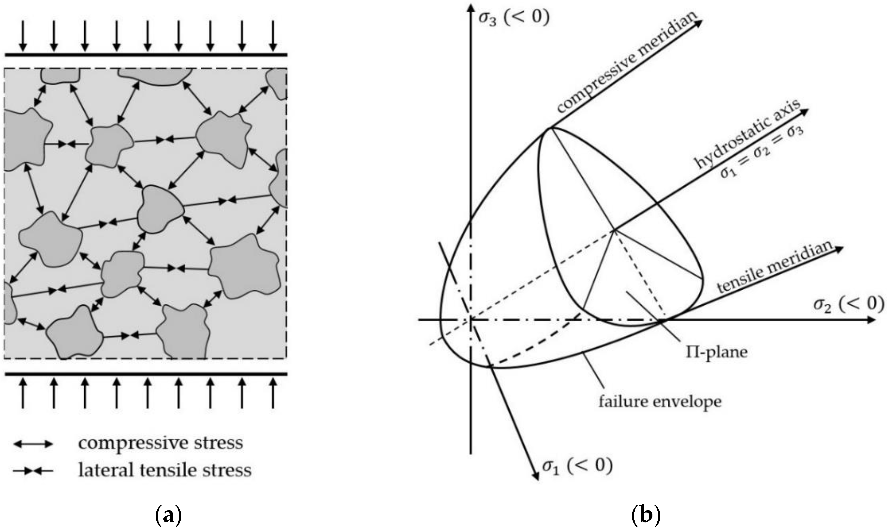
1.2. Material Properties of Concrete

Concrete generally has a high compressive strength and low or even negligible tensile strength (Table 1). Its mechanical behavior can be described as a two-phase system: aggregate and cement matrix (Figure 1a). For normal-strength concrete ( f c m 50   MPa ) the strength and stiffness of the aggregates is higher than that of the cement matrix. This means that evenly loaded concrete in compression does not result in evenly distributed compressive stresses. The compressive stresses are primarily carried by the inhomogeneously distributed aggregates, resulting in tensile stresses perpendicular to the compressive stresses (Figure 1a). It is these transverse tensile stresses that lead to failure. They determine the axial compressive strength of concrete. If these lateral tensile stresses are being compensated through lateral compressive stress, the overall (multiaxial) compressive strength increases [12,29,30].
The achievable increase in compressive strength is highly dependent on the relative state of the multiaxial loading. Different fracture criteria have been developed to describe the failure envelope depicted in Figure 1b, where σ 1 σ 2 σ 3 [29]. The differences in the fracture criteria are primarily in their underlying assumptions and therefore precision in modeling concrete of different strengths and stress states. The formulations are based on various concrete properties such as the uniaxial strength. These parameters can generally be calibrated through experiments; however these experiments can be relatively elaborate, depending on the parameter [30]. Generalized criteria, such as the one proposed in [31] can therefore be preferable. Every multiaxial state of stresses encompassed by the failure envelope does not result in failure. The failure envelope can be characterized by the hydrostatic axis ( σ 1 = σ 2 = σ 3 ), the compressive meridian ( σ 1 = σ 2 > σ 3 ) and the tensile meridian ( σ 1 > σ 2 = σ 3 ). For compression only loading, the envelope is opening up along the hydrostatic axis, meaning the higher the multiaxial compressive loading, the higher the multiaxial compressive strength. However, tensile stresses further reduce the multiaxial strength, leading to earlier failure. For rotationally symmetric compressive stress states, i.e., cylindrical columns, the multiaxial compressive strength can be estimated as:
f c , 3 = f c + 4 σ ,
with f c , 3 being the multiaxial compressive strength, f c being the uniaxial compressive strength and σ being the lateral, rotationally symmetric compression [32].

2. Concepts for Adaptive Concrete Columns
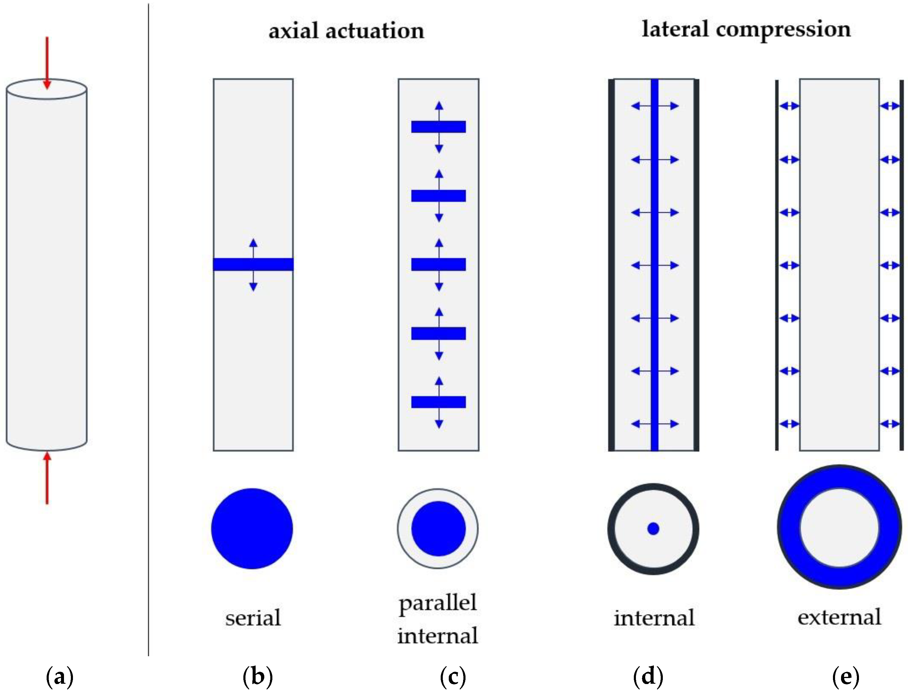
2.1. Basic Concepts

Figure 2 shows the schematic application of the adaptive concrete columns under an external compressive (blue) or tensile (red) axial force F and the resulting stresses. The field of adaptive civil engineering structures distinguishes between two main categories of linear actuation concepts due to the differences in mechanical behavior and adaptation potentials [33]: actuation in series and parallel actuation [34]. One major difference, which is also relevant for the design of actuators, is the difference in the loading of the actuator. Installation in series means that the actuator itself also has to carry permanent loads acting on the element, while the parallel actuator only has to withstand the actuation forces during actuation [21,35]. Furthermore, for constrained systems such in Figure 2, a reduction of deformations through actuation in series results in additional stresses in the actuator element. This means that the adaptive stress state determines the dimensions of the actuator. In the case of parallel deformation actuation, however, the stresses from the external loads and actuation are of inverted sign, resulting in a reduction or even compensation of stresses in the actuated element.
Figure 3 shows four concepts (b–e) for adaptive concrete columns with a cylindrical concrete base (A). In their current form, these concepts allow only for actuation in extension. Concepts (B) and (C) function through axial expansion of horizontally placed actuators and concepts (D) and (E) through lateral compression of vertical actuators. In concept (B), an actuator element is placed along the concrete column, which separates the column into two parts, cutting through the whole cross-section (actuation in series). While this actuator can extend or retract freely, it has to withstand all forces acting on the column, which can be up to several Meganewton (e.g., columns in high-rises) [21]. Concept (C) places the actuators inside the cross-section of concrete column, leaving a remaining concrete section to partially carry the axial loading. However, this constrains the movement of the actuators in the axial direction, leading to constraint stresses which are short-circuited along the remaining concrete section [20] (parallel character, cf. [21]). Concepts (D) and (E), therefore, keep the concrete section largely undisturbed and use the transverse strain ( ν 0.2 ) to create actuator travel, by compressing the concrete section laterally to generate an axial extension. The horizontal compression combined with axial compression from external forces creates a multiaxial compressive state, thus increasing the compressive strength of the concrete. This actuator concept, which globally acts as a serial actuator (Figure 2), therefore counteracts the disadvantage of superposed compressive stresses in the adaptive state through a greater compressive strength in the adaptive state. However, it must be ensured that only compressive stresses prevail in the concrete section. In concept (D) an internally placed actuator is pressing the concrete section outwards against a confining tube. To avoid short-circuiting of the induced compressive stresses which would result in tensile stresses, the actuator cannot be surrounded by concrete (parallel character), but has to separate the concrete section into individual parts (serial character). In concept (E) the potential of short-circuiting is avoided by externally compressing the concrete section. This guarantees homogeneous compressive stresses equal to the externally applied compression. Concepts (D) and (E) therefore have reduced capabilities in actuator travel by the factor of the Poisson ration with respect to concepts (B) and (C), in exchange for increasing the compressive strength of concrete.
Typical requirements for the actuation of structural elements are high forces to be generated with small strokes. To avoid influencing the surrounding structure or architecture, an unobtrusive integration (concepts (B–D)) or connection (concept (E)) of the actuators must be ensured. This means that the adaptive column should correspond as closely as possible to the geometry of the original design. Furthermore, it must be ensured that the weak point created by integrating the actuators into the structure is minimized (especially for concepts (B–D)). Therefore, the aim should be to achieve the highest possible power density. Hydraulic actuators can generate large forces and are characterized by a high-power density [36,37]. Thus, their usage seems appropriate for the implementation of the concepts, though their ecological assessment is not optimal. Starting from a central pressure source, e.g., a hydraulic power unit, the pressurized fluid can be supplied to the required sections in a targeted manner. Distribution of the fluid to individual pressure chambers, e.g., for concept (C), is also possible with little effort. By means of valves, the pressure can be adjusted separately, e.g., for optimizing the stress distribution within the column. In the concepts (D) and (E) shown above, the force is applied over large areas of the column surface. By applying hydraulic pressure, a uniform force distribution over the entire surface is ensured. The pressure can be monitored using pressure sensors. Standard components can be used for pressure generation, hydraulic fluid management and pressure monitoring. Therefore, the investigation can be placed on the actual adaptation of the column.

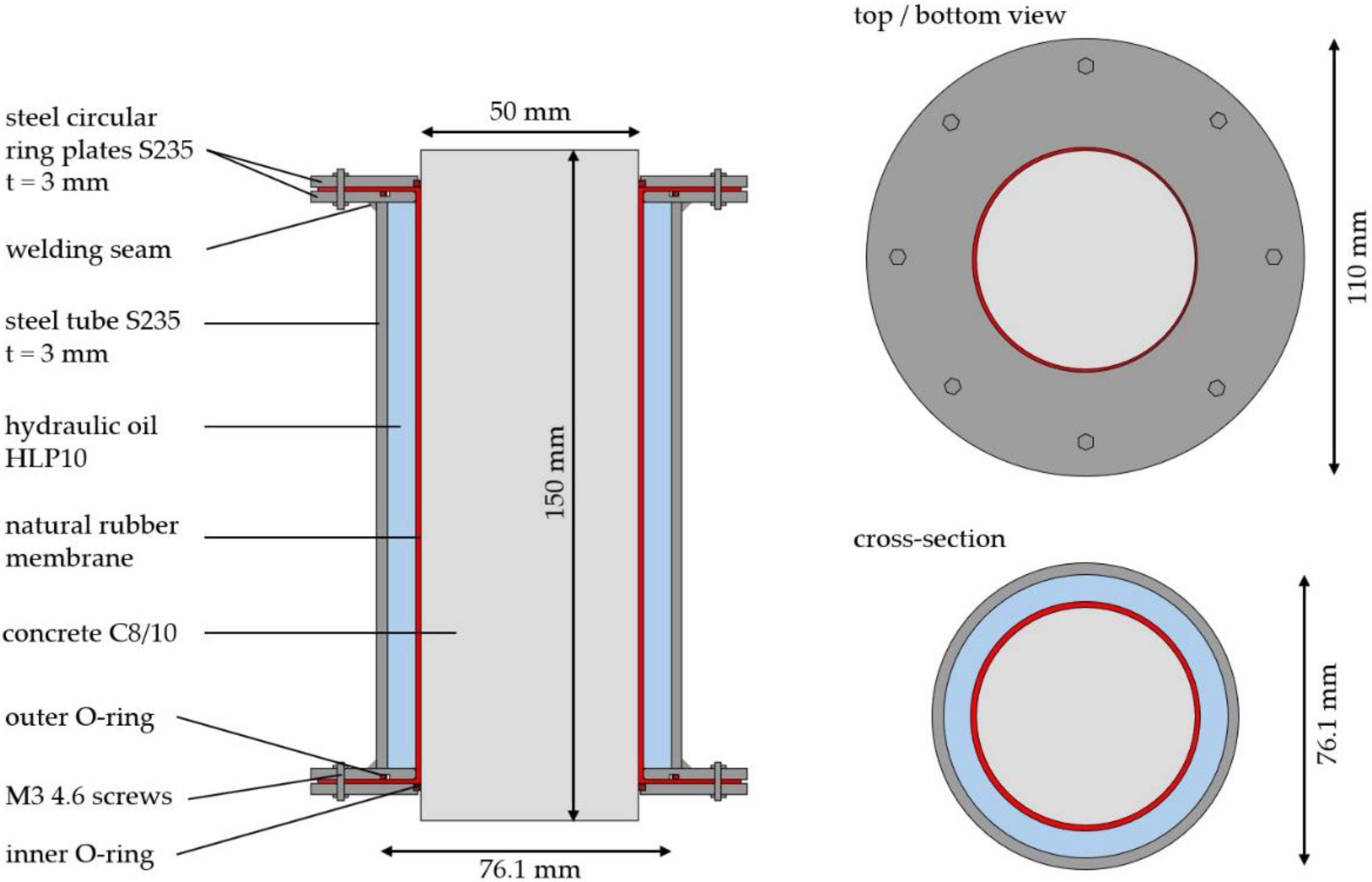
2.2. Prototype of an Externally Compressed Adaptive Concrete Column

Based on the advantages discussed in Section 2.1, the actuation concept of external lateral compression (concept (E)) is chosen for further analysis. To validate the concept of the adaptive concrete column, a small-scale prototype was built and experimentally tested. Underlying the design are four premises: first, the design should account for a concrete-connection on either end of the column, i.e., the column has to extend from the actuator. Second, the actuator should be excluded from the axial load transfer to clearly identify the potential of lateral compression. The third and fourth premises address and optimize the recyclability and sustainability for the chosen hydraulic actuation: the concrete has to be isolated from the hydraulic oil so as to prevent any contamination of the concrete and keep both materials reusable or recyclable; moreover, the design should refrain from permanent fixtures (e.g., adhesives or sealing foam) so that that the individual parts can easily be taken apart, cleaned and reused or recycled. Figure 4 shows the final design for the prototype.
The overall dimensions are a compromise of the early development stage as well as manufacturability and testability with standard lab equipment and are based on typical measurements of concrete test specimen of triaxial tests performed to identify the envelope in Figure 1b. These have commonly a diameter/height (d/h) of 100/200 mm; however [38] and [39] also used specimen with a diameter of 50 mm. Further measures were taken to ensure similar behavior of the scaled down specimen to real-scale concrete columns: the diameter of the largest aggregate d g is limited to less than one third of the diameter of the specimen ( d g = 8   mm < 16.7   mm ) and the volume V of the specimen is set as follows [40]:
V 4 d g 3 ,
Additionally, the slenderness is chosen according to [41] as d / h = 3 , to guarantee a clearly defined three axial stress state at mid height [32]. A circular cross-section was chosen. Other shapes (rectangle, square, etc.) are possible, though the (steel) envelope should closely follow the shape of the cross-section to minimize the oil volume. However, one continuous envelope will ovalize under the hydraulic pressure. This leads to high bending stresses in the corners of, for example, a rectangular envelope. Additionally, the possible increase in compressive strength may vary for different cross-section shapes. The central concrete cylinder is made out of C8/10 concrete, 150 mm tall, with a diameter of 50 mm. No reinforcements are placed to study the behavior of the plain concrete by itself and avoid additional influences the reinforcements might have. The cylinder is protected by a two-layer tubal natural rubber membrane from the oil. The actuator is made up of a S235 steel tube which encircles the concrete cylinder (76.1 × 2.9 mm), leaving a gap for the actuator fluid. Its ends are closed off through welded circular ring plates of 3.2 mm thickness. The rubber is extended on either side over the circular ring plates and stretched outwards. Its position is secured through a second pair of circular ring plates which are screwed onto the inner layer of circular plates. Additional O-rings are placed on the inner edge between the two circular ring plates and the concrete cylinder and at a greater diameter between the two circular ring plates. The inner O-rings fixate the tubular rubber membrane and compensate for manufacture-related irregularities and leakage. The outer O-rings prevent oil leakage between the two circular ring plates as the plates deform under the hydraulic pressure inside the cavity. A small tapped hole was drilled into one of the outer circular ring plates to allow for ventilation while filling the cavity with oil. It can be closed off with an M3 screw. A small threaded piece was provided on the side of the steel tube for the hydraulic pump to connect to. The surface of individual concrete cylinders was smoothed out with a thin layer of cement paste for the application of strain gauges (cf. [32]). The design was verified through manual and finite element analysis regarding the expected deformations and stresses.

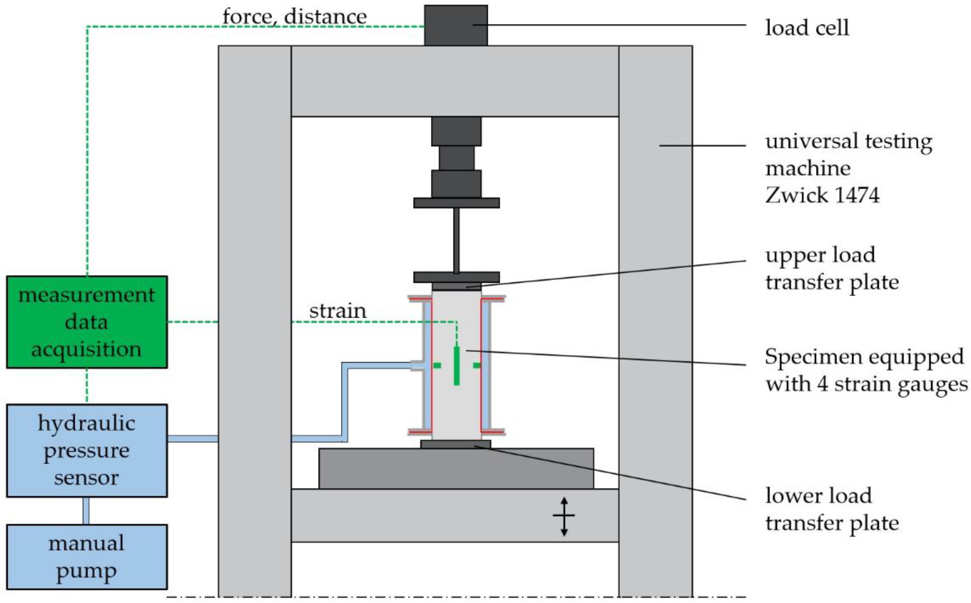
2.3. Experimental Setup and Procedure

Five questions were to be answered through experimental testing:
  • Can a higher compressive strength be achieved?
  • Which fracture criterion is applicable?
  • Which strains occur in the actuated, adaptive state (actuator travel)?
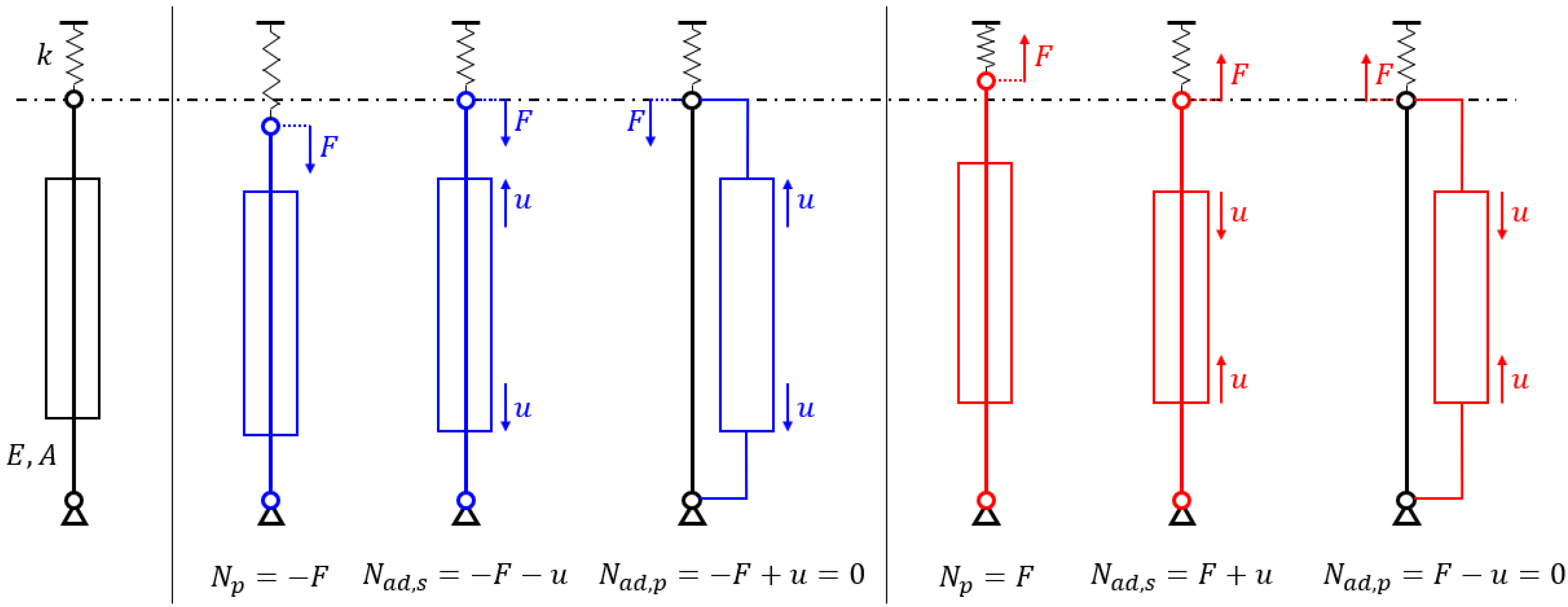
  • Does the enveloping construction (rubber membrane and steel) influence the stiffness or strain? Does it participate in the passive load transfer?
  • Are there differences in the fracture behavior?
To answer these questions, six test procedures were conceived (Table 2).
For each test series a set of at least three tests were performed. The first two series, P0 and PE, were used to answer question four, i.e., whether the envelope itself has any influence on the structural behavior. In both test series, the specimens were loaded axially until failure. Test series A10 and A20 measure the potential increase in compressive strength in comparison to series P0 for different levels of lateral compression of initially 10 and 20 bar (begin of plastic deformations). However, the specimens were also loaded axially until failure to compare fracture stresses and fracture behaviors of the passive and actuated cylinder. The specimens were first loaded laterally by applying the hydraulic pressure, before loading the cylinder axially. The last two test series, CT (tensile meridian) and CC (compressive meridian) were used to explicitly check the deformations (actuator travel). In test series CT, the specimens were loaded only laterally through the hydraulic pressure of 20 bar and in test series CC the specimens were first loaded axially with a constant force of approximately 10 kN (axial stress of 5 MPa), before applying the lateral hydraulic pressure of 20 bar. Four strain gauges were applied to the cylinders to measure the strain in test series P0, CT and CC (Figure 5). As the CT and CC tests were not performed until failure, but within the elastic range, the same specimens were then used as additional samples in the A20 test series. The hydraulic pressure was applied via a manual pump. An oil pressure sensor (SICK AG, Waldkirch, Germany PBT-RB400SG1SSNAMAOZ) was used to measure the hydraulic pressure. Further displacement measurements were done with an inductive displacement sensor (HBK Germany, Darmstadt, Germany, K-WA-T-020W-32K-K1-F1-2-8) and via the built-in displacement sensor of the test machine (ZwickRoell, Ulm, Germany, Zwick 1474). The machine was also equipped with a load cell to measure the acting force. All test series, where the specimens where loaded until failure were driven force-controlled with 0.1 N/mm²s.

3. Experimental Results

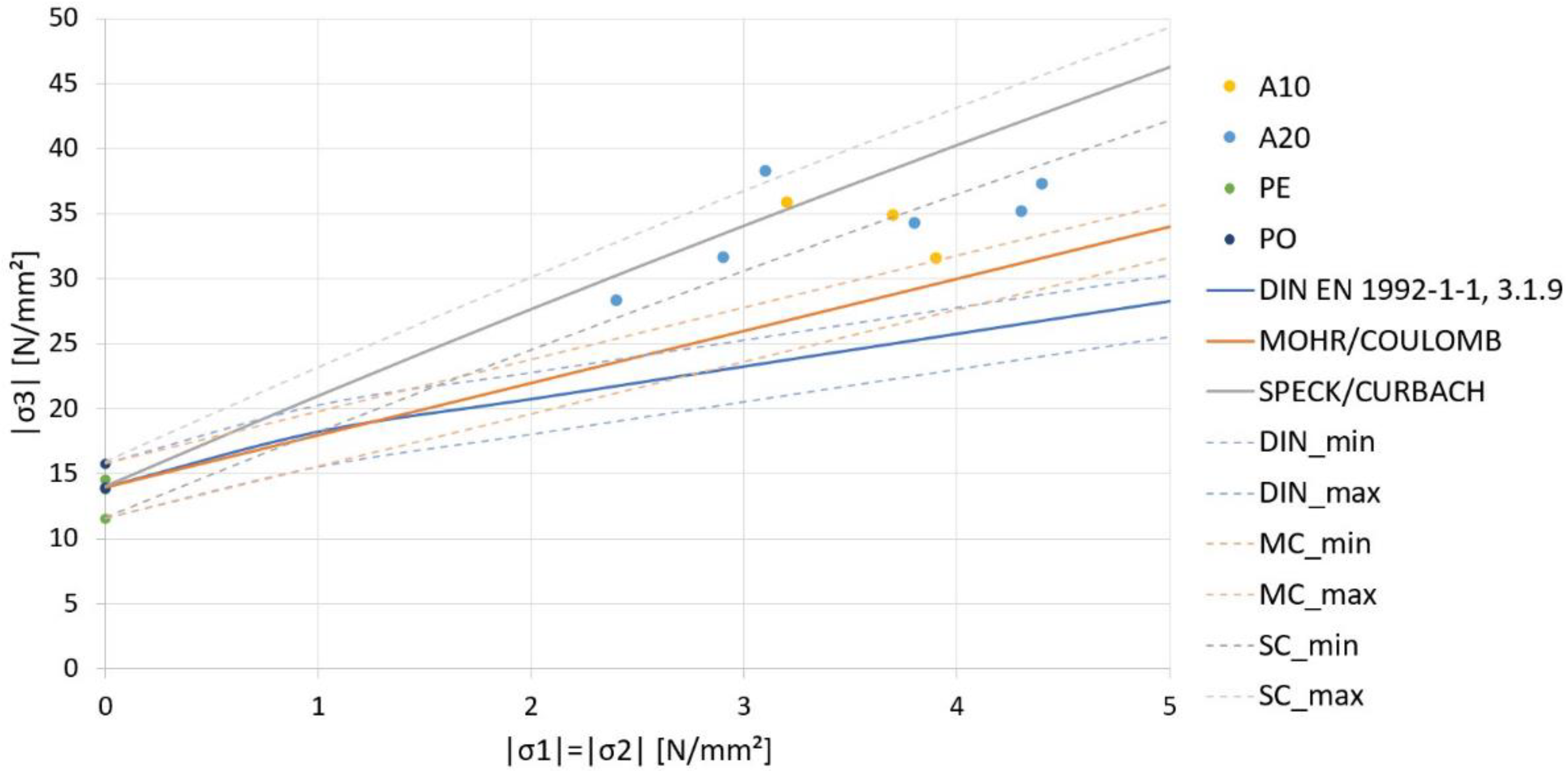
3.1. Mechanisms of Failure and Failure Stresses
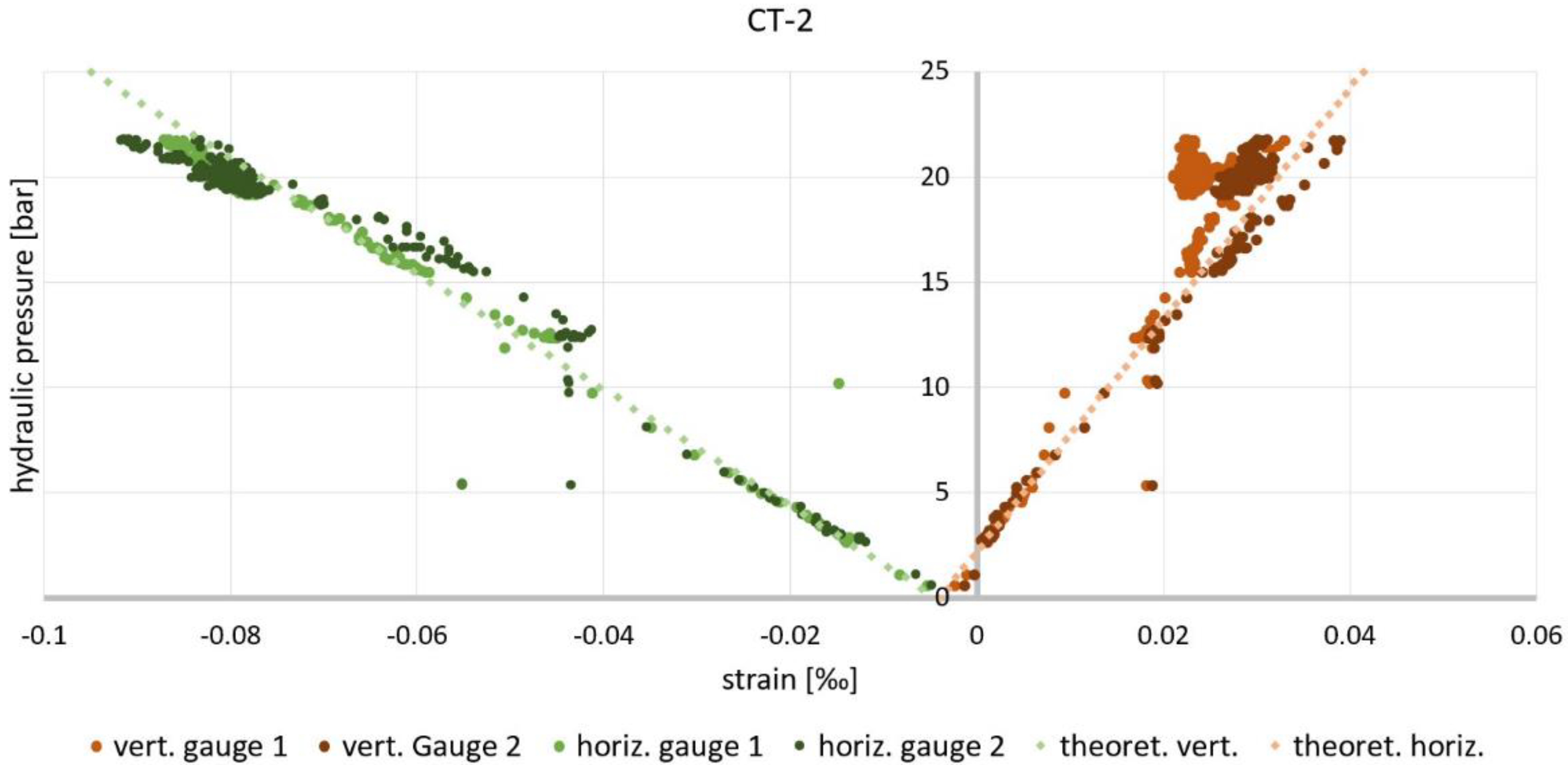
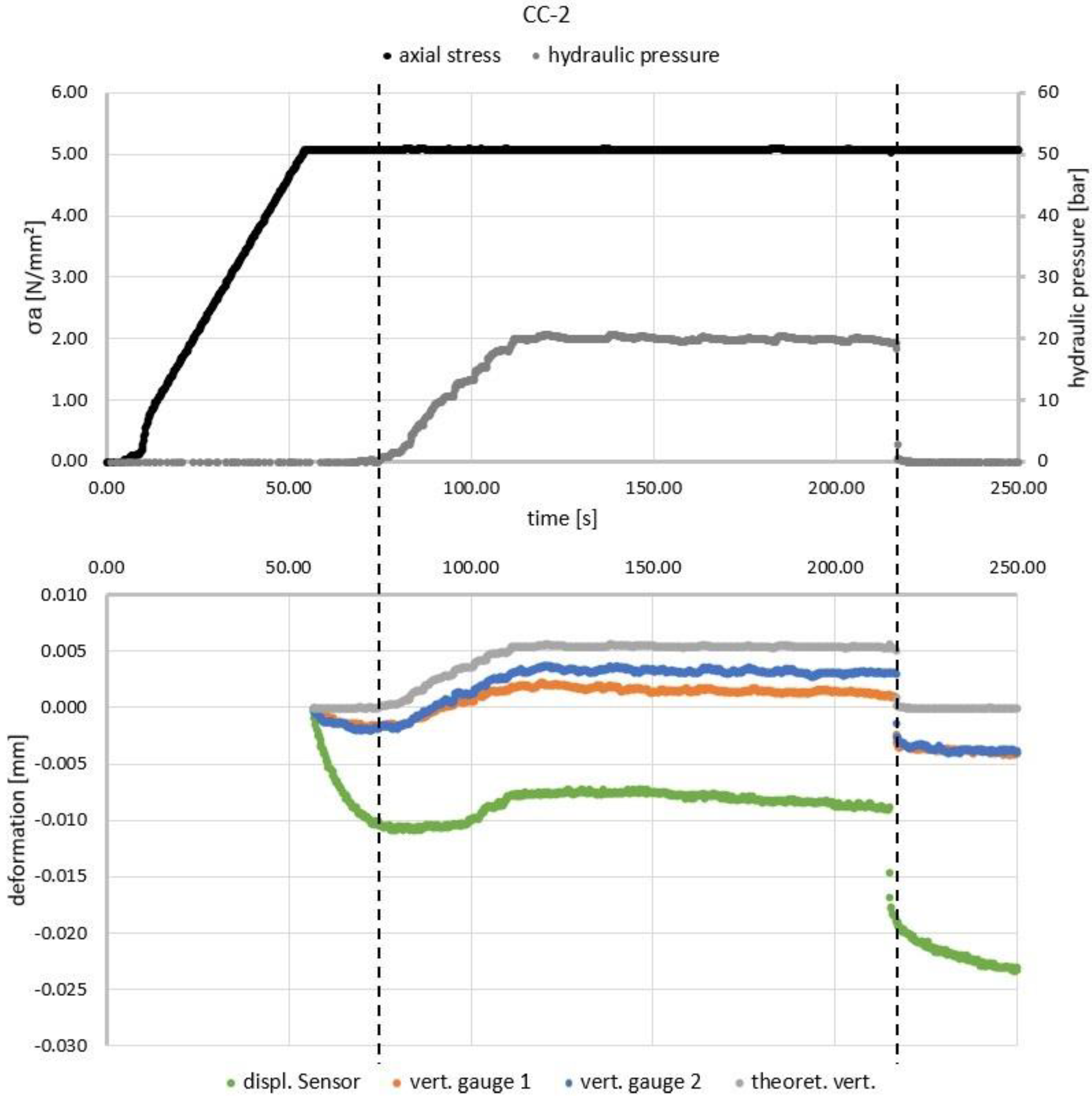
Figure 6 shows the results for the test series P0, PE, A10 and A20, where the specimens were loaded until failure. The results for A20 also include the specimens for series CT and CC, after those series were concluded (Section 3.2). Comparing the results for series P0 and PE shows that the envelope does not contribute in any significant way to the passive load transfer of the concrete column. All six specimens fail at roughly 15 MPa. The fracture mode is that of the expected shear failure (Figure 7a). Series A10 and A20 show the behavior of the adaptive columns under lateral compression of initially 10 or 20 bar respectively. The axial stresses at the transition from elastic to plastic behavior, which correspond to the increased multiaxial compressive strength, are approximately of the respective values according to Equation (1) for the different levels of lateral compression of 10 and 20 bar. All adaptive columns fail at roughly 70 MPa, independently of the initial lateral compression, increasing the fracture stress by a factor of 4.7. At the point of failure, the pressure of the hydraulic fluid is increased up to 40 bar from the initial value. This is due to the fact that the manual pump did not allow for partial pressure release. Therefore, the increasing axial load led to increasing plastic deformations of the concrete cylinder, which reduced the volume of the actuator fluid, thus increasing the hydraulic pressure. The increased hydraulic pressure then reduced the heightened lateral tensile stresses (Figure 1a), resulting in a drawn-out failure in comparison to the passive specimens.
The mechanism of failure of the adaptive tests followed the same procedure: the high plastic deformations allowed the inner O-ring to be pressed out of its position (rupturing at times), allowing the rubber membrane to deform excessively and tear. This allowed the pressure to be released, resulting in a sudden drop in the stabilizing lateral compression and therefore sudden failure. For some specimen, the seals failed at a lower pressure resulting in earlier failure (A20-2, A20-4). The observed fracture mode was again that of a shear failure (Figure 7b); however, during the removal of the specimens from the envelope, further destruction could not be avoided. The darker areas at the ends indicate contact of hydraulic oil and concrete. This contamination is due to the described failure mechanism. The main body of the concrete cylinder, however, remained uncontaminated. Figure 8 shows a comparison of the measured failure stresses against selected established fracture criteria ([24,30]), showing good agreement.

3.2. Deformations

Test series CT and CC were used to validate the lateral and axial deformations of the adaptive concrete column under lateral compression. In series CT the deformation behavior on the tensile meridian was tested by only applying a lateral compression ( σ 1 = 0   MPa > σ 2 = σ 3 = 2   MPa ). It has to be mentioned that the protective coating of the strain gauge cables was damaged in some specimen due to the needed tightness to prevent leakage. This meant that those cables were in contact with the outer steel envelope leading to unusable measurements. Thus, no full set of three complete measurements could be attained for test series CT and CC. However, the undisturbed measurements show good agreement. Figure 9 shows the radial deformation calculated from the measured horizontal strain in comparison to the applied lateral compression in comparison to the theoretical values using a linear elastic material with a Young’s modulus of 22,000 MPa and a Poisson ration of 0.2. The theoretical values were calculated based on the measured hydraulic pressure. The slight changes in the pressure are due to the manual operation of the pump. Overall the measured strains agree well with the theoretical values. In addition, Figure 10 shows the measured tangential and axial strain for the same specimen in comparison to the theoretical values of the mentioned material properties.
Test series CC was conceived to test the behavior on the compressive meridian ( σ 1 = σ 2 = 2   MPa > σ 3 = 5   MPa ). This scenario, where the axial load is greater than the lateral compression, is the most likely use case in which the adaptive column would be actuated in practice. The axial load was first applied and then kept constant for the duration of the test. Figure 11 shows the combined diagrams of the applied loads, measured deformations of the different sensors and the theoretical values calculated from the measured axial and lateral stresses using Hook’s law:
σ = ε · E ,
ε z = 2 ν · σ E ,
l = 2 ν h · p E c ,
with p being the applied lateral hydraulic pressure and E c being the (theoretical) Young’s modulus of the concrete cylinder.
While the measured strains do not agree as well with the previously chosen theoretical values as in the CT-test, the discrepancy is still within reason, especially given the size and concrete quality of the specimen and the scale of the measured strains. A reduction of the vertical deformations under the axial load can be clearly made out, beginning at around 77 s.

4. Discussion

Overall, the experimental tests validate the small-scale prototype of an adaptive concrete column with external actuation. The lateral compression results in a higher compressive strength, which increased with greater hydraulic pressure and resulted in a significantly higher fracture stress. Axial deformations can also be reduced through lateral compression (actuator travel). The fracture failure can be delayed as long as the envelope remains sealed. The sealing is thus one of the critical aspects of the design, which means that particular attention has to be paid to its design. Since supporting structures are usually designed for 50 or more years, the actuators as a part of the load-bearing component should also be designed for similar periods of use with low maintenance. This is especially true if maintenance is only possible with a great deal of effort, e.g., by integrating the actuator into the component cross-section. As long as the pressure chamber of the actuator is not designed with an integral or integrating construction method, i.e., as a single-material component, it can be assumed that the sealing will not achieve such a service life. One possibility might be to substitute the membrane tube with a tubular steel sheet welded to the circular ring plates at either end. This would greatly improve the sealing; however, the steel tube would have to be thin enough to transfer the lateral hydraulic pressure to the concrete column, but thick enough to withstand the axial tension. The presented design should be scalable to realistic dimensions without many changes. The circular ring plates at the ends may need to be strengthened, for example through welded ribs to keep them from deforming excessively under higher hydraulic pressures and the enveloping membrane should be strengthened at the bends. Reinforcements may be required to avoid cracking of the concrete in the cases where the lateral hydraulic pressure is not applied (passive state) or lower than the tensile stresses from axial loading (cf. Section 1.2). Further research is therefore required to evaluate the effects of and need for reinforcement. One of the next steps is thus the study of a real-scale prototype to also study and validate the construction process.
All four design premises were kept: the ends can be connected to adjacent elements in (reinforced) concrete, the envelope by itself did not contribute to the axial load transfer, the concrete remained uncontaminated by the hydraulic oil (until failure), and all construction elements can be easily separated and reused in principle. Further investigation is needed regarding the application potential in civil engineering structures. However, this can be estimated using the following formulas. The maximum deformation of an axially loaded column of height h , without considering any safety factors, is equal to:
l max = f ck E c · h .
Assuming a height of 3.5 m, a common height of a story, this results in a maximum axial deformation in the range of 2.3 mm (C20/25) to 4.7 mm (C50/60), at the point of failure (Table 1). Solving Equation (5) for p and substituting Equation (6) yields a formula to estimate the required lateral hydraulic pressure to compensate these deformations:
p max = f c 2 ν   ,
resulting in hydraulic pressures in the range of 50 MPa (C20/25) to 125 MPa (C50/60). While 50 MPa (500 bar) is reasonably generable, 125 MPa (1250 bar) may require additional installation effort and safety measures. Furthermore, the effect of an increased compressive strength is less pronounced in concrete of higher strength [30]. Another assessment can be done using Barlow’s formula:
σ φ = p · d + 2 s + t 2 t ,
σ φ being the tangential stress in the (steel) envelope, d the diameter of the concrete cylinder, t the thickness of the (steel) envelope and s being the space of the cavity filled with the actuator fluid. As can be seen from Equation (8), the tangential stresses increase in proportion with the overall diameter of the adaptive column. Thus, with an increasing diameter, a thicker or higher strength envelope is needed for the same lateral hydraulic pressure. The space of the cavity should therefore be kept as minimal as possible.
Another idea might be to use the hydraulic pressure acting on the circular ring plates at the end faces to press against connecting ceiling slabs to create an uplifting force, reducing the compressive axial force in the concrete column (Figure 2, parallel actuation). Generally, the application potential is highly dependent on the building or load-bearing structure for which this actuator is being considered. Possible criteria are-among others-the governing actuation goal (reduction of deformations or increase in compressive strength), the difference in stress in the passive an actuated state, or how often the actuators need to be actuated. Further research is needed where this concept is applied in case studies of different types, including an analysis of possible material savings and required actuation energy and the corresponding emissions. Lastly, as mentioned previously, the current design only allows for a lateral compression resulting in axial extension. A possible expansion would be to add a mechanism that also allows for axial retraction. Keeping the low tensile strength of concrete in mind, this mechanism should act as a parallel actuator (Figure 2), to load the central concrete cylinder in compression.

5. Conclusions

This paper presents four new concepts for linear actuators with a concrete column as structural base. After a brief discussion, one promising concept is further analyzed and experimentally validated on a prototype scale: through lateral compression, the compressive strength of a central concrete column can be increased, while simultaneously reducing axial deformations. The experiments show good agreement with theoretical values, prompting further research into the presented concepts, especially narrowing down their (individual) application potential and the achievable material and emission savings in adaptive civil engineering structures.

Author Contributions

Conceptualization, S.S., M.N. and T.B.; Data curation, S.S.; Formal analysis, S.S.; Funding acquisition, H.B., L.B. and W.S.; Methodology, S.S.; Project administration, H.B., L.B. and W.S.; Supervision, H.B., L.B. and W.S.; Validation, S.S.; Visualization, S.S.; Writing–original draft, S.S.; Writing–review & editing, S.S., M.N., T.B., H.B., L.B. and W.S. All authors have read and agreed to the published version of the manuscript.

Funding

Funded by the Deutsche Forschungsgemeinschaft (DFG, German Research Foundation), Project-ID 279064222–SFB 1244. The authors are grateful for the generous support.

Institutional Review Board Statement

Not applicable.

Informed Consent Statement

Not applicable.

Data Availability Statement

The data presented in this study are available on request from the corresponding author.

Acknowledgments

Simon Steffen would like to thank Teresa Lehmann and Rebekka Zeiff for their extensive help in the development and design of the prototypes, as well as in the preparation and conduct of the experiments and the subsequent analysis and data processing, which led to the presented results.

Conflicts of Interest

The authors declare no conflict of interest.

References

  1. Scrivener, K.L.; Kirkpatrick, R.J. Innovation in Use and Research on Cementitious Material. Cem. Concr. Res. 2008, 38, 128–136. [Google Scholar] [CrossRef]
  2. Scrivener, K.L.; John, V.M.; Gartner, E.M. Eco-Efficient Cements: Potential Economically Viable Solutions for a Low-CO2 Cement-Based Materials Industry. Cem. Concr. Res. 2018, 114, 2–26. [Google Scholar] [CrossRef]
  3. Peduzzi, P. Sand, Rarer than One Thinks. UNEP Global Environ. Alert Serv. (GEAP) 2014, 11, 208–218. [Google Scholar]
  4. Weidner, S.; Mrzigod, A.; Bechmann, R.; Sobek, W. Graue Emissionen im Bauwesen—Bestandsaufnahme und Optimierungsstrategien. Beton- und Stahlbetonbau 2021. [Google Scholar] [CrossRef]
  5. Sobek, W. Ultra-Lightweight Construction. Int. J. Space Struct. 2016, 31, 74–80. [Google Scholar] [CrossRef]
  6. International Resource Panel. Decoupling Natural Resource Use and Environmental Impacts from Economic Growth; UNEP, Ed.; UNEP: Nairobi, Kenya, 2011; ISBN 978-92-807-3167-5. [Google Scholar]
  7. United Nations Environment Programme The Emissions Gap Report 2019; UNEP: Nairobi, Kenya, 2019; ISBN 978-92-807-3766-0.
  8. Geiger, F.; Gade, J.; von Scheven, M.; Bischoff, M. A Case Study on Design and Optimization of Adaptive Civil Structures. Front. Built Environ. 2020, 6, 94. [Google Scholar] [CrossRef]
  9. Senatore, G.; Duffour, P.; Winslow, P. Synthesis of Minimum Energy Adaptive Structures. Struct. Multidisc. Optim. 2019, 60, 849–877. [Google Scholar] [CrossRef] [Green Version]
  10. Reksowardojo, A.P.; Senatore, G.; Smith, I.F.C. Design of Structures That Adapt to Loads through Large Shape Changes. J. Struct. Eng. 2020, 146, 04020068. [Google Scholar] [CrossRef]
  11. Ostertag, A.; Dazer, M.; Bertsche, B.; Schlegl, F.; Albrecht, S.; Leistner, P.; Gienger, A.; Wagner, J.; Tarín, C.; Sawodny, O. Reliable Design of Adaptive Load-Bearing Structures with Focus on Sustainability. In Proceedings of the 30th European Safety and Reliability Conference and 15th Probabilistic Safety Assessment and Management Conference, Venice, Italy, 1–5 November 2020; pp. 4703–4710. [Google Scholar]
  12. Zilch, K.; Zehetmaier, G. Bemessung im Konstruktiven Betonbau; Springer: Berlin/Heidelberg, Germany, 2010; ISBN 978-3-540-70637-3. [Google Scholar]
  13. Senatore, G.; Duffour, P.; Winslow, P.; Wise, C. Shape Control and Whole-Life Energy Assessment of an ‘Infinitely Stiff’ Prototype Adaptive Structure. Smart Mater. Struct. 2018, 27, 015022. [Google Scholar] [CrossRef] [Green Version]
  14. Sobek, W.; Teuffel, P. Adaptive Systems in Architecture and Structural Engineering. In Proceedings of the SPIE 8th Annual International Symposium on Smart Structures and Materials, Newport Beach, CA, USA, 4–8 March 2001; pp. 36–45. [Google Scholar]
  15. Senatore, G.; Duffour, P.; Winslow, P. Energy and Cost Assessment of Adaptive Structures: Case Studies. J. Struct. Eng. 2018, 144, 04018107. [Google Scholar] [CrossRef]
  16. Neuhaeuser, S.; Weickgenannt, M.; Witte, C.; Haase, W.; Sawodny, O.; Sobek, W. Stuttgart SmartShell—A Full Scale Prototype of an Adaptive Shell Structure. J. Int. Assoc. Shell Spat. Struct. 2013, 54, 259–270. [Google Scholar]
  17. Reksowardojo, A.P.; Senatore, G.; Smith, I.F.C. Experimental Testing of a Small-Scale Truss Beam That Adapts to Loads Through Large Shape Changes. Front. Built Environ. 2019, 5, 93. [Google Scholar] [CrossRef]
  18. Sobek, W.; Teuffel, P.; Landauer, A. Stuttgarter Träger; Institute for Lightweight Structures (ILEK), University of Stuttgart: Stuttgart, Germany, 2002. [Google Scholar]
  19. Senatore, G.; Duffour, P.; Winslow, P. Exploring the Application Domain of Adaptive Structures. Eng. Struct. 2018, 167, 608–628. [Google Scholar] [CrossRef]
  20. Kelleter, C.; Burghardt, T.; Binz, H.; Blandini, L.; Sobek, W. Adaptive Concrete Beams Equipped with Integrated Fluidic Actuators. Front. Built Environ. 2020, 6, 91. [Google Scholar] [CrossRef]
  21. Weidner, S.; Steffen, S.; Sobek, W. The Integration of Adaptive Elements into High-Rise Structures. Int. J. High-Rise Build. 2019, 8, 95–100. [Google Scholar] [CrossRef]
  22. Bleicher, A. Aktive Schwingungskontrolle einer Spannbandbrücke mit pneumatischen Aktuatoren. Bautechnik 2012, 89, 89–101. [Google Scholar] [CrossRef] [Green Version]
  23. Burghardt, T.; Kelleter, C.; Bosch, M.; Bachmann, M.; Binz, H.; Blandini, L.; Sobek, W. Adaptive Beams with Integrated Thermal Actuator. In Proceedings of the International Conference and Exhibition on New Actuator Systems and Applications 2021, Online Event, 17 February 2021; VDE Verlag GmbH: Berlin, Germany, 2021; Volume 98, pp. 341–343. [Google Scholar]
  24. DIN. Eurocode 2: Design of Concrete Structures—Part 1-1: General Rules and Rules for Buildings (Includes Corrigendum AC:2010) Englisch Translation of DIN EN 1992-1-1:2011-01; DIN: Berlin, Germany, 2011. [Google Scholar]
  25. Jonas, F.; Knippers, J. Tragverhalten von Betondruckgliedern mit Umschnürung durch geflochtene und gewickelte Carbonrohre: Tragfähigkeitssteigerung durch Aktivierung eines mehraxialen Spannungszustands im Beton. Beton-Und Stahlbetonbau 2017, 112, 517–529. [Google Scholar] [CrossRef]
  26. Käseberg, S.; Holschemacher, K.; Curbach, M. Zum Tragverhalten CFK-umschnürter Stahlbetonstützen mit Kreisquerschnitt. Beton-Und Stahlbetonbau 2018, 113, 505–514. [Google Scholar] [CrossRef]
  27. Janke, L.; Czaderski, C.; Ruth, J.; Motavalli, M. Experiments on the Residual Load-Bearing Capacity of Prestressed Confined Concrete Columns. Eng. Struct. 2009, 31, 2247–2256. [Google Scholar] [CrossRef]
  28. Kaeseberg, S.; Messerer, D.; Holschemacher, K. Assessment of Standards and Codes Dedicated to CFRP Confinement of RC Columns. Materials 2019, 12, 2390. [Google Scholar] [CrossRef] [Green Version]
  29. Hampel, T.; Speck, K.; Scheerer, S.; Ritter, R.; Curbach, M. High-Performance Concrete under Biaxial and Triaxial Loads. J. Eng. Mech. 2009, 135, 1274–1280. [Google Scholar] [CrossRef]
  30. Speck, K.; Curbach, M. Ein einheitliches dreiaxiales Bruchkriterium für alle Betone. BUST 2010, 105, 233–243. [Google Scholar] [CrossRef]
  31. Ottosen, N.S. A Failure Criterion for Concrete. J. Eng. Mech. Div. 1977, 103, 527–535. [Google Scholar] [CrossRef]
  32. Rogge, A. Materialverhalten von Beton Unter Mehrachsiger Beanspruchung; Technische Universität München: München, Germany, 2003. [Google Scholar]
  33. Steffen, S.; Weidner, S.; Blandini, L.; Sobek, W. Using Influence Matrices as a Design and Analysis Tool for Adaptive Truss and Beam Structures. Front. Built Environ. 2020, 6, 83. [Google Scholar] [CrossRef]
  34. Weidner, S.; Kelleter, C.; Sternberg, P.; Haase, W.; Geiger, F.; Burghardt, T.; Honold, C.; Wagner, J.; Böhm, M.; Bischoff, M.; et al. The Implementation of Adaptive Elements into an Experimental High-Rise Building. Steel Constr. 2018, 11, 109–117. [Google Scholar] [CrossRef]
  35. Böhm, M.; Wagner, J.L.; Steffen, S.; Gade, J.; Geiger, F.; Sobek, W.; Bischoff, M.; Sawodny, O. Input Modeling for Active Structural Elements—Extending the Established FE-Work? Ow for Modeling of Adaptive Structures. In Proceedings of the 2020 IEEE/ASME International Conference on Advanced Intelligent Mechatronics (AIM), Boston, MA, USA, 6–9 July 2020; pp. 1595–1600. [Google Scholar]
  36. Zupan, M.; Ashby, M.F.; Fleck, N.A. Actuator Classification and Selection—The Development of a Database. Adv. Eng. Mater. 2002, 4, 933–940. [Google Scholar] [CrossRef]
  37. Isermann, R. Mechatronische Systeme: Grundlagen, 2nd ed.; Springer: Berlin/Heidelberg, Germany, 2008; ISBN 978-3-540-32336-5. [Google Scholar]
  38. Dahl, K.K. The Calibration and Use of a Triaxial Cell; Technical University of Denmark, Department of Civil Engineering: Lyngby, Denmark, 1992; ISBN 978-87-7740-105-3. [Google Scholar]
  39. Hobbs, D.W. Strength of Concrete under Combined Stress. Cem. Concr. Res. 1971, 1, 41–56. [Google Scholar] [CrossRef]
  40. Speck, K. Beton unter Mehraxialer Beanspruchung (Concrete under Multiaxial Loading Conditions); Universität Dresden: Dresden, Germany, 2007. [Google Scholar]
  41. Simsch, G. Tragverhalten von Hochbeanspruchten Druckstützen Aus Hochfestem Normalbeton (B 65-B 115); VDI Verlag: Düsseldorf, Germany, 1995; ISBN 3-18-312704-0. [Google Scholar]
Figure 1. (a) Schematic load transfer of an axial compressive load in normal-strength concrete on the meso-level; (b) Three-dimensional envelope for different multiaxial loading states. Based on [12].
Actuators 10 00273 g001
Figure 2. Schematic of an actuated column with Young’s Modulus E, cross-section A and constraining stiffness k, from left to right: static system; column under external compressive load F; deformation compensation through serial actuation u and resulting superposition of compressive normal forces N; deformation compensation through parallel actuation and resulting distribution of normal forces in the column and actuator; column under external tensile load; deformation compensation through serial actuation and resulting superposition of tensile normal forces; deformation compensation through parallel actuation and resulting distribution of normal forces in the column and actuator.
Actuators 10 00273 g002
Figure 3. Concepts for adaptive concrete columns. (a) Central cylindrical passive concrete column as base; (b) serial axial actuation; (c) parallel internal axial actuation; (d) internal lateral compression actuation; (e) external lateral compression actuation.
Actuators 10 00273 g003
Figure 4. Design of the prototype.
Actuators 10 00273 g004
Figure 5. Schematic of the test setup for test series A10, A20 and CC.
Actuators 10 00273 g005
Figure 6. Stress-deformation diagrams for test series P0, PE, A10 and A20, including the applied hydraulic pressure for test series A10 and A20.
Actuators 10 00273 g006
Figure 7. Typical fracture pattern; (a) test series P0 and PE; (b) test series A10 and A20.
Actuators 10 00273 g007
Figure 8. Comparison of the measured increase in fracture stress σ3 vs. different fracture criteria [24,30] based on the measured uniaxial fracture stress |σ1|=|σ2|.
Actuators 10 00273 g008
Figure 9. Comparison of the measured (test CT−2) and theoretical ( E c = 22 , 000   MPa ,   ν = 0.2 ) horizontal deformations (strain) with respect to the applied hydraulic pressure.
Actuators 10 00273 g009
Figure 10. Comparison of the measured vertical and horizontal strain (test CT−2) against theoretical values ( E c = 22 , 000   MPa ,   ν = 0.2 ).
Actuators 10 00273 g010
Figure 11. Sequential loading for test CC−2 and vertical deformations calculated from measured strain (strain gauges), measured displacement (inductive displacement sensor) and theoretical deformations ( E c = 22 , 000   MPa ,   ν = 0.2 ).
Actuators 10 00273 g011
Table 1. Excerpt of strength-based classifications of concrete according to European codes [24]; characteristic compressive strength f c k , characteristic tensile strength f c t m , Young’s modulus E c .
C20/25C30/37C40/50C50/60
f c k     MPa 20304050
f c t m MPa 2.22.93.54.1
E c   MPa 30,00033,00035,00037,000
Table 2. Overview of the testing program.
Test SeriesDescriptionTest Procedure (Over Time t)
P0passive; concrete cylinder only; axially loaded (F) until failure
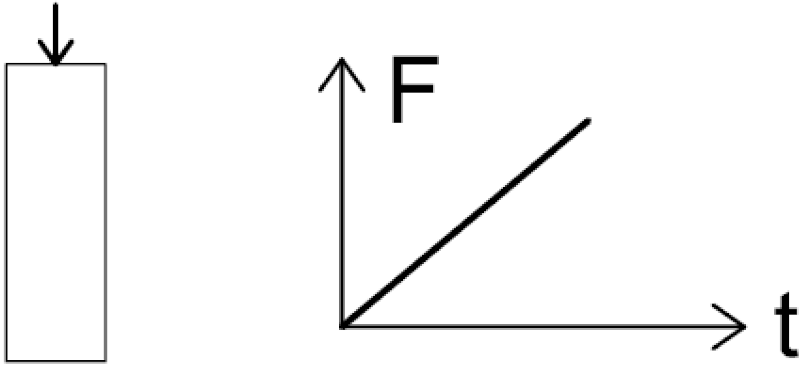
 Actuators 10 00273 i001
PEpassive; concrete cylinder integrated into envelope; axially loaded (F) until failure
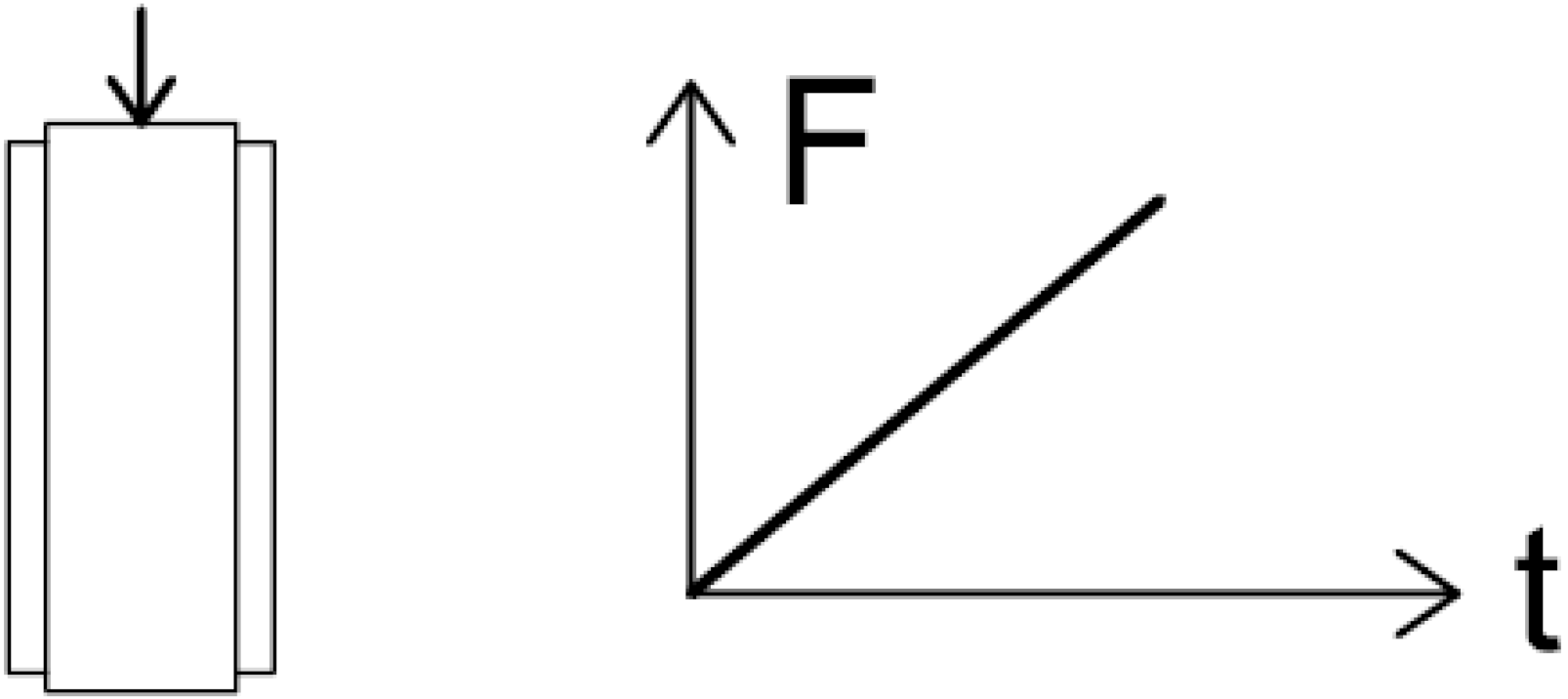
 Actuators 10 00273 i002
A10adaptive; lateral hydraulic pressure (p) of 10 bar; axially loaded (F) until failure
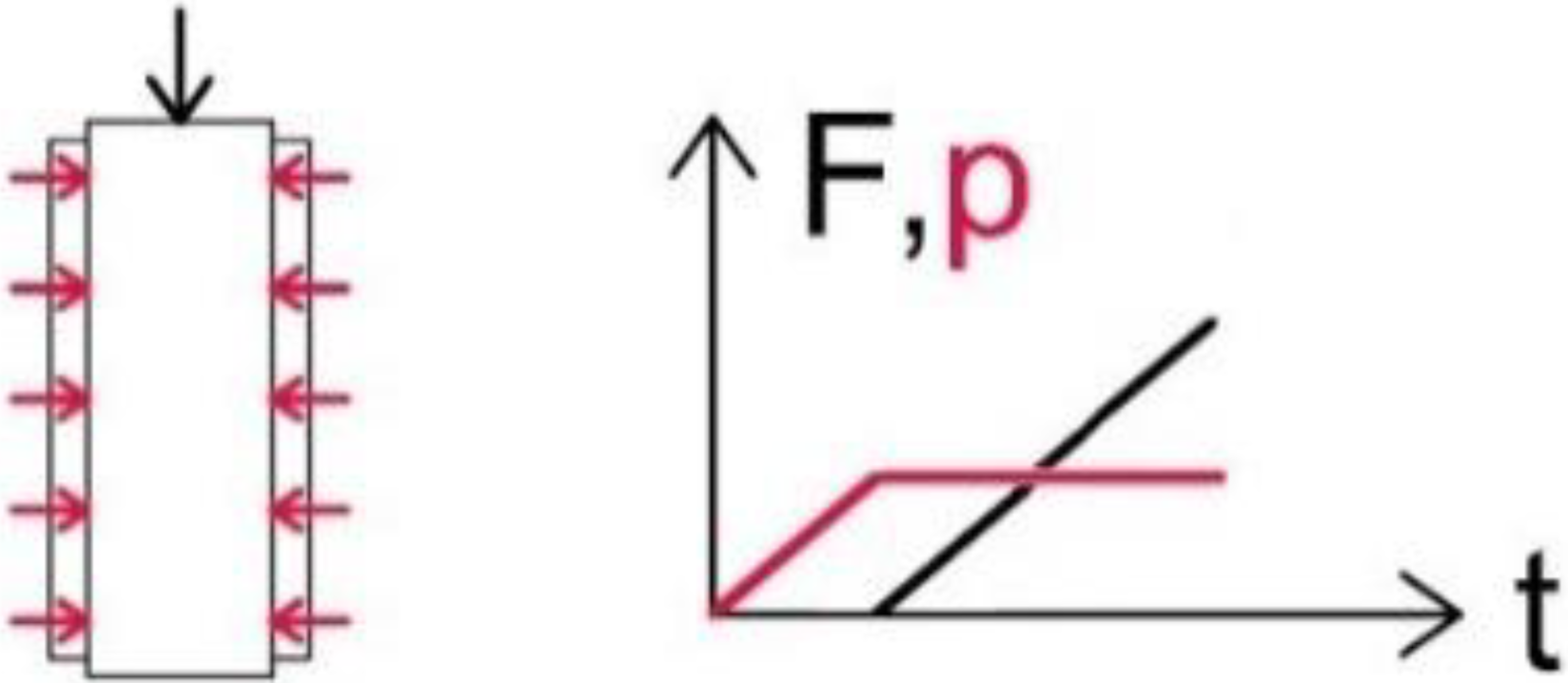
 Actuators 10 00273 i003
A20adaptive; lateral hydraulic pressure (p) of 20 bar; axially loaded (F) until failure Actuators 10 00273 i004
CThydraulic pressure (p) of 20 bar only; elastic range Actuators 10 00273 i005
CCcombined axial load (F) of ~10 N (5 MPa) and lateral hydraulic pressure (p) of 20 bar; elastic range Actuators 10 00273 i006
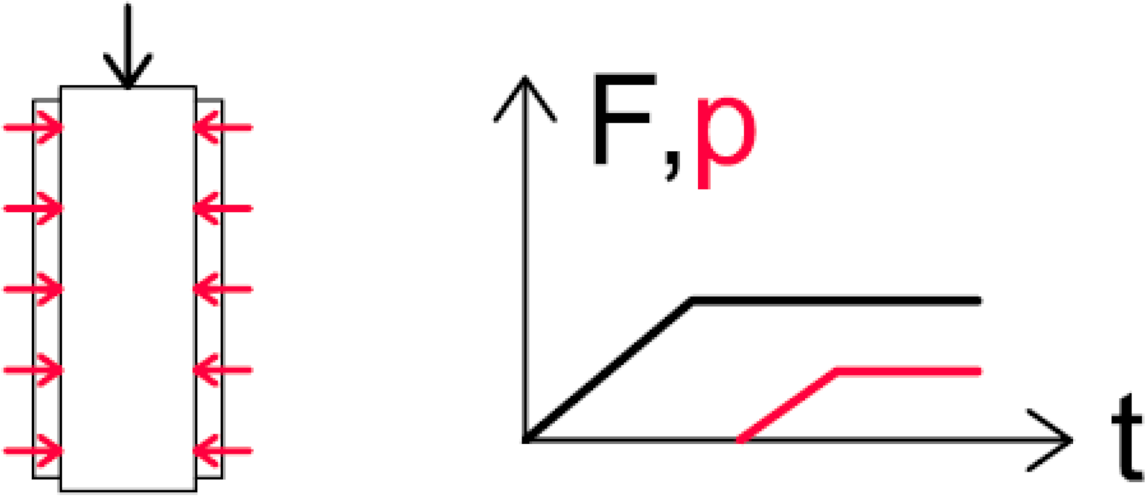
Publisher’s Note: MDPI stays neutral with regard to jurisdictional claims in published maps and institutional affiliations.

