1. Introduction
OpenROV is a community developed remotely operated submersible vehicle designed to make underwater exploration and education affordable. The latest version is OpenROV 2.8. The main controller on the ROV is a BeagleBone Black Linux-based computer; it has a webcam for navigation and inspection purposes. In addition to hobbyists and recreational users, OpenROV found some applications in the science and research domains. For example, in underwater environment monitoring, exploration, and subsea ROV development [
1,
2]. Grippers are an essential component of underwater exploration vehicles. Gripper types vary in mechanical design, actuation methods, and motion control. For example, two- and three-finger, compliant, needle, o-ring, etc. Actuation methods include servo motor, magnetic, pneumatic, and hydraulic power. To perform grip force control, sensors are required. Such as tip force sensors, vacuum pressure, and motor current-draw sensors. The aim of this work is to design a multi-fingered gripper module for the OpenROV submersible. The gripper module consists of three fingers, each finger consists of two independently actuated links. The total length of both links was arbitrarily selected to be 13.8 cm. Moreover, internal actuation of these links is required; all actuators should be placed inside the module. Mechanical design, forward kinematics, and the workspace are presented, in addition to an estimation of the maximum force exerted by the fingertips. Furthermore, the fingertip link position and dynamic response are modeled and simulated as a function of input torque to this link. The model is of second order and the stability analysis showed a stable system.
2. Related Work
OpenROV is an open-source low-cost tele-robotic submarine developed to ease subsea exploration. It is controlled by a portable groundstation connected via a tether to the submarine and powered using onboard batteries. The OpenROV has dimensions of 15 × 20 × 30 cm and weighs 2.6 kg. It has a camera with audio input, LED lights, and can dive to a maximum depth of 100 m. In general, an end effector is a device attached at the moving end of the manipulator. It allows a robot to interact with the outside environment and perform its functions. An end effector could be a welding torch, a paint sprayer, or a gripper, for example. Robotic grippers have been the subject of extensive research over the past decades [
3,
4,
5].
One way to categorize grippers is to divide them into rigid grippers and compliant grippers. Rigid grippers employ a wide range of mechanisms to grasp the target object. These mechanisms include: linkage type; gear and rack type; cam-actuated type; screw-driven type; rope and pulley type [
4]. For feedback, a rigid gripper may rely on haptics, an external visual system, or mounted cameras on the robotic manipulator. An example of the latter is the eye-in-hand design [
6]. Rigid grippers have diverse applications including industrial, space, agricultural, and many others [
7,
8].
On the other hand, compliant grippers, which have been the focus of great research efforts recently, use different approaches to grasp fragile objects or objects of unknown shape. Examples of compliant grippers are numerous. Some designs employ fingers with multiple links that surround and conform to the shape of the object. Other designs rely on the particle jamming phenomena [
5]. Moreover, some gripper designs utilize soft actuators, nano-generators, and other NEMS components based on piezoelectric and magnetic properties of special materials to achieve soft and flexible compliance with the shape of the target objects [
9,
10]. For increased versatility and adaptability, some designs use a combination of rigid and soft modules in addition to using soft material to protect sensitive objects that will be grasped [
11].
Other compliant designs depend on a combination of grasping methods, pinch grasping, and suction grasping. For example, a five-fingered gripper with a palm and suction cups at the tip of each finger as presented in Ref. [
12]. Tendon wires are also widely used in compliant grippers. The researchers of [
13] present a two-fingered, flexible joint, variable stiffness gripper and tendon wire with interpenetrating phase composites (IPCs) materials. Furthermore, improved grasp adaptability could be attained by using a soft pneumatic gripper with variable stiffness grip [
14].
Most of the modern grippers in sensitive applications integrate tactile sensing and haptic feedback on the fingertips of the gripper and in some cases, data from external vision systems [
15]. Another indirect method to measure the force at the tips of soft grippers is to infer it using a kinematic model. This approach is vital for medical applications where less invasive designs are required [
16]. These technologies provide a way to control the forces exerted on the object and can be very important when the target object is fragile. An example of tactile sensing implementation using strain gauges is discussed in Ref. [
17]; however, few compliant and soft gripper designs do not rely on haptic feedback to adjust to the shape and the needed force to grip food objects. They mostly rely on special mechanical linkage designs and current-based servo motor torque sensing and control [
18]. The gripper designed in this work does not include force sensors on the tips, nor monitors the servo motor electrical current, even though this would be beneficial. Instead, the design assumed a camera installed at the bottom of the ROV for surveillance tasks and simultaneously serves as a system to monitor the gripper fingers and the moment the object has been grasped. This design is more cost-effective than installing tip sensors. Between the rigid and compliant grippers categories, “in-between” hybrid designs exist. These designs use flexible fingers or linkages with variable stiffness to accomplish an adaptive and firm grasp [
19,
20,
21,
22]. The AMADEUS project (Advanced Manipulator for Deep Underwater Sampling) is a great example of subsea robotics [
23]. It included the design of a three-fingered gripper with passive compliance where each finger consists of three elastic cylindrical bellows. Utilizing different values of the hydraulic pressure for each bellow causes them to extend in different lengths, which in turn causes the finger to conform and grasp the object. The gripper also had haptic feedback via strain gauges on the tip of the fingers to sense the force.
The gripper design and simulation in this work differ in several ways from the reviewed systems. The three rigid servo-controlled links could use current sensing to measure grip force; however, the solution here is using image processing through an existing camera feed on the ROV belly. Since potential items on the seafloor can have varying weight, it makes sense to not rely on force sensors, since items might slip or get crushed if a certain target force is programmed. The design is similar to an inverted pick-and-place delta robot used in industry, but without the connecting plate that usually houses the end effector. An example end effector in the food industry may be air-suction based. In recent designs, the three links move independently and thus offer the agility of the delta robot and the ability to grip objects from different points in three dimensions.
3. Materials and Methods
3.1. Mechanical Design
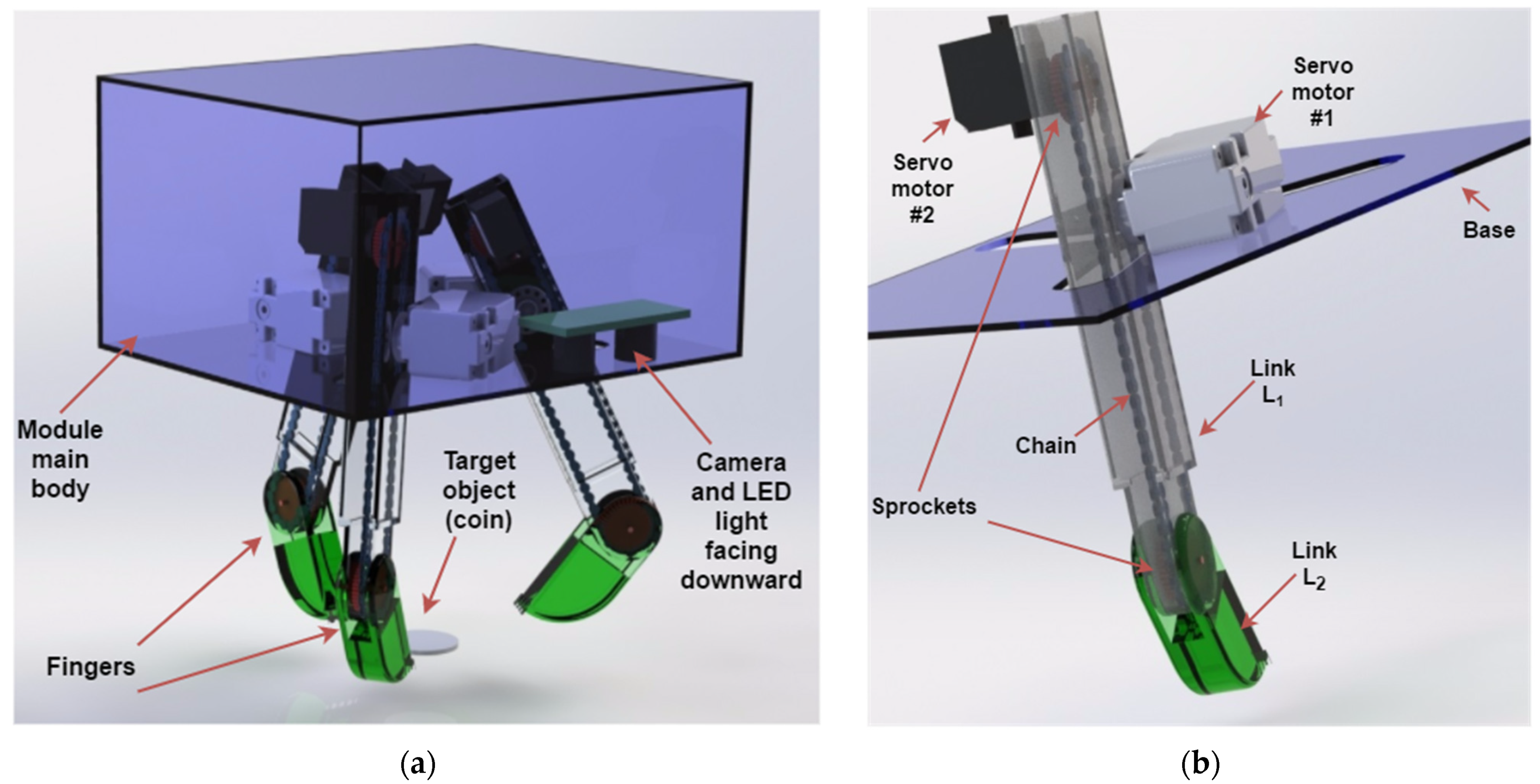
The gripper module was attached to the underside of the OpenROV. This rigid-type gripper consists of three fingers; forming a three-points-of-contact grasp that provides a stable and firm grip on the targeted object. A camera and an LED light were placed inside the module facing downward. The camera acts as the sole sensor and provides the needed feedback about the target object position (
Figure 1a). The module also housed the batteries required to power its electrical components. The battery model used was the MV5450 Multi-Voltage LiPo Battery Pack from MAXAmp in two parallel cells configuration. The controller used was the Raspberry PI 3. The Raspberry PI controller is sufficient for this application and it is already being used in underwater applications (the main controller for OpenROV Trident is Raspberry PI 3) [
24]. Two servo motors were used for each finger, the first motor was fixed to the module and will actuate link
. The second motor was mounted on link
(i.e., it will move with
), the motion was transmitted from the second motor to the axis of rotation of link
via a chain-sprocket mechanism. The chain ran inside link
, and the two sprockets had the same diameter.
Figure 1b illustrates this configuration. Since the first motor would be carrying the second motor, a reasonably smaller motor was selected to actuate the link
. The selected motors were HITEC HS-645 and HS-81 micro servo. The links (
and
) and the module body were fabricated using cast acrylic, which is known for its suitability for water applications, the density of acrylic was 1200 kg/
. SolidWorks mass analysis was used to estimate the masses of these parts.
Table 1 is the bill of materials. It estimates the total cost and mass of the design.
3.2. Forward Kinematics
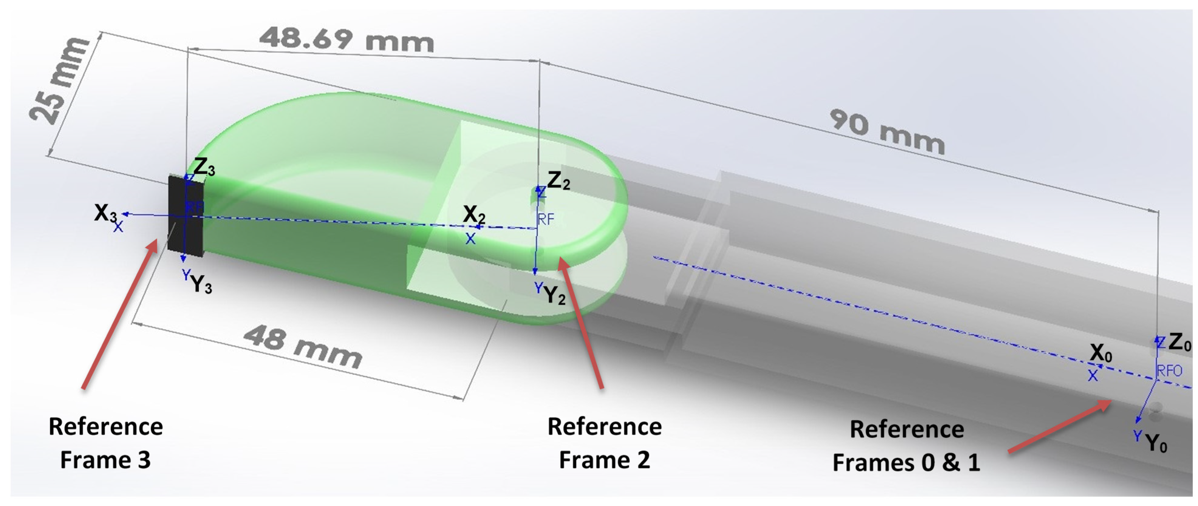
Four reference frames were attached to the finger in order to determine the DH parameters and calculate the forward kinematics. The first reference frame was placed in the origin of the first joint, was aligned with the joint axis. was the perpendicular line between and . were determined using the right-hand rule. was the global origin. The second reference frame coincided with but it was free to rotate with link , was aligned with the joint axis and was the perpendicular line between and . was determined using the right-hand rule. The third reference frame was attached to link , was aligned with the rotation axis and was the perpendicular line between and . was determined using the right-hand rule.
The last reference frame
is placed on the far end of the second link
(i.e., the tip of the finger or the point of contact with the grasped object). For simplicity,
will be parallel to
and
will be aligned with
.
Figure 2. Shows these reference frames along with some important dimensions.
The procedure for attaching the reference frames and the convention used with the DH parameters are adapted from [
25].
Table 2 summarizes the DH parameters.
The homogeneous transformation matrix is given in (1):
After substituting the values from
Table 2 in (1), we get the transformation matrices:
Multiplying these matrices will give the final transformation matrix which relates the coordinates of the tip of the finger to the coordinates of the global origin:
where:
3.3. Workspace
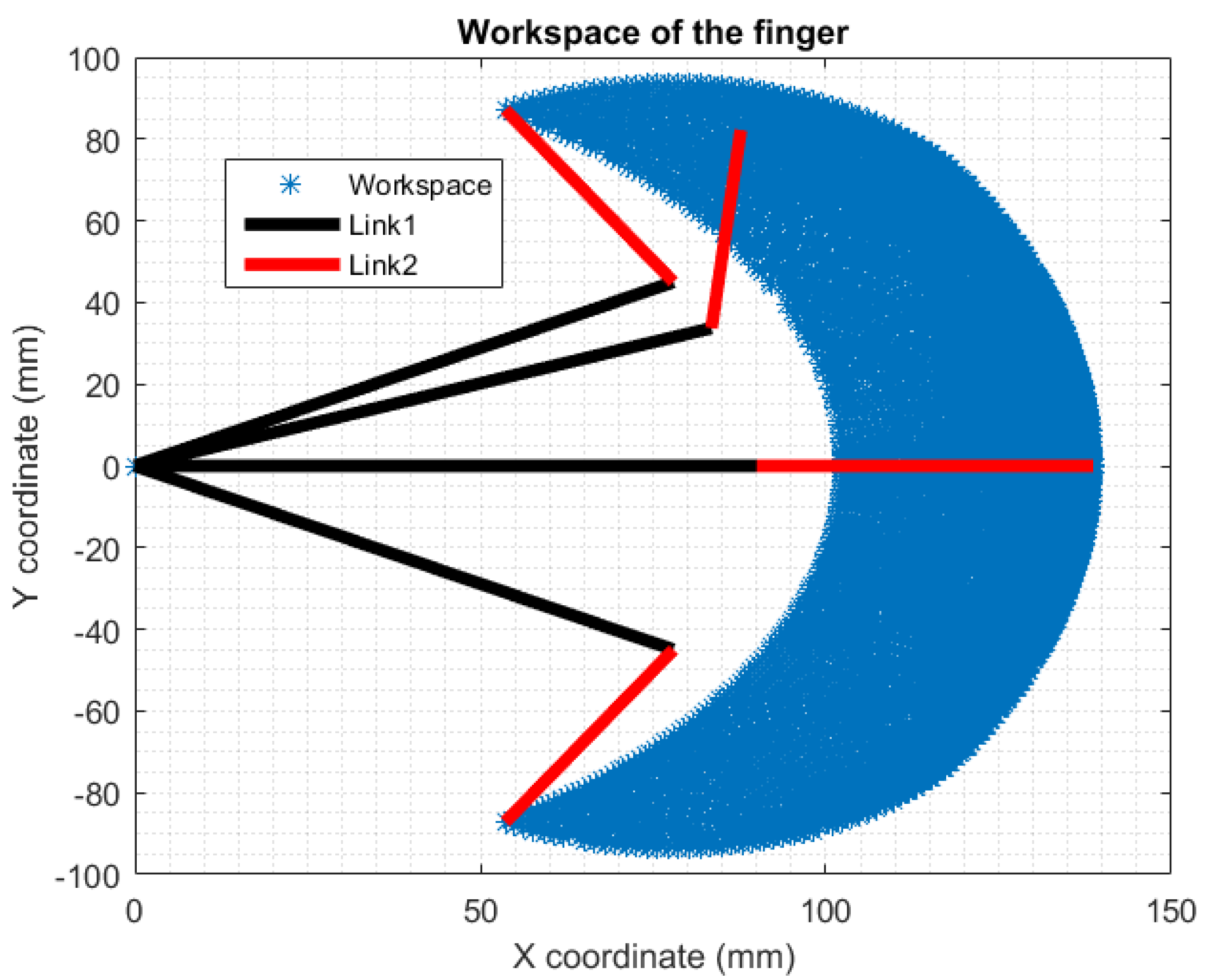
The workspace is the area that can be covered by the manipulator, it can be illustrated by knowing the forward kinematics and the joint limits of the manipulator.
The joint limits are specified by the actuator limits and the physical design of the links. The motors used in this work were capable of doing full rotation, so the only limitation imposed was to prevent collision between different parts of the gripper. Therefore, reasonable joints limits were assumed here: for the first joint, −; for the second joint, −.
A MATLAB script was written to plot the workspace for one finger
Figure 3. The script scanned these joint limits and using (6) and (7) it computed all the possible x and y coordinates. It also plotted the finger in four different poses:
Lower limit:
Upper limit:
Fully extended:
Random pose:
3.4. Force Analysis
The objective of this force analysis is to estimate the maximum force exerted by the finger at its tip when fully extended.
Newton–Euler’s equations were used to calculate the linear and angular velocities of each link, and the propagation of these velocities from one link to the next. At a later stage, the linear velocity of the fingertip was used to calculate the force applied by the finger [
25].
Equations (8)–(10) were applied iteratively for
.
Since is stationary, , and are all zeros.
The angular velocities are:
and
are located on the same link, they will have the same angular velocity:
The angular accelerations:
The linear accelerations are:
We wanted to calculate the force when the finger is fully extended (i.e.,
).
and
are the angular velocities for the servo motors driving the links, these values can be found in the datasheets, both servos can do 4 rad/s. The angular acceleration of the motors
and
were assumed to be 0.5 rad/
. Substituting these values in the previous result and using (11); the maximum force exerted by the fingertip equals:
This vector represents the maximum force magnitude and orientation with as the frame of reference.
3.5. Moment of Inertia of L2
In order to calculate the mass moment of inertia of link
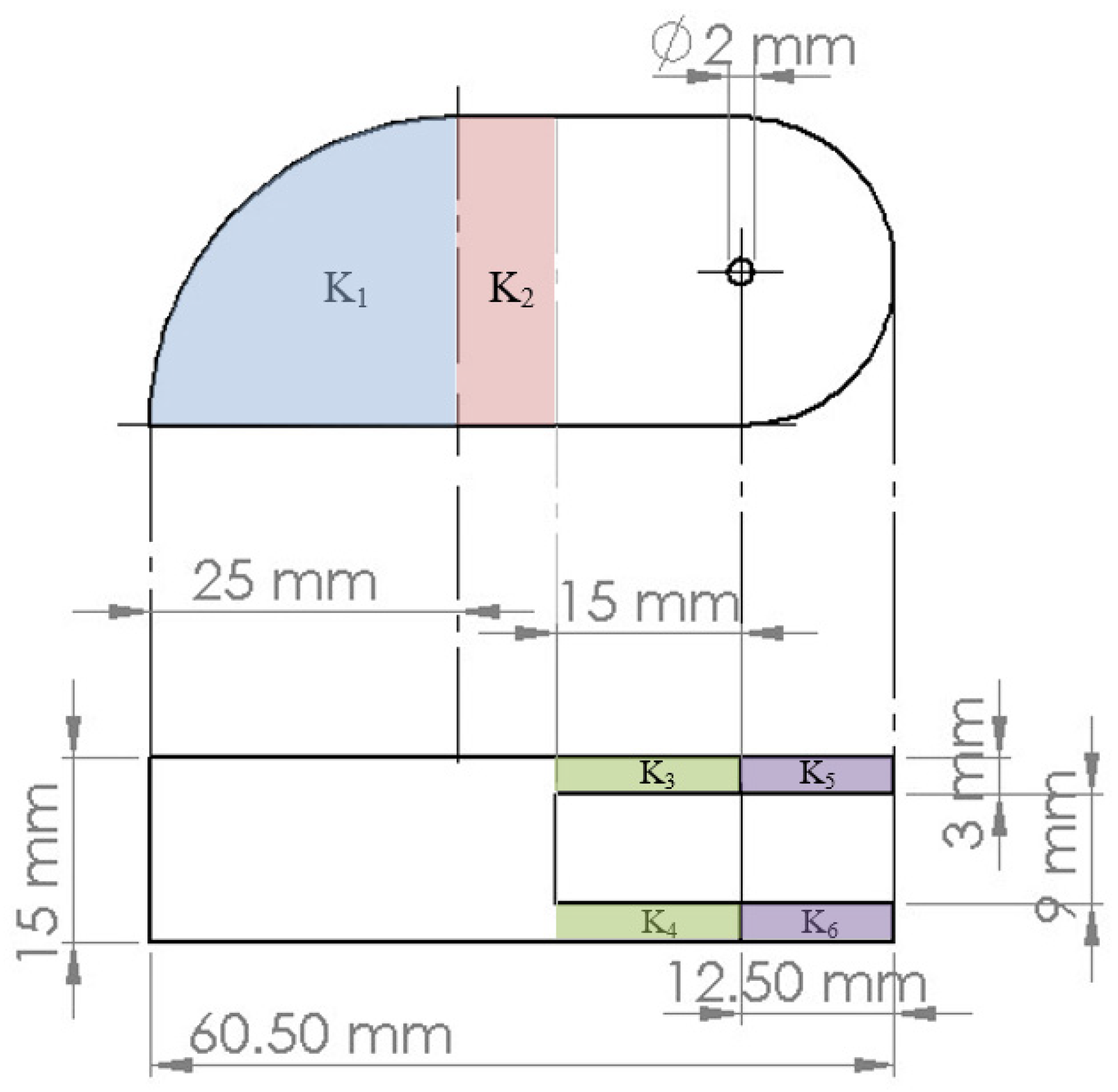
, it was treated as a composite body (i.e., consists of multiple segments). The moment of inertia for each segment labeled in
Figure 4 was calculated and then shifted using the parallel axis theorem to the axis of rotation of link
(which is
as shown in
Figure 2).
The link was made of acrylic, which had a density
= 1200 kg/m
3. The mass of each link equals:
The formula for the moment of inertia for is the same as for a cylinder (. However, this formula will give the moment of inertia with the center of the whole cylinder as the center of rotation. To correct this value, the parallel axis theorem will be used to move the axis to the centroid of the segment first, then to the center of rotation of link .
The centroid of a quarter of a circle is:
This can be used to calculate the distance between the center of the cylinder and the centroid
mm and approximate the distance between the centroid and the center of rotation
.
is a solid cuboid with its center moved from the center of rotation by
= 19 mm.
and
are solid cuboid with their center moved from the center of rotation by
= 7.5 mm.
and
can be treated as a cylinder whose axis of rotation is aligned with the center of rotation of the link:
The total moment of inertia of link
around its axis of rotation
is:
3.6. Control of Link L2
The first step in designing a controller for link is to relate the rotation (output) to the applied torque by the motor (input).
This relation can be obtained by using Newton’s second law:
By applying (21) around the axis of rotation of link
(i.e.,
):
where
is a rotational damping torque and has a damping coefficient
.
is the previously calculated mass moment of inertia of link
. By rearranging the above equation:
Substituting the given values:
Equation (23) is the differential equation relating the angle and the torque.
To build a transfer function from (23), Laplace transform is to be obtained with zero initial conditions (i.e.,
):
By rearranging (24) we get:
A Simulink model was built to simulate the control for link
Figure 5.
To simulate the action of the servo motor, a transfer function that represents its input/output characteristics is needed. Obtaining the transfer function of motors is often done experimentally, as the analytical method requires many details about the motor that might not be available, therefore, for the purpose of the simulation, a first-order transfer function for the motor was assumed:
The transfer function of the motor (26) is implemented in the yellow block in the model (
Figure 5), it receives its input (the control signal) from the PID controller block, its output is driving the transfer function for link
.
The blue block in the model is the transfer function for link (25), its output is the rotation of the link in radians.
The control loop was closed in this design using a camera, that is, a camera would sense the position of the link and generate a feedback signal. A model for the camera measurement was not included in this simulation, it was assumed that the camera, using some image processing technique, will measure the position of the tips accurately.
This feedback signal was compared with the setpoint to generate the error signal, which drives the PID controller.
For the selection and tuning of the PID parameters
, MATLAB PID tuner app was used. The parameters suggested by the application required some manual fine-tuning in order to get a near-perfect response. The final values are:
. These values are used in the PID block in the model
Figure 5.
3.7. Controller Stability
Stability analysis is an important part of control design; it ensures that the controller meets the performance requirements and is capable of sustaining reasonable modeling inaccuracies. While many advanced stability analysis methods are present in the literature [
26,
27,
28], the standard stability approach was employed here due to the simplicity of the controller and the design. The stability of the system can be addressed by deriving the closed-loop transfer function using equation (27) after multiplying the transfer functions of the PID controller, the actuator, and the motor; and assuming unity feedback loop,
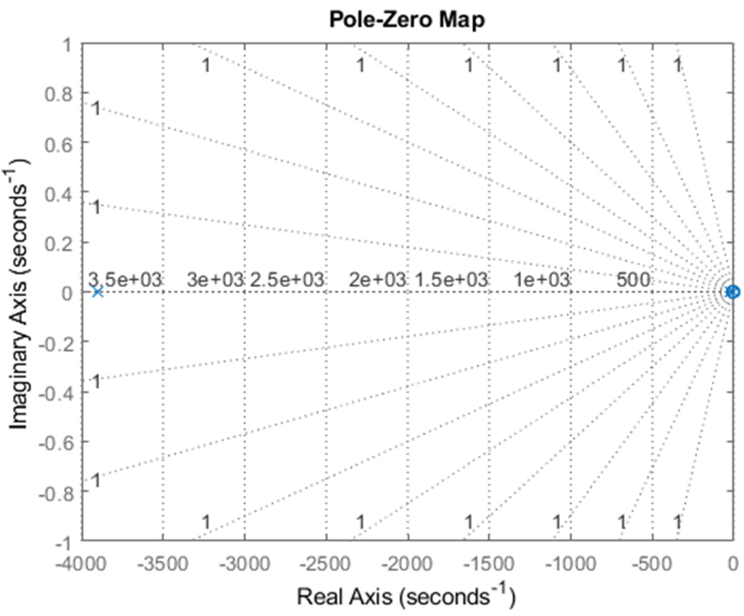
Figure 6 shows the poles and zeros of the control system. Since all of them are located on the left side of the imaginary axis, the system is said to be stable. The zero close to the origin does not affect stability, only the magnitude of the system response.
Figure 7 shows the root locus of those poles and zeros. Finally,
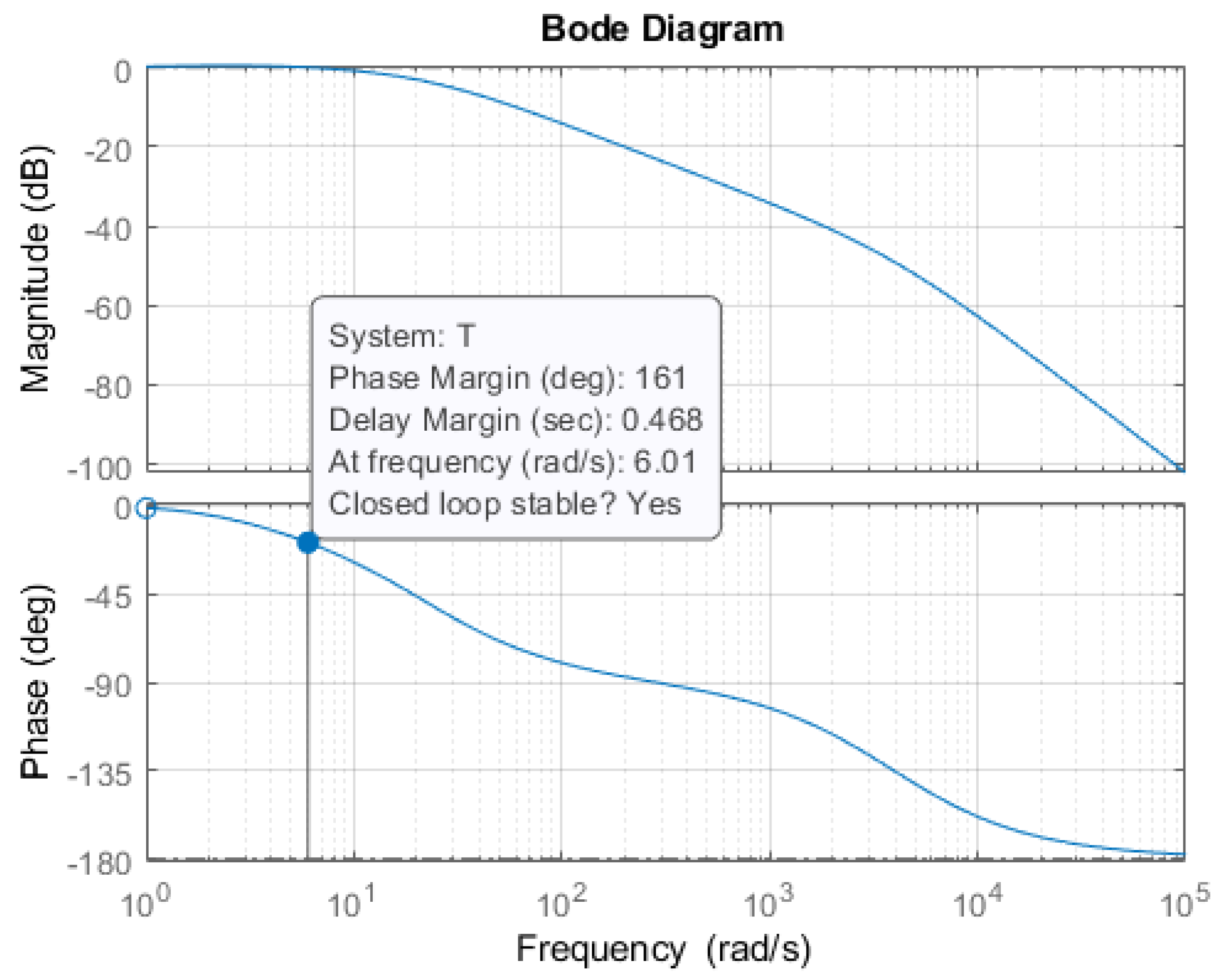
Figure 8 is the bode plot of the closed-loop control system. The gain margin of the system is said to be virtually infinite, which is a result of second-order transfer function approximation. The phase margin is
, which indicates a stable system.
5. Conclusions
A three-fingered subsea gripper module design was presented here. Starting with the mechanical design of the module and the fingers. Then, a forward kinematic matrix that can be applied for any of the three fingers was derived and used to plot the workspace. Force analysis was performed. Finally, the moment of inertia and torque control for the second link were discussed.
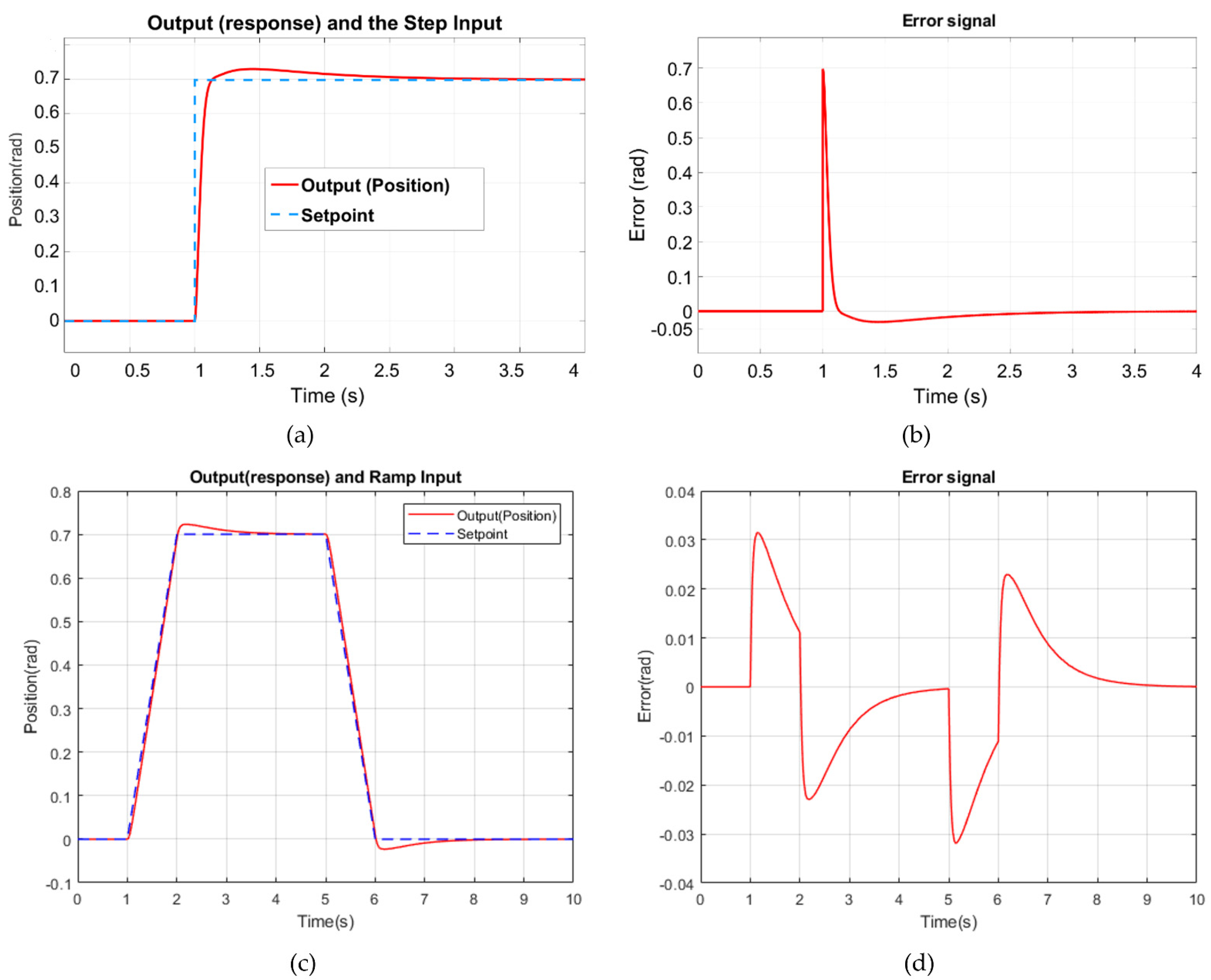
The performance of the controller can be concluded from
Figure 9a,b. The response is quick, the overshoot is minimum, and the steady-state error settles at zero.
However, the overall performance of this gripper module is highly dependent on the stability of the ROV itself. The ROV has to float steadily above the object to allow the camera to get proper coordinates and the gripper to grasp the object.
The total mass of the module was estimated to be 1.1 kg which is 40% of the mass of the ROV that will carry it. This might draw a challenge for the ROV to maintain its performance and stability and keep up with the new power requirement caused by the extra weight. The estimated cost is acceptable; it is about 30% of the cost of the OpenROV which is reasonable for an enhancement module that adds a new functionality of the ROV.
