Abstract
Subsoiling can break the compacted hardpan without turning or mixing soil layers. It has significant advantages in improving soil structure, promoting rainwater infiltration, and increasing air permeability of soil. The soil compacted hardpan will not be completely broken and more power consumption will be generated unless the desired tillage depth is obtained. However, due to uneven surface between and within each row of subsoiling shovel in the field, the existing adjustment methods, adjusting via the lifting device of the whole machine or a group of tillage components, cannot ensure each subsoiling shovel avoiding undesired tillage depth. Therefore, a tillage depth monitoring and control system for the independent adjustment of each subsoiling shovel was developed, and the methods of detecting, adjusting, displaying, and recording tillage depth were described. Field experiments were conducted to evaluate detecting accuracy, stability of tillage depth, transient response time, and advantages. The results showed that the value obtained by sensor differed from manual measurement at the speed of 3 km/h, 4 km/h, and 5 km/h averagely by 8.28%. The mean value of the coefficient of the tillage depth stability at three speeds were all greater than 94%. The mean transient response time was 0.6 s. The standard deviation of tillage depth obtained under system control was 38.31, which was less than the 51.52 obtained by only adjusting on the three-point suspension. The subsoiler equipped with this system was capable of obtaining a desired tillage depth of each subsoiling shovel in every second.
1. Introduction
As the substrate of root-system development, soil provides nutrients, water, and air needed for the crop growth [1]. Soil suitable for crop growth has desired bulk density, total porosity, and hardness, which are important indexes affecting soil permeability as well as significant indicators evaluating tillage quality [2,3,4]. Small bulk density indicates that soil has large porosity, good aeration, and permeability, which are beneficial to the absorption and utilization of water and nutrients by crop roots [5]. However, because of rainfall impact, freeze–thaw, and sedimentation under long-term conventional tillage, soil bulk density and hardness are increased while porosity is decreased [6]. Moreover, soil-compacted hardpan has been further formed, which restrains root propagation, inhibits root penetration, and reduces physiological activity, resulting in impaired root function and loss of nutrients and water absorption, and thus leading to a decline in yield [7,8,9].
Subsoiling tillage is capable of loosening soil and breaking the compacted hardpan without turning or mixing soil layers, which are able to reduce bulk density and hardness and increase porosity and permeability [10,11,12,13]. Thanks to these obtained effects, this technology is beneficial for soil-structure improvement, water storage and conservation, and root elongation into deeper soil [14]. Desired bulk density can be obtained by subsoiling, and the bulk density shows a downward trend with the increase of subsoiling depth [15]. Benefiting from the increase of soil porosity after subsoiling, the capacity of water storage of soil is enhanced, which reduces the amount of irrigation every day [16,17]. Compared with the conventional tillage, the roots are longer and heavier in deeper soil with better permeability in both horizontal and vertical directions after subsoiling, which significantly increases the average density of root length by 13% [18]. Moreover, the physiological activity of roots is improved by subsoiling, which is mainly manifested in reducing the peroxidation degree of cell membranes and delaying the senescence of roots, and thus contributing to higher crop yields [5].
The tillage depth is a significant index affecting the subsoiling quality and energy efficiency [19], while it is also an important consideration basis for the government to conduct subsoiling subsidies in China. During subsoiling operation, the soil-compacted hardpan cannot be broken completely with insufficient depth, and thus the poor quality of the soil properties’ improvement is obtained. Meanwhile, power consumption and operation cost are increased with excessive depth, resulting in the reduction of energy efficiency. Currently, the tillage depth is mainly measured manually at selected points in the subsoiled row in China. This method is incapable of obtaining the data of continuous tillage depth changing with time and it has high labor intensity and low work efficiency; especially the measurement accuracy of it is greatly affected by human factors, so it has large measurement errors [20]. Meanwhile, the adjustment of the subsoiling depth mainly depends on the working experience of the driver, so it is impossible to accurately and timely adjust the depth to the required tillage depth. Therefore, it is of prime importance to develop the on-line tillage depth detection and control method to obtain desired tillage depth of subsoiling machines.
Subsoiling machines are divided into vibrating subsoiling machines and non-vibrating subsoiling machines. Furthermore, according to whether the excitation source requires a power drive or not, the vibration mode can be divided into forced vibration and self-excited vibration. These two kinds of vibrating subsoiling methods are unfavorable to the detection of tillage depth due to the strong vibration, and there is interference between vibration and tillage depth control [21,22,23,24]. A non-vibrating subsoiling machine mainly includes the omni-directional subsoiling machine and chisel subsoiling machine. The omni-directional subsoiling machine is capable of cutting the soil into strips with trapezoidal sections, performing better in breaking soil. However, tillage depth adjustment will make the blockage more serious in the stubble field caused by the smaller spacing between adjacent shovels [25,26]. While adjacent shovels of the chisel subsoiling machine are arranged laterally with intervals’ sizing from 40 cm to 80 cm, this kind of subsoiling machine works with smaller tillage depth and width and requires less power [27,28], which is adaptive for equipping with tillage depth monitoring and control system.
The sensor detection combined with hydraulic or electromechanical adjustment is an important method for on-line detection and control of tillage depth. At present, there are two types of sensors that are mainly used to obtain tillage depth: one for angle measurement and the other for distance measurement. The sensors for measuring the angle mainly include the inclination sensor, potentiometer, and rotary encoder, which are installed on the lift arm of the tractor to detect dip angle from the horizontal plane [29,30,31,32]. By substituting the measured value into the mathematical formula of the angle and depth, the tillage depth can be obtained. Furthermore, the lift arm of the tractor was adjusted by the hydraulic system to change the tillage depth of the whole machine [31]. In addition, the tillage depth of the individual tillage component can be obtained by installing this type of sensor on the linking arm, which was used to connect the gauge wheel and the frame to measure the rotation angle of the gauge wheel relative to the frame [33,34]. Additionally, the sensors for measuring distance include the ultrasonic sensor and laser range sensor, which are installed at the bottom of the horizontal frame to detect the distance between the frame and the surface. Because the distance between the shovel tip of the subsoiling shovel and the bottom of the frame is invariant, tillage depth can be obtained by subtracting the detection value from the invariant value [35,36,37]. Additionally, this method has been proven to have better measuring accuracy [38]. Furthermore, the undesired tillage depth is adjusted to the required value by hydraulic adjustment or electromechanical control [39]. In addition, there is also a method of measuring distance and angle simultaneously to get the tillage depth [40].
Apart from above research works, some agricultural machinery enterprises, such as Topcon, John Deere, and CASE, have developed tillage depth monitoring and control systems, applying them on tillage machineries. The NORAC tillage depth detection system is designed by Topcon, which depends on four ultrasonic sensors to respectively detect the tillage depth of four disc gangs [41]. Its characteristic is that it is capable of adjusting the tillage depth of each disc gang independently according to the surface changes. The TruSet monitoring system and AccuDpthTM hydraulic system and the AFS (Advanced Farming System) tillage depth intelligent monitoring system and the supporting hydraulic system have been respectively developed by John Deere and CASE [42,43]. These monitoring and control systems are capable of accurately detecting tillage depth and precisely adjusting the tillage depth to the required value. Meanwhile, algorithm optimization and response surface optimization are capable of further improving the performance of the control system [44,45]. All the above studies are aimed at adjusting the tillage depth of the whole machine or a group of tillage components of the combined scarification equipment. However, due to uneven surfaces between and within each row of subsoiling shovel in the field, the current methods cannot ensure each subsoiling shovel avoiding undesired tillage depth, leading to soil-compacted hardpan of some rows incompletely broken or increased power consumption and operation cost. Therefore, it is necessary to develop the tillage depth monitoring and control system for the independent adjustment of each subsoiling shovel to obtain the desired tillage depth of each row. Some tillage depth detection and control methods around the world are discussed in Table 1.

Table 1.
Comparison of different kinds of tillage depth detection and control methods.
In this paper, we provide a design of the tillage depth monitoring and control system for the subsoiler with subsoiling assemblies to ensure each subsoiling shovel avoiding undesired tillage depth and to improve tillage depth stability of each row. The tillage depth of each subsoiling shovel was obtained by an ultrasonic sensor and adjusted by the hydraulic system. Meanwhile, the tillage depth data were displayed via an interactive touch screen and recorded in a timely manner in a mobile hard disk. The performance of the tillage depth monitoring and control system was evaluated by the detecting accuracy, stability of tillage depth, transient response time, and advantages.
2. Materials and Methods
2.1. Description of the Single Subsoiling Assembly
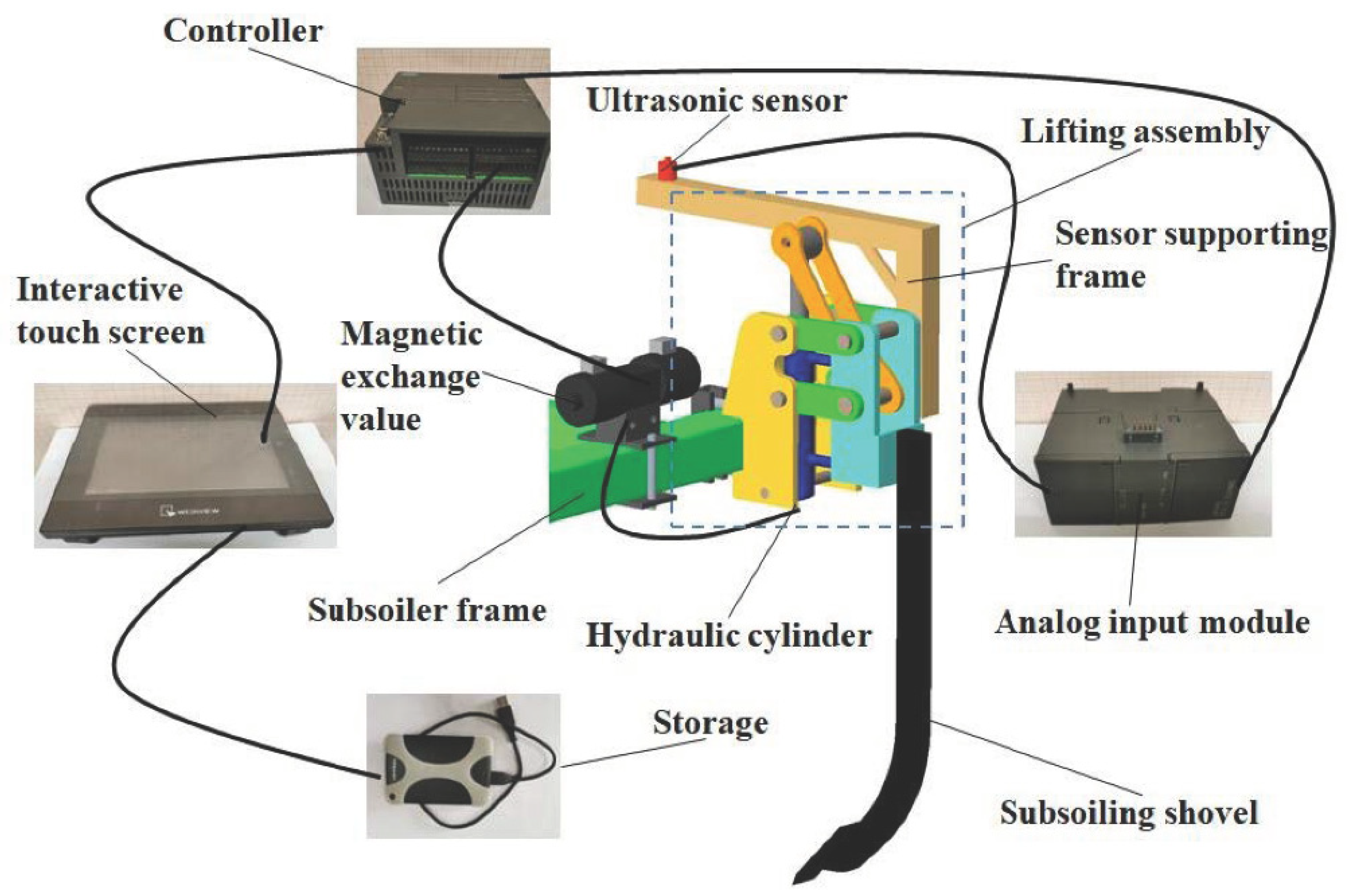
The single subsoiling assembly is composed of a lifting assembly, a supporting frame of the ultrasonic sensor, and a subsoiling shovel, which is capable of independently adjusting the tillage depth of a single row and was selected for this study. Its structure is shown in Figure 1. The lifting assembly is fixed on the subsoiler frame, and the sensor-supporting frame and the subsoiling shovel are respectively mounted on one side of it. The elongation or shortening of the hydraulic cylinder is converted into the vertical movement of the subsoiling shovel through the four-bar linkage and the hydraulic link mechanism, so as to adjust the tillage depth. The structure parameters were as follows: The subsoiling shovel used in this study had a curved handle with a vertical height of Hh = 800 mm, of which the suitable tillage depth ranged from 250 mm to 450 mm; the width of the shovel tip was Lw = 40 mm and the length was Ll = 155 mm; the diameter and rod diameter of the hydraulic cylinder, respectively, were Dh = 32 mm and Dr = 20 mm; the stroke of hydraulic cylinder was S = 200 mm; the length of the horizontal section of the support frame was Lh = 700 mm; the vertical height between the horizontal plane of the support frame and the bottom of the shovel tip was L = 1150 mm.

Figure 1.
The single subsoiling assembly equipped with the tillage depth monitoring and control system.
2.2. Design of the Tillage Depth Monitoring and Control System
2.2.1. Tillage Depth MONITORING and Control System
The tillage depth monitoring and control system was designed for the subsoiler with single subsoiling assemblies, which were capable of independently detecting, displaying, recording, and adjusting the tillage depth of each subsoiling shovel at the same time. The monitoring and control system consisted of ultrasonic sensors (NU175F30TR-I-2000, China), an analog input module (S7-200SMART EM AI04, SIEMENS, Nanjing, China), a programmable logic controller (S7-200SMART, CPU ST40, SIEMENS, Nanjing, China), an interactive touch screen (MT6071iP, WEINVIEW, Beijing, China), magnetic exchange values (DSG-03-3C60-DL-DC24, YOUYAN, Wuxi, China), and a storage, as shown in Figure 1. The ultrasonic sensor used in this study was a three-wire system sensor. Its performance parameters were as follows: The measuring range was 100~2000 mm with an accuracy of 0.1 mm; the output signal was an analog signal from 4 mA to 20 mA; and the working voltage and temperature, respectively, were 10~30 VDC and −20 °C~+60 °C. The analog input module had four groups of positive and negative input addresses and the PLC had 40 I/O points. The magnetic exchange value with three positions and four ways was used in this study, which was able to control the hydraulic cylinder lengthening, shortening or unchanging. The on-board battery of the tractor, which was charged automatically during field operation, provided a 24-V power supply for the tillage depth monitoring and system.
The block diagram of the tillage depth monitoring and control system is shown in Figure 2. The analog signal output by an ultrasonic sensor was converted into digital value by the analog input module. Then, it was analyzed, processed, and output by the PLC to control the driving circuit of the left or right switch belonging to the magnetic exchange valve to complete the corresponding operation. Meanwhile, the tillage depth was displayed in a timely manner on the interface of the interactive touch screen, which communicated with the PLC via the RS485 serial port, and the tillage depth was recorded in a timely manner in the storage.
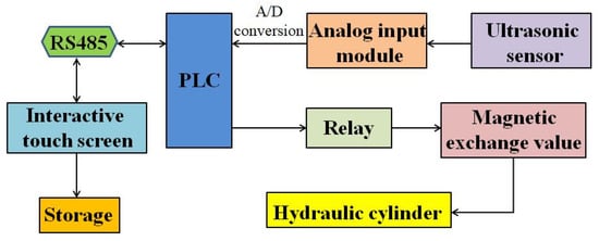
Figure 2.
Block diagram of the tillage depth monitoring and control system.
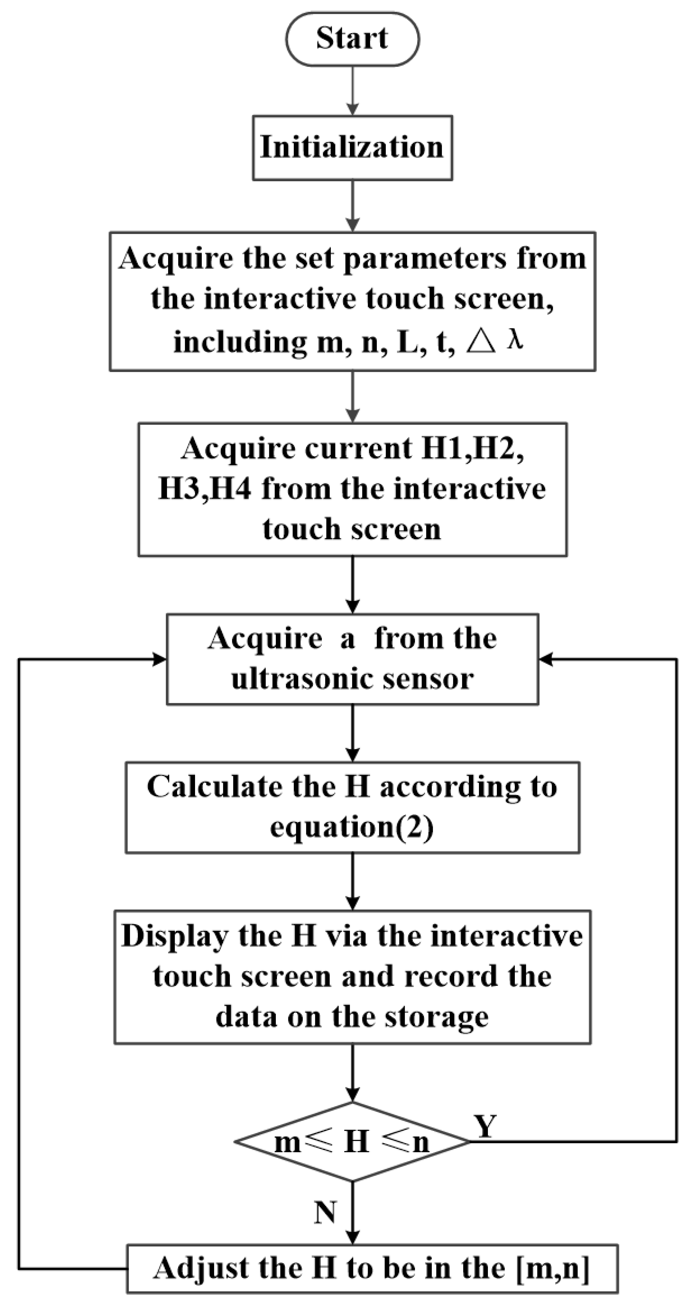
The flow chart of the main program is shown in Figure 3. After the tillage depth monitoring and control system was powered on, the values of set parameters could be entered on the interactive touch screen, including the minimum set value of tillage depth (m), the maximum set value of tillage depth (n), the vertical height between the signal transmitting end (receiving end) of the ultrasonic sensor and the bottom of the shovel tip (L), the system error (Δλ), and the delay time (t), which were all displayed on the interface of the interactive touch screen. Meanwhile, the current tillage depth of each subsoiling shovel, obtained by the sensor detection and controller process, was also displayed on the interface of the interactive touch screen. During the subsoiling operation, the ultrasonic sensor was used to detect the vertical height between the signal transmitting end (receiving end) and the field surface, which was represented by a. The analog quantity output by the ultrasonic sensor was converted into the physical quantity representing the distance by two conversions. Then, it was analyzed and processed by the controller according to the program written by the established mathematical model of tillage depth; thus, the current tillage depth of each subsoiling shovel, represented by H, was obtained and displayed on the interface of the interactive touch screen. If the current tillage depth was less than the minimum set value, the drive circuit of the left value belonging to the magnetic exchange valve would be controlled to be connected, and, thus, the hydraulic oil circuit corresponding to the left value would be opened to make the hydraulic cylinder shortened, so as to adjust the tillage depth increasing to be within the set range. If the current tillage depth was more than the maximum set value, the drive circuit of the right value belonging to the magnetic exchange valve would be controlled to be connected, and, thus, the hydraulic oil circuit corresponding to the right value would be opened to make the hydraulic cylinder lengthened, so as to adjust the tillage depth decreasing to be within the set range. If the current tillage depth was within the set range, the magnetic exchange value would automatically remain in the neutral position, and, thus, the subsoiling shovel would not be adjusted. The tillage depth of each subsoiling shovel was detected, displayed, recorded, and adjusted by the tillage depth monitoring and control system at a period of 1 s.
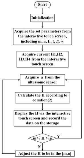
Figure 3.
The flow chart of the main program.
The response time of the tillage depth monitoring and control system included the sample time of the ultrasonic sensor, the execution time of the PLC, the response time of the intermediate relay and magnetic exchange value, and the performing time of the hydraulic cylinder. Because sensor sampling and PLC execution were completed within the scanning period of the control system, which was 2 ms, these times could be negligible to analyze the response time of the control system. As obtained in Section 3.3, the speed of the hydraulic cylinder was 0.54 m/s and the response time of the control system was 0.46 s. The forward speed of the tractor generally was 3~5 km/h. Thus, the advance distance of the subsoiling shovel within the response time of the control system ranged from 380 mm to 640 mm, which was less than the horizontal distance between the subsoiling shovel and the ultrasonic sensor that was described in Section 2.1. Thus, the delay time was given by the Equation (1).
where t is the delay time, L0 is the horizontal distance between the subsoiling shovel and the ultrasonic sensor, v is the forward speed of the tractor, and t1 is the response time of the control system.
2.2.2. Tillage Depth Detecting by Ultrasonic Sensor
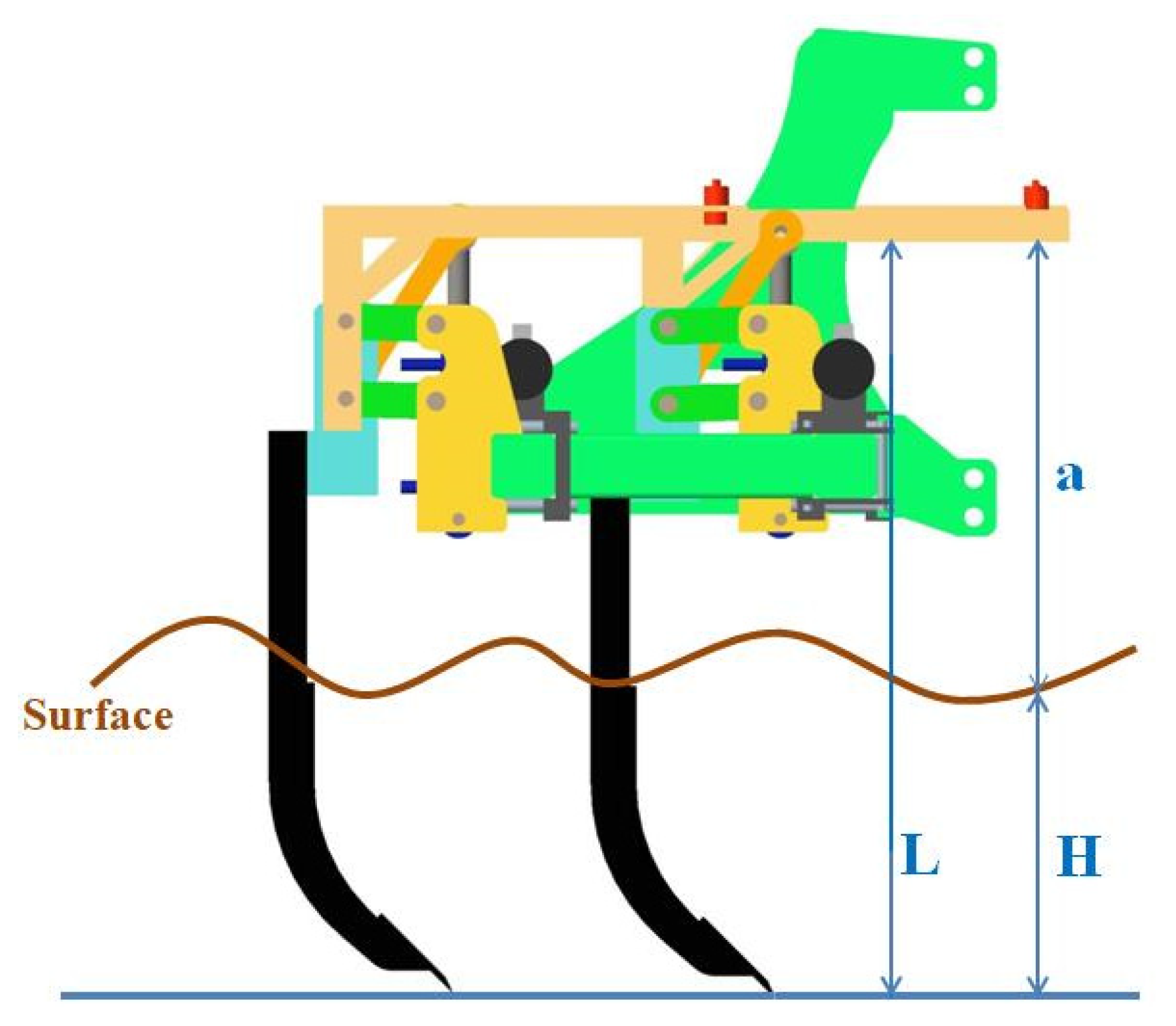
The ultrasonic sensor applied in this study was used to detect the vertical height between the signal transmitting end (receiving end) of the ultrasonic sensor and the field surface, which was installed on one side of the horizontal section of the sensor-supporting frame and was located in front of the subsoiling shovel along the forward direction of the subsoiler. It was described in Section 2.1 that the distance between the sensor-mounted position and the other end of the horizontal section of the sensor-supporting frame was 500 mm. As shown in Figure 1, the sensor-supporting frame and the subsoiling shovel were fixed on the same component in a single subsoiling assembly, so the vertical movement of the subsoiling shovel and the sensor-supporting frame was synchronous. More specifically, the elongation or shortening of the hydraulic cylinder was converted into the vertical upward or downward movement of the subsoiling shovel and sensor-supporting frame through the four-bar linkage and the hydraulic link mechanism during the tillage depth adjustment. Therefore, the vertical height between the horizontal plane of the sensor-supporting frame and the bottom of the shovel tip remained unchanged. Thus, given the vertical height between the signal transmitting end (receiving end) of the ultrasonic sensor and the field surface, and the vertical height between the horizontal plane of the sensor-supporting frame and the bottom of the shovel tip, the tillage depth at a certain distance in front of the subsoiling shovel could be calculated. The method for detecting tillage depth by the ultrasonic sensor used in this study was a method for detecting surface changes in front of the subsoiling shovel. Based on the output signal of the ultrasonic sensor, the tillage depth adjustment of the subsoiling shovel was controlled by the monitoring and control system. This method avoided the problem of a large distance between points of tillage depth detection and tillage depth adjustment caused by profiling lag. The schematic diagram of the detection method is shown in Figure 4, and the tillage depth was given by the Equation (2).
where H is the tillage depth, L is the vertical height between the horizontal plane of the sensor-supporting frame and the bottom of the shovel tip a is the vertical height between the signal transmitting end (receiving end) of the ultrasonic sensor and the field surface measured by ultrasonic sensor, and Δλ is the system error.

Figure 4.
The method for detecting tillage depth.
In order to present the analog quantity output by the ultrasonic sensor in the form of a physical quantity representing the tillage depth displayed via the interactive touch screen and stored in the storage, two conversions were adopted to convert the analog quantity into the physical quantity in this study. Firstly, the analog quantity output by the ultrasonic sensor was converted into the digital quantity by the analog input module, and then the digital quantity was converted into the physical quantity by the signal conversion program. Finally, the physical quantity representing the distance measured by the ultrasonic sensor was analyzed and processed by the controller according to Equation (2) to obtain the current tillage depth, which was displayed via the interactive touch screen and stored in the storage.
The linear relation between the digital quantity and the physical quantity was:
where Z is the real-time digital quantity, X is the real-time physical quantity, and , respectively, represent the minimum value and maximum value of the digital quantity converted from the analog signal output by the ultrasonic sensor, and and , respectively, represent the minimum value and maximum value of the physical quantity corresponding to the analog signal output by the ultrasonic sensor.
As described in Section 2.2.1, the analog signal output by the ultrasonic sensor used in this study ranged from 4 mA to 20 mA. Converting the analog quantity into the digital quantity, the obtained digital quantity ranged from 0 to 27,648 [46]. The measuring range of the ultrasonic sensor was 100~2000 mm. Substituting the corresponding values into the Equations (3) and (4) we obtained:
Therefore, the signal conversion program could be established according to the Equation (4) [47]. Thus, the analog quantity output by the ultrasonic sensor was presented in the form of the physical quantity representing the measured distance between the signal transmitting end (receiving end) of the ultrasonic sensor and the field surface.
The nonlinearity and sensitivity of the sensor are important indexes that should be taken into consideration to determine whether the performance of the sensor meets the requirement in this study. The nonlinearity represents the deviation degree between the calibration curve and the fitting line, of which the smaller the value is, the better the linear characteristics of the sensor are. The sensitivity is the ratio of output increment to input increment. The nonlinearity and sensitivity S are respectively given by Equations (5) and (6).
where is the maximum deviation between the calibration curve and the fitting line, is the full-span output range, and and respectively represent the output increment and input increment.
The nonlinearity and sensitivity of the ultrasonic sensor used in this study were evaluated by the preliminary test and statistical analysis. The test was conducted in the Conservation Tillage Research Centre, MOA, of China. The ultrasonic sensor was lifted vertically and its signal transmitter, also the receiver, was positioned successively at 100 heights from the ground, which were determined by manual measurement. These 100 height values formed an arithmetic sequence with a tolerance of 19 mm from 100 mm to 2000 mm. The signal output by the ultrasonic sensor was processed by the PLC and, finally, the corresponding digital quantity (0~27,648) was displayed via the interactive touch screen. Regression analysis was conducted using statistical software (IBM SPSS Statistics 25, IBM, New York, NY, USA) on the relationship between the measured height and the corresponding digital quantity. The results showed that the nonlinearity and average sensitivity of the ultrasonic sensor, respectively, were and 14.554, which indicated that the ultrasonic sensor was reliable in detecting surface changes and was capable of outputting the correct signal even for small surface changes. Therefore, this type of ultrasonic sensor was selected to be applied to the tillage depth monitoring and control system in this study.
2.2.3. Tillage Depth Displaying via Interactive Touch Screen
Human computer interface is the medium of interaction and information exchange between system and users. In this study, the human–computer interactive touch screen was used to enter values of set parameters and display tillage depth of each subsoiling shovel in a timely manner. As described in Section 2.2.1, the human–computer interactive touch screen (MT6071iP) was selected to be applied to the tillage depth monitoring and control system, which communicated with the PLC via RS485 serial port. Before subsoiling operation, values of set parameters were entered on the interface, including L, Δλ, t, m, and n. To be specific, L was the vertical height between the horizontal plane of the sensor-supporting frame and the bottom of the shovel tip, Δλ was the system error, t was the delay time, and m and n, respectively, were the minimum and maximum set values of tillage depth. During subsoiling operation, the signal output by each ultrasonic sensor was firstly converted into the physical quantity representing the distance, and then the tillage depth of each subsoiling shovel was obtained through the analysis and process of the PLC. Finally, the tillage depth of each subsoiling shovel was displayed on the interface through the communication of the interactive touch screen with the PLC via RS485 serial port. The program design of the interactive interface was completed via the configuration software (EasyBuilder Pro, Beijing, China).
2.3. Evaluation Experiments
2.3.1. Test Arrangement
To ensure the detecting accuracy, each ultrasonic sensor was the key to obtaining the desired tillage depth of each subsoiling shovel. Therefore, a test was conducted to compare tillage depth obtained by sensor detection and manual measurement. The minimum set value of tillage depth was 320 mm and the maximum set value of tillage depth was 450 mm, which were entered via the interface of the interactive touch screen. From the start to the stop of the system, the forward time of the subsoiler was 55 s at the speed of 3 km/h, 4 km/h, and 5 km/h, respectively. When the operation was finished at the current speed, the subsoiler was powered by the tractor turned around, and then changing the forward speed to start the operation again in the adjacent area. During subsoiling operation, the tillage depth of each subsoiling shovel was displayed and recorded in a cycle of 1 s. After the subsoiling operation, the tillage depth of points selected equidistant were measured manually, referring to China Machinery Standard NT/T 2845-2015 [48]. The distance between two selected contiguous points was equal to the product of the forward speed and 1 s; thus, this value corresponding to 3 km/h was 0.8 m, corresponding to 4 km/h was 1.1 m, and corresponding to 5 km/h was 1.4 m. Twenty points with the same interval within 10~30 s of the forward time were selected for manual measurement in each subsoiled row, and a total of 12 rows of tillage depth were measured. Comparing and analyzing tillage depth obtained by the sensors with that measured manually we evaluated the accuracy of detecting tillage depth by sensors.
The coefficient of tillage depth stability is an important index to evaluate the subsoiling quality. Adding the variation coefficient of tillage depth to this value was equal to 1, and the calculation of the variation coefficient of tillage depth was the premise to obtain the coefficient of tillage depth stability. The smaller the variation coefficient of tillage depth is, the more the actual tillage depth is consistent with the set tillage depth. Along each route subsoiled by the subsoiler at three speeds in the above test to evaluate accuracy of detecting the tillage depth by sensors, a total of 20 points in one row with an interval of 1 m was selected to measure the tillage depth manually within the forward distance of 10~30 m away from the starting position. The variation coefficient of tillage depth was derived by the Equations (7)–(9), and the coefficient of tillage depth stability was given by Equation (10).
where a is the average value of the tillage depth, is the tillage depth of each point by manual measurement, n is the number of measured points, S is the standard deviation of tillage depth, V is the variation coefficient of tillage depth, and U is the coefficient of tillage depth stability.
The transient response time represents the time required for the system to reach a new stable state. In this study, this response characteristic indicated when the subsoiling depth changed out of the set range, and the time taken by the monitoring and control system from the beginning of adjusting tillage depth until the tillage depth was adjusted to the set range and remained almost constant. The monitoring and control system took 1 s as a cycle to detect, display, record tillage depth, and adjust undesired tillage depth to be within the set range. Therefore, a test was conducted to determine the transient response time, and, thus, to evaluate the output response performance of the control system and further verify whether the control system was able to control the tillage depth within the set range in 1 s when the actual subsoiling depth was less than the minimum set value or greater than the maximum set value of tillage depth. A clean soil surface was obtained by removing straw in front of the first subsoiling shovel. By measuring and determining the height from the signal transmitting end (receiving end) of the ultrasonic sensor to the field surface with a tape, the tillage depth was adjusted to 100 mm and 600 mm successively to simulate tillage depth less than the minimum set value and greater than the maximum set value, respectively. The minimum set value was 250 mm while the maximum set value was 450 mm, which were entered on the interface of the interactive touch screen. The test program and the response time was written and timed by the Step7-Microwin SMART software, and the PLC was also used for synchronously timing.
To evaluate the effectiveness of the monitoring and control system in improving the stability of tillage depth of a single subsoiling shovel and to demonstrate whether it was advantageous to apply this system to obtain desired tillage depth, a comparative test was carried out between independent adjustment of a single row and unified adjustment of each row. During the subsoiling operation, the independent adjustment of a single row was accomplished under the running state of the tillage depth monitoring and control system, while the unified adjustment of each row was accomplished by only adjusting on the three-point suspension without running system. The tillage depth was set from 250 mm to 450 mm via the interface of the interactive touch screen, and the operation distance was 50 m at the forward speed of 5 km/h under running state and non-running state of the monitoring and control system, respectively. Manual measurement of the tillage depth was conducted at selected points along the subsoiled route of the second subsoiling shovel. The first point was 16 m away from the starting position, and 10 points were selected to be measured manually, of which the interval between each two points was 2 m.
Apart from the above test arrangements, to evaluate whether the stability of tillage depth of the subsoiling shovel with tillage depth adjustment was better than that without tillage depth adjustment, the fourth subsoiling assembly was set as the control group without adjustment, of which the tillage depth was only detected, displayed, and recorded throughout the experiments. The first subsoiling assembly, the second subsoiling assembly, and the third subsoiling assembly were equipped with the complete monitoring and control system, which was capable of detecting, displaying, recording, and adjusting tillage depth throughout the experiments. As shown in Figure 5, the subsoiler with four subsoiling assemblies was powered by the Levo TG series M1254-G tractor to conduct experiments.
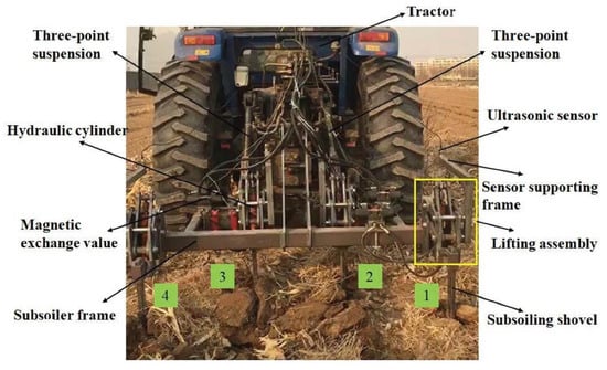
Figure 5.
Components of the subsoiler equipped with the tillage depth monitoring and control system in the field experiments.
2.3.2. Test Conditions
Evaluation experiments were conducted in Shijiazhuang, Shenze county (, ), situated in central and southern Hebei province, North China. Shenze is located in a warm and semi-humid region and has a continental monsoon climate. The average amount of sunshine is 7.4 h per day. The average annual temperature is 12.4 °C with 188 frost-free days. The average annual rainfall is 489.8 mm and 54% of the rainfall occurs during July–August. The soils are defined as loam according to international soil classification systems (USDA, AASHTO). The average soil moisture content is 15.4% and the average soil bulk density is . The surface of the field is uneven, and the difference in height between the upper and lower surface ranges from 10 cm to 20 cm. After the maize harvest, there is straw covering the field with stubble retention. The straw yield is about 3255 kg/ha and the stubble height ranges from 5 cm to 20 cm.
3. Results and Discussion
3.1. Accuracy in Detecting Tillage Depth
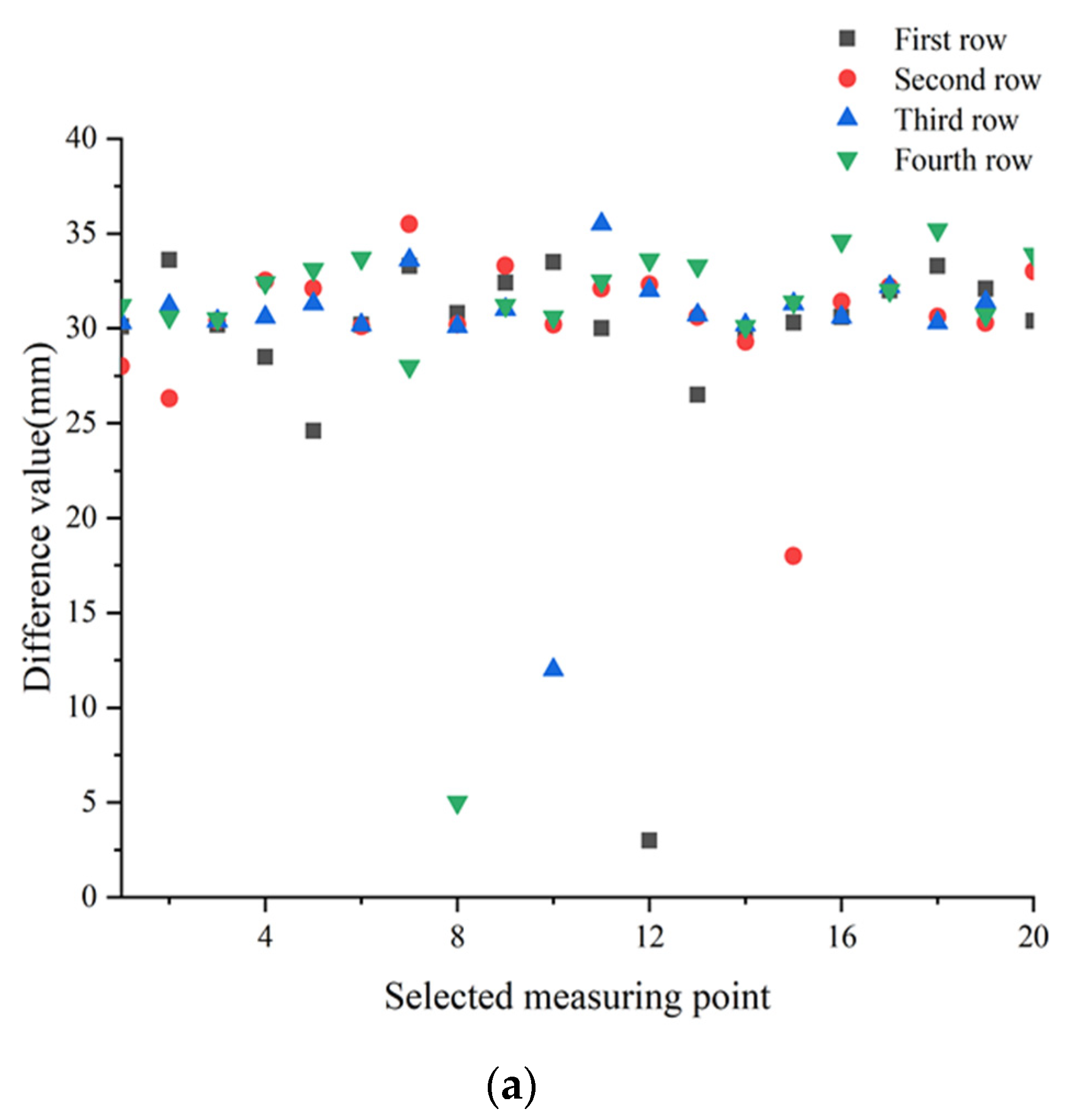
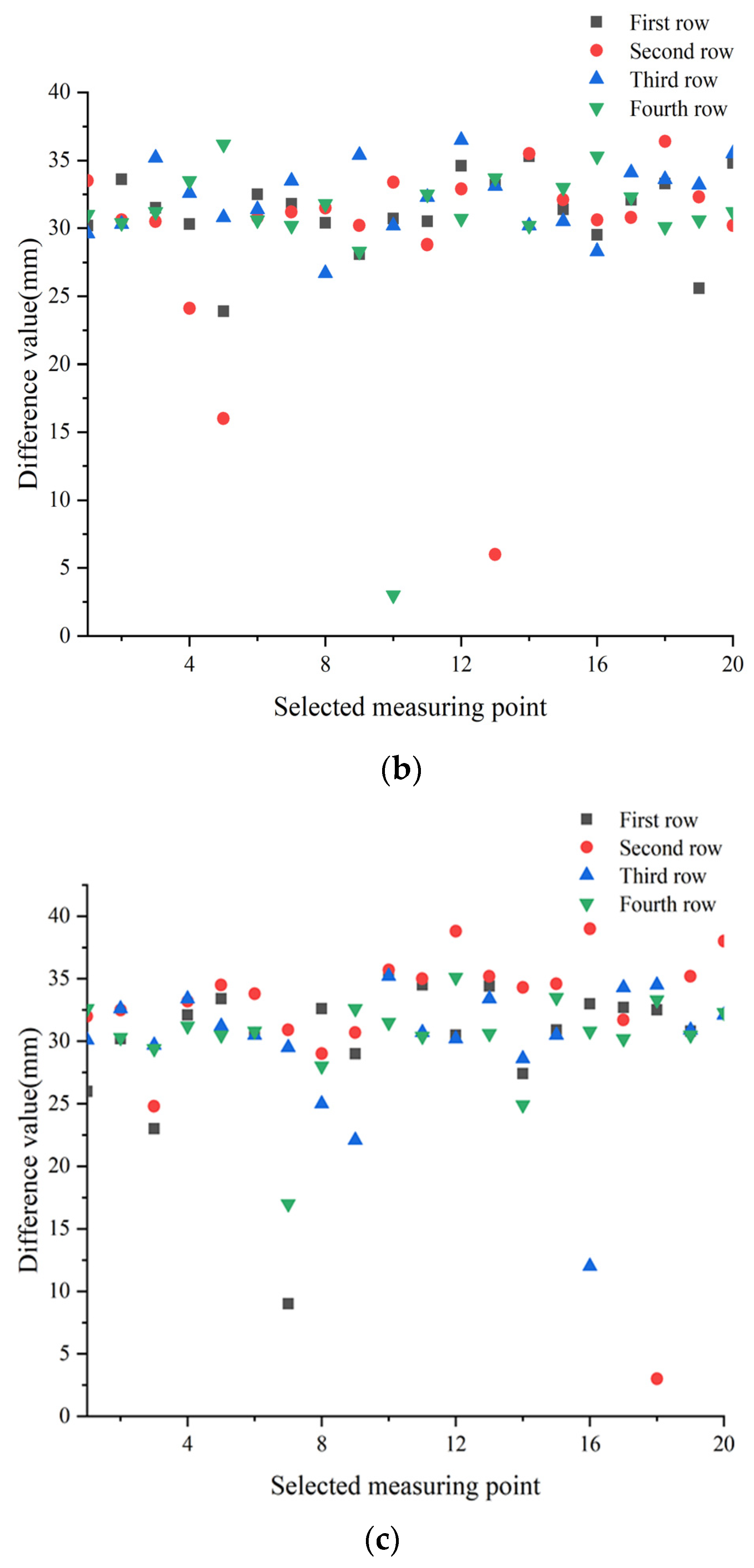
According to the soil conditions and tillage depths obtained by sensors and measured manually of 20 points in each row at three speeds, the data of two points were eliminated to get the difference value between the tillage depths obtained by these two methods at each remaining point (Figure 6), as well as the mean value of the tillage depths obtained by sensors and measured manually in each row at three speeds (Table 1). These two points included the fifth measurement point in the third row at the speed of 3 km/h, and the 14th measurement point in the first row at the speed of 5 km/h. The source of this was that the detection position of the ultrasonic sensor was in front of the subsoiling shovel. The tillage depth obtained by ultrasonic sensors at these two points was outside the set range, and, fortunately, they were adjusted in time by the control system. Therefore, the manual measurement values of these two points were all within the set range. Thus, the corresponding tillage depth data of these two points were eliminated.
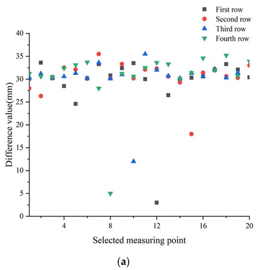
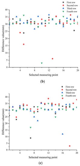
Figure 6.
Difference value between tillage depths obtained by sensors and measured manually at forward speeds of (a) 3.0 km/h, (b) 4.0 km/h, and (c) 5.0 km/h.
As shown in Figure 6, the tillage depth obtained by sensors was larger than that measured manually at any point at three speeds, with a maximum difference of 38.8 mm and a minimum difference of 3 mm. The difference value between the mean tillage depths obtained by sensors and that measured manually at all points in each row was about 30 mm, with a maximum difference of 32.15 mm and a minimum difference of 29.37 mm. Thus, the errors between sensor detection and manual measurement at the speed of 3 km/h, 4 km/h, and 5 km/h, respectively, was 8.35%, 8.1%, and 8.38% (Table 1), which were possibly caused when the acoustic wave sent by the ultrasonic sensor met the straw, generating the echo. However, there was a certain thickness between the soil surface and the straw surface that made the tillage depth obtained by sensors slightly greater than that measured manually. Yang et al. [49] stated that the accuracy of detecting the cutting-table height of the combine harvester by ultrasonic sensors was slightly influenced by the crops in the field. Mouazen et al. [35] also found that compared to the soil covered with straw, the ultrasonic sensor had higher detection accuracy in soft, sandy, loam soil. The manual measurement results illustrated that the tillage depths of each row operated by subsoiling assemblies equipped with the complete tillage depth monitoring and control system were all within the set range and the errors were acceptable. Therefore, the method of applying ultrasonic sensors to obtain the tillage depth was reliable.
3.2. Tillage Depth
The coefficients of the tillage depth stability at forward speeds of 3 km/h, 4 km/h, and 5 km/h are provided in Table 2. The coefficients of the tillage depth stability for each row at three speeds were all above 90% (Table 3). The mean value of the coefficient of the tillage depth stability of the first three rows at each speed, respectively, was 97.5%, 97.9%, and 94.9%, which were all far greater than 85%. Therefore, the subsoiler equipped with the monitoring and control system was proven to meet the standard requirement of subsoiling machines. While the coefficient of the tillage depth stability of the fourth row at three speeds, respectively, was 97.7%, 91.5%, and 97.4%. The coefficient of the tillage depth stability of the fourth row was much less than that of the other rows at the speed of 4 km/h. This was because there was a large bump on the surface belonging to the operation row of the fourth subsoiling shovel when the subsoiler advanced at the speed of 4 km/h. However, due to a lack of the function of tillage depth adjustment, the tillage depth changed greatly and the tillage depth stability became worse. Meanwhile, the actual tillage depth was far greater than the maximum set value, also leading to an increase in power consumption. By comparing the coefficients of the tillage depth stability at the speed of 4 km/h with those at the speed of 5 km/h, it showed that with the increase of the forward speed, the coefficient of the tillage depth stability decreased. This was similar to the relationship between the variation coefficient of tillage depth and the forward speed obtained by Wang [33], which showed that the variation coefficient of tillage depth became larger with the increase of the forward speed. Therefore, the coefficient of the tillage depth stability of the first row being less than that of other rows at the speed of 5 km/h was possibly caused by the increase of the forward speed and very uneven surface belonging to the operation row of the first subsoiling shovel at this speed. Thanks to the control system, the tillage depth of the first subsoiling shovel was adjusted to the set range in time, and, thus, the desired tillage depth was obtained and the stability of the tillage depth was ensured.
Table 2.
Mean tillage depths obtained at forward speeds of 3.0, 4.0, and 5.0 km/h.
Table 3.
Results of the coefficient of tillage depth stability at forward speeds of 3.0, 4.0, and 5.0 km/h.
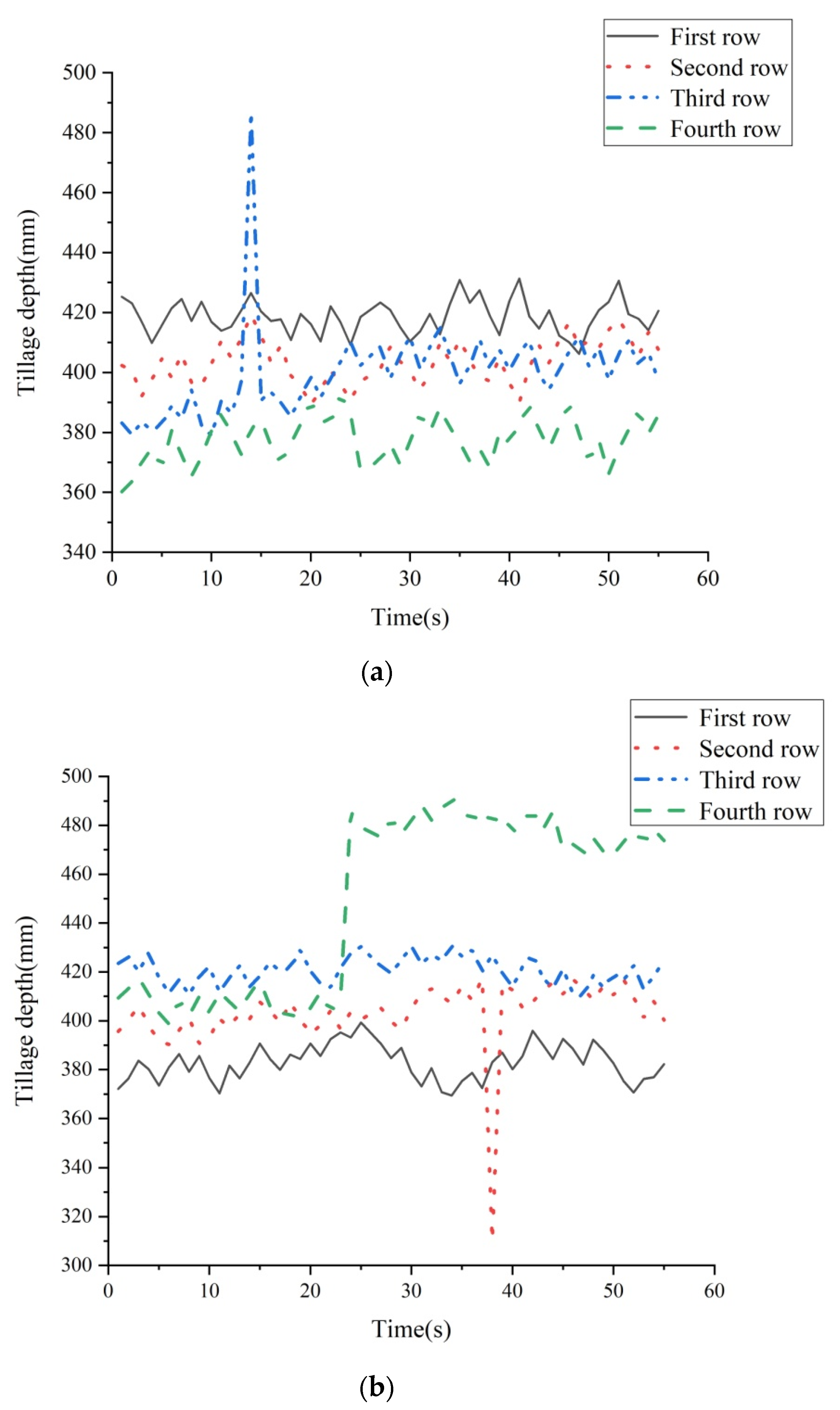
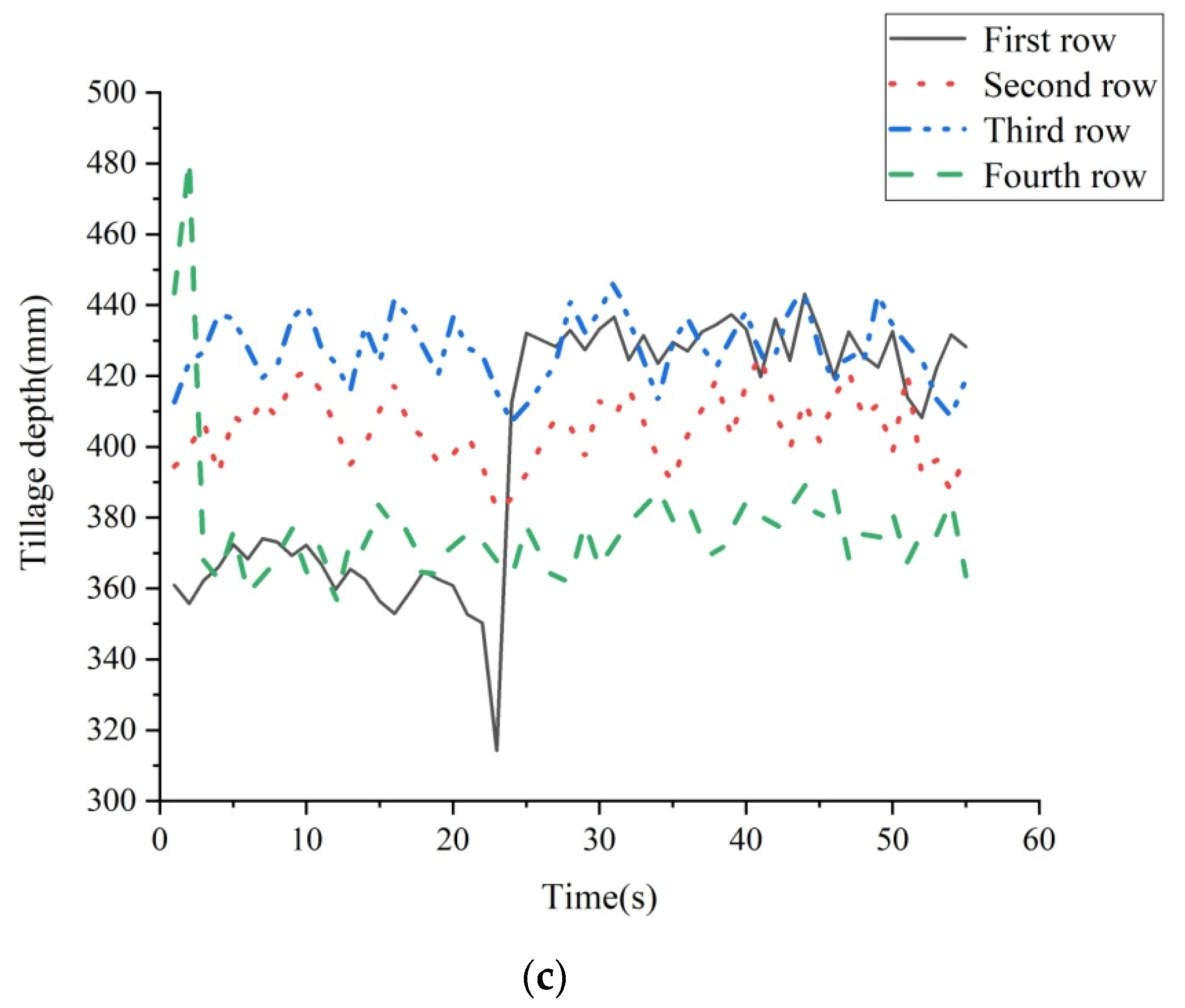
It was proven in Section 3.1 that the method of obtaining the tillage depth by ultrasonic sensors was reliable. The subsoiler with subsoiling assemblies advanced for 55 s under the operation of the monitoring and control system at the forward speeds of 3 km/h, 4 km/h, and 5 km/h, respectively. The tillage depth was recorded on the storage in the cycle of 1 s. Therefore, a total of 660 values of tillage depth detected by four ultrasonic sensors were recorded on the storage. Figure 7 shows changes of the tillage depth of each row at the forward speeds of 3 km/h, 4 km/h, and 5 km/h, with the x-axis representing the forward time of the subsoiler and the y-axis representing the tillage depth, which indicated that the surface of the experiment field had relative height differences along the transverse direction and forward direction of the subsoiler. According to the tillage depth obtained by sensors at the starting point of every subsoiling shovel, the difference of tillage depth between two adjacent subsoiling shovels was 10~35 mm. The tillage depth adjusted on the three-point suspension by the driver showed a trend of decrease (Figure 7a), increase (Figure 7c), and increase first and then decrease(Figure 7b) from the first subsoiling shovel to the fourth subsoiling shovel. The maximum differences of tillage depth between any two subsoiling shovels corresponding to the above trends were 65 mm, 82.5 mm, and 51.4 mm, respectively. The first two values were the difference of tillage depth between the first subsoiling shovel and the fourth subsoiling shovel, while the third value was the difference of tillage depth between the first subsoiling shovel and the third subsoiling shovel. Although the tillage depth of each subsoiling shovel obtained was within the set range at that moment, there were great differences of tillage depth between some subsoiling shovels. If all subsoiling shovels were adjusted simultaneously via the three-point suspension, some shovels obtained more undesired tillage depth, which made soil properties of each subsoiled row different and led to lower yields. Mu et al. [50] found that a difference of 15 cm in tillage depth would result in a 6% reduction in wheat yield. Therefore, tillage depth of each subsoiling shovel needs to be measured and adjusted independently to obtain their respective desired values.
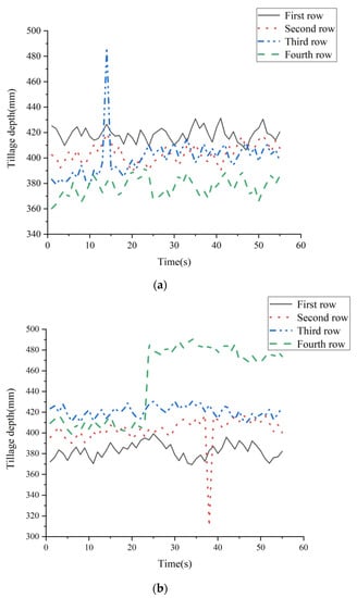
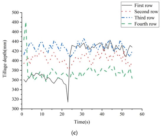
Figure 7.
Results of tillage depth obtained by sensors at forward speeds of (a) 3.0 km/h, (b) 4.0 km/h, and (c) 5.0 km/h.
The surface of the experiment field along the forward direction of the subsoiler was relatively flat, with bumps or depressions in some areas (Figure 7). In the period of tillage depth throughout the set range at the speeds of 3 km/h, 4 km/h, and 5 km/h, the field subsoiled by each subsoiling shovel in 1 s was relatively flat, and the maximum difference of tillage depth between two adjacent areas within a row was about 30 mm. When there was a bump or depression in one section of the row that was subsoiled in 1 s at the three speeds, the difference of tillage depth between two adjacent areas became larger, of which the maximum values belonging to the field with bumps or depressions were all nearly 100 mm. Additionally, these greatly changed tillage depths were less than the minimum set value or greater than the maximum set value. Thanks to the hydraulic cylinder extending or shortening, controlled by the monitoring and control system to lower or lift the subsoiling shovel about 100 mm, the tillage depth was adjusted to be within the set range in time. Thereafter, the tillage depth was almost the value after adjustment with a small change. On the contrary, due to a lack of adjustment, the stability of the tillage depth was poor when there were bumps or depressions on the surface of the subsoiled row, and the desired tillage depth could not be obtained. Celik and Raper [51] stated that soil conditions of adjacent fields could vary greatly even on the same lot. The uneven surface in the field caused different changes in the tillage depths of each row. The subsoiler equipped with the tillage depth monitoring and control system designed in this study was capable of adjusting the undesired tillage depth of each row to be within the set range in a control period at these three forward speeds.
3.3. Transient Response Time
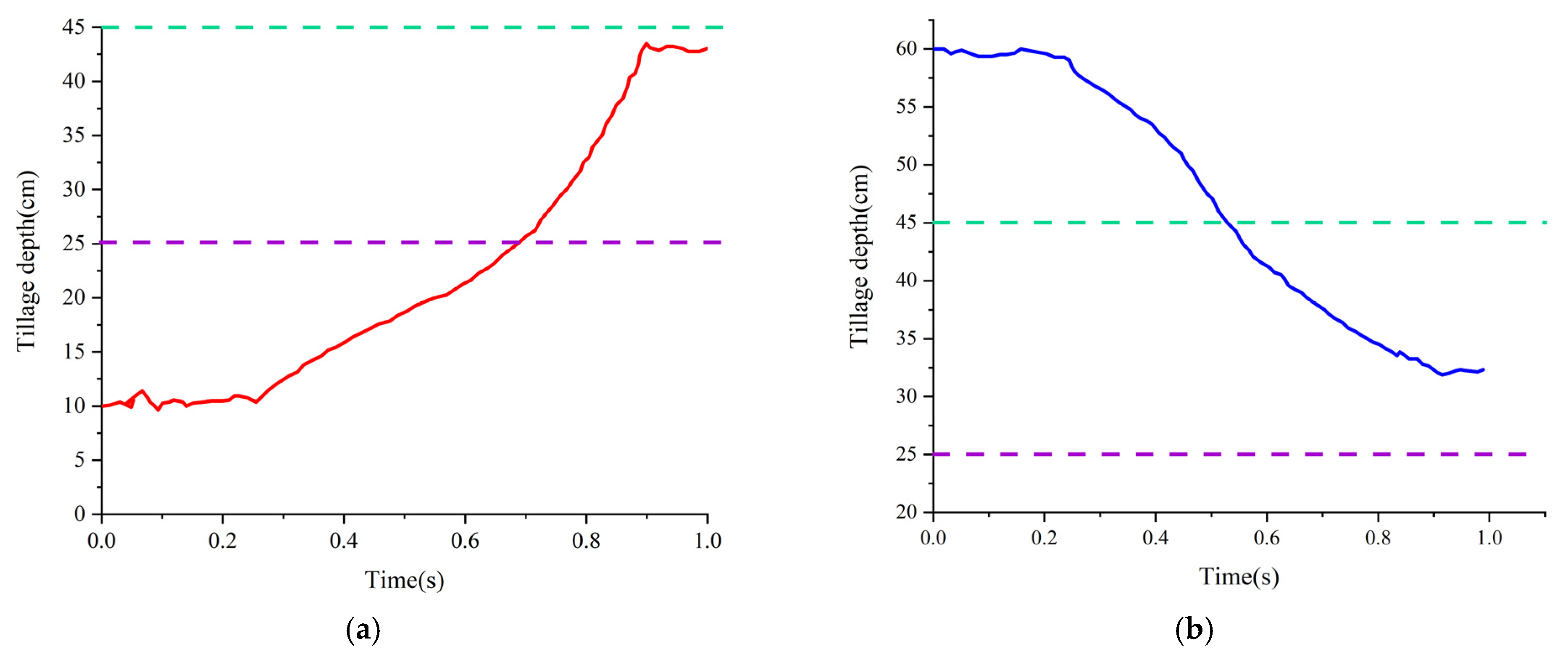
When the tillage depth of the first subsoiling shovel was outside the set range, the tillage depth was changed with time under the monitoring and control function of the system within 1 s, as shown in Figure 8. The red curve represents the change of tillage depth with time when the tillage depth was less than the minimum set value, and the blue curve represents the change of tillage depth with time when the tillage depth was greater than the maximum set value. During the operation, the signal input to the controller from the ultrasonic sensor was analyzed and processed. Then, the controller connected the corresponding value drive circuit of the magnetic exchange valve to make the hydraulic cylinder elongate or shorten. Accordingly, the tillage depth was reduced by lifting the subsoiling shovel or increased by lowering the subsoiling shovel.
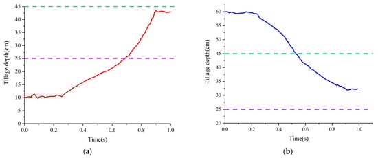
Figure 8.
(a,b) respectively represent changes of tillage depth with time controlled by the system when the tillage depth was less than the minimum set value and more than the maximum set value within 1 s.
As shown in Figure 8, no matter if the tillage depth was less than the minimum set value or greater than the maximum set value, the adjustments of tillage depth almost all started from 0.27 s; this period was the time taken by the monitoring and control system before the hydraulic cylinder began to shorten or elongate. When the tillage depth was 100 mm, the transient response time of the control system was 0.58 s, after which the tillage depth was adjusted to about 425 mm, and almost constant in the remaining 0.15 s. When the tillage depth was 600 mm, the transient response time of the control system was 0.62 s, after which the tillage depth was adjusted to about 325 mm, and almost constant in the remaining 0.11 s. Therefore, the speed of the hydraulic cylinder was 0.54 m/s, and the response time of the hydraulic cylinder was 0.19 s when its adjustment length was 100 mm. Thus, the response time of the control system was 0.46 s. Comparing the obtained results between the tillage depths of 100 mm and of 600 mm, the transient response time of the control system belonging to the former was slightly smaller than that belonging to the latter. This might be because, in this study, the tillage depth was increased via controlling the hydraulic cylinder, shortening to lower the subsoiling shovel. At this time, the drive circuit of the left valve belonging to the magnetic exchange valve was connected, and the hydraulic oil was not impacted, whereas the tillage depth was reduced via controlling the hydraulic cylinder, elongating to lift the subsoiling shovel. At this time, the drive circuit of the right value belonging to the magnetic exchange valve was connected, and the hydraulic oil was impacted. Therefore, the transient response time of the control system was slightly different for the above two tillage depth adjustments. This was similar to the results obtained by Wang [18], that the working-pressure response characteristic of the hydraulic cylinder, which was the excitation source of the vibrating subsoiler, presented different trends with the increase and decrease of pressure. The larger the amplitude of boosting pressure was, the worse the working-pressure response characteristic of the control system was, while the differences of working-pressure response characteristics were small under any amplitude of decreasing pressure. Therefore, the control system developed in this study had good output response characteristics, by which the tillage depth was adjusted to the set range within a control period and remained almost constant, including two tillage depth limits of 100 mm and 600 mm. It was demonstrated that each subsoiling shovel was capable of obtaining the desired tillage depth in every second.
3.4. Advantages of the Control System
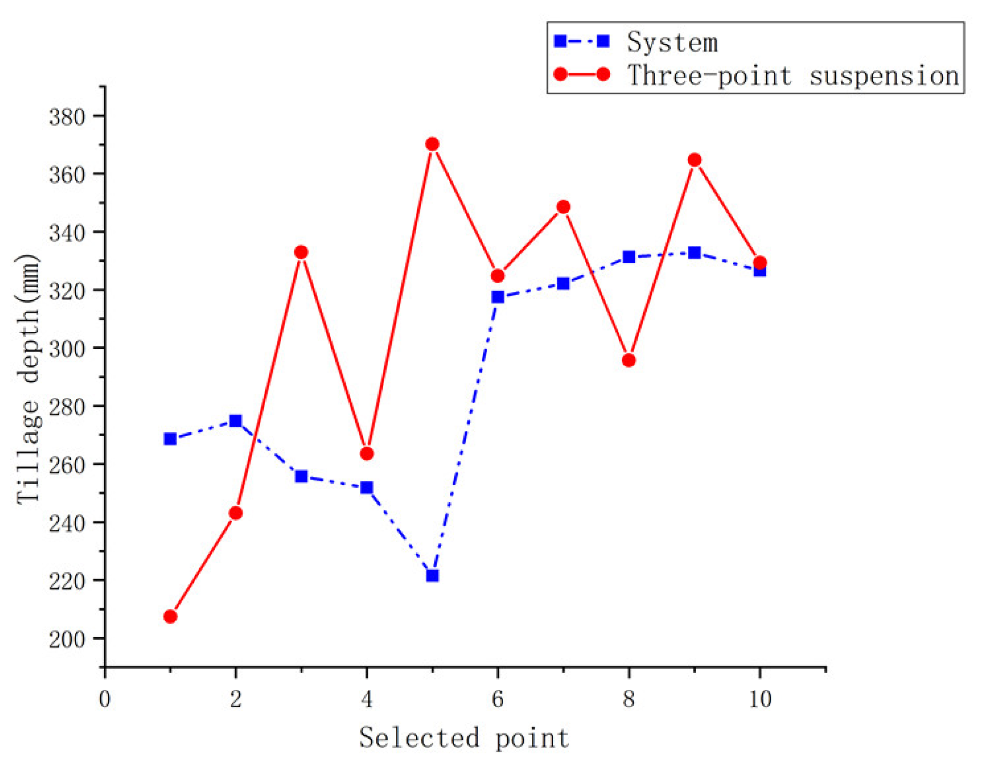
Changes in tillage depth of 10 points respectively selected along the second row of these two operations are shown in Figure 9; the tillage depth represented by the blue dot was obtained under the running state of the monitoring and control system, while the tillage depth represented by the red dot was obtained by only adjusting on the three-point suspension without running system. The mean value and standard deviation of tillage depth at 10 points in blue, respectively, were 290.27 and 38.31, and the mean value and standard deviation of tillage depth at 10 points in red, respectively, were 308.01 and 51.52. It was obvious that the discreteness of the tillage depth data belonging to the latter was greater than that of the former, so the tillage depth data obtained by applying the monitoring and control system developed in this study were more concentrated.
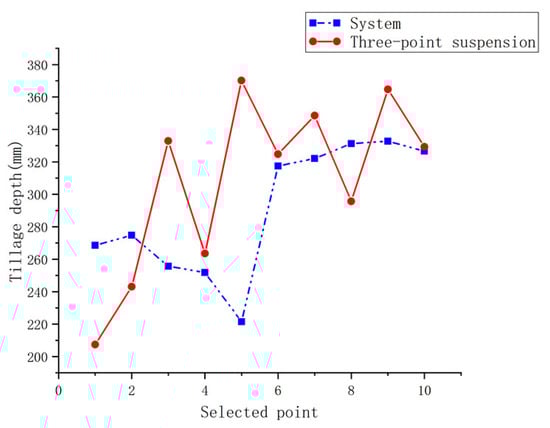
Figure 9.
The tillage depth of the selected 10 points.
As shown in Figure 9, the tillage depth at the fifth measuring point in blue was 221.5 mm, which was less than the minimum set value of tillage depth, while the tillage depth at the sixth measuring point in blue was 317.5 mm, which was within the set range. It indicated that the monitoring and control system was capable of adjusting the tillage depth to the set range in time. The cause of the tillage depth at the fifth measuring point in blue being outside the set range was that this point was within the forward distance obtained by the product of the speed of 5 km/h and the time taken by the system before the hydraulic cylinder began to shorten from 17 s to 18 s. More specifically, the tillage depth was detected and controlled by the system in the period of 1 s; so, when the forward speed was 5 km/h, the advanced distance of the subsoiler was about 1.4 m in 1 s. Thus, the subsoiler was about 23.8 m away from the starting position when it went forward for 17 s and about 25.2 m away from the starting position when it went forward for 18 s. When the fifth measuring point in blue was 24 m away from the starting position, and it was located before the starting adjustment point of tillage depth between 23.8~25.2 m, the tillage depth of this point was outside the set range. For the subsoiling operation only adjusting on the three-point suspension without the running system, the tillage depths at the first and second measuring points in red, respectively, were 207.4 mm and 243.1 mm, which were less than the minimum set value of tillage depth. It illustrated that the tillage depth was not adjusted timely or accurately by this means. In addition, the change of tillage depth among each point was great, indicating that the stability of tillage depth was worse. Moreover, as shown in Figure 10, the partial profiles of tillage furrow selected from each of the 10 points demonstrated that the depth difference of tillage furrow belonging to the unified adjustment of each row was bigger than that belonging to the independent adjustment of a single row. Therefore, it was proven that, compared with adjustment via the three-point suspension, applying the monitoring and control system developed in this study was capable of improving the stability of tillage depth of a single subsoiling shovel and had advantages in enabling each subsoiling shovel to obtain desired tillage depth.
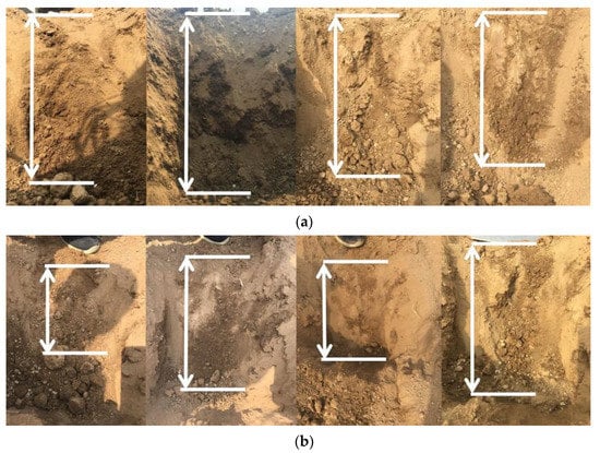
Figure 10.
Partial profiles of tillage furrow selected from each of 10 points. (a,b) respectively belong to an independent adjustment of a single row and unified adjustment of each row.
4. Conclusions
This study developed an electric-hydraulic control system to ensure that each subsoiling shovel was capable of acquiring desired tillage depth in every second. To improving tillage quality, the tillage depth of each row was independently detected by the ultrasonic sensor and adjusted by the hydraulic system. Meanwhile, the detected tillage depth data were displayed via the interactive touch screen and recorded on the storage in a timely manner. Evaluation experiments were conducted in the field. The conclusions were drawn as follows.
- (1)
- Comparing the tillage depth obtained by ultrasonic sensors and measured manually in the field with straw mulching, the errors at the speeds of 3 km/h, 4 km/h, and 5 km/h, respectively, were 8.35%, 8.1%, and 8.38%, which demonstrated that the errors were acceptable and the method of applying ultrasonic sensors to detect the tillage depth was reliable and accurate.
- (2)
- The mean value of the coefficient of the tillage depth stability at the speeds of 3 km/h, 4 km/h, and 5 km/h, respectively, were 97.5%, 97.9%, and 94.9%, which were far better than the standard requirement of a subsoiling machine, and indicated that higher stability of tillage depth was obtained by equipping with the tillage depth monitoring and control system.
- (3)
- The tillage depth monitoring and control system had good output response characteristics. The response time of the control system was 0.46 s. No matter that the tillage depth was less than the minimum set value or greater than the maximum set value, the system was able to accurately detect the change of the tillage depth and timely adjust the tillage depth to the set range within 1 s.
- (4)
- Compared with the unified adjustment of each row via the three-point suspension, applying the system was more advantageous to obtain the desired tillage depth and improve the stability of the tillage depth of each subsoiling shovel. The standard deviations of tillage depth obtained by the independent adjustment of a single row and unified adjustment of each row, respectively, were 38.31 and 51.52.
This study also provided a new detection and control method for improving the stability of tillage depth and obtaining the desired tillage depth of some kinds of tillage machines. Additionally, future comprehensive experiments should be conducted in fields with different soil properties for further clarifying the working performance of the monitoring and control system and improving its applicability in different areas, thus, promoting its application in agricultural production.
Author Contributions
Conceptualization, S.L. and J.H.; methodology, S.L. and J.H.; software, S.L. and C.L.; writing—original draft preparation, S.L.; writing—review and editing, C.L., P.L., H.L. and Z.Z.; funding acquisition, J.H. All authors have read and agreed to the published version of the manuscript.
Funding
This research was funded by the China Agriculture Research System of MOF and MARA (Grant No.CARS-03); Innovative Research Team in University of China (Grant No. IRT13039); Chinese Universities Scientific Fund (Grant No. 2021TC011).
Institutional Review Board Statement
Not applicable.
Informed Consent Statement
Not applicable.
Data Availability Statement
The data presented in this study are available on request from the corresponding author.
Acknowledgments
This research was supported by the 2115 Talent Development Program of China Agricultural University.
Conflicts of Interest
The authors declare no conflict of interest.
References
- Poehlitz, J.; Ruecknagel, J.; Schlueter, S.; Vogel, H.J.; Christen, O. Computed tomography as an extension of classical methods in the analysis of soil compaction, exemplified on samples from two tillage treatments and at two moisture tensions. Geoderma 2019, 346, 52–62. [Google Scholar] [CrossRef]
- Romaneckas, K.; Šarauskis, E.; Avižienytė, D.; Buragienė, S.; Arney, D. The main physical properties of planosol in maize (Zea mays L.) cultivation under different long-term reduced tillage practices in the Baltic region. J. Integr. Agric. 2015, 14, 1309–1320. [Google Scholar] [CrossRef]
- Meharban, S.K.; Rattan, L.; Merrie, A.V. Twenty two years of tillage and mulching impacts on soil physical characteristics and carbon sequestration in Central Ohio. Soil Tillage Res. 2013, 126, 151–158. [Google Scholar] [CrossRef]
- Haytham, M.; Salema, B.; Constantino, V.; Miguel, A.M.; María, G.R.; Silvac, L.L. Short-term effects of four tillage practices on soil physical properties, soil water potential, and maize yield. Geoderma 2015, 237, 60–70. [Google Scholar] [CrossRef] [Green Version]
- Zhang, R.F.; Yang, H.S.; Gao, J.L.; Zhang, Y.Q.; Wang, Z.G.; Fan, X.Y.; Bi, W.B. Effect of subsoiling on root morphological and physiological characteristics of spring maize. Trans. CSAE 2015, 31, 78–84. [Google Scholar] [CrossRef]
- Luo, Z.Z.; Huang, G.B.; Zhang, G.S. Effects of conservation tillage on soil bulk density and water infiltration in dry land of Loess Plateau. Agric. Res. Arid Areas 2005, 23, 7–11. [Google Scholar]
- Somerville, P.D.; May, P.B.; Livesley, S.J. Effects of deep tillage and municipal green waste compost amendments on soil properties and tree growth in compacted urban soils. J. Environ. Manag. 2018, 227, 365–374. [Google Scholar] [CrossRef] [PubMed]
- Hargreaves, P.R.; Baker, K.L.; Graceson, A.; Bonnett, S.; Ball, B.C.; Cloy, J.M. Soil compaction effects on grassland silage yields and soil structure under different levels of compaction over three years. Eur. J. Agron. 2019, 109, 1–9. [Google Scholar] [CrossRef]
- Kristoffersen, A.O.; Riley, H. Effects of soil compaction and moisture regime on the root and shoot growth and phosphorus uptake of barley plants growing on soils with varying phosphorus status. Nutr. Cycl. Agorecosyst. 2005, 72, 135–146. [Google Scholar] [CrossRef]
- Singh, K.; Choudhary, O.P.; Singh, H.P.; Singh, A.; Mishra, S.K. Sub-soiling improves productivity and economic returns of cotton-wheat cropping system. Soil Tillage Res. 2019, 189, 131–139. [Google Scholar] [CrossRef]
- Borek, L. Effect of double subsoiling on physical properties of soil lessives. Acta Sci. Pol. 2016, 15, 21–34. [Google Scholar] [CrossRef]
- Lzumi, Y.; Yoshida, T.; Lijima, M. Effects of subsoiling to the non-tilled field of wheat-soybean rotation on the root system development, water uptake, and yield. Plant Prod. Sci. 2009, 12, 327–335. [Google Scholar] [CrossRef] [Green Version]
- Guaman, V.; Bath, B.; Hagman, J.; Gunnarsson, A.; Persson, P. Short time effects of biological and inter-row subsoiling on yield of potatoes grown on a loamy sand, and on soil penetration resistance, root growth and nitrogen uptake. Eur. J. Agron. 2016, 80, 55–65. [Google Scholar] [CrossRef]
- He, J.; Li, H.W.; Chen, H.T.; Lu, C.Y.; Wang, Q.J. Research progress of conservation tillage technology and machine. Trans. Chin. Soc. Agric. Mach. 2018, 49, 1–18. [Google Scholar] [CrossRef]
- Wang, S.B.; Guo, L.L.; Zhou, P.C.; Wang, X.J.; Shen, Y.; Han, H.F.; Ning, T.Y.; Han, K. Effect of subsoiling depth on soil physical properties and summer maize (Zea mays L.) yield. Plant Soil Environ. 2019, 65, 131–137. [Google Scholar] [CrossRef] [Green Version]
- Schneider, F.; Don, A.; Hennings, I.; Schmittmann, O.; Seidel, S.J. The effect of deep tillage on crop yield-What do we really know? Soil Tillage Res. 2017, 174, 193–204. [Google Scholar] [CrossRef]
- Sun, M.; Gao, Z.Q.; Ren, A.X.; Deng, Y.; Zhao, W.F.; Zhao, H.M.; Yang, Z.P.; He, L.H.; Zong, Y.Z. Contribution of Subsoiling in Fallow Period and Nitrogen Fertilizer to the Soil-Water Balance and Grain Yield of Dry-Land Wheat. Int. J. Agric. Biol. 2015, 17, 175–180. [Google Scholar]
- Feng, X.M.; Hao, Y.B.; Latifmanesh, H.; Lal, R.; Cao, T.H.; Guo, J.R.; Deng, A.X.; Song, Z.W.; Zhang, W.J. Effects of subsoiling tillage on soil properties, maize root distribution, and grain yield on mollisols of northeastern China. Soil Tillage Conserv. Manag. 2018, 110, 1607–1615. [Google Scholar] [CrossRef]
- Pereira, D.P.; Fiedler, N.C.; Juliao, S.L. Efficiency of subsoiling depth according to the slope of the land. Cerene 2012, 18, 607–612. [Google Scholar] [CrossRef]
- Wang, Y.X. Research and Experiment on a Tillage Depth Control System for Hydraulically Self-Excited Subsoiler. Ph.D. Thesis, China Agriculture University, Beijing, China, 2019. [Google Scholar]
- Bernsten, R.; Berre, B.; Torp, T.; Aasen, H. Tine forces established by a two-level model and the draught requirement of rigid and flexible tines. Soil Tillage Res. 2006, 90, 230–241. [Google Scholar] [CrossRef]
- Karoonboonyanan, R.; Salokhe, V.M.; Niyamapa, T.; Nakashima, H. Vibration effects on the performance of a single-shank subsoiler. Agric. Eng. Int. CIGR Ejournal 2008, 6, 126–147. [Google Scholar]
- Radite, P.; Hermawan, W.; Rizkianda, A.B.; Crosby, H.B. Experimental investigation on the application of vibration to reduce draft requirement of subsoiler. Int. Agric. Eng. J. 2010, 19, 31–38. [Google Scholar]
- Wang, Y.X.; Osman, A.N.; Zhang, D.X.; Yang, L.; Cui, T.; Zhong, X.J. Optimized design and field experiment of a staggered vibrating subsoiler for conservation tillage. Int. J. Agric. Biol. Eng. 2019, 12, 59–65. [Google Scholar] [CrossRef]
- Eshagh, B.A.; Tabatabaeifar, A.; Keyhain, A.R.; Raoufat, M.H. Development and field evaluation of an oblique blade subsoiler and comparison of performance with a conventional L-shape subsoiler. J. Agric. Sci. 2002, 12, 67–81. [Google Scholar]
- Jafari, R.; Raoufat, M.H.; TavakoliHashjin, T. Soil bin performance of a modified bentleg plow. Trans. ASABE. 2008, 24, 301–307. [Google Scholar]
- Raper, R.L. Force requirements and soil disruption of straight ang bentleg subsoilers for convention tillage system. Appl. Eng. In Agric. 2005, 21, 787–794. [Google Scholar] [CrossRef] [Green Version]
- Raper, R.L. Subsoiler shapes for site-specific tillage. Appl. Eng. Agric. 2005, 21, 25–30. [Google Scholar] [CrossRef]
- Zhao, J.; He, P.X.; Li, Q.D.; Jiang, M.; Kang, J.; Liu, H.B.; Zhu, K.X. Design of depth display system for micro-tiller. J. Agric. Mech. Res. 2016, 10, 83–86. [Google Scholar] [CrossRef]
- Li, Q.L.; Sun, Y.J.; Sun, Y.T.; Shen, J.X.; Chen, G.; Dou, Q.Q. Development of DSP-based joint operations subsoiling machine monitoring system. J. Agric. Mech. Res. 2016, 11, 118–122. [Google Scholar] [CrossRef]
- Xie, B.; Li, H.; Zhu, Z.X.; Mao, E.R. Measuring tillage depth for tractor implement automatic using inclinometer. Trans. CSAE 2013, 39, 15–21. [Google Scholar] [CrossRef]
- Ayiding, K.; Wu, M.T.; He, P.X.; Liu, X.R.; Sun, B. The control system of automatic adjust for plowing depth. J. Agric. Mech. Res. 2013, 3, 160–163. [Google Scholar] [CrossRef]
- Wang, Y.X.; Jing, H.R.; Zhang, D.X.; Cui, T.; Zhong, X.J.; Yang, L. Development and performance evaluation of an electric-hydraulic control system for subsoiler with flexible tines. Comput. Electron. Agric. 2018, 151, 249–257. [Google Scholar] [CrossRef]
- Jia, H.L.; Guo, M.Z.; Yu, H.B.; Li, Y.; Feng, X.Z.; Zhao, J.L.; Qi, J.T. An adaptable tillage depth monitoring system for tillage machine. Biosyst. Eng. 2016, 151, 187–199. [Google Scholar] [CrossRef]
- Mouazen, A.M.; Anthonis, J.; Saeys, W.; Ramon, H. An automatic depth control system for online measurement of spatial variation in soil compaction.1.Sensor design for measurement of frame height variation from soil surface. Biosyst. Eng. 2004, 89, 139–150. [Google Scholar] [CrossRef]
- Adamchuk, V.I.; Hummel, J.W.; Morgan, M.T.; Upadhyaya, S.K. On-the-go soil sensors for precision agriculture. Comput. Electron. Agric. 2004, 44, 71–91. [Google Scholar] [CrossRef] [Green Version]
- Yuan, Y.W.; Fang, X.F.; Yang, B.N.; Liang, X.X.; Dong, X.; Zhou, L.M.; Zhang, J.N. A Suspended Subsoiler and Its Online Detection Device and Method, CHN, CN104977586-A, 14 October 2015. Available online: http://pss-system.cnipa.gov.cn/sipopublicsearch/portal/uiIndex.shtml?params=991CFE73D4DF553253D44E119219BF31366856FF4B15222634FE161157CF765B (accessed on 18 September 2021).
- Li, Z.X. Research and design of operating depth measurement apparatus for farm implement. Trans. Chin. Soc. Agric. Mach. 2000, 31, 8–91. [Google Scholar] [CrossRef]
- Nie, Y.H.; Kang, J.; He, J.H.; He, P.X.; Li, Q.R. Deep tillage automatically adjust the design and test of control system. J. Agric. Mech. Res. 2015, 2, 143–145. [Google Scholar] [CrossRef]
- Suomi, P.; Oksanen, T. Automatic working depth control for seed drill using ISO 11783 remote control messages. Comput. Electron. Agric. 2015, 116, 30–35. [Google Scholar] [CrossRef]
- Topcon Agriculture Releases Tillage Depth Control Powered by Norac. Available online: https://www.topconpositioning.com/insights/topcon-agriculture-releases-tillage-depth-control-powered-norac (accessed on 16 June 2021).
- John Deere 2633VT with TruSet™ Tillage Technology. Available online: https://www.deere.com/en/tillage/truset/ (accessed on 16 June 2021).
- CASE IH Tillage Tools Equipped with Advanced Farming System. Available online: https://www.caseih.com/northamerica/en-us/products/advanced-farming-systems/field-solutions/afs-soil-command (accessed on 18 June 2021).
- Chen, L.Q.; Li, Z.Q.; Yang, J.J.; Song, Y. Lateral Stability Control of Four-Wheel-Drive Electric Vehicle Based on Coordinated Control of Torque Distribution and ESP Differential Braking. Actuators 2021, 10, 135. [Google Scholar] [CrossRef]
- Zhang, Z.; Jia, X.H.; Yang, T.; Gu, Y.L.; Wang, W.W.; Chen, L.Q. Multi-objective optimization of lubricant volume in an ELSD considering thermal effects. Int. J. Thermal Sci. 2021, 164. [Google Scholar] [CrossRef]
- Nielsen, S.K.; Norremark, M.; Green, O. Sensor and control for consistent seed drill coulter depth. Comput. Electron. Agric. 2016, 127, 690–698. [Google Scholar] [CrossRef]
- Nielsen, S.K.; Munkholm, L.J.; Lamande, M.; Norremark, M.; Skou-Nielsen, N.; Edwards, G.T.C.; Green, O. Seed drill instrumentation for spatial coulter depth measurements. Comput. Electron. Agric. 2017, 141, 207–214. [Google Scholar] [CrossRef]
- China Machinery Industry Standards, 2015. Ministry of Industry and Information Technology of PR China. Specifications for Subsoiling Tillage. NT/T 2845–2015. Available online: https://www.docin.com/p-1652675474.html. (accessed on 10 June 2016).
- Yang, S.M.; Yang, Q.; Yang, Y.H.; Yang, S.C. An ultrasonic-based header height control system of the combine harvester. J. Agric. Mech. Res. 2008, 10, 134–137. [Google Scholar] [CrossRef]
- Mu, X.Y.; Zhao, Y.L.; Liu, K.; Ji, B.Y.; Guo, H.B.; Xue, Z.W.; Li, C.H. Responses of soil properties, root growth and crop yield to tillage and crop residue management in a wheat–maize cropping system on the North China Plain. Eur. J. Agron. 2016, 78, 32–43. [Google Scholar] [CrossRef]
- Celik, A.; Raper, R.L. Design and evaluation of ground-driven rotary subsoilers. Soil Tillage Res. 2012, 124, 203–210. [Google Scholar] [CrossRef]


Publisher’s Note: MDPI stays neutral with regard to jurisdictional claims in published maps and institutional affiliations. |
© 2021 by the authors. Licensee MDPI, Basel, Switzerland. This article is an open access article distributed under the terms and conditions of the Creative Commons Attribution (CC BY) license (https://creativecommons.org/licenses/by/4.0/).