Article

Microstructure Characterization and Mechanical Property of Mg/Al Laminated Composite Prepared by the Novel Approach: Corrugated + Flat Rolling (CFR)

College of Mechanical and Vehicle Engineering, Taiyuan University of Technology, Taiyuan 030024, China
*
Author to whom correspondence should be addressed.
Metals 2019, 9(6), 690; https://doi.org/10.3390/met9060690
Submission received: 28 May 2019 / Revised: 9 June 2019 / Accepted: 13 June 2019 / Published: 17 June 2019

Abstract

:
In this paper, Mg/Al laminated composites were successfully prepared at 400 °C by corrugated + flat rolling (CFR) with reduction ratios of 35% and 25% and subsequent annealing treatments were conducted at 200–350 °C for 30 min. A two-dimensional model was established to analyze the strain distribution during the first corrugated rolling process. Simulation results indicated that severe plastic deformation was formed at trough positions, which included more numerous refined grains than in the peak positions. The interfacial microstructure and mechanical property of the flattened composites along the rolling direction (RD) and the transverse direction (TD) were investigated. The results revealed that longitudinal discontinuous and transverse continuous interfacial intermetallic compounds (IMCs) were observed of the flattened as-rolled sample. Spatial distribution was provided for the grain microstructure along the thickness and rolling direction for AZ31B magnesium alloys of the CFR as-rolled composite. Mechanical property results showed that the longitudinal ultimate tensile strength (UTS) and elongation (EL) of the as-rolled sample reached 255 MPa and 4.14%, respectively. The as-rolled UTS along TD reached 325 MPa, about 30% higher than that along the RD. After heat treatment, the anisotropy of mechanical properties remained. The microstructure evolution and mechanical properties were discussed in detail.

1. Introduction

Bimetallic laminated composites have attracted much attention because of their excellent properties [1,2,3,4,5,6]. Magnesium alloys with low density, light weight, and high specific strength and stiffness are widely used in aerospace, automotive, and electronic industries [7,8,9,10,11]. However, the applications of magnesium alloys are greatly restricted due to their poor corrosion resistance [12,13]. In contrast, aluminum alloys are widely used in mechanical and aerospace fields due to their excellent properties, including light weight, high corrosion resistance, low cost, and good plastic formability [14,15,16]. Therefore, the Mg/Al laminated composites which combine the advantages of substrates and achieve appropriate coordination have attracted worldwide attention [7,17,18,19,20].
At present, various techniques have been applied to fabricate Mg/Al laminated composites, such as explosive welding, diffusion bonding, porthole die co-extrusion + hot rolling, and hot-roll bonding. For instance, Chen [20] prepared a Mg/Al laminated composite by explosive welding + five-pass hot rolling. The mechanical properties of the composite increase first and then decrease with the increase of the annealing temperature and holding time. Considering safety and environmental pollution, this method appears to be unsuitable for wide application. Liu [21] obtained Mg/Al composites via vacuum diffusion bonding, and the growth kinetic equations and different diffusion coefficients were calculated. Due to the low efficiency and long period of the experiment, it is difficult to realize continuous production. Tang [22] studied Al/Mg/Al sheets manufactured by porthole die co-extruding and subsequent hot rolling, showing a tensile strength of 149 MPa and an elongation of 13% of the Al/Mg/Al sheet rolled at 300 °C with a 65% reduction ratio. Among these methods, hot rolling is considered to be the most popular method for preparing Mg/Al laminated composites. However, problems, such as poor plate warpage and low bonding strength, still exist in the Mg/Al laminated composites. Al/Mg/Al laminated composites are prepared by hot rolling at 400 °C and annealed for 1–4 h in the temperature range of 200–400 °C, as reported by Nie [17]. Their results show that the thicker intermetallic compounds (IMCs) greatly deteriorate the bonding strength and plasticity due to the nucleation and quick propagation of cracks along Mg/Al interface after annealing at 400 °C. Abbasi [23] produced a Mg/Al composite by accumulative roll bonding (ARB) at different rolling temperatures. Results reveal that the UTS of the composite is below 150 MPa with a rolling temperature of 400 °C. Furthermore, previous studies [17,21,22,24] mainly focus on the longitudinal tensile properties of Mg/Al laminated composite, and a few experiments have examined the transverse tensile properties. Shimoyama [25] analyzed the longitudinal and transverse tensile properties of AZ31 sheets prepared by periodical straining rolling. Results showed that the transverse tensile test piece exhibited larger elongation than the longitudinal samples. Luo [26] studied the longitudinal and transverse interfacial microstructure of Al/Mg/Al laminated composites after two-pass hot rolling. Their results indicated that the morphology of longitudinal and transverse interfacial microstructure is significantly different, while the specific reasons for this difference were not given in the study.
Based on the corrugated roll, the corrugated + flat rolling (CFR) process is proposed to prepare bimetal laminated composites. In the previous research [27], Cu/Al laminated composites with outstanding mechanical property have been prepared by the CFR process with a low reduction ratio of 20% per pass at room temperature. In the present study, Mg/Al laminated composites are manufactured by this novel rolling approach at 400 °C followed by subsequent annealing treatment at 200–350 °C and the microstructure and mechanical properties are investigated systematically. Furthermore, a 2D model is established to analyze the strain distribution during the first corrugated rolling pass.

2. Experimental Research and Numerical Simulation Analysis

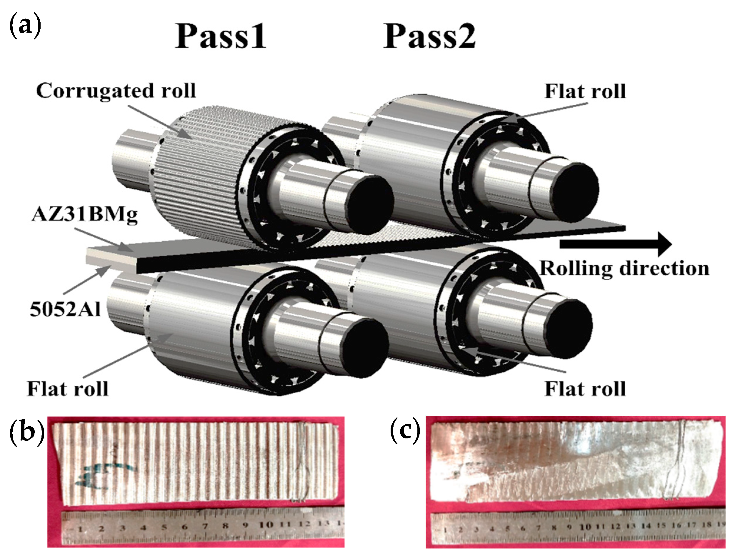
2.1. Experimental Research

Commercial AZ31B magnesium alloy and 5052 aluminum alloy with the specification given in Table 1 were adopted as raw materials in this experiment. The dimensions of the substrate plates were 100 mm × 60 mm × 2 mm. Before rolling, the surface of the substrate plates were ground and cleaned with acetone and alcohol to remove the adhered contamination before stacking. Finally, the two substrates were riveted with aluminum rivets and iron wires.
Mg/Al laminated composites were produced using a two-high laboratory mill with 150 mm diameter without lubrication. One-pass rolling was used for the corrugated rolling process and a one-pass flattening rolling process was applied in this experiment. Rolling speed was maintained at 0.06 m/s and the reduction ratio was 35% for the first CFR pass process and 25% for the second flattening pass. AZ31B contacted with the upper corrugated roll and 5052 corresponded to the lower flat roll during the first corrugated rolling process. The Mg/Al blank was heated at 400 °C for 15 min in a vacuum heating furnace before the first pass. Before the second process, the corrugated composite was heated at 400 °C for 5 min. Finally, the flattened Mg/Al laminated composite with the final thickness of 1.95 mm was acquired. The schematic diagram of the CFR method is shown in Figure 1a. The surface curve of the upper corrugated roll is designed as a sine curve (the amplitude is 0.5 mm and the period is 0.0628 rad) in the first pass. The actual rolled Mg/Al samples by the CFR method can be seen in Figure 1b,c without warping. Subsequent annealing treatment was conducted at 200–350 °C for 30 min with argon protection. Figure 2 shows the metallographic microstructure of the AZ31B plate after heat treatment at 400 °C for 15 min. As can be seen, AZ31B contains polygonal grains with twin structures, and the average grain size is approximately 14 μm.
In this research, the metallographic specimens were cut from the middle of the composite and the surface was ground and polished to reach a mirror finish using alumina polishing fluid. The microstructure of the Mg/Al laminated composite was observed by optical microscope (OM) and scanning electron microscope (SEM, JOE IT500, JEOL Ltd., Tokyo, Japan) equipped with an energy dispersive spectrometer (EDS). Tensile tests were carried out to investigate the longitudinal and transverse mechanical properties of the flattened composites. The tensile tests were conducted according to the standards of GB/T 228.1-2010, and three samples for each test were prepared to obtain the average value. The tensile property was measured using an Instron Series 5969 test machine (Instron Ltd., Norwood, MA, USA) at room temperature with a tensile rate of 0.5 mm/min. The fracture surface was observed to understand the fracture mechanisms.

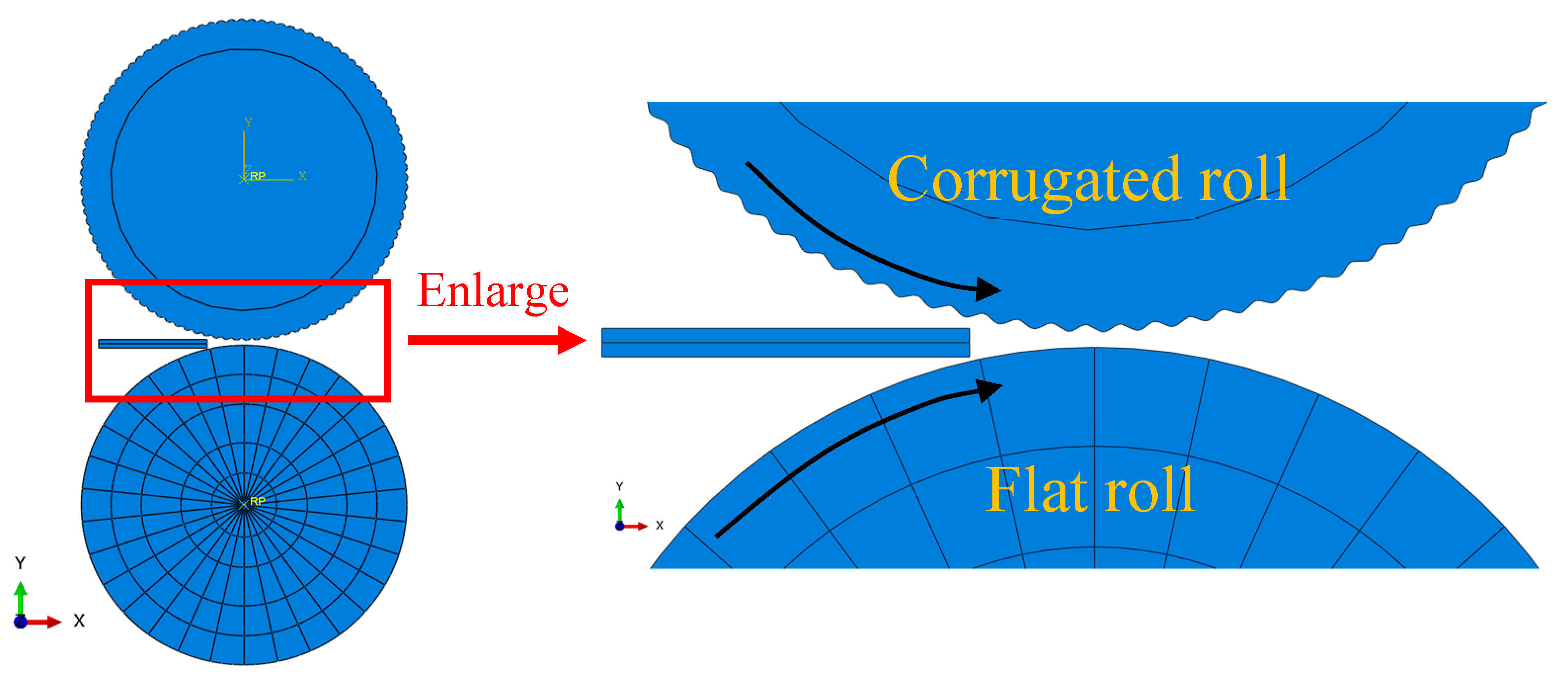
2.2. Numerical Simulation Analysis

In this numerical simulation process, temperature-coupled dynamic explicit analysis is used to realize the elastic-plastic solution of rolling process by using the commercial finite element software ABAQUS 6.14 (Dassault, Vélizy-Villacoublay, France). A 2-D model, including the corrugated roll, conventional flat roll, and substrates, were established in this model. The corrugated rolling simulation process is shown in Figure 3. In the simulation, the thickness of the sheets coincided with the actual rolling experiment while the length of the simulated substrates was half of the actual condition. An adaptive mesh was applied in the magnesium and aluminum sheets, which were each meshed with 10,000 elements after mesh checking to prevent serious element distortion. Taking into account the effect of the rolling temperature, plane strain four-node elements with one integration point (element id: CPE4RT), which can provide an efficient and fast numerical formulation, were used [28]. Rolls were considered as analytical rigid bodies without plastic deformation during the simulation process. The constitutive equation of AZ31B magnesium alloys was obtained by thermal compression tests of cylindrical specimens (Φ 10 × 15 mm) using Gleeble-3800 (Dynamic Systems Inc., El Segundo, CA, USA), and then the obtained stress-strain curve was transformed into the true stress-strain curve which was input into the parameters of the ABAQUS material after discretization. The contact conditions between the rolls and workpiece are calculated by normal hard contact and tangential penalty contact methods. The tangential friction coefficient is set as 0.3. The rolling speed was set as 0.11925 m/s, and the temperature of the substrate sheets was 400 °C. The analysis step is set to an automatic incremental step. In order to simplify the simulation of the rolling process, surface-surface contact between magnesium and aluminum layers was assumed. Therefore, there was no relative movement between the two substrates [29].

3. Results and Discussion

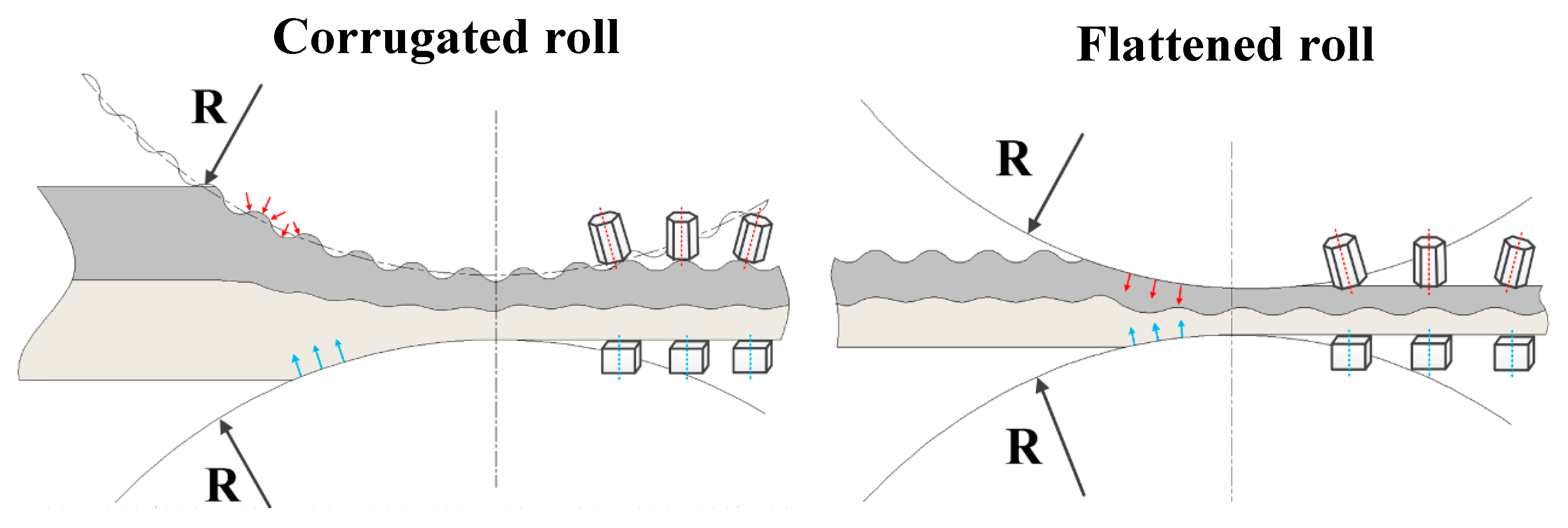
3.1. Interfacial Microstructure and Rolling Simulation of the Corrugated Mg/Al Laminated Composite

Figure 4 shows the SEM images of the interfacial microstructure and OM images of the AZ31B near the upper corrugated roll for corrugated samples prepared by the first CFR pass at typical positions. As can be seen in Figure 4a–b, the interfaces of both peak and trough positions are tightly bonded without cracks and other defects, indicating the better combination at the corrugated Mg/Al interface. As can be seen from Figure 4c, there exist many twin structures with the average grain size of 11.6 μm (Figure 4e) of the magnesium alloy near the top corrugated roll at the peak position, while the grains with the average grain size of 3.01 μm (Figure 4f) at the trough position are significantly refined.
Figure 5 shows the numerical simulation results during the first CFR pass. In the initial stage of rolling (Figure 5a), the equivalent plastic strain (represented in PEEQ) of magnesium and aluminum is zero, and the composite has not yet undergone plastic deformation. During the corrugated roll process (Figure 5b), it can be clearly seen that the PEEQ between the peak position and trough position differs greatly and the strain (Figure 5c) at the trough (2.606) is much larger than that at the peak (0.298) of the contact zone between the magnesium sheet and upper corrugated roll. There exists a stress peak when the true strain reaches 0.1 in the curve in Figure 5d, indicating that the AZ31B deformation curve belongs to a typical dynamic recrystallization type [30].
During the first rolling process, plastic deformation of corrugated Mg/Al composite occurs due to the effect of the rolling force, but the degree of plastic deformation at the peak and trough is remarkably different. A periodic load is applied to the Mg/Al sample by the upper corrugated roll, resulting in the greater rolling force at the trough than that at the peak. According to film theory [31,32,33], brittle layers of the surfaces to be bonded may be broken up under rolling pressure during deformation, and fresh metals appear to be extruded and exposed through widening cracks, forming tight bonding. The bonding quality of composites largely depends on the number of cracks and virgin metals exposed. Due to the corrugated roll in the first CFR pass, notable rolling force is first formed at the trough position, which may cause numerous cracks and fresh metals on the surface to be bonded. During the rolling process, the difference of flow velocity of AZ31B and 5052 results in the occurrence of a cross-shear zone at the Mg/Al interface. The corrugated roll exacerbates the frictional shear deformation at the bonding interface [27]. This can accelerate the breakage of hard and brittle surface and oxide films, promoting fresh metals to flow out and combine in a large area. Furthermore, local strong stress not only promotes the rolling combination of two substrates, but also enhances the ability of interfacial metals to rupture and embed. Thus, the first CFR pass process may increase the contact area between the upper roll and Mg alloy, which not only increases the longitudinal elongation, but also reserves the bending for the extension of magnesium during the second flattening pass.
At the same time, periodic strain is formed due to the special periodic change of corrugated roll. The strain at peak is much lower than that at trough where the metal bears heavy plastic deformation. Severe plastic deformation at the interface provides a large driving force for grain breaking and recrystallization [17]. With the further increase of the plastic strain at the trough position, dislocation accumulation can promote the occurrence of grain boundary-induced recrystallization, and the accumulated dislocation on the sub-grain boundaries can be gradually absorbed by grain boundary diffusion, etc. [34]. Furthermore, the local stress distribution on the corrugated surface of the AZ31B sheet is inhomogeneous, thus, the grains of the AZ31B sheet are not uniform along RD [35].

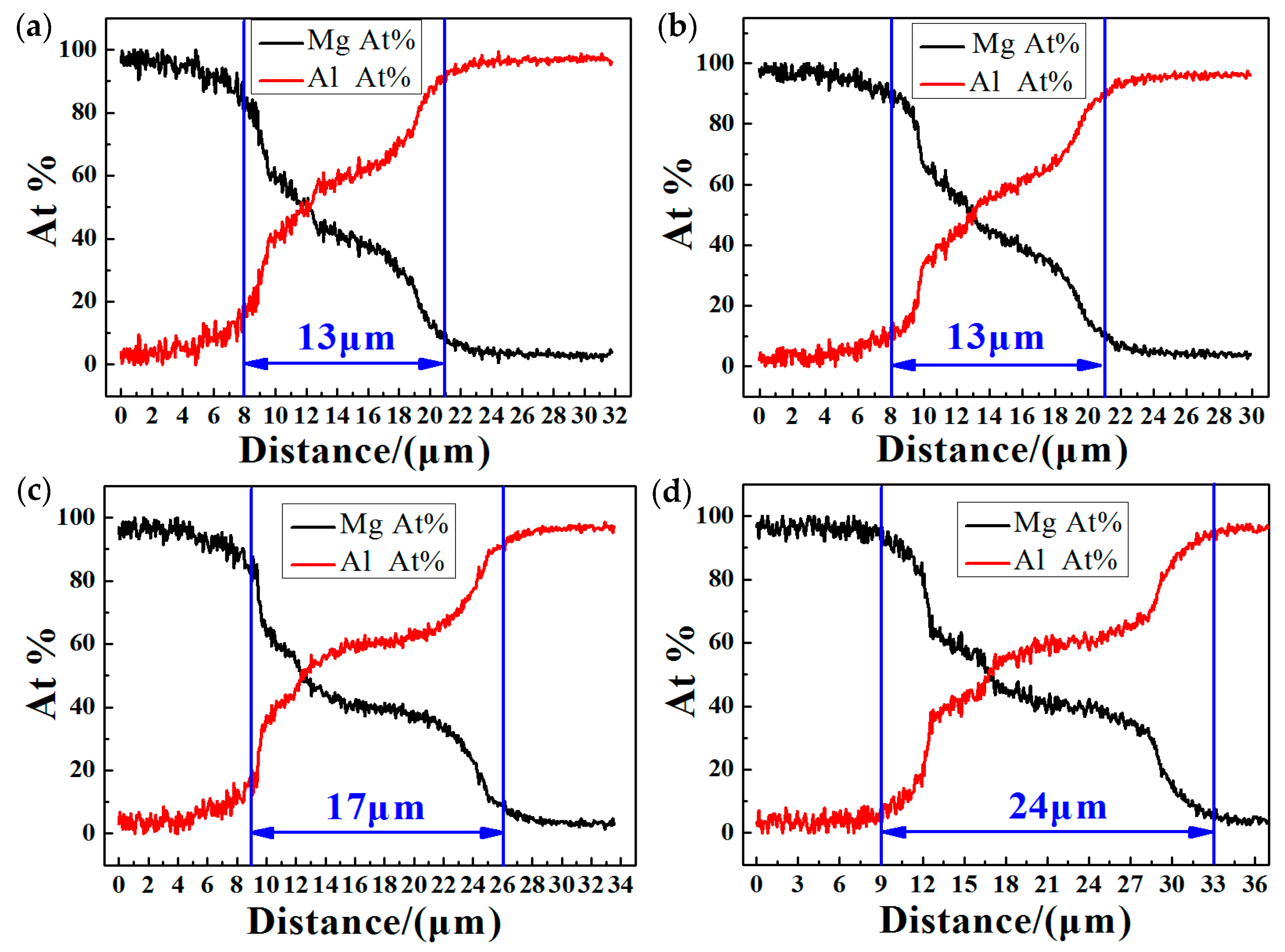
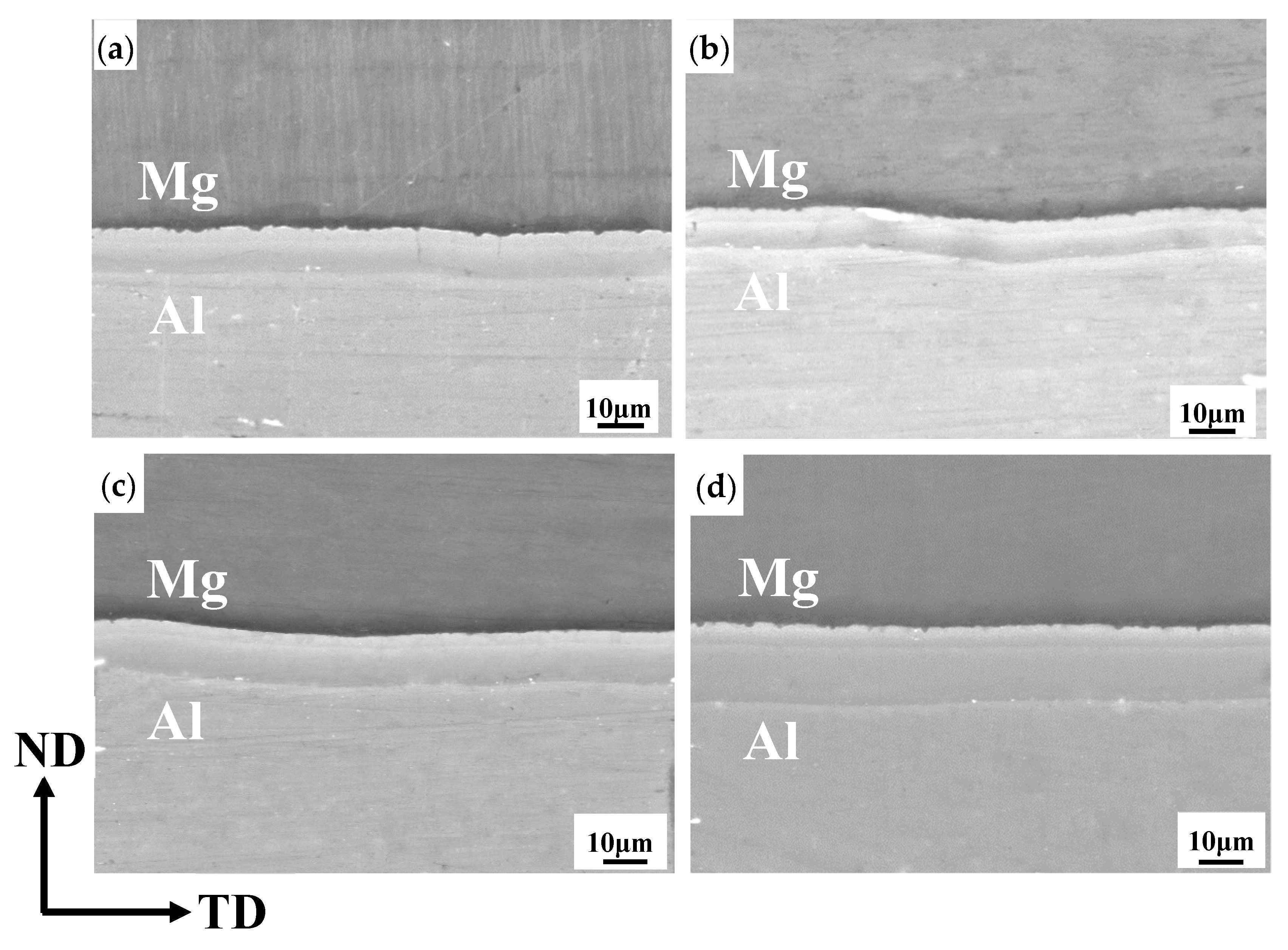
3.2. Interfacial Microstructure after Intermediate Annealing

Figure 6 exhibits the longitudinal (Figure 6a) and transverse (Figure 6b) interfacial SEM micrographs and element line scanning at the trough region after the intermediate annealing at 400 °C for 5 min. Two typical intermetallic layers without fracture are obvious at the interface both along RD and TD. As can be seen from Figure 6c,d, the concentration of Mg elements decreases from the AZ31B to 5052 while the concentration distribution of the Al element is on the contrary. The thickness of the total interface layer in both directions is equal (13 μm) (Figure 6c,d).
To identify the intermetallic layers, EDS quantitative analysis is performed and the results are presented in Table 2. The atomic percentages of Mg and Al are 59.9% and 40.1% at layer A and 38.2% and 61.8% at layer B (Table 2), respectively. According to the Mg-Al binary phase graph [36], it can be indicated that the IMCs of layer A and B are Mg17Al12 and Mg2Al3 phase, respectively. The Mg17Al12 phase is adjacent to the AZ31B plate and the Mg2Al3 phase is close to the 5052 plate. Lee [37] has reported a similar phenomenon in their research. The intermetallic compound phases generate at the interface between Mg and Al of a roll-bonded STS–Al–Mg three-ply clad sheet after heat treatment. Severe plastic deformation (SPD) can lead to the formation of phases as described by Straumal [38]. In Straumal’s research, severe plastic deformation opens the way to produced materials with very stable phase structure and leads to the strong grain refinement of Fe-C alloys. As shown in Figure 6a,b, the Mg2Al3 layer is always thicker than the Mg17Al12 layer. This can be mainly attributed to the activation energy of the Mg2Al3 phase being lower than that of the Mg17Al12 phase, and the diffusion velocity of Mg atoms into the Al matrix is faster than that of Al atoms into the Mg matrix, resulting in a higher inter-diffusion coefficient of the Mg2Al3 phase than that of the Mg17Al12 phase [39,40]. Furthermore, the similar crystal structure between the 5052 substrate (face-centered cubic, FCC) and the Mg2Al3 phase (FCC) promotes the growth of the Mg2Al3 phase, while the different crystal structure between the AZ31B substrate (hexagonal close-packed, HCP) and the Mg17Al12 phase (body-centered cubic, BCC) inhibits the growth of Mg17Al12 [22]. Therefore, the synergistic effect of the above factor contributes to the thick difference between the Mg17Al12 and Mg2Al3 layers shown in Figure 6.

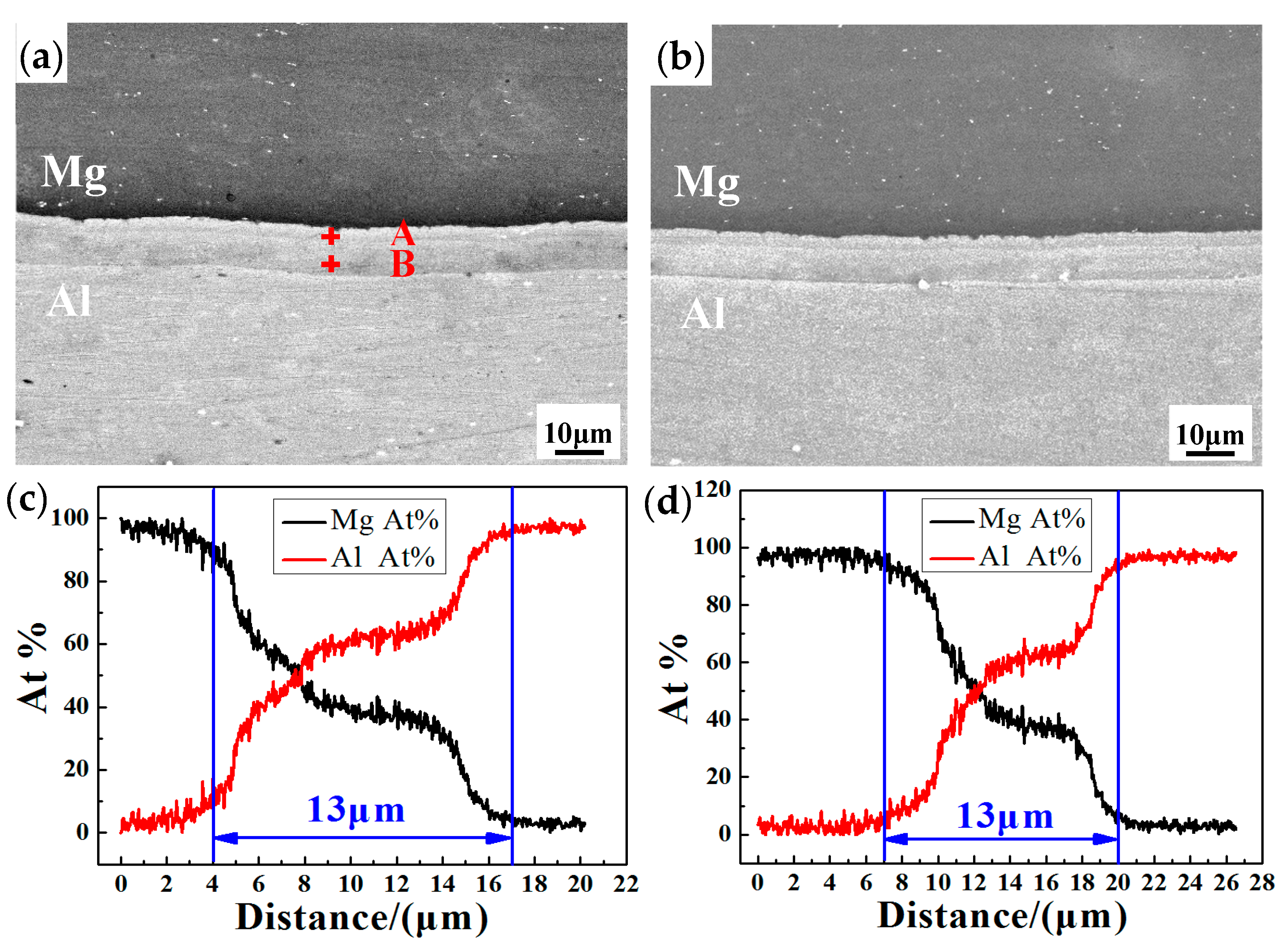
3.3. Interfacial Microstructure of the Flattened Mg/Al Laminated Composite

In the present study, the selected observation area of the Mg/Al interface microstructure is position 1 in Figure 7a. Figure 7b–e shows the longitudinal SEM micrographs and elemental surface scanning distribution, where Mg and Al elements are represented by red and green points. As can be seen, there are IMCs at the interface for the composites with different treatments. Obviously, IMCs are discontinuous for the samples as-rolled and annealed at 200 °C, and a new bonding interface appears marked with red circles (Figure 7b). Considering the continuous IMC layers in Figure 6, the fracture of the IMC layers mainly occur during the second flattening rolling process. Due to the intrinsic brittleness, intermetallic compounds cannot sustain the large plastic deformation along the rolling direction [26]. When annealing at 200 °C, there are no new IMCs at the bonding interface, which is in agreement with the previous study [41] for Mg/Al composites. However, note that composites annealed at 300–350 °C present a continuous lamination interlayer (Figure 7d–e) and the IMCs thickness increases with increasing temperature.
It is known that the diffusion in solid material can be described by Fick’s second law, and the diffusion coefficient becomes higher with the increasing temperature [42]. Two distinct continuous intermetallic phases resulting from the elements’ diffusion can be observed in the samples annealed at 300 °C and 350 °C. The atom movements caused by strong external forces can drive accelerated diffusion in the material [43]. In the early stage of the atomic diffusion process, Mg concentration on the aluminum side and Al concentration on the magnesium side are far below their solubility limit, which provides a driving force for mutual diffusion [22]. Therefore, an Al-based solid solution and a Mg-based solid solution are formed in intermediate transition layer. As the diffusion process proceeds further, the unstable supersaturated solid solution occurs, and the intermetallic phases begin to nucleate. The solubility of magnesium and aluminum exceeds the limit because intermediate diffusion can be enhanced due to the high temperature. Consequently, the continuous IMCs are formed in the samples annealed at 300–350 °C, as shown in Figure 7.
The thickness of IMC layers is calculated according to element line scanning, as shown in Figure 8. The transition layers of the composites annealed at 300–350 °C are thicker than the flattened as-rolled sample and composite annealed at 200 °C (Figure 8). Furthermore, the transition layer thickness of the sample annealed at 350 °C is 24 μm, which is dramatically larger than the 17 μm of the composite annealed at 300 °C. It is noted that the annealing temperature has a remarkable influence on the microstructure in the same holding time.
As shown in Figure 8a,b, comparing with the as-rolled plate, the interfacial diffusion layer of the annealed sample at 200 °C exhibits little change. However, the diffusion layer increases obviously when the annealing temperature exceeds 200 °C. According to the previous literature [41], the growth rate of diffusion layer is related to the diffusion coefficient (K) which can be expressed by the following Arrhenius equation:
K = K 0 exp ( E R T )
where, K 0 , E, and R are the frequency factor (m2/s), activation energy (J/mol) for diffusion, the gas constant (8.314 J/mol K), and T is the absolute temperature in Kelvin (K). It can be seen that the diffusion coefficient increases with the increase of the annealing temperature, which results in the increase of the thickness of the diffusion layer. Of course, the diffusion coefficient (K) of magnesium and aluminum is very low and the final diffusion amount is greatly limited, so the thickness of the diffusion layer is relatively small at the lower annealing temperature (200 °C) [20]. In addition, the diffusion process may also be related to the high strain at different positions during the CFR severe plastic deformation process [44].
Figure 9 exhibits the transverse interfacial microstructure of the flattened composites. The discussed area is position 1 on TD-ND plane in Figure 7a. Transverse interfacial layers of the as-rolled and annealed samples are continuously distributed without fracture, which is obviously different from the longitudinal interlayers (especially the as-rolled and the sample annealed at 200 °C) mentioned in Figure 7. Diffusion layer thickness of as-rolled sample is the same as that annealed at 200 °C, both of which are 13 μm. With the annealing temperature increasing to 300 °C and 350 °C, the interlayer thickness increases to 17 μm and 24 μm, respectively. This is equal to the longitudinal thickness in the same annealing process.
Figure 10 and Figure 11 show the optical microstructure of AZ31B and 5052 of the as-rolled flattened composite, respectively. The microstructure of the peak region consists of fine grains and mechanical twins along ND, as shown in Figure 10a–c. The mean grain size of areas (a), (b), and (c) in position 1 is 3.02 μm, 3.27 μm, and 3.5 μm, respectively, which is smaller than that of areas (d), (e), and (f) in position 2 (3.3 μm, 6.0 μm, and 5.07 μm, respectively) (Figure 10). As can be seen, position 2 (Figure 10d–f) contains a mixture of small recrystallized grains and coarse grains. As for the 5052Al, the grains in position 3 (Figure 11a–c) are obviously elongated, and the average grain size in position 3 (35.2 μm, 33 μm, and 31.6 μm of areas (a), (b), and (c)) is smaller than that in position 4 (40.7 μm, 40.09 μm, and 40.5 μm of areas (d), (e), and (f)). Furthermore, coarse grains are mainly included in position 4.
According to the original microstructure in Figure 2, the remarkable grain refinement can be mainly attributed to the significant effect of severe plastic deformation during the rolling process, corresponding with the research of Shimoyama [25]. Furthermore, note the smaller grain size of position 1 than position 2, and position 3 than position 4, indicating that the metal’s flow lines appear to be affected by the sheet shape. During the flattening process, heavy plastic strain is introduced in position 1 and position 3, so relatively fine recrystallized grains are commonly significant through the thickness direction. Therefore, small recrystallized grains and less coarsened grains can be seen in Figure 10b,c. On the contrary, position 2 mainly consists of numerous coarse grains and small grains in Figure 10e,f, which might be derived from macro shear banding during hot flat rolling [25]. As Haghdadi describes [45], under the external loading, the strain incompatibility develops in the interface of matrixes, and the high density of dislocations provides a strong driving force for grain refinement through severe plastic deformation. This different metal flow pattern may finally lead to the micro-grains’ differential distribution along the thickness direction and longitudinal direction. Additionally, the grain refinement is attributed to the shearing force during severe plastic deformation [45,46].
During the first CFR process, compressive stress of various orientations is formed in the corrugated Mg/Al laminated composite. This means that asymmetric deformation occurs [35], as shown in Figure 12. The upper corrugated roll results in an inhomogeneous local stress distribution at different positions. Thus, the grain structure of AZ31B might be not uniform and microstructure might change with the curve of the corrugated roll. On the contrary, the lower conventional flat roll corresponds to 5052 aluminum and the stress on the aluminum sheet near the flat roll appear to be homogeneous. During the second flattened rolling process, the AZ31B metal at the peak position prepared by the first pass flows downward and sideways, enduring severe plastic deformation under the rolling force. The original coarse grain might be broken and recrystallize during the rolling process and subsequent heat treatment. The Mg/Al laminated composite is elongated and the intrinsically hard and brittle interfacial compounds are broken along the rolling direction [47]. Meanwhile, the transverse extension of composites is often neglected [48]. Considering the matching of surface ripples between the corrugated Mg/Al composite and corrugated roll, the rolling force appears to be uniform along the width direction, which is different from the force along RD. Therefore, for the flattened as-rolled Mg/Al laminated composite, the longitudinal and transverse interfacial microstructures are significantly different. This may lead to the discrepancy of mechanical properties along the rolling direction and transverse direction.

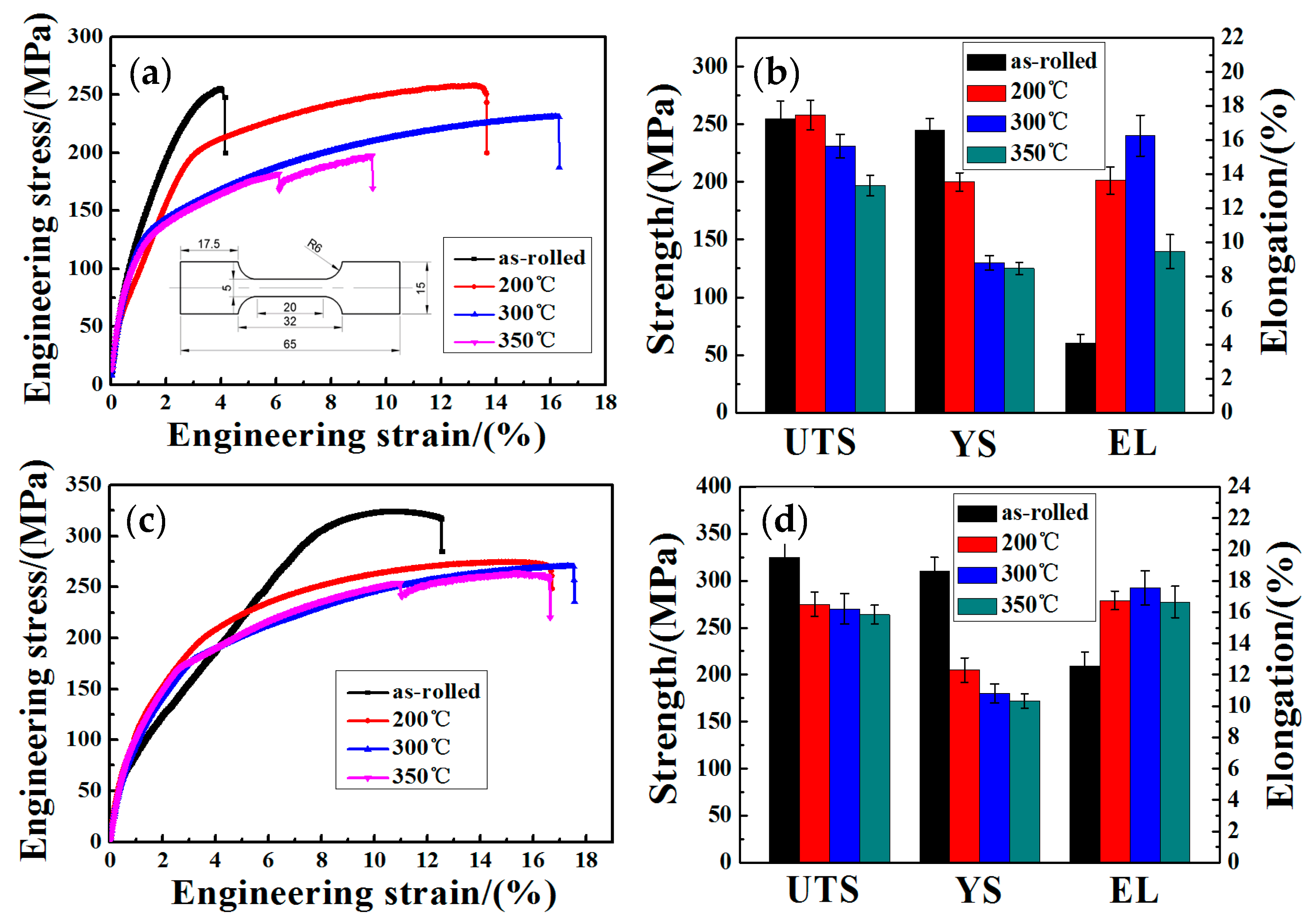
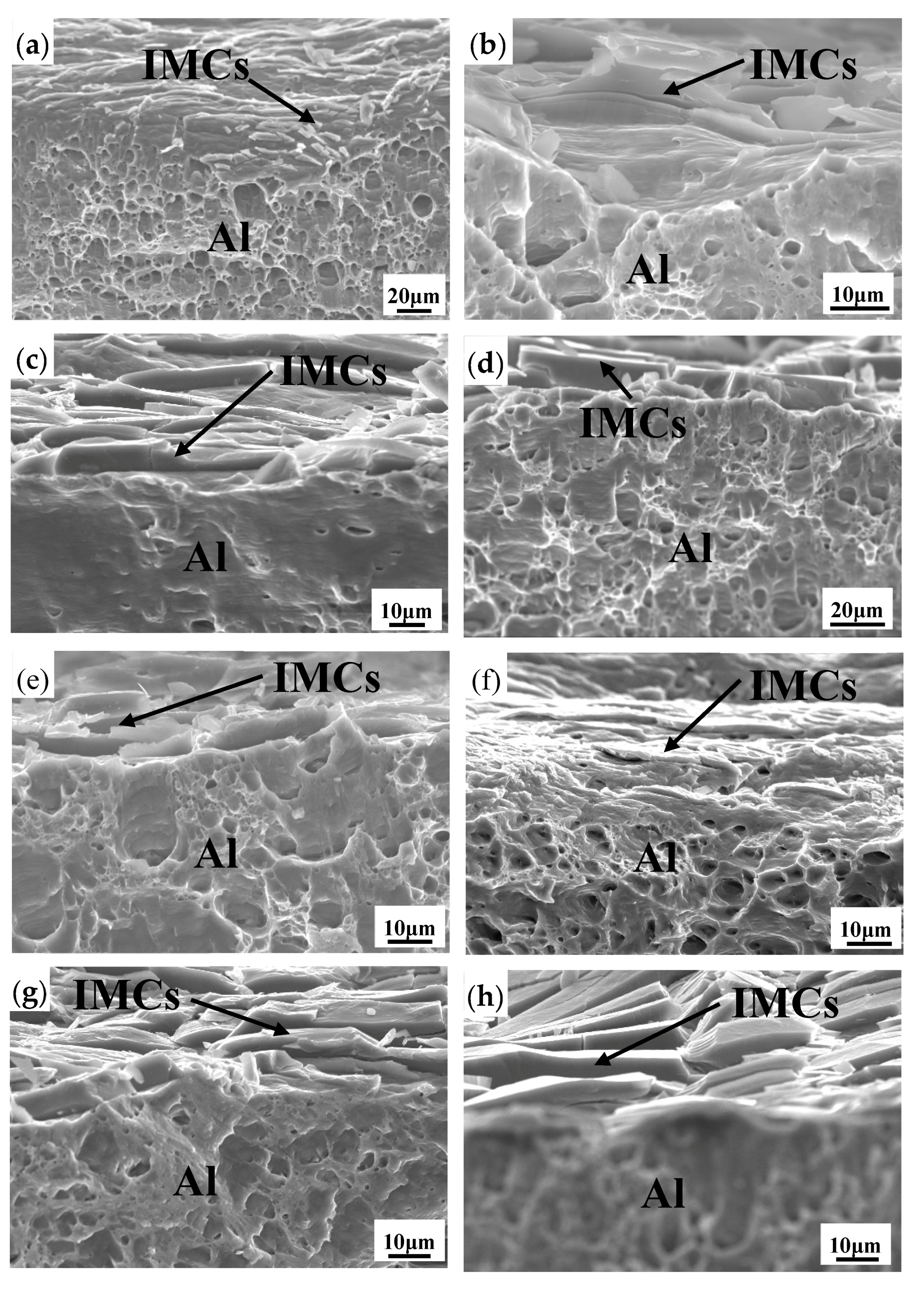
3.4. Mechanical Properties of the Flattened Mg/Al Laminated Composite

Figure 13 shows the tensile properties of flattened samples along longitudinal direction (Figure 13a,b) and transverse direction (Figure 13c,d). The dimension of the tensile specimen can be seen in Figure 13a. According to Figure 13a,b, the as-rolled samples exhibits the typical feature in the processing state with a high ultimate tensile strength (UTS) (255 MPa) and relatively low elongation (4.14%) along RD, which is higher than that obtained by explosive welding and conventional flat rolling (160 MPa and 192 MPa) [19,49]. After heat treatment at 200 °C for 30 min, the UTS maintains the value of as-rolled state, while the elongation reaches 14%, about 250% higher than that of as-rolled composite. This can be mainly attributed to the recovery and stress harmonization during heat treatment. With the increase of the annealing temperature, the UTS decreases gradually, while the elongation reaches the peak value at 300 °C (16.3%) and then declines sharply to 9.5% at 350 °C. The variation of strength mainly results from the elimination of work hardening due to the thermal insulation beyond the recrystallization temperature. For the sample annealed at 350 °C, excepting for the decrease of UTS and EL, a slight decrease of stress can be clearly observed. This can be mainly attributed to the thick IMC layer formed at the interface during heat treatment, as shown in Figure 7 and Figure 9. The difference in UTS between the as-rolled composite and the annealed samples is mainly due to the appearance of intermetallics at the Mg/Al interface. According to the previous research [26], the most primary factors affecting strength and elongation are the thickness and morphology of intermetallic layers caused by reaction diffusion during the fabrication process and subsequent annealing treatment. When the annealing temperature exceeds 300 °C, although recrystallized grains are dominant in the laminate, the brittle nature of the intermetallics decreases the compatible deformation capability, leading to delamination between the matrix layers and interfacial layers. Over-thick IMCs appear to cause interfacial cracks and subsequent crack propagation, resulting in the fracture of the laminated composite. The thickness of IMC layers of the composite annealed at 350 °C reaches 24 μm, which is responsible for the low tensile strength. Although recrystallization occurs during the annealing process at 350 °C, the hard and brittle nature of the IMCs decreases the coordination deformation ability, leading to delamination between the substrates and interface layer [17].
Furthermore, according to Figure 13c,d, the tensile properties of samples along TD exhibit a similar evolution feature compared to the samples along RD, while it is noteworthy that the tensile strength and elongation along TD appear to be higher than that along RD in both as-rolled and heat-treated states. The as-rolled UTS along TD reaches 325 MPa, about 30% higher than that along RD. The heat-treated samples show a similar trend. This indicates that the Mg/Al laminated composite prepared by the CFR process exhibits significant anisotropy of tensile properties, corresponding to the previous studies of a single metal plate. In the research of Shimoyama [25], the transverse tensile test of the 723 K-annealed AZ31B sheet shows larger elongation than longitudinal tensile test and the large planar anisotropy due to the periodical straining process should account for the mechanical anisotropy. Based on the above results, the uniform elongation of as-rolled longitudinal tensile specimens is smaller than that of transverse tensile specimens. This may be attributed to the microstructural differences, such as grain size and a mixture of recrystallized grains and non-recrystallized grains, which come from the hot-deformed microstructure. This spatial distribution of the microstructure might restrict the longitudinal UTS and EL [25]. The reason for the high transverse tensile strength and elongation may result from the grain refinement in a large area along TD. The phenomenon of grain refinement is helpful to improve the mechanical properties of materials [43]. During the first corrugated process, the grains are refined at the trough position, and the severe plastic deformation which causes grain refinement at the interface again occurs in the second pass.
Figure 14 shows the tensile fracture surface on the Al side of the CFR flattened samples along RD (Figure 14a–d) and TD (Figure 14e–h). A large number of dimples can be observed on the surface of the aluminum, indicating the ductile fracture mode [17]. Therefore, it can be deduced that the fracture of flattened composites under different treatment conditions is a ductile fracture, both longitudinal and transverse. Furthermore, massive intermetallic compounds can be clearly seen at the interface. It is noteworthy that numerous lamellar IMCs appear at the tensile interface after treatment at 300 °C and 350 °C, as shown in Figure 14c,d,g,h. Mg alloys have relatively lower plastic deformation capacity than Al alloys, and such mismatch leads to a localized high shear stress along the interface during tensile testing. Intermetallics at the Mg/Al interface and delamination of Mg/Al laminates indicate the crack initiation from the intermetallics leads to a quick propagation along the Mg/Al interface or in the interior of intermetallics before the laminates show strain hardening effect, resulting in the low ultimate tensile stress (UTS) and elongation (EL) for samples annealed at 350 °C. In Lee’s research [50], interface delamination was reported to originate in the Mg2Al3 layer. Macwan [41] pointed out that cracks generally occur at the interface between Mg2Al3 and Fe-containing Mg2Al3 layer close to the Al side in the rolled Al/Mg/Al tri-layer laminated composite, corresponding to the observation in the present research. Thus, it can be seen that the generation, evolution, and growth of the intermetallic compounds at the interface during annealing is a significant factor affecting the mechanical properties of the Mg/Al laminated composites.
Therefore, the brittle IMCs at the Mg/Al interface exhibit a significant effect on the mechanical property of bimetal composites. When interlayers reach a certain thickness, their brittle and hard nature greatly decrease the UTS and EL. Overall, CFR samples annealed at 200 °C and 300 °C for 30 min exhibit better tensile strength and fracture plasticity.

4. Conclusions

In the present work, Mg/Al laminated composites with the final thickness of 1.95 mm were successfully manufactured by the novel corrugated + flat rolling (CFR) method at reduction ratios of 35% and 25%, and subsequent annealing treatments were conducted at 200–350°C for 30 min. The longitudinal and transverse microstructure and mechanical properties of the flattened Mg/Al laminated composites were investigated. The major conclusions can be drawn as follows:
(1)
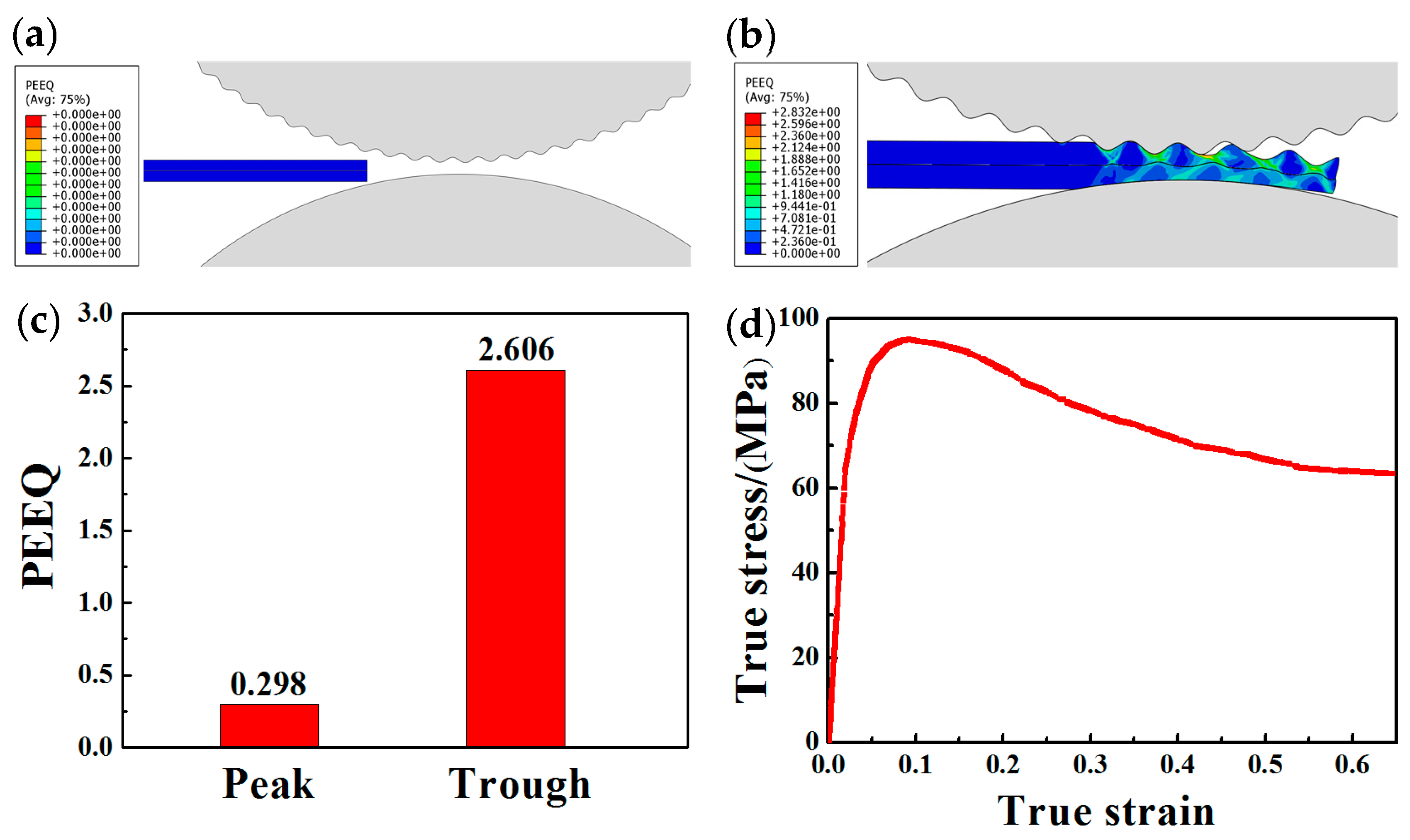
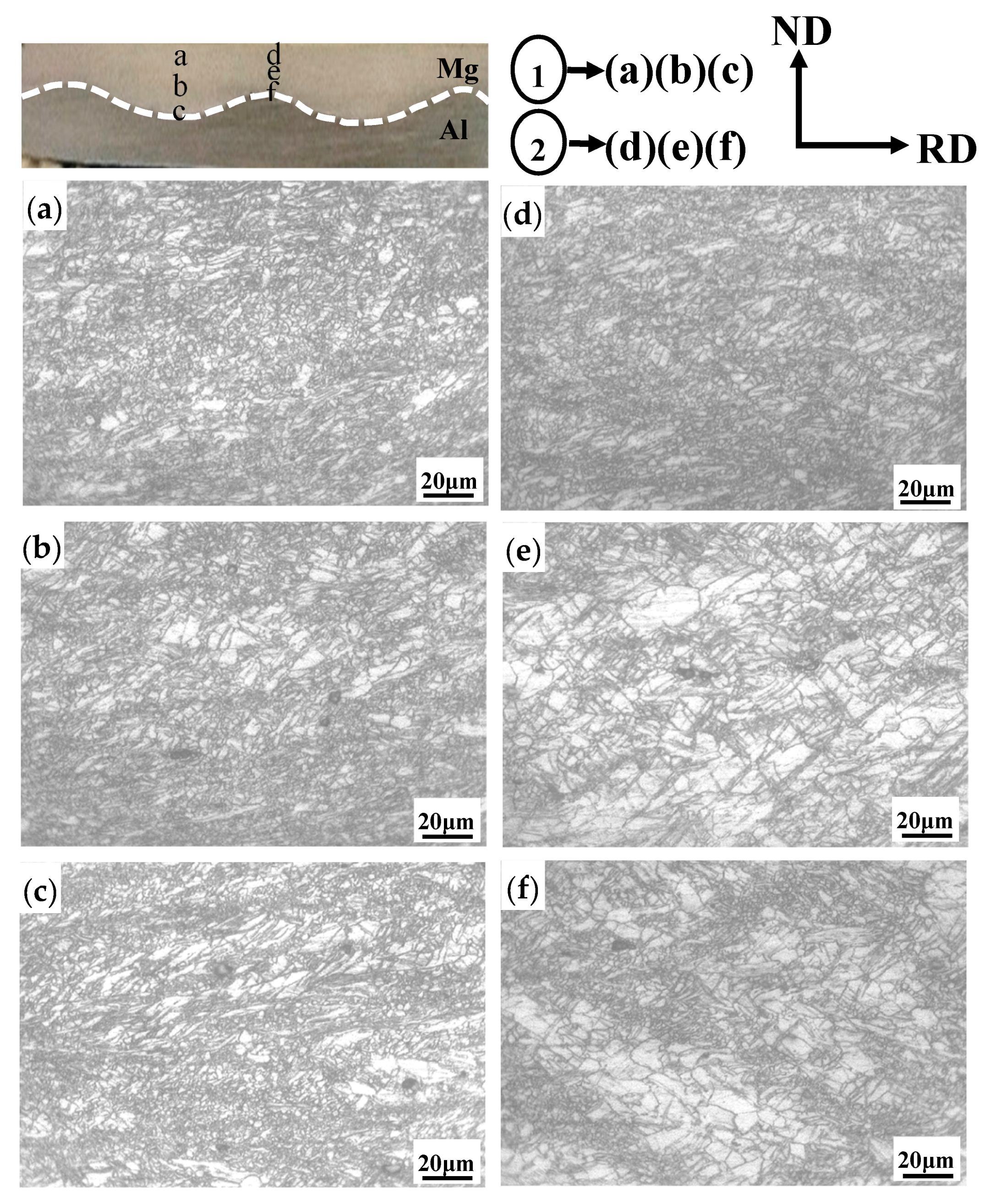
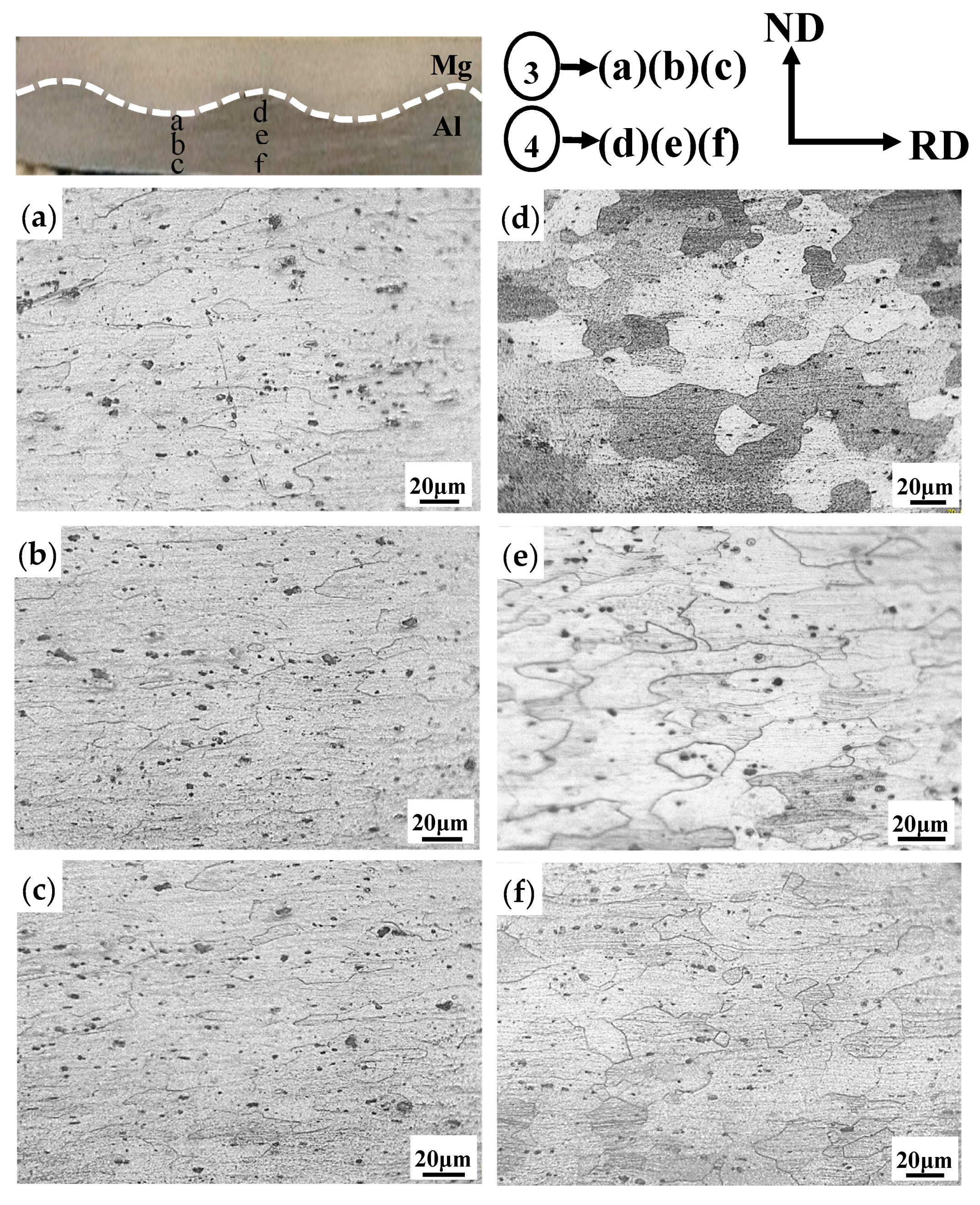
During the first corrugated rolling process, severe plastic deformation occurs at the trough position. This periodic larger strain at the trough position contributes to the tight bonding and grain refinement than that of the peak position.
(2)
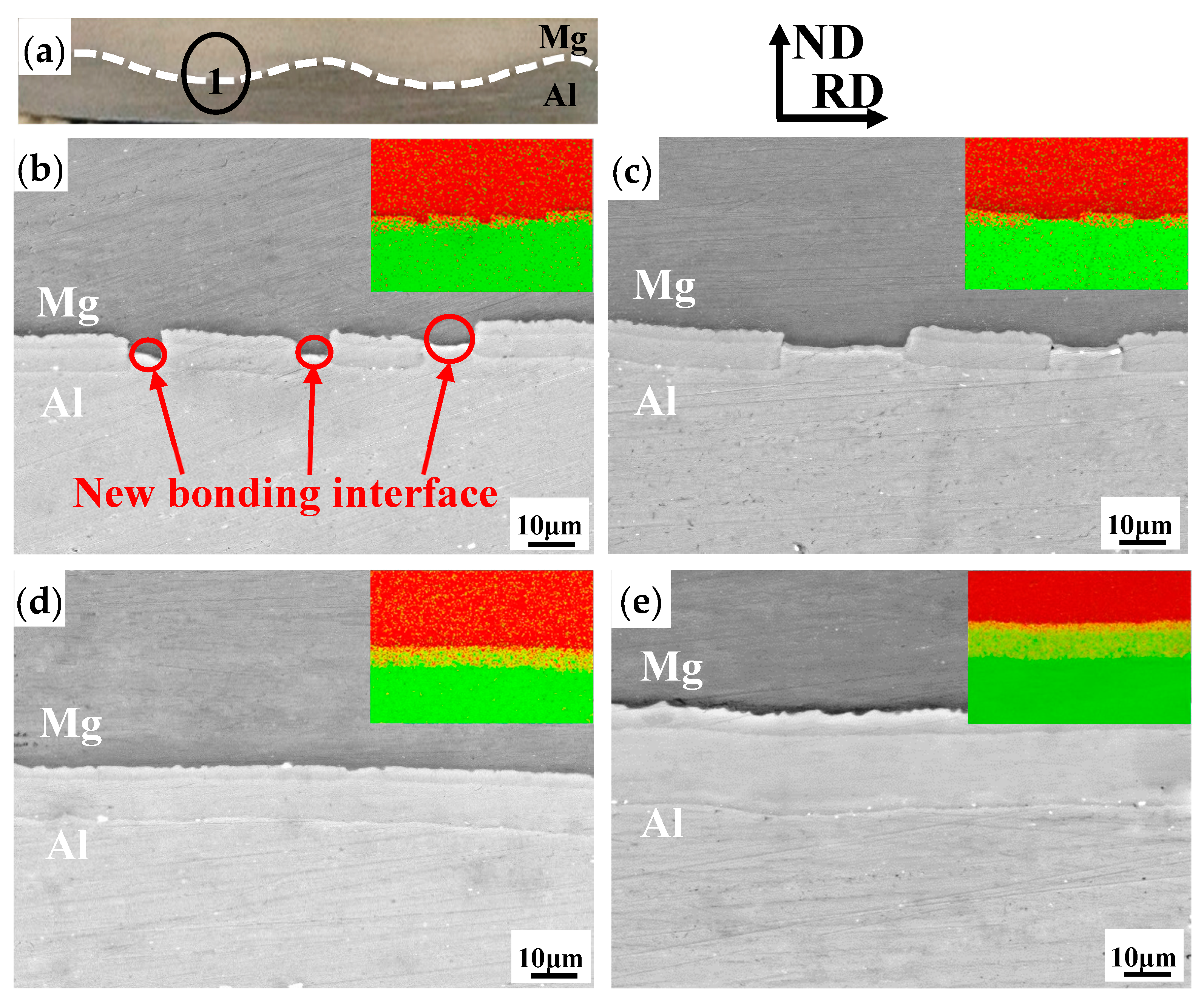
The IMC layer is discontinuous along the longitudinal direction while being continuous along the transverse direction for the flattened as-rolled sample. The spatial distribution of the microstructure can be observed along the thickness and rolling direction for magnesium alloy and aluminum alloy after the CFR process.
(3)
The Mg/Al laminated composites prepared by CFR exhibit outstanding tensile properties along both RD and TD, which can be attributed to the microstructure refinement induced by the severe shear strain. Mg/Al composites produced by CFR not only result in a reduction in the longitudinal tensile properties, but also greatly improves the transverse tensile properties.
(4)
The tensile properties along TD are higher than that along RD in both the as-rolled and heat-treated state, and this significant anisotropy of the tensile property is mainly owed to the microstructure spatial distribution and the IMC’s layer along the different directions.

Author Contributions

Conceptualization: T.W.; writing—original draft: S.L.; investigation: Z.R.; formal analysis: Y.J.; software: X.M. and W.F.; methodology: M.G.; writing—review and editing: J.H.

Funding

This study was financially supported by Major Program of National Natural Science Foundation of China (no. U1710254); Shanxi Province Science and Technology major projects (no. MC2016-01, no. 20181101008); Natural Science Foundation of Shanxi Province (no. 201701D121078, no. 201701D221143, no. 201801D221221); Key Projects of Shanxi Province Key Research and Development Plan (no. 201703D111003); Taiyuan City Science and Technology major projects (no. 170203); Scientific and Technological Progress of Shanxi Province Colleges and Universities (no. 2017132); the National Natural Science Foundation of China (no. 51804215); and the China Postdoctoral Science Foundation (no. 2018M641681).

Conflicts of Interest

The authors declare no conflict of interest.

References

  1. Wasekar, N.P.; Latha, S.M.; Ramakrishna, M.; Rao, D.S.; Sundararajan, G. Pulsed electrodeposition and mechanical properties of Ni-W/SiC nano-composite coatings. Mater. Des. 2016, 112, 140–150. [Google Scholar] [CrossRef]
  2. Li, X.B.; Zu, G.Y.; Wang, P. High strain rate tensile performance and microstructural evolution of Al/Cu laminated composite under dynamic loading. Mater. Sci. Eng. A 2014, 612, 89–95. [Google Scholar] [CrossRef]
  3. Kim, I.K.; Hong, S.I. Effect of heat treatment on the bending behavior of tri-layered Cu/Al/Cu composite plates. Mater. Des. 2013, 47, 590–598. [Google Scholar] [CrossRef]
  4. Ahledel, N.; Schulz, R.; Gariepy, M.; Hermawan, H.; Alamdari, H. Electrochemical corrosion behavior of Fe3Al/TiC and Fe3Al-Cr/TiC coatings prepared by HVOF in NaCl solution. Metals 2019, 9, 437. [Google Scholar] [CrossRef]
  5. Chen, L.; Fu, Y.; Yin, F.; Liu, N.; Liang, C. Microstructure and mechanical properties of Mg/Al clad bars with Ni interlayer processed by compound castings and multi-pass caliber rolling. Metals 2018, 8, 704. [Google Scholar] [CrossRef]
  6. Romberg, J.; Freudenberger, J.; Watanabe, H.; Scharnweber, J.; Eschke, A.; Kühn, U.; Klauß, H.; Oertel, C.-G.; Skrotzki, W.; Eckert, J.; et al. Ti/Al multi-layered sheets: Differential speed rolling (part b). Metals 2016, 6, 31. [Google Scholar] [CrossRef]
  7. Priel, E.; Ungarish, Z.; Navi, N.U. Co-extrusion of a Mg/Al composite billet: A computational study validated by experiments. J. Mater. Process. Technol. 2016, 236, 103–113. [Google Scholar] [CrossRef]
  8. Tabei, A.; Li, D.S.; Lavender, C.A.; Garmestani, H. Investigation of precipitate refinement in Mg alloys by an analytical composite failure model. Mech. Mater. 2015, 89, 59–71. [Google Scholar] [CrossRef] [Green Version]
  9. Qi, Z.C.; Yu, C.; Xiao, H. Microstructure and bonding properties of magnesium alloy AZ31/CP-Ti clad plates fabricated by rolling bonding. J. Manuf. Process. 2018, 32, 175–186. [Google Scholar] [CrossRef]
  10. Nemcko, M.J.; Qiao, H.; Wu, P.D.; Wilkinson, D.S. Effects of void fraction on void growth and linkage in commercially pure magnesium. Acta Mater. 2016, 113, 68–80. [Google Scholar] [CrossRef]
  11. Yang, M.; Liu, X.B.; Zhang, Z.Y.; Song, Y.L. Stress corrosion behavior of AM50Gd magnesium alloy in different environments. Metals 2019, 9, 616. [Google Scholar] [CrossRef]
  12. Liu, X.W.; Sun, J.K.; Zhou, F.Y.; Yang, Y.H.; Chang, R.C.; Qiu, K.J.; Pu, Z.J.; Li, L.; Zheng, Y.F. Micro-alloying with Mn in Zn–Mg alloy for future biodegradable metals application. Mater. Des. 2016, 94, 95–104. [Google Scholar] [CrossRef]
  13. Jiang, M.G.; Yan, H.; Chen, R.S. Microstructure, texture and mechanical properties in an as-cast AZ61 Mg alloy during multi-directional impact forging and subsequent heat treatment. Mater. Des. 2015, 87, 891–900. [Google Scholar] [CrossRef]
  14. Mishra, R.R.; Sharma, A.K. On mechanism of in-situ microwave casting of aluminium alloy 7039 and cast microstructure. Mater. Des. 2016, 112, 97–106. [Google Scholar] [CrossRef]
  15. Simar, A.; Bréchet, Y.; de Meester, B.; Denquin, A.; Gallais, C.; Pardoen, T. Integrated modeling of friction stir welding of 6xxx series Al alloys: Process, microstructure and properties. Prog. Mater. Sci. 2012, 57, 95–183. [Google Scholar] [CrossRef] [Green Version]
  16. Cui, H.; Tao, K.; Zhou, X.; Zhang, J. Thermal stability of nanostructured NiCrC coating prepared by HVAF spraying of cryomilled powders. Rare Met. 2008, 27, 418–424. [Google Scholar] [CrossRef]
  17. Nie, H.H.; Liang, W.; Chen, H.S.; Zheng, L.W.; Chi, C.Z.; Li, X.R. Effect of annealing on the microstructures and mechanical properties of Al/Mg/Al laminates. Mater. Sci. Eng. A 2018, 732, 6–13. [Google Scholar] [CrossRef]
  18. Nie, H.H.; Liang, W.; Zheng, L.W.; Ren, X.X.; Chi, C.Z. The microstructure, texture and mechanical properties of the rolled Al/Mg/Al clad sheets. J. Mater. Eng. Perform. 2016, 25, 4695–4705. [Google Scholar] [CrossRef]
  19. Zhang, N.; Wang, W.X.; Cao, X.Q.; Wu, J.Q. The effect of annealing on the interface microstructure and mechanical characteristics of AZ31B/AA6061 composite plates fabricated by explosive welding. Mater. Des. 2015, 65, 1100–1109. [Google Scholar] [CrossRef]
  20. Chen, Z.Q.; Wang, D.Y.; Cao, X.Q.; Yang, W.W.; Wang, W.X. Influence of multi-pass rolling and subsequent annealing on the interface microstructure and mechanical properties of the explosive welding Mg/Al composite plates. Mater. Sci. Eng. A 2018, 723, 97–108. [Google Scholar] [CrossRef]
  21. Liu, W.S.; Long, L.P.; Ma, Y.Z.; Wu, L. Microstructure evolution and mechanical properties of Mg/Al diffusion bonded joints. J. Alloy. Compd. 2015, 643, 34–39. [Google Scholar] [CrossRef]
  22. Tang, J.W.; Chen, L.; Zhao, G.Q.; Zhang, C.S.; Yu, J.Q. Study on Al/Mg/Al sheet fabricated by combination of porthole die co-extrusion and subsequent hot rolling. J. Alloy. Compd. 2019, 784, 727–738. [Google Scholar] [CrossRef]
  23. Abbasi, M.; Sajjadi, S.A. Mechanical properties and interface evaluation of Al/AZ31 multilayer composites produced by ARB at different rolling temperatures. J. Mater. Eng. Perform. 2018, 27, 3508–3520. [Google Scholar] [CrossRef]
  24. Ebrahimi, S.H.S.; Dehghani, K.; Aghazadeh, J.; Ghasemian, M.B.; Zangeneh, S. Investigation on microstructure and mechanical properties of Al/Al-Zn-Mg–Cu laminated composite fabricated by accumulative roll bonding (ARB) process. Mater. Sci. Eng. A 2018, 718, 311–320. [Google Scholar] [CrossRef]
  25. Shimoyama, K.; Yokoyama, S.; Kaneko, S.; Fujita, F. Effect of grooved roll profiles on microstructure evolutions of AZ31 sheets in Periodical Straining Rolling process. Mater. Sci. Eng. A 2014, 611, 58–68. [Google Scholar] [CrossRef]
  26. Luo, C.Z.; Liang, W.; Chen, Z.Q.; Zhang, J.J.; Chi, C.Z.; Yang, F.Q. Effect of high temperature annealing and subsequent hot rolling on microstructural evolution at the bond-interface of Al/Mg/Al alloy laminated composites. Mater. Charact. 2013, 84, 34–40. [Google Scholar] [CrossRef]
  27. Wang, T.; Li, S.; Ren, Z.; Han, J.; Huang, Q. A novel approach for preparing Cu/Al laminated composite based on corrugated roll. Mater. Lett. 2019, 234, 79–82. [Google Scholar] [CrossRef]
  28. Wang, H.; Su, L.H.; Yu, H.L.; Lu, C.; Tieu, A.K.; Liu, Y.; Zhang, J. A new finite element model for multi-cycle accumulative roll-bonding process and experiment verification. Mater. Sci. Eng. A 2018, 726, 93–101. [Google Scholar] [CrossRef] [Green Version]
  29. Liu, N.; Chen, L.; Fu, Y.; Zhang, Y.; Tan, T.; Yin, F.; Liang, C. Interfacial characteristic of multi-pass caliber-rolled Mg/Al compound castings. J. Mater. Process. Technol. 2019, 267, 196–204. [Google Scholar] [CrossRef]
  30. Mirzadeh, H.; Roostaei, M.; Parsa, M.H.; Mahmudi, R. Rate controlling mechanisms during hot deformation of Mg–3Gd–1Zn magnesium alloy: Dislocation glide and climb, dynamic recrystallization, and mechanical twinning. Mater. Des. 2015, 68, 228–231. [Google Scholar] [CrossRef]
  31. Eizadjou, M.; Danesh Manesh, H.; Janghorban, K. Mechanism of warm and cold roll bonding of aluminum alloy strips. Mater. Des. 2009, 30, 4156–4161. [Google Scholar] [CrossRef]
  32. Hosseini, S.A.; Hosseini, M.; Danesh Manesh, H. Bond strength evaluation of roll bonded bi-layer copper alloy strips in different rolling conditions. Mater. Des. 2011, 32, 76–81. [Google Scholar] [CrossRef]
  33. Yousefi Mehr, V.; Toroghinejad, M.R.; Rezaeian, A. The effects of oxide film and annealing treatment on the bond strength of Al–Cu strips in cold roll bonding process. Mater. Des. 2014, 53, 174–181. [Google Scholar] [CrossRef]
  34. Jia, W.; Ma, L.; Le, Q.; Zhi, C.; Liu, P. Deformation and fracture behaviors of AZ31B Mg alloy at elevated temperature under uniaxial compression. J. Alloy. Compd. 2019, 783, 863–876. [Google Scholar] [CrossRef]
  35. Wang, H.Y.; Feng, T.T.; Zhang, L.; Liu, C.G.; Pan, Y.; Zha, M.; Nan, X.L.; Wang, C.; Jiang, Q.C. Achieving a weak basal texture in a Mg–6Al–3Sn alloy by wave-shaped die rolling. Mater. Des. 2015, 88, 157–161. [Google Scholar] [CrossRef]
  36. Timmermans, G.; Froyen, L. Tribological performance of hypereutectic P/M Al–Si during sliding in oil. Wear 1999, 231, 77–88. [Google Scholar] [CrossRef]
  37. Lee, K.S.; Yoon, D.H.; Kim, H.K.; Kwon, Y.-N.; Lee, Y.-S. Effect of annealing on the interface microstructure and mechanical properties of a STS–Al–Mg 3-ply clad sheet. Mater. Sci. Eng. A 2012, 556, 319–330. [Google Scholar] [CrossRef]
  38. Straumal, B.B.; Dobatkin, S.V.; Rodin, A.O.; Protasova, S.G.; Mazilkin, A.A.; Goll, D.; Baretzky, B. Structure and properties of nanograined Fe-C alloys after severe plastic deformation. Adv. Eng. Mater. 2011, 13, 463–469. [Google Scholar] [CrossRef]
  39. Brennan, S.; Bermudez, K.; Kulkarni, N.S.; Sohn, Y. Interdiffusion in the Mg-Al system and intrinsic diffusion in β-Mg2Al3. Metall. Mater. Trans. A 2012, 43, 4043–4052. [Google Scholar] [CrossRef]
  40. Negendank, M.; Mueller, S.; Reimers, W. Coextrusion of Mg–Al macro composites. J. Mater. Process. Technol. 2012, 212, 1954–1962. [Google Scholar] [CrossRef]
  41. Macwan, A.; Jiang, X.Q.; Li, C.; Chen, D.L. Effect of annealing on interface microstructures and tensile properties of rolled Al/Mg/Al tri-layer clad sheets. Mater. Sci. Eng. A 2013, 587, 344–351. [Google Scholar] [CrossRef]
  42. Chen, L.; Tang, J.; Zhao, G.; Zhang, C.; Chu, X. Fabrication of Al/Mg/Al laminate by a porthole die co-extrusion process. J. Mater. Process. Technol. 2018, 258, 165–173. [Google Scholar] [CrossRef]
  43. Mazilkin, A.A.; Straumal, B.B.; Borodachenkova, M.V.; Valiev, R.Z.; Kogtenkova, O.A.; Baretzky, B. Gradual softening of Al–Zn alloys during high-pressure torsion. Mater. Lett. 2012, 84, 63–65. [Google Scholar] [CrossRef]
  44. Straumal, B.B.; Kilmametov, A.R.; Ivanisenko, Y.; Mazilkina, A.A.; Kogtenkova, O.A.; Kurmanaeva, L.; Korneva, A.; Zieba, P.; Baretzky, B. Phase transitions induced by severe plastic deformation: Steady-state and equifinality. Int. J. Mater. Res 2015, 106, 657–664. [Google Scholar] [CrossRef]
  45. Haghdadi, N.; Zarei-Hanzaki, A.; Abou-Ras, D. Microstructure and mechanical properties of commercially pure aluminum processed by accumulative back extrusion. Mater. Sci. Eng. A 2013, 584, 73–81. [Google Scholar] [CrossRef]
  46. Cui, N.; Wu, Q.; Wang, J.; Lv, B.; Kong, F. The directional solidification, microstructural characterization and deformation behavior of beta-solidifying TiAl alloy. Materials 2019, 12, 1203. [Google Scholar] [CrossRef]
  47. Kudo, S.; Yokoyama, S.; Shimoyama, K.; Kaneko, S.; Fujita, F. Effect of dimple patterning conditions of Periodical Straining Rolling on microstructures and mechanical properties of AZ31 sheets. Mater. Sci. Eng. A 2017, 680, 75–84. [Google Scholar] [CrossRef]
  48. Chen, S.X.; Li, W.G.; Liu, X.H. Calculation of rolling pressure distribution and force based on improved Karman equation for hot strip mill. Int. J. Mech. Sci. 2014, 89, 256–263. [Google Scholar] [CrossRef]
  49. Nie, H.; Liang, W.; Yang, F.; Zheng, L.; Li, X.; Fan, H. Texture Evolution of Single-Pass Hot-Rolled 5052/AZ31/5052 Clad Sheets. JOM 2016, 68, 2274–2287. [Google Scholar] [CrossRef]
  50. Lee, K.S.; Kim, J.S.; Jo, Y.M.; Lee, S.E.; Heo, J.; Chang, Y.W.; Lee, Y.S. Interface-correlated deformation behavior of a stainless steel-Al–Mg 3-ply composite. Mater. Charact. 2013, 75, 138–149. [Google Scholar] [CrossRef]
Figure 1. Schematic diagram of the CFR method and actual Mg/Al laminated composite: (a) Schematic diagram of the CFR method; (b) the corrugated sample after the first CFR pass; and (c) the flattened composite after the second CFR pass.
Metals 09 00690 g001
Figure 2. Metallographic microstructure (a) and grain size diagram (b) of AZ31B after heat treatment at 400 °C for 15 min.
Metals 09 00690 g002
Figure 3. Schematic diagram of numerical simulation for the corrugated rolling process.
Metals 09 00690 g003
Figure 4. SEM images of the bonding interface and OM images of the AZ31B near the corrugated roll for the corrugated composite: (a,c,e) peak position; and (b,d,f) trough position.
Metals 09 00690 g004
Figure 5. Numerical simulation results of the first CFR pass: (a) PEEQ nephogram in the initial stage of rolling; (b) PEEQ nephogram during the first corrugated roll process; (c) PEEQ histogram; and (d) the true stress-strain curve of AZ31B under 5 s−1 strain rate at 400 °C.
Metals 09 00690 g005
Figure 6. SEM micrographs of the intermediate heating process at 400 °C for 5 min: (a,c) RD; (b,d) TD.
Metals 09 00690 g006
Figure 7. SEM images and elemental scanning distribution of CFR flattened samples along RD: (a) Selected location schematic; (b) as-rolled; (c) 200 °C; (d) 300 °C; and (e) 350 °C.
Metals 09 00690 g007
Figure 8. Line scan distribution of the annealed samples: (a) As-rolled; (b) 200 °C; (c) 300 °C; and (d) 350 °C.
Metals 09 00690 g008
Figure 9. SEM images and elemental surface scanning for CFR flattened Mg/Al laminated composite along TD: (a) As-rolled; (b) 200 °C; (c) 300 °C; and (d) 350 °C.
Metals 09 00690 g009
Figure 10. Microstructure of the AZ31B of as-rolled CFR Mg/Al laminated composite. (ac) Position 1; and (df) position 2.
Metals 09 00690 g010
Figure 11. Microstructure of the 5052 of as-rolled CFR Mg/Al laminated composite. (ac) Position 3; and (df) position 4.
Metals 09 00690 g011
Figure 12. Schematic illustration showing the shear stress during the CFR process.
Metals 09 00690 g012
Figure 13. The engineering stress-strain curves and histograms of the flattened samples: (a,b) RD; (c,d) TD.
Metals 09 00690 g013
Figure 14. Fracture diagrams of flattened samples: (ad) RD, (eh) TD. (a,e) As-rolled; (b,f) 200 °C; (c,g) 300 °C; (d,h) 350 °C.
Metals 09 00690 g014
Table 1. Measured chemical compositions (in wt%) of AZ31B and 5052.
MaterialsMgCuCaMnSiAlZnCrFe
AZ31BRest0.010.040.80.073.21.2--
50522.2–2.80.10-0.100.25Rest0.100.15–0.350.4
Table 2. Chemical composition in different regions of Figure 6a via EDS analysis.
MaterialsMg (at%)Al (at%)IMCs
A59.9 ± 440.1 ± 4Mg17Al12
B38.2 ± 361.8 ± 3Mg2Al3

