Article

New Ferritic Stainless Steel for Service Temperatures up to 1050 °C Utilizing Intermetallic Phase Transformation

1
Materials and Mechanical Engineering, Faculty of Technology, University of Oulu, P.O. Box 4200, 90014 Oulu, Finland
2
Outokumpu, Process R&D, 95490 Tornio, Finland
*
Author to whom correspondence should be addressed.
Metals 2019, 9(6), 664; https://doi.org/10.3390/met9060664
Submission received: 25 April 2019 / Revised: 4 June 2019 / Accepted: 5 June 2019 / Published: 7 June 2019
(This article belongs to the Special Issue Manufacturing and Application of Stainless Steels)

Abstract

:
A large number of thermodynamic simulations has been used to design a new Nb-Ti dual stabilized ferritic stainless steel with excellent creep resistance at 1050 °C through an optimal volume fraction of Laves (η) phase stabilized by the alloying elements Nb, Si and Mo. By raising the dissolution temperature of the phase, which also corresponds to the onset of rapid grain growth, the steel will better maintain the mechanical properties at higher service temperature. Laves phase precipitates can also improve creep resistance through precipitation strengthening and grain boundary pinning depending on the dominant creep mechanism. Sag tests at high temperatures for the designed steel showed significantly better results compared to other ferritic stainless steels typically used in high temperature applications at present.

Graphical Abstract

1. Introduction

Stainless steel is used for many different automobile components due to its excellent corrosion and heat resistance, good appearance and mechanical properties. The use of stainless steel in automobile manufacture began with decorative trims, but has since spread into more functional components, such as exhaust systems, where stainless steel accounts for more than half of all the stainless steel used in automotive applications [1,2,3]. The increased use of stainless steel in exhaust systems has been result of tightening exhaust gas regulations and producer warranties together with the desire to decrease fuel consumption and vehicle weight. Those parts of the exhaust system closest to the engine are exposed to the highest service temperatures and are therefore the most demanding as regards properties. For the hot end of the exhaust system, high-Cr ferritic stainless steels have been introduced instead of more commonly used AISI 409 or 304 steels. However, these steels lack the properties needed to be used above 850 °C, i.e. nearest to the engine, where the material is required to have excellent high-temperature strength, together with resistance to thermal fatigue, oxidation and corrosion. Such a component is for example the exhaust manifold, which is directly attached to the engine and susceptible to temperatures up to 1050 °C [1,2,3,4,5,6,7]. The austenitic stainless steel AISI 304 has excellent high-temperature strength but weak cyclic oxidation resistance, while the ferritic stainless steel AISI 409 has inferior high-temperature strength. To replace these, a Nb-Ti-stabilized ferritic stainless steel with 18% chromium, i.e. AISI 441, was introduced and is currently used because of its better high temperature properties compared to AISI 409. AISI 441 can be used at temperatures up to 950 °C, but still does not meet the full requirements of modern exhaust systems [5]. In the current study, the authors show how a new type of ferritic stainless steel with 21% chromium and a relatively high Nb content has been designed with the aim of meeting these increasing requirements by being usable even at 1050 °C with the aid of precipitation. Potential precipitate phases stable above 700 °C are Laves (η) and Chi (χ), which are typically encountered in high-temperature applications [8]. Provided the precipitates are small enough, these phases can increase both the ambient and high-temperature strength of the steel via precipitation strengthening [9]. In addition, such precipitates may increase creep resistance as is common in martensitic pipeline steels [10,11,12]. However, in ferritic stainless steels the precipitation of intermetallic phases to improve creep resistance is not widely exploited [13,14,15,16].
In this research, the authors design a new dual stabilized ferritic stainless steel with enhanced creep resistance compared to conventional High-Cr ferritic stainless steels used in high temperature applications. The improvement of creep resistance is achieved by utilizing the precipitation of η-phase and by controlling the amount, nucleation site and the solvus temperature of the phase. η-phase is an intermetallic AB2 type phase such as Fe2Nb and Fe2Ti, but sometimes including other alloying elements, for e.g. Si, Cr or Mo. η-phase has a hexagonal crystal structure with c/a ratio of approximately 1.633 with unit cells in the range of a = 0.473–0.495 nm and c = 0.770–0.815 nm [17,18]. The distribution of the η-phase in the microstructure can influence the high temperature mechanical properties of the steel. The creep resistance can be improved whether the η-phase is on the grain boundaries or within the grains depending on the creep mechanism and η-phase amount and particle size. The nucleation of η-phase in α-Fe based alloys has been observed to first occur at the grain boundaries, then on dislocations and finally in the α-Fe matrix [19]. The η-phase amount and solvus temperature limits the service temperature of the steel but can be controlled by carefully balancing the alloying elements included in η-phase, such as Nb, assuming there is no nucleation of interfering Nb containing precipitates [16]. In addition, the nucleation site of the η-phase can be controlled by applying precise annealing parameters such as the peak temperature and holding time.

2. Methodology

2.1. Thermo-Calc and TC-Prisma
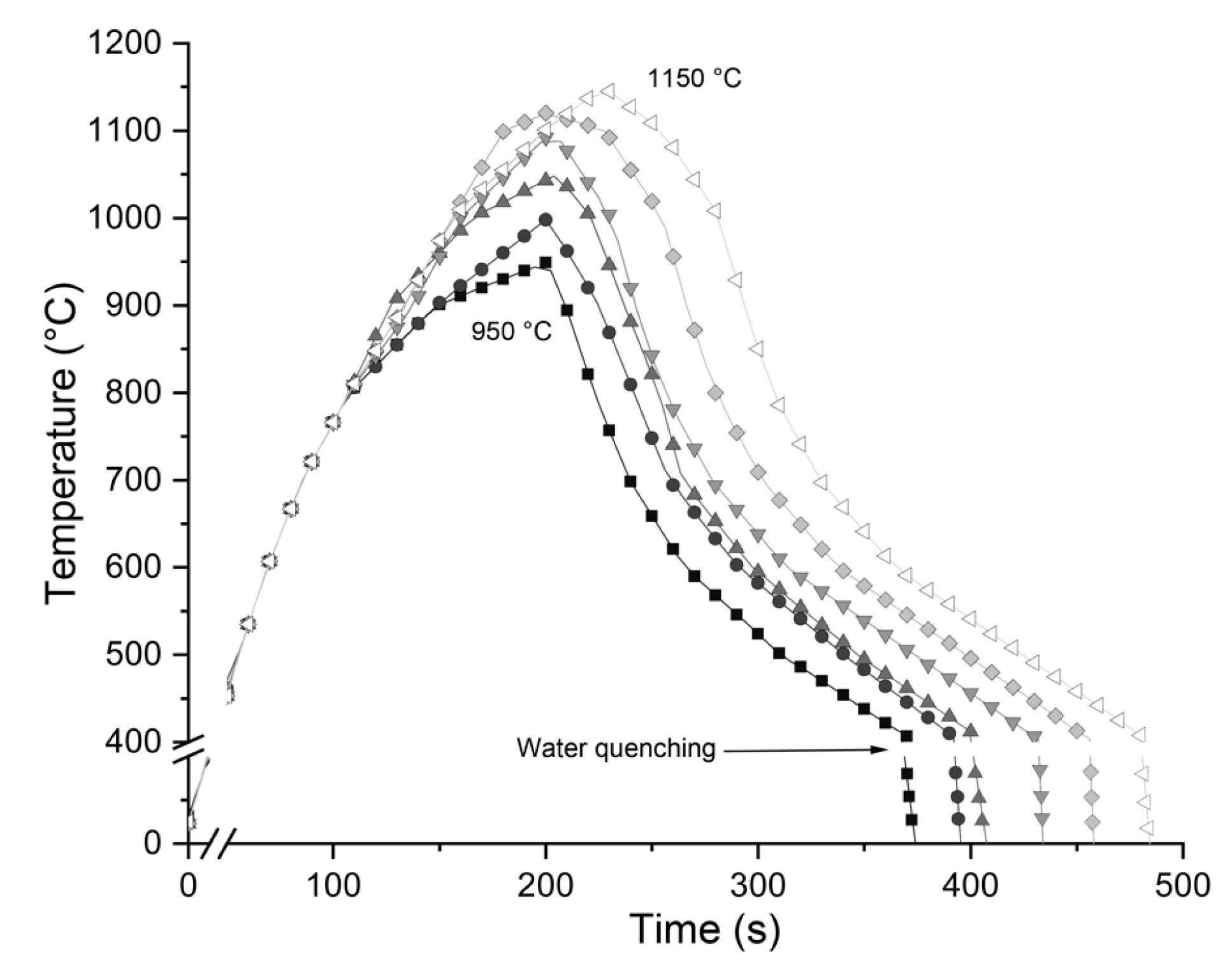
To help in the selection of an optimal composition for a trial steel a comprehensive set of thermodynamic simulations has been carried out using TC-Prisma software together with the Thermo-Calc thermodynamic database for Fe-based alloys TCFE9 and the atomic mobility database for Fe-based alloys MOBFE2 [20]. TC-Prisma simulates the diffusion controlled nucleation, growth and dissolution of precipitates using the Langer-Schwartz theory and the Kampmann-Wagner numerical approach in conjunction with Thermo-Calc and its diffusion controlled phase transformation module (DICTRA). In TC-Prisma the classic nucleation theory has been extended to model nucleation in multicomponent alloy systems [21]. The classic nucleation theory describes the time dependent nucleation rate defined as:
J ( t ) = J s exp ( τ t ) ,
where Js is the steady state nucleation rate, τ is the incubation time for establishing steady state nucleation conditions, and t is the isothermal reaction time. The steady state nucleation rate is given by:
J s = Z β * N 0 exp ( Δ G * k T ) ,
where Z is the Zeldovich factor, a measure of the probability with which an embryo with a radius slightly larger than the critical radius passes back across the free energy barrier thereby dissolving in the matrix, β* is the rate at which atoms attach to the critical nucleus, N0 is the number of nucleation sites per unit volume, ΔG* is the Gibbs energy for the formation of a critical nucleus, k is Boltzmann’s constant and T is the absolute temperature. The number of nucleation sites depends on the shape and size of the grains. Assuming all grains are of equal size tetrakaidekahedral, the density for the grain boundary area per unit volume is calculated as:
ρ = 6 1 + 2 A 2 + 1 + 2 A 4 A D 1 ,
where A is the aspect ratio (1 by default) and D is the distance between one pair of hexagonal faces. Assuming boundary thickness as one atomic layer, the number of nucleation sites is:
N = ρ ( N A V m α ) 2 / 3 ,
where Vmα is the molar volume of the matrix phase and NA is the Avogadro number. The Gibbs energy required for the formation of critical nucleus is expressed as:
Δ G * = 16 π σ 3 3 ( Δ G m α β /   V m β   ) 2 ,
where σ is the interfacial energy, ΔGmα→β is the molar driving force for the formation of a β precipitate from the α matrix and Vmβ is the molar volume of the β precipitate phase. Interfacial energy σ is calculated with an extended Becker’s model using thermodynamic data from the existing CALPHAD thermodynamic database and can be described as:
σ = n s z s n A z l Δ E s ,
where ns is the number of atoms per unit area at the interface, zs is the number of bonds per atom crossing the interface, zl is the coordination number of an atom within the bulk crystal lattice, and ΔEs is the energy of solution in a multicomponent system involving the two phases being considered [21].

2.2. Sag Tests

Bars with dimensions of 150 × 15 × 2 mm were cut for a simple high-temperature sag tests as illustrated in Figure 1. This is a simple test to evaluate high-temperature creep resistance. The bars were placed horizontally in a furnace with both ends supported 20 mm above the bottom of the furnace. The distance between the supports was L = 140 mm. After holding the sample in the furnace at temperatures in the range 800 to 1050 °C for 20 or 100 h, the deflection of the bars is measured. The creep deformation is caused by the sample’s own weight and is heavily reliant on the bar dimensions. Hence, the dimensions, furnace and other conditions are kept constant throughout the test for all samples. The active creep mechanism in the sag test can be estimated using the deformation map in which the different creep mechanisms are located in normalized stress - temperature space.
The creep mechanisms considered are power-law or dislocation creep, and the diffusional creep mechanisms known as Coble creep and Nabarro-Herring creep [22,23]. The stress state in the sag test can be estimated using classical beam theory. The specimen is then modelled as a simply supported beam. The problem is statically determinate, and therefore the distribution of bending moment can be determined directly based on equilibrium equations. In the beginning of the test, the cumulated inelastic strain is negligible, and the distribution of axial normal stress may be assumed linear over the thickness of the specimen. The maximum shear stress exists in the center point between the supports, on the upper and lower surfaces, and is given by:
τ max = ( 3 8 ) ρ g L 2 t ,
where ρ is the density of the material, g acceleration of gravity, L distance between the supporting points and t the thickness of the specimen. The origin of the coordinate system is positioned in the middle plane of the specimen on the leftmost supporting point. The maximum shear stress has the value of τmax = 0.28 MPa. The shear modulus as a function of temperature can be approximated as:
μ ( T ) = μ o d μ d T Δ T ,
where dμ/dT is −37.3 [MPa/K] and the shear modulus at 300 K (μ0) is 78 GPa [24,25]. Therefore, the shear stress normalized with respect to the shear modulus is 7.0 × 10⁻⁶ at 1050 °C and the homologous temperature, T/Tm, where Tm is the absolute melting temperature, is 0.7.

3. Results

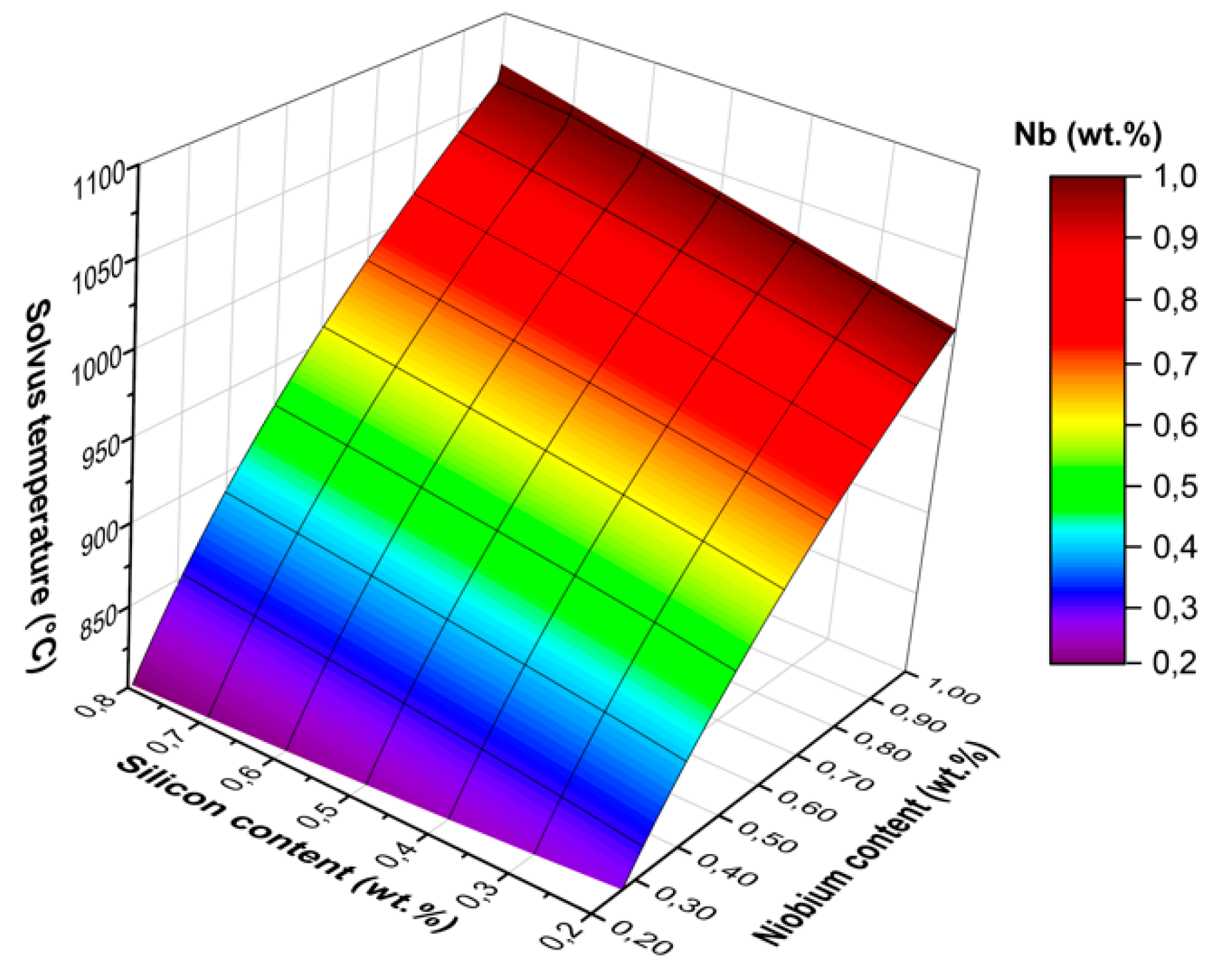
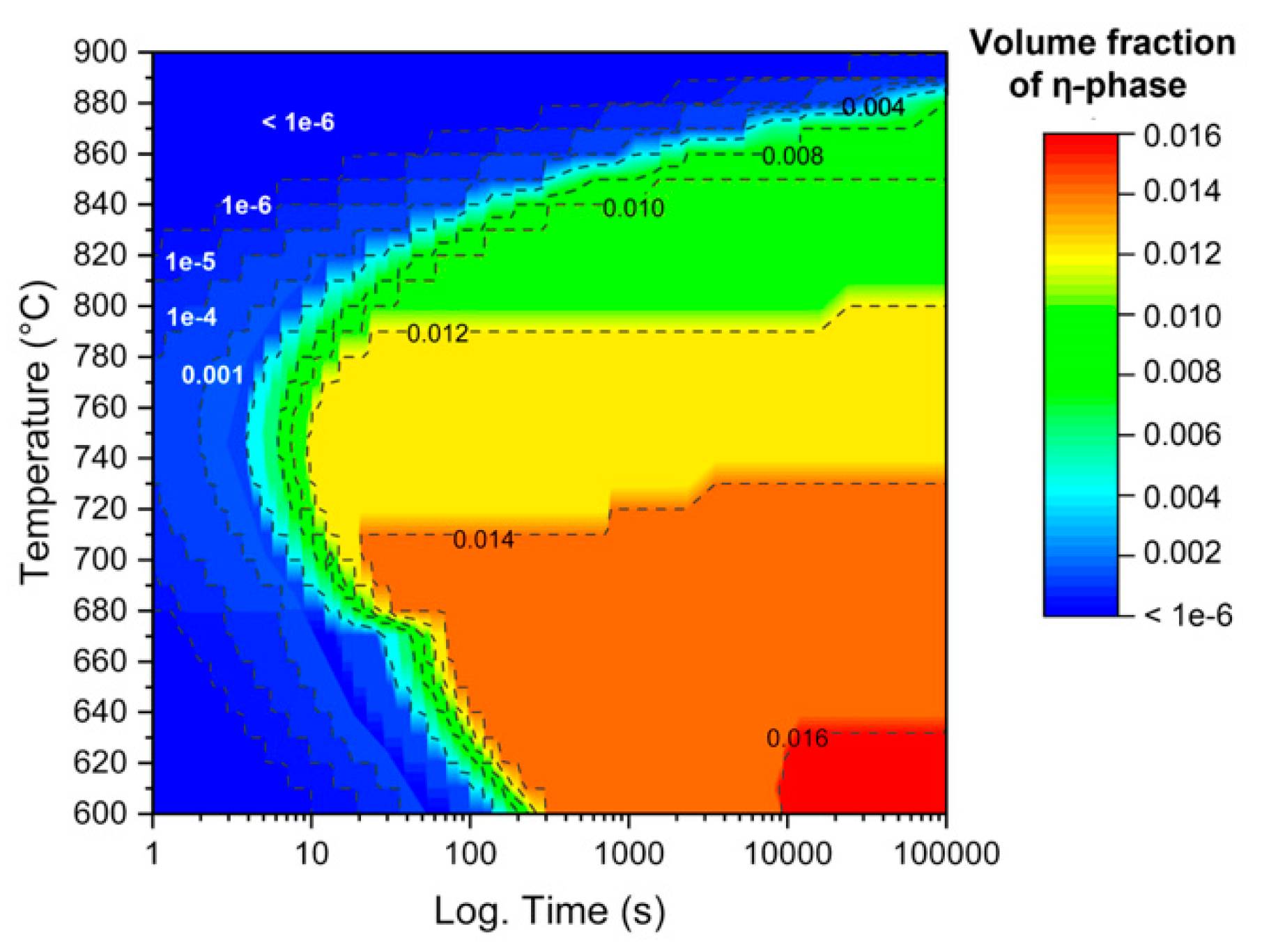
3.1. Thermodynamic Simulations

TC-Prisma and Thermo-Calc was used to simulate solvus temperature, equilibrium volume fraction and precipitation kinetics of η-phase in fixed base composition (0.02C-0.02N-21Cr-0.32Mn-0.2Ti wt.%) with Nb content in a range of between 0.2 and 1.0 wt.%, Si between 0.2 and 0.8 wt.%, and Mo between 0.03 wt.% and 2.0 wt.%. The interfacial energy for the simulations was calculated with the modified Becker’s model to be between 0.14 and 0.16 J/m2 in the temperature range of 400 °C to 1000 °C. Nucleation was assumed to take place at the grain boundaries with grain size of 50 μm (5.7 ASTM) used for the simulations. According to the simulation results shown in Figure 2, alloying with Nb increases the solvus temperature of η-phase and therefore the temperature in which the grain growth begins, ultimately affecting the service temperature of the steel as shown by Nabiran et al. in the case of Fe2Nb type η-phase [26].
A similar effect to that achieved with Nb is also achieved by alloying with Si, however, to a significantly smaller degree. According to the thermodynamic simulations, increasing the Si content from 0.4 to 0.8 wt.% increases the solvus temperature of η-phase by approximately 30 °C, whereas increasing the Nb content by 0.4 wt.% would result in an increase of 100 to 150 °C within the range of 0.35 and 1 wt.% of Nb, as shown in Figure 2. Ferritic stainless steels typically contain significantly larger amounts of Mo than Nb and Si, for e.g. type AISI 444 contains 2 wt.% of Mo. The thermodynamic simulation results suggest that Mo alloying does not have a significant effect on the η-phase solvus temperature as seen in Figure 3. Therefore, it was decided to omit Mo alloying. However, Mo can increase the volume fraction of η-phase and Mo alloying could be considered if the amount of η-phase in the microstructure is insufficient to increase creep resistance.
Concerning the optimization of Ti in the steel, the precipitation of Ti containing carbonitrides at very high temperatures during casting must be considered. The amount of Ti should be high enough to deplete the microstructure of free C and N so no Nb containing carbonitrides form and Nb is isolated for η-phase precipitation. The ideal amount of Ti alloying is achieved when a tiny amount is precipitated in η-phase, the carbon and nitrogen level are kept as low as possible and the amount of Ti carbonitrides is high enough to deplete all free interstitials from the matrix. However, excess alloying of Ti can result in surface defects and is typically kept at 0.2 wt.% or below [27,28]. When alloying 0.2 wt.% Ti to a steel containing 0.02C-0.02N-0.8Nb-0.8Si, according to Thermo-Calc the equilibrium composition of η-phase in temperatures above 850 °C is 46Nb-39Fe-11Cr-3Si-0.4Ti in wt.%, which means most of the Ti has precipitated as carbonitrides. Therefore 0.2 wt.% Ti can be considered very close to optimal.

3.2. Annealing Microstructures

Based on the results of the thermodynamic simulations and the criteria given above, a trial steel with the chemical composition 0.02C-0.02N-0.8Nb-0.8Si-0.2Ti (wt.%) was prepared as a 65 kg laboratory cast ingot. The cast ingot was reheated to 1100 °C and held for 75 min which is typical for ferritic stainless steels, and then hot rolled with a starting temperature of 1160 °C in seven passes to an end thickness of 6 mm. This was followed by cold rolling with a 30% reduction to a thickness of 4.2 mm. The cold rolled strips were then pre-annealed and final cold rolled with 48% reduction to a final thickness of 2 mm following final annealing to achieve optimal microstructure to the finished product. Pre-annealing and final annealing were done to obtain a fully recrystallized microstructure with a low volume fraction of η-phase as described below.
The pre-annealing was simulated with Gleeble 3800 thermomechanical simulator using parameters that match typical plant-scale annealing as regards heating and cooling rates as seen in Figure 4. The temperature range of 950 °C to 1200 °C was selected for pre-annealing simulations. The isothermal precipitation diagram calculated with TC-Prisma in Figure 5 shows that 1% of η-phase is predicted to precipitate in approximately ten seconds in the temperature window 700 to 800 °C. The precipitation slows down significantly at higher temperatures due to the reduction of the driving force (ΔGmα→β) and high interfacial energy (σ) of the η-phase. Comparing the TC-Prisma predictions with the Gleeble simulation heating curves presented in Figure 4, it can be seen that a significant amount of η-phase can precipitate during the pre-annealing and some nucleation will likely occur during the cooling as well.
There are two things that need to be considered when selecting the pre-annealing peak temperature; first, the microstructure should be fully recrystallized after the annealing, and secondly, any previously precipitated η-phase should be dissolved so that it can precipitate after recrystallization for good creep resistance. The microstructure of the steel is ferritic from ambient to solvus temperature so no phase transformation apart from the precipitation will occur at any temperature.
The thermodynamic and Gleeble simulations suggest that the recrystallization temperature is in fact, also dependent on the dissolution temperature of η-phase. This dependency can be related to the pinning effect of η-phase particles at grain boundaries or to solute Nb and its decreasing effect on grain boundary mobility; however, confirmation of this is not covered in present study [29,30]. The pre-annealing temperature had to be set high enough to obtain full recrystallization and complete or almost complete η-phase dissolution. The grain size should be kept reasonably low (around ASTM 6 or smaller) by avoiding rapid grain growth in order to meet the requirements for good formability during manufacturing as well as low and high temperature strength, although larger grain size would likely increase the creep resistance. However, the grain size after pre-annealing is not significant, as the material will be later cold rolled and final annealed. Microstructures after the simulated annealing cycles were analyzed using a ZEISS Ultra+ Field Emission Scanning Electron Microscope (FESEM) and typical microstructures from each stage of the cold rolling and annealing process can be seen in Figure 6. After pre-annealing at 950 °C, the microstructure was not fully recrystallized. However, after pre-annealing at 1050 °C (Figure 6) the microstructure was recrystallized, but a high volume fraction of η-phase was present and partly distributed in rows, indicating that the pre-annealing temperature had to be even higher. The microstructure of a sample pre-annealed at 1150 °C contained no η-phase and showed that full recrystallization had occurred. However, the grain size was increased compared to that before annealing. As mentioned earlier the grain size after pre-annealing is not as significant as it is in the final, so 1150 °C was selected as the pre-annealing temperature.
The parameters for final annealing were determined using a similar approach. To get smaller grain size after final annealing, the temperature window has to be smaller compared to pre-annealing. The lowest peak temperature that resulted in full recrystallization was 1120 °C, so this was chosen for the final annealing, although some grain growth was observed, and some η-phase was still left but in very small amounts. The obtained grain size 5.0 ASTM was slightly larger than the target of 6 ASTM.

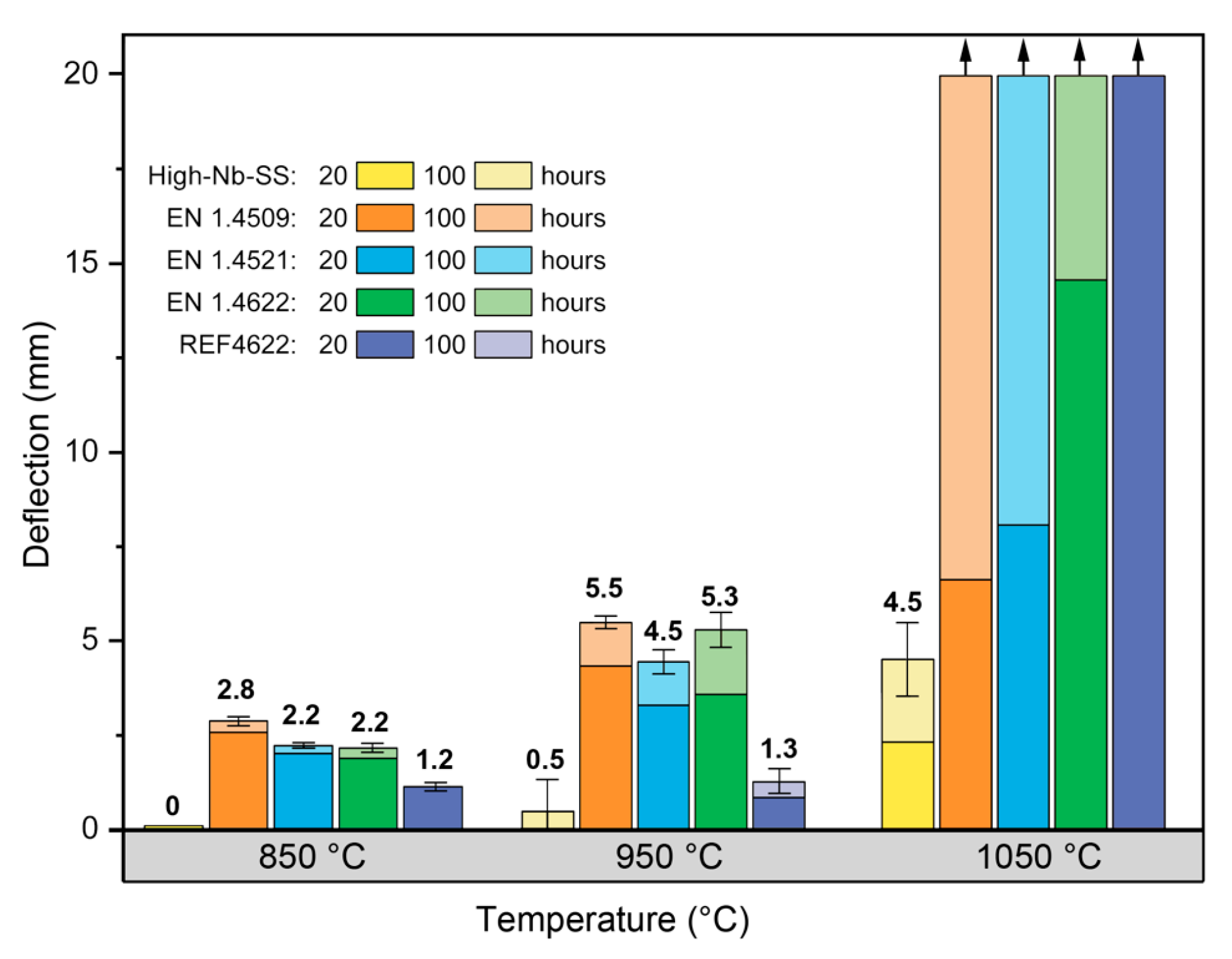
3.3. Creep Resistance

Figure 7 shows the results of the sag tests for typical stainless steel grades used in high temperature applications, the high-Nb-SS trial test material and reference material REF4622 with composition close to that of EN 1.4622 but manufactured using similar process parameters those employed here for the High-Nb-SS steel. The compositions of the steels, grain size at room temperature and solvus temperatures of η-phase can be seen in Table 1.
The High-Nb-SS steel showed significantly better sag test results, i.e. higher creep resistance in the absence of external stress, than the reference material or other stainless steel grades. At 850 °C there was no measurable sag (i.e. < 0.1 mm) for the High-Nb-SS steel during the 100 h test, and only 0.5 mm deflection was measured after testing at 950 °C. When tested at 1050 °C the High-Nb-SS steel exhibited similar deflection to that shown by the other steels at 850 °C and 950 °C.

4. Discussion

According to the deformation maps for ferritic steels by Ashby [23] and Zinkle et al. [31] and considering the calculated shear stress and homologous temperature, the dominant creep mechanism during the sag test would be Coble creep, which typically occurs at low stresses and high temperatures and is controlled by grain boundary diffusion. The creep rate in Coble creep is proportional to the stress. The linear distribution of axial normal stress will therefore prevail provided that the curvature of the specimen remains moderate. The maximum shear stress will therefore be approximately constant and Cobble creep will remain as the active deformation mechanism throughout the test in this particular case. The creep rate in Coble creep is inversely proportional to the cube of the grain size [22,32]. Another high-temperature creep mechanism in which finer grain size has negative effect is grain boundary sliding. Grain boundary sliding however is not an independent mechanism but accommodated by other creep modes and its effect can be mitigated if the grain boundaries are effectively covered with precipitates [32,33]. The overlapping of the mechanisms is discussed by Hertzberg et al. (1989) who suggest that Coble creep is dependent on grain boundary sliding [32]. Therefore, suppression of both mechanisms should be considered when designing steel with good creep resistance. The negative effect of a fine grain size on grain boundary sliding can be reduced if the grains are sufficiently covered with η-phase precipitates that act as pinning points resisting grain boundary sliding [11,34].
Figure 8 shows the η-phase precipitated along the grain boundaries and within the grains of the microstructure of a sag sample after 100 h at 950 °C as expected. The larger grain size of the trial steel compared to other steels (Table 1) can have a positive effect on creep resistance because of Coble creep mechanism [9], however, during the sag test the grain size increases in other steels resulting in larger grain size. This is result of the considerably higher solvus temperature of η-phase in High-Nb-SS, which correlates to simulated equilibrium solvus temperatures shown in Table 1. The grain growth was further observed by measuring the grain size from each sample after sag test at 950 °C for 100 h. The grain size (ASTM) in High-Nb-SS, REF4622 and EN 1.4622 was approximately 4–5, 2 in EN 1.4509 and too large to be measured in EN 1.4521 (i.e. <0 ASTM) as shown in Table 1. It seems that the negative effect of a finer grain size in High-Nb-SS steel is mitigated by the precipitation of η-phase on the grain boundaries, as previously explained.
According to Thermo-Calc simulations for equilibrium at 950 °C, the volume fractions of η, TiN and NbC are 0.6%, 0.2% and 0.1%, respectively. With simple image analysis carried out for sag tested sample using ImageJ software with 1.64 mm2 surface area and hundreds of particles, a volume fraction of 1.124% for all particles visible in a backscattered electron image was measured, i.e. η and NbC excluding TiN. FESEM image of a part of the analyzed area is shown in Figure 8. η-phase was identified with TEM diffraction image (Figure 8) to have a hexagonal C14 crystal structure with lattice parameters a = 4.27 Å and c = 7.77 Å and composition of 53Fe-25Nb-11Cr-9Si-2Ti (wt.%) measured with EDS [8,17]. The results correlate well with the Thermo-Calc predictions for the volume fraction at equilibrium state. The equilibrium composition of η-phase according to Thermo-Calc is 49Fe-32Nb-11Cr-7Si-1Ti which also correlates well with the EDS analysis.
When particles inside the grains are removed from the image (Figure 8), the volume fraction of η-phase left at grain boundaries was calculated 0.77% using the ImageJ software. The amount could be high enough to retain good creep resistance in High-Nb-SS steel even with its finer grain size under low stress–high temperature conditions. The finer grain size could be achieved by further restraining the rapid grain growth during annealing with a more optimal peak temperature. However, this would require more simulations and tests. In the sag test the dominant creep mechanism involves diffusion along grain boundaries, however, the presence of η-phase inside the grains implies that good creep resistance is also expected for higher stresses where other creep mechanisms are dominant. This needs to be examined with comprehensive creep tests. The formation of η-phase can be expected to have some influence on the mechanical properties of the steel in room temperature based on the Author’s previous studies on the effect η-phase on strengthening in AISI 444 type ferritic stainless steel [9].

5. Conclusions

1)
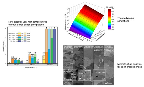
When alloying 0.8 wt.% of Nb and Si, the equilibrium solvus temperature of the η-phase in High-Nb-SS was calculated as 1026 °C. The solvus temperature is 175 °C higher than in EN1.4509 which is a commonly used steel in high temperature applications. When exposed to temperatures above the solvus temperature, the rapid grain growth begins, limiting the service temperature of the steel.
2)
The dominant creep mechanism during the sag test is Cobble creep, which is related to the grain boundary diffusion and can therefore be suppressed by grain boundary precipitation.
3)
Grain boundary precipitation of η-phase resulted in significantly lower deflections in Sag test, i.e. enhanced the creep resistance of High-Nb-SS compared to commercially available steels used in high temperatures.
4)
Creep rate in the Cobble mechanism is inversely proportional to the cube of the grain size. However, the η-phase precipitation mitigated the negative effect of a finer grain size in High-Nb-SS steel. Avoiding grain growth at higher temperature will better maintain other mechanical properties of the steel.

6. Patents

The work reported in this manuscript resulted in Patent no. 18215480.7-1103

Author Contributions

Conceptualization, T.J.; methodology, T.J. and S.U.; software, T.J.; validation, T.J. and T.M.; formal analysis, T.J., S.U. and T.M.; investigation, T.J., D.P.; resources, T.J. and T.M.; data curation, T.J.; writing—original draft preparation, T.J.; writing—review and editing, T.J., T.M. and D.P.; visualization, T.J.; supervision, D.P.; project administration, J.K.; funding acquisition, T.J., T.M. and J.K.

Funding

This research was funded by Companhia Brasileira de Metalurgia e Mineração and the Academy of Finland through the project #311943.

Acknowledgments

The authors wish to acknowledge Juha Uusitalo and Aarne Pohjanen for their assistance with Gleeble thermomechanical simulations and stress calculations.

Conflicts of Interest

The authors declare no conflict of interest.

References

  1. Hua, M.; Garcia, C.I.; DeArdo, A.J.; Tither, G. Dual-Stabilized Ferritic Stainless Steels for Demanding Applications Such as Automotive Exhaust Systems. Iron Steelmak. 1997, 24, 41–44. [Google Scholar]
  2. Inoue, Y.; Kikuchi, M. Present and future trends of stainless steel for automotive exhaust system. Nippon Steel Tech. Rep. 2003, 28, 62–69. [Google Scholar]
  3. Ali-Löytty, H.; Jussila, P.; Juuti, T.; Karjalainen, L.P.; Zakharov, A.A.; Valden, M. Influence of precipitation on initial high-temperature oxidation of Ti-Nb stabilized ferritic stainless steel SOFC interconnect alloy. Int. J. Hydrogen Energy 2012, 37, 14528–14535. [Google Scholar] [CrossRef]
  4. Ishii, K.; Miyazaki, A.; Satoh, S. Stainless Steels for Automotive Exhaust Systems. Kawasaki Steel Tech. Rep. 1999, 40, 39–41. [Google Scholar]
  5. Fujita, N.; Ohmura, K.; Sato, E.; Yamamoto, A. Development of Ferritic Stainless Steel YUS 450 with High Heat Resistance for Automotive Exhaust System Components. Nippon Steel Tech. Rep. 1996, 71, 25–30. [Google Scholar]
  6. Fujita, N. New Ferritic stainless steels in automotive exhaust system. Nippon Steel Tech. Rep. 2000, 81, 29–33. [Google Scholar]
  7. Yan, H.; Bi, H.; Li, X.; Xu, Z. Effect of two-step cold rolling and annealing on texture, grain boundary character distribution and r-value of Nb + Ti stabilized ferritic stainless steel. Mater. Charact. 2009, 60, 65–68. [Google Scholar] [CrossRef]
  8. Juuti, T.; Rovatti, L.; Mäkelä, A.; Karjalainen, L.P.; Porter, D. Influence of Long Heat Treatments on the Laves Phase Nucleation in a type 444 Ferritic Stainless Steel. J. Alloys Compd. 2014, 616, 250–256. [Google Scholar] [CrossRef]
  9. Juuti, T.; Rovatti, L.; Porter, D.; Angella, G.; Kömi, J. Factors controlling ambient and high temperature yield strength of ferritic stainless steel susceptible to intermetallic phase formation. Mater. Sci. Eng. A 2018, 726, 45–55. [Google Scholar] [CrossRef]
  10. Hald, J. Microstructure and long-term creep properties of 9–12% Cr steels. Int. J. Press. Vessel. Pip. 2008, 85, 30–37. [Google Scholar] [CrossRef]
  11. Abe, F. Effect of fine precipitation and subsequent coarsening of Fe2W laves phase on the creep deformation behavior of tempered martensitic 9Cr-W steels. Metall. Mater. Trans. A 2005, 36, 321–332. [Google Scholar] [CrossRef]
  12. Li, Q. Precipitation of Fe2W laves phase and modeling of its direct influence on the strength of a 12Cr-2W steel. Metall. Mater. Trans. A 2006, 37, 89–97. [Google Scholar] [CrossRef]
  13. Miyazaki, A.; Hirasawa, J.; Furukimi, O.; Kobayashi, M.; Kihara, S. Development of High Heat—Resistant Ferritic Stainless Steel with High Formability, “RMH-1”, for Automotive Exhaust Gas Systems. Mater. Jpn. 2003, 42, 157–159. [Google Scholar] [CrossRef]
  14. Sim, G.M.; Ahn, J.C.; Hong, S.C.; Lee, K.J.; Lee, K.S. Effect of Nb Precipitate Coarsening on the High Temperature Strength in Nb Containing Ferritic Stainless Steels. Mater. Sci. Eng. A 2005, 396, 159–165. [Google Scholar] [CrossRef]
  15. Fujita, N.; Ohmura, K.; Kikuchi, M.; Suzuki, T.; Funaki, S.; Hiroshige, I. Effect of Nb on High-temperature Properties for Ferritic Stainless Steel. Scr. Mater. 1996, 35, 705–710. [Google Scholar] [CrossRef]
  16. Froitzheim, J.; Meier, G.H.; Niewolak, L.; Ennis, P.J.; Hattendorf, H.; Singheiser, L.; Quadakkers, W.J. Development of high strength ferritic steel for interconnect application in SOFCs. J. Power Sources 2008, 178, 163–173. [Google Scholar] [CrossRef]
  17. Andrews, K.W.; Dyson, D.J.; Keown, S.R. Interpretation of Electron. Diffraction Patterns; Springer US: Boston, MA, USA, 1967; ISBN 978-1-4899-6228-7. [Google Scholar]
  18. Brown, E.L.; Burnett, M.E.; Purtscher, P.T.; Krauss, G. Intermetallic phase formation in 25Cr-3Mo-4Ni ferritic stainless steel. Metall. Trans. A 1983, 14, 791–800. [Google Scholar] [CrossRef]
  19. Speich, G. Precipitation of Laves Phases from Iron-niobium (Columbium) and Iron-Titanium Solid Solutions. Trans. Met. Soc. AIME 1962, 224, 850–858. [Google Scholar]
  20. Chen, Q.; Jou, H.J.; Sterner, G. Thermodynamic and Mobility Databases Overview; Thermo-Calc Software AB: Stockholm, Sweden, 2018; pp. 1–20. [Google Scholar]
  21. Chen, Q.; Jou, H.J.; Sterner, G. TC-PRISMA User’s Guide; Thermo-Calc Software AB: Stockholm, Sweden, 2015. [Google Scholar]
  22. Frost, H.J.; Ashby, M.F. Deformation-Mechanism Maps: The Plasticity and Creep of Metals and Ceramics, 1st ed.; Pergamon Press: Amsterdam, The Netherlands, 1982. [Google Scholar]
  23. Frost, H.J.; Ashby, M.F. Deformation-Mechanism Maps for Pure Iron, Two Austenitic Stainless Steels, and a Low-Alloy Ferritic Steel. In Fundamental Aspects of Structural Alloy Design; Jaffee, R.I., Wilcox, B.A., Eds.; Springer US: Boston, MA, USA, 1977; pp. 27–65. ISBN 978-1-4684-2421-8. [Google Scholar]
  24. Puchi-Cabrera, E.S.; Guérin, J.D.; Barbier, D.; Dubar, M.; Lesage, J. Plastic Deformation of Structural Steels Under Hot-working Conditions. Mater. Sci. Eng. A 2013, 559, 268–275. [Google Scholar] [CrossRef]
  25. Schneibel, J.H.; Heilmaier, M. Hall & Petch Breakdown at Elevated Temperatures. Mater. Trans. 2014, 55, 44–51. [Google Scholar]
  26. Nabiran, N.; Klein, S.; Weber, S.; Theisen, W. Evolution of the Laves Phase in Ferritic Heat-Resistant Steels During Long-term Annealing and its Influence on the High-Temperature Strength. Metall. Mater. Trans. A 2014, 46, 102–114. [Google Scholar] [CrossRef]
  27. Grubb, J.; Wrigth, R.; Farrar, P.J. Toughness of Ferritic Stainless Steels; Lula, R., Ed.; ASTM International: West Conshohocken, PA, USA, 1982; ISBN 978-0-8031-0792-2. [Google Scholar]
  28. Redmond, J. Toughness of 18Cr-2Mo Stainless Steel. In Toughness of Ferritic Stainless Steels; ASTM International: West Conshohocken, PA, USA, 1980; pp. 123–144. [Google Scholar]
  29. Suehiro, M.; Liu, Z.-K.; Ågren, J. Effect of niobium on massive transformation in ultra low carbon steels: A solute drag treatment. Acta Mater. 1996, 44, 4241–4251. [Google Scholar] [CrossRef]
  30. Suehiro, M. Recrystallization and Related Phenomena. An Analysis of the Solute Drag Effect of Nb on Recrystallization of Ultra Low Carbon Steel. ISIJ Int. 1998, 38, 547–552. [Google Scholar] [CrossRef]
  31. Zinkle, S.J.; Lucas, G.E. Deformation and Fracture Mechanisms in Irradiated FCC and BCC Metals; Oak Ridge National Laboratory: Oak Ridge, TN, USA, 2003. [Google Scholar]
  32. Hertzberg, R.W. Deformation and Fracture Mechanics of Engineering Materials, 3rd ed.; John Wiley & Sons: Hoboken, NJ, USA, 1989. [Google Scholar]
  33. Čadek, J. Creep in Metallic Materials; Elsevier: Amsterdam, The Netherlands, 1988; ISBN 0444989161. [Google Scholar]
  34. Erneman, J.; Schwind, M.; Andren, H.; Nilsson, J.; Wilson, A.; Agren, J. The evolution of primary and secondary niobium carbonitrides in AISI 347 stainless steel during manufacturing and long-term ageing. Acta Mater. 2006, 54, 67–76. [Google Scholar] [CrossRef]
Figure 1. Schematic illustration of the Sag test and sample dimensions.
Metals 09 00664 g001
Figure 2. The simulated solvus temperature of η-phase as a function of Si and Nb contents (wt.%) in 0.02C-0.02N-21Cr-0.32Mn-0.2Ti base composition.
Metals 09 00664 g002
Figure 3. The simulated solvus temperature of η-phase as a function of Nb with various Mo contents (wt.%) in 0.02C-0.02N-21Cr-0.32Mn-0.2Ti base composition.
Metals 09 00664 g003
Figure 4. Thermal cycles of the Gleeble annealing simulations (peak temperatures 950–1150 °C).
Metals 09 00664 g004
Figure 5. Isothermal precipitation diagram of η-phase in the trial High-Nb-SS steel.
Metals 09 00664 g005
Figure 6. FESEM secondary electron and backscatter images of samples after each process phase.
Metals 09 00664 g006
Figure 7. Deflection measured and standard deviation after sag test at 850 °C, 950 °C and 1050 °C for the trial steel and conventional ferritic stainless steels typically used in high-temperature applications.
Metals 09 00664 g007
Figure 8. FESEM backscatter image of sag test sample after 100 h in 950 °C. In-set shows η-phase only on grain boundaries (= 0.77wt.%) and typical TEM diffraction image of η-phase particle.
Metals 09 00664 g008
Table 1. Chemical compositions, grain size (GS) at room temperature (RT) and after Sag test in 950 °C for 100 h, and simulated solvus temperatures of η-phase in the High-Nb-SS trial and reference steels, and existing steels used in high temperature applications produced by Outokumpu Stainless.
Steel ProductCNCrTiMoNbSiMnGS in RT (ASTM)GS in Sag (ASTM)η-phase solvus T
EN 1.45090.010.0218.00.120.030.360.510.536.02.0851
EN 1.45210.010.0217.90.132.10.390.480.497.8<0906
EN 1.46220.020.0220.80.170.030.360.480.408.84.3846
REF46220.020.0221.00.100.120.400.430.336.14.5831
High-Nb-SS0.020.0221.00.200.020.800.800.325.04.01026

