Article

Material Removal Characteristic of Laser Cladding Cobalt-Based Alloy in the Photochemical Process

1
Key Laboratory of Special Purpose Equipment and Advanced Manufacturing Technology of Ministry of Education, Zhejiang University of Technology, Hangzhou 310024, China
2
The State Key Lab of Fluid Power and Mechatronic Systems, Zhejiang University, Hangzhou 310027, China
*
Author to whom correspondence should be addressed.
Metals 2019, 9(6), 657; https://doi.org/10.3390/met9060657
Submission received: 20 April 2019 / Revised: 29 May 2019 / Accepted: 3 June 2019 / Published: 5 June 2019

Abstract

:
Cobalt-based alloy materials, widely used for laser cladding, are difficult to process. To address this problem, and based on the analysis of the physicochemical properties of cobalt and its compounds, a method for removing cobalt-based alloy materials under photocatalytic conditions was proposed under the effect of ultraviolet photocatalysis and chemical corrosion. In this study, a material removal model under photocatalytic conditions was established, and the reaction principle of cobalt-based alloys under ultraviolet photocatalysis and chemical corrosion conditions was described. We designed a corrosion solution configuration test and established a cobalt-based alloy processing test based on a pneumatic wheel test platform. The processing test proved that the combination of ultraviolet (UV) photocatalysis and Basic Yellow 40 + TiO2 chemical corrosion pretreatment can significantly increase the mechanical material removal rate of cobalt-based alloy materials and effectively reduce surface roughness. At the same time, processing efficiency can be increased over 40%. This showed that the new method is capable of performing well in the field of mold cobalt-based alloy coating processing in the future.

1. Introduction

Laser cladding techniques utilize a laser heat source to deposit layers of a desired metal on to a substrate [1,2,3]. As a kind of self-fluxing alloy material, cobalt-based alloy can be used to improve the surface properties of a metal material through laser cladding, as the coating layer provides high hardness, high temperature resistance and wear resistance [4,5,6,7]. This method is widely used in mold, automotive, and steam turbine manufacturing [8,9,10,11,12]. In the automotive industry, the wear resistance of laser cladding cobalt-based alloy coatings is five times greater than that of the original material. If a mirror-grade surface is achieved, the wear resistance can be further improved twofold [13,14,15,16]. In the aerospace industry, the amount of alloy used for molds can be reduced by 50% as a result of the application of laser cladding cobalt-based alloy technology [17,18,19,20]. In the petroleum industry, the wear-resistant parts of mining machinery are coated with cobalt-based alloys, and the surface roughness of the cobalt-based alloy is controlled below 10 nm, which can improve the service life of drilling and mining machinery by two to five years [21,22,23,24]. In the energy industry, cobalt-based alloy coatings can be used for steam turbine blades because of anti-cavitation and high temperature corrosion fatigue [25,26,27]. At present, many scholars have also conducted in-depth research on laser cladding of cobalt-based alloys. For example, Tang et al. [28] cladded a special cobalt-based alloy layer on the surface of Ti-6Al-4V titanium alloy, and the wear resistance of the alloy improved 28-fold, while Tong et al. [29] cladded cobalt-based alloy on the surface of ductile iron QT600-3, which more than quadrupled the hardness of the cast iron. Xu et al. [30] introduced electromagnetic stirring into the process of a cladding cobalt-based alloy, and found that it effectively refined and homogenized the microstructure of the cladding layer and further improved the hot corrosion resistance of the cobalt-based alloy coating. These studies show that laser cladding cobalt-based alloy technology has an important role in numerous industrial fields. Current research focuses on the cladding work of cobalt-based alloys, while there is little research on the processing of cobalt-based alloy cladding layers. Therefore, improvements in the surface roughness of cobalt-based alloy coatings has broad application potential.
However, it is difficult to machine the surface of cobalt-based coatings because of the high hardness and high wear resistance of the cobalt-based alloys layer. In the field of precise mold manufacturing, the surface roughness (Ra) of the mold surface is generally required to be from 100 nm to 200 nm in order to match the surface roughness requirements of the parts. At present, the main processing method for cobalt-based alloys is mechanical removal, such as grinding with a grinding belt and polishing with a wheel. Since the surface of a cobalt-based alloy cladding layer is uneven, conventional mechanical machining methods cannot effectively remove the cobalt-based alloy cladding layer. Additionally, these traditional methods may also involve long processing times and tough removal processes, and typically result in an imprecise surface. Therefore, techniques including corrosion pretreatment under photocatalytic conditions have been developed to improve the processing properties of cobalt-based alloys. In recent years, photocatalysis has attracted extensive attention in the precision processing industry as an emerging auxiliary technology. Zhou et al. [31] obtained an atom-level smooth surface with a material removal rate of 120 nm/h. Using ultraviolet light to promote oxidation of the material, Wang et al. [32] performed chemical mechanical polishing with H2O2 in combination with SiO2 as a polishing slurry, and found that this method improved the polishing efficiency. Ye et al. [33] added an UV LED (Light-emitting diode) system to the chemical mechanical polishing system of 4H-SiC wafers, and achieved higher material removal rates and atomically smooth surfaces. From these studies, it can be seen that photocatalytic technology has gained increasing application in the field of precise processing. However, there is no corresponding high-efficiency photocatalytic material removal method widely used for surface processing of cobalt-based alloy coatings. Consequently, there is great practical significance and research prospects for the high-efficiency material removal method of cobalt-based alloy under photocatalytic conditions.
Based on the above requirements for the precise machining of cobalt-based alloys, a method for removing cobalt-based alloy materials under photocatalytic conditions was proposed in this paper, and a material removal model under photocatalytic conditions was established. Improvements in the processing efficiency and processing quality of cobalt-based alloys were verified by a corrosive liquid configuration test and a mechanical processing comparison test.

2. Materials and Methods

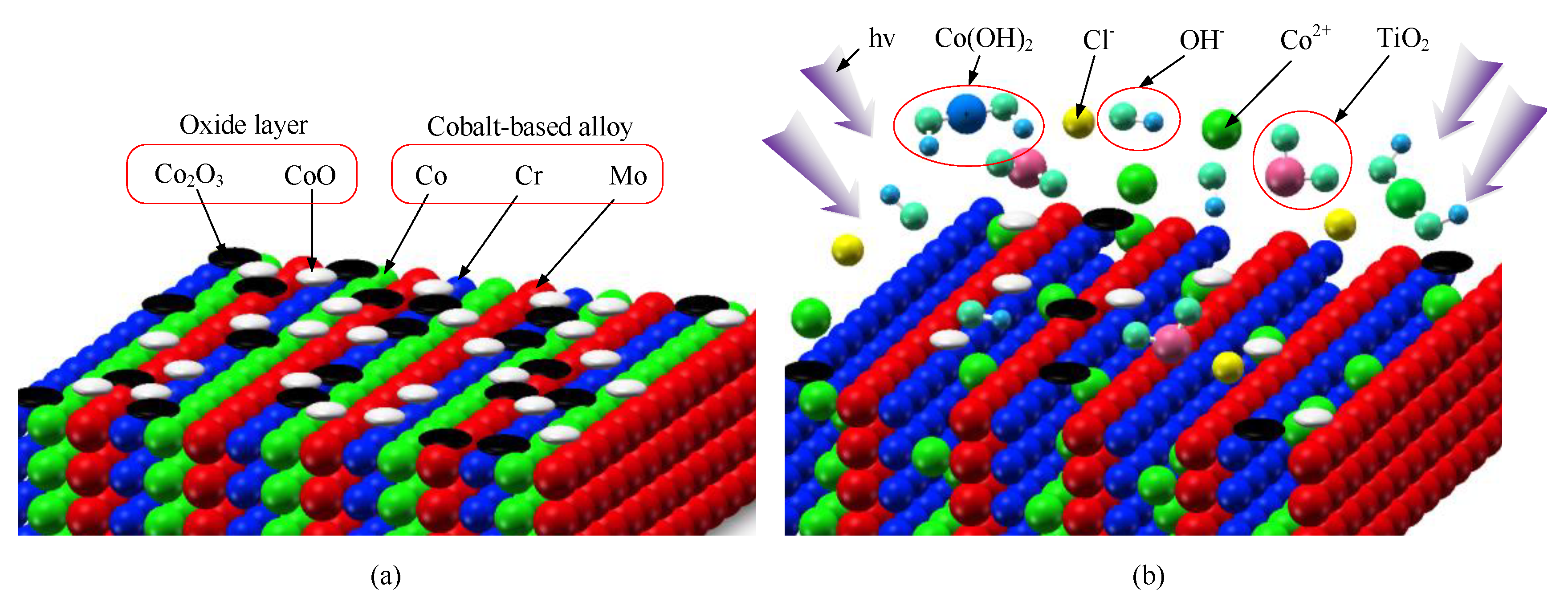
2.1. Photocatalytic Material Removal Principle

Cobalt-based alloy is a type of high-hardness alloy composed of Co, Cr and Mo. It is difficult to remove quickly by conventional machining methods. Obviously, if difficult-to-process materials can be changed into easy-to-process materials by specific methods, the processing efficiency may be greatly improved. During high-temperature processing, a divalent oxide CoO is formed on the surface of cobalt-based alloys, and Co may be further oxidized to Co2O3 when in the presence of air for a long time [34,35]. Therefore, both Co and Co2O3 oxide layers should be considered during processing pretreatment of cobalt-based alloys.
According to previous studies, Co and its Co2O3 oxide layer can be converted into soluble cobalt salt using a corrosive solution [34]. Thence, in this study, mechanical pretreatment of cobalt-based alloys was carried out using TiO2 + Basic Yellow 40 solution under ultraviolet (UV) ray photocatalytic conditions. The chemical formula of Basic Yellow 40 is C22H24ClN3O2, and its English alias is “1h-benzimidazolium, 2-(7-(diethylamino)-2-oxo-2h-1-benzopyran-3-yl)-1, 3-dimethyl-chloride”. It is a substance similar to cathilon dye. Our specific implementation method involved immersing the cobalt-based alloy sample in the corrosion solution, and externally irradiating it with UV light for a suitable time. This method was only to show the effect of ultraviolet light, as irradiation with ultraviolet light can enhance the ionization of cobalt-based alloys. Through a chemical corrosion solution configuration test, we concluded that cobalt in the solution was irradiated when the ultraviolet light was turned on, and the content of Co2+ increased significantly. In addition, the processing properties of the cobalt-based alloys were improved. This was only a function of the sparse metal oxide layer on the surface of the cobalt-based alloy, and did not affect the corrosion resistance or high hardness of the alloy itself. Figure 1 shows the surface model comparison of cobalt-based alloys before and after photochemical pretreatment.
As can be seen in Figure 1, hv stands for the photon energy under ultraviolet light catalysis. The etching solution used was a Basic Yellow 40 solution to which TiO2 had been added. The specific implementation method involved the cobalt-based alloy sample being immersed in the etching liquid, with external irradiation performed under ultraviolet light for a suitable time. The main reaction process was as follows:
After TiO2 is irradiated with UV light, electrons are excited by the valence band to the conduction band, producing a highly active electron ( e ) on the conduction band and leaving a hole ( h + ) in the valence band [36]. The reaction equation is shown in Equation (1) [37]:
TiO 2 + hv e + h +
Under the action of the hole h + , H2O is oxidized to form a highly reactive hydroxide radical OH and H + . The reaction equation is shown in Equation (2) [38]:
H 2 O + h + OH + H +
The generated electron e reacts with dissolved oxygen O 2 in water to produce an oxygen radical ion O 2 . The reaction equation is shown in Equation (3):
e + O 2 O 2
OH is produced by the oxygen radical ion O 2 . The relevant reaction equations are shown in Equation (4) through Equation (7) [39]:
O 2 + H + HO 2
2 HO 2 O 2 + H 2 O 2
O 2 + e + 2 H + H 2 O 2
H 2 O 2 + e OH + OH
Co2O3 is an amphoteric oxide, soluble in acid and alkali, so an alkaline environment provided by Basic Yellow 40 solution will gradually dissolve a Co2O3 oxide layer and convert it into soluble cobalt salt. As this oxide layer dissolves, Co can be oxidized to Co2+ under UV light irradiation. Part of Co2+ and the OH provided in Equation (7) are combined into water-insoluble Co(OH)2. The reaction equation is shown in Equation (8):
Co + + 2 OH Co ( OH ) 2
Another fraction of Co2+ reacts with Cl (produced by Basic Yellow 40), producing CoCl2. The reaction equation is shown in Equation (9):
Co 2 + + 2 Cl CoCl 2
CoCl2 is a water-soluble salt, and Co(OH)2 is a water-insoluble base. Thus, under the action of Basic Yellow 40 + TiO2 corrosion solution and UV photocatalysis, elemental cobalt on the surface of a cobalt-based alloy will eventually be converted into soluble CoCl2 and insoluble Co(OH)2 precipitate, leading to an alloy with a loose microstructure surface which is easy to remove by machining.

2.2. Photocatalytic Cobalt-Based Alloy Material Removal Test

Chemical Corrosion Solution Configuration Test

Figure 2 displays the devices used for establishing a corrosion solution configuration test.
The material used in the corrosion solution configuration test was Stellite 6B cobalt-based alloy coating on steel No. 45. The wavelength of the UV light was set to 356 nm. Three types of corrosive liquid were prepared, and the amount of each component in the liquids is shown in Table 1.
According to research in the field of chemistry, TiO2 film doped with Co2+ has obvious absorption of UV light of wavelengths 250 nm to 380 nm [40]. Therefore, a high-pressure mercury lamp with UV light (P: 100 W) was selected to increase the photocatalytic effect. In order to ensure the same ultraviolet light intensity for each group, the angle of the ultraviolet light was kept constant, and the distance between the fixed ultraviolet lamp and the solution remained unchanged.
Cobalt-based alloy samples were immersed in the three corrosive solution types. Tests were subsequently carried out under both non-photocatalytic and photocatalytic conditions. Since the cobalt-based alloy forms an oxide layer on the surface during high-temperature processing, the test time could not be too short. Thus, 3 h was selected. The solubility of cobalt was analyzed by XPS (X-ray photoelectron spectroscopy), and the surface corrosion effect of each test group was observed using the KEYENCE VW-6000 dynamic analysis three-dimensional display system (Osaka, Japan).

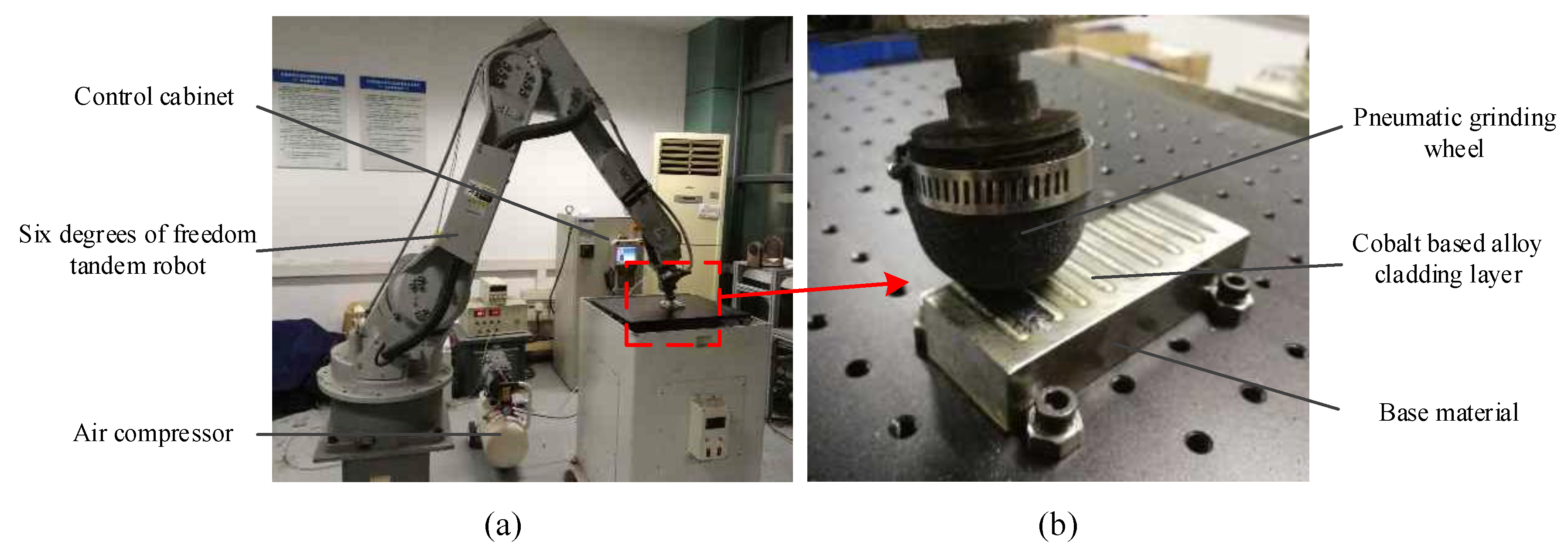
2.3. Pneumatic Wheel Processing Test

In this part, combined with the pretreatment method determined in Section 3.1, the rationality of the removal method of cobalt-based alloy material under photocatalytic conditions was further verified by a mechanical processing test.
Firstly, a small cobalt-based alloy processing test platform, based on the six-degree-of-freedom industrial robot MOTOMAN-HP20 (Kitakyushu, Japan), was established. An air-pressing machine and a pneumatic wheel were used for the polishing test. Figure 3 displays the test platform used for cobalt-based alloy processing.
Using the platform shown in Figure 3, material removal processing tests were performed on the cobalt-based alloys under three different processing conditions. The three condition types were: Pure mechanical processing conditions (Tra), chemical pretreatment + mechanical processing conditions (Tra + Che), and UV photocatalysis + chemical pretreatment + mechanical processing conditions (Tra + Che + UV). Table 2 lists the uniform process parameters under the three processing conditions.
The test parameters were set according to the results of previous research groups on the removal of pneumatic wheel materials [41,42,43]. According to the test surface size of the cobalt-based alloy sample and the requirements of industrial processing efficiency, the processing time was set to 10 min to verify the efficiency of the new method.
A GH-202 electronic analytical balance from A&D Company (Tokyo, Japan), was used to measure the mass change of the cobalt-based alloy before and after processing. Additionally, an NT9800 white light interferometer from Veeco (LongIsland, NY, USA), was used to measure the surface roughness, Ra, and topography of the cobalt-based alloy before and after processing.

3. Results and Discussion

3.1. Chemical Corrosion Solution Configuration Test

Table 3 provides the test results of the solubility analysis of cobalt by XPS.
As seen in Table 3, elemental cobalt was insoluble in the catalytic solvent under the function of TiO2 and water, even with UV photocatalysis. In contrast, part of the cobalt element was converted into Co2+ under the action of Basic Yellow 40 and water, as Co2+ reacted with Cl ions provided by Basic Yellow 40 to form CoCl2. As a result, Co showed slightly soluble characteristics under such conditions. After applying UV photocatalysis, the amount of dissolution increased slightly, but it was still in the marginally soluble stage. In the test group of TiO2 + Basic Yellow 40 + water, the solubility of the cobalt element was noticeably increased. Additionally, after UV light catalysis was applied, the solubility of the elemental cobalt was further improved.
As discussed previously, the corrosion solution of TiO2 + Basic Yellow 40 + water, combined with UV photocatalysis, can make cobalt and its oxide layer on the surface of cobalt-based alloys form soluble substances, resulting in a remarkable surface corrosion effect.
Figure 4 shows the surface topographies of the cobalt-based alloys before and after corrosion, as observed by the dynamic analysis of a three-dimensional display system.
As illustrated by Figure 4a,b, elemental cobalt in the surface layer of the cobalt-based alloy was converted into soluble CoCl2 and insoluble Co(OH)2 after immersion in the TiO2 + Basic Yellow 40 solution. Significant corrosion marks appeared on the surface of the sample after cleaning. Compared with the corresponding surface profile figures, it was also found that the surface material was slightly removed, indicating that the surface structure was damaged to some extent. After increasing the UV photocatalytic effect, the corrosion marks were obvious and the surface structure was further destroyed. The surface profile peaks were significantly reduced and the surface structure was obviously destroyed (Figure 4c). Compared with the original surface topography (Figure 4a), the corroded surface of the metal became looser than the previously untreated surface, and the surface metal structure was greatly damaged. At the same time, a large number of pits could be found after corrosion by observing the corrosion morphology (Figure 4b,c). The reason for this was that the cobalt-based alloy was essentially a cobalt-chromium-molybdenum alloy—i.e., the surface was not composed of a single element, as it also contained other elements like chromium and molybdenum. The corrosion solution proposed in this paper was only suitable for elemental cobalt and its compounds in the cobalt-based alloy, rather than other elements on the surface of the alloy. Thus, the corrosion solution caused the surface unevenness observed in Figure 4. In summary, the corrosion process was non-uniform and did not cause significant material removal of the alloy surface, resulting in a desired surface quality. Only with subsequent machining could the ideal machining effect be achieved.
Combined with the results of the XPS analysis in Table 3, it could be determined that a large amount of elemental Co was dissolved under the applied chemical corrosion pretreatment on the surface of the cobalt-based alloys. After adding ultraviolet light irradiation conditions, the corrosion solution had a stronger destructive force to the alloy structure in the same time frame. Consequently, through a pretreatment of UV photocatalysis + chemical etching, we were able to obtain a loose cobalt-based alloy surface structure, which was convenient for subsequent material processing.

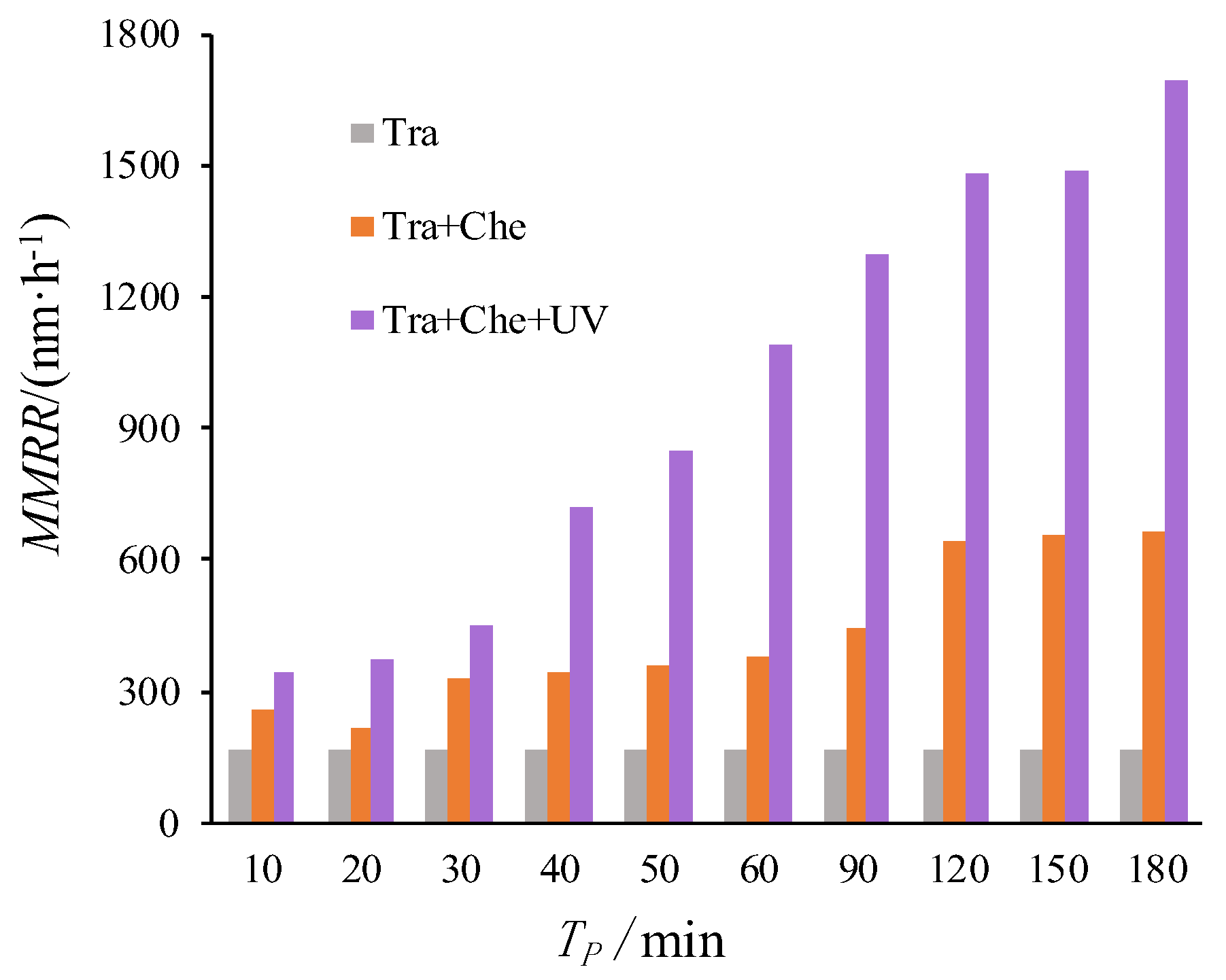
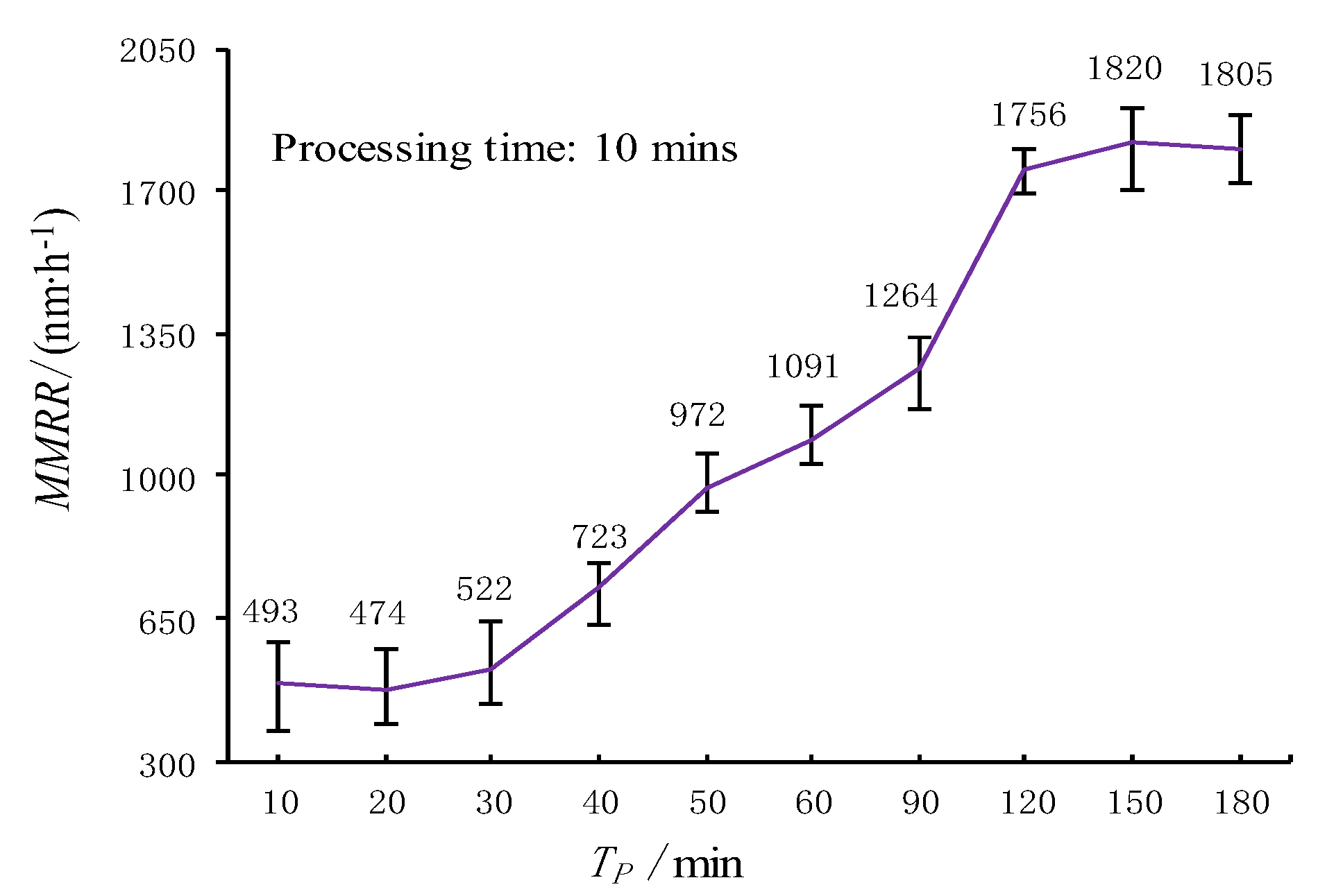
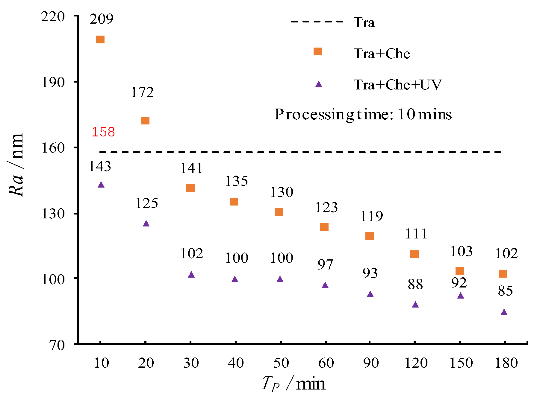
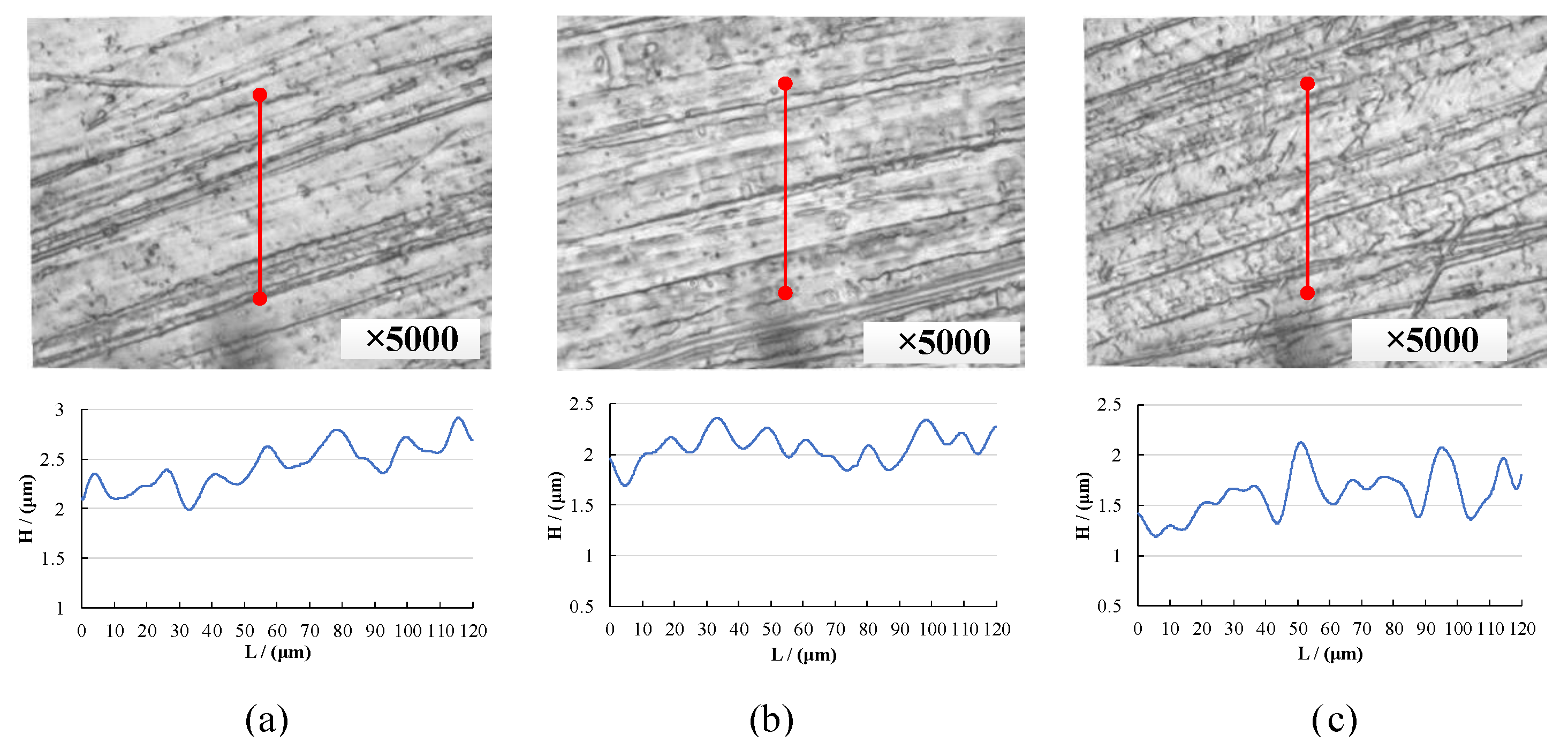
3.2. Pneumatic Wheel Processing Test

Mechanical material removal rates (MMRRs) were determined by measuring the mass changes of the workpieces before and after polishing [44,45,46]. Equation (10) is the formula used to calculate the mechanical material removal rate:
M M R R = Δ m ρ S T p
where Δ m is the quality difference before and after polishing, ρ is the density of the cobalt-based alloy, S is the area of polishing, and T p is the processing time.
Figure 5 displays the MMRRs under the three different testing conditions outlined in Section 2.3. Note that single mechanical processing without no pretreatment conditions (Tra), which has a fixed MMRR, is provided in Figure 5 to facilitate a comparative analysis.
Part of the Co element on the surface of the cobalt-based alloy was oxidized and dissolved into CoCl2 or precipitated into Co(OH)2 following chemical pretreatment. The surface structure of the alloy was destroyed, and the MMRR was slightly increased. Under the same immersion time, the chemically pretreated alloy structure was sparser following UV photocatalysis, and the MMRR was further improved, which confirmed the high efficiency of the cobalt-based alloy removal method under photocatalytic conditions.
In order to explore the influence of pretreatment time on the cobalt-based alloy MMRR, a series of tests were carried out under the Tra + Che + UV condition. Figure 6 shows the results.
As seen in Figure 6, there was little change among the MMRRs for the ultraviolet photocatalytic + chemical corrosion pretreatment 10 min, 20 min, and 30 min in length. This was due to the presence of an amphoteric Co2O3 oxide layer in the cobalt-based alloy sample. The Co2O3 oxide layer limited the contact between Co and both the corrosion solution and ultraviolet light. Thus, it was difficult to dissolve a large amount of the Co element on the surface of the cobalt-based alloy to achieve surface corrosion. Consequently, the surface change was not large and the processing efficiency was not improved. For the pretreatments 40–90 min in length, the Co2O3 oxide layer was gradually dissolved into the Basic Yellow 40 solution, and therefore more elemental Co was oxidized to Co2+ and dissolved in the corrosion solution or precipitated as Co(OH)2. The surface structure was damaged significantly after 90 min of pretreatment, and the MMRR nearly tripled compared to the shorter (10–30 min) pretreatment times. For the pretreatments 90–120 min in length, the Co2O3 oxide layer was further dissolved, a large amount of Co elements was dissolved into the solution, the surface was extensively destroyed, and the MMRR was further improved by 28%. Although pretreatments of more than 120 min greatly reduced the difficulty of cobalt-based alloy processing, the MMRR was likely to cause excessive reaction and material removal on the surface of the material. Thus, selection of ideal pretreatment times should also consider the impact of machining quality.
In order to analyze the impact of the photocatalytic conditions on the resulting machining quality, the surface roughness, Ra, was firstly measured using an NT9800 white light interferometer. We selected a group of cobalt-based alloys with an Ra between 230 nm and 250 nm for these experiments. Figure 7 shows the change of Ra under the three different testing conditions mentioned above and outlined in Section 2.3.
As seen in Figure 7, the cobalt-based alloy was a kind of high wear-resistant and high hardness material, and the original surface structure seriously affected the removal efficiency of the material so that Ra was only reduced from 242 nm to 158 nm. After chemical corrosion pretreatment, with the help of dissolution of the Co and Co2O3 oxide layers, the Ra of the sample was reduced to 102 nm after pneumatic wheel processing. When the ultraviolet light catalysis condition was added in the pretreatment stage, the surface structure of the cobalt-based alloy material became sparser, and the machining difficulty was further reduced. As exhibited in Figure 7, after a pretreatment of 30–50 min, the pressure roller process could reduce the Ra to 100 nm, or even further to 85 nm.
Additionally, according to further analysis of the UV photocatalytic + chemical pretreatment + mechanical processing test group data in Figure 7, we also found that in the first 30 min of pretreatment, the machining difficulty was reduced and the surface quality was improved significantly. After processing by the pneumatic wheel, the Ra of the sample surface had been reduced to 100 nm. Following pretreatment of 30 min to 180 min, the improvement in machining quality by the pneumatic wheel was not significant, despite the surface metal being further dissolved and the processing difficulty being further reduced. Consequently, in the case of removal of cobalt-based alloy material by the pneumatic wheel, the processing difficulty of the modified surface was significantly reduced following 30 min of UV photocatalytic + chemical pretreatment.
Combined with the results of the MMRR analysis, it can be concluded that long-term material pretreatment can significantly improve the MMRR of cobalt-based alloy coatings, but the surface quality improvement effect is not obvious, and the material is easily removed in excess. Therefore, the time for UV photocatalytic + chemical pretreatment of cobalt-based alloy coatings should be set to about 30 min.
The surface topography of the samples was also observed using the NT9800 white-light interferometer. Figure 8 shows topographical views of the machined surfaces under the three different testing conditions.
As seen in Figure 8, only a small amount of material could be removed by the mechanical processing method without pretreatment, and the surface scratches were obvious after processing (Figure 8b). After chemical corrosion pretreatment, although the workpiece’s processing difficulty was reduced, the effect on scratch removal was not good (Figure 8c). Machining for 3 min could approach the surface quality of a single chemical corrosion pretreatment with machining. After 6 min of machining, the Ra was significantly reduced, and the surface scratches disappeared, indicating a significant improvement in surface quality. After machining for 10 min, the surface quality was basically level with the effects of 6 min of processing (Figure 8d). This suggests that cobalt-based alloy coating pretreated by UV photocatalytic + chemical corrosion should be processed for 6 min to obtain an ideal processed surface, and that the processing efficiency can be improved by more than 40% compared to the other two processing methods.
Due to the high temperature treatment of the cobalt-based alloy, a divalent oxide CoO was formed in the surface of the material. CoO was further oxidized to Co2O3 in air, so the surface treatment only affected the sparse metal layer on the surface of the cobalt-based alloy. As shown in Figure 4, we observed that, after the surface treatment, the microscopic morphology changed slightly, and the research on its processing characteristics was in line with its basic application. Due to the complex alloy composition, we will discuss the chemical composition of cobalt-based alloys in a future work.
In summary, the proposed method of removal of cobalt-based alloy material under photocatalytic conditions can not only significantly improve the MMRR and guarantee surface roughness, but can also reduce the occurrence of surface defects, such as surface scratches, protrusions, and dents. This provides support for the effectiveness of the removal method of cobalt-based alloy materials under photocatalytic conditions.

4. Conclusions

In this work, based on the current demand for precise machining of cobalt-based alloys in the industrial field, a chemical reaction principle and model of cobalt-based alloy under UV photocatalytic + chemical corrosion pretreatment is introduced, and a new method for removing cobalt-based alloy materials under photocatalytic conditions is proposed.
(1) By analyzing the solubility of the cobalt element using XPS technology, and with corroboration from a dynamic analysis of a three-dimensional display system, we found a pretreatment of UV photocatalysis + chemical etching can generate a kind of loose surface structure of a cobalt-based alloy—which is convenient for subsequent processing. Additionally, TiO2 + Basic Yellow 40 solution has been shown to be a viable corrosive solution.
(2) Through pneumatic wheel processing tests, we found the MMRR can be increased nearly three times after 30 min of UV photocatalytic + chemical pretreatment compared to traditional processing. Furthermore, it can help to avoid excessive material removal. After ultraviolet catalysis is added in the pretreatment stage, a pressure roller process can reduce Ra to 85 nm.
(3) After a cobalt-based alloy coating is mechanically processed on the basis of UV photocatalytic + chemical corrosion pretreatment for more than 30 min, the surface scratches, protrusions and depressions are easily removed, and the surface quality is remarkably improved. The mechanical processing efficiency of the proposed method can be improved by more than 40% compared with the traditional processing method.
The results of our tests and numerical analyses indicate that this new method may solve the problems of high hardness and high wear resistance of cobalt-based alloys, which is difficult to deal with using ordinary mechanical processing.

Author Contributions

Data curation, L.Q. and W.Q.; Formal analysis, F.X.; Funding acquisition, X.Z.; Investigation, Z.L.; Methodology, F.X.; Project administration, X.Z.; Supervision, S.J.; Validation, Q.Z.; Writing—original draft, X.Z. and F.X.; Writing—review and editing, Z.L. and M.S.

Funding

This work was supported by the National Natural Science Foundation of China, grant number 51875526; the Natural Science Foundation of Zhejiang Province, grant number LY18E050023. Project funded by China Postdoctoral Science Foundation and Fundamental Research Funds for the Provincial Universities of Zhejiang.

Conflicts of Interest

The authors declare no conflict of interest.

References

  1. Chen, C.R.; Lian, G.F.; Jiang, J.B.; Wang, Q.T. Simplification and experimental investigation of geometrical surface smoothness model for multi-track laser cladding processes. J. Manuf. Process. 2018, 36, 621–628. [Google Scholar] [CrossRef]
  2. Zhang, L.B.; Lv, H.P.; Tan, D.P.; Xu, F.; Chen, J.L.; Bao, G.J.; Cai, S.B. An adaptive quantum genetic algorithm for task sequence planning of complex assembly systems. Electron. Lett. 2018, 54, 870–871. [Google Scholar] [CrossRef]
  3. Li, C.; Ji, S.M.; Tan, D.P. Softness abrasive flow method oriented to tiny scale mold structural surface. Int. J. Adv. Manuf. Technol. 2012, 61, 975–987. [Google Scholar] [CrossRef]
  4. Tan, D.P.; Chen, S.T.; Bao, G.J.; Zhang, L.B. An embedded lightweight GUI component library and the ergonomics optimization method for industry process monitoring. Front. Inform. Technol. Electron. Eng. 2018, 19, 604–625. [Google Scholar] [CrossRef]
  5. Ge, J.Q.; Tan, D.P.; Ji, S.M. A gas-liquid-solid three-phase abrasive flow processing method based on bubble collapsing. Int. J. Adv. Manuf. Technol. 2018, 95, 1069–1085. [Google Scholar] [CrossRef]
  6. Tan, D.P.; Zhang, L.B. A WP-based nonlinear vibration sensing method for invisible liquid steel slag detection. Sens. Actuators B Chem. 2014, 202, 1257–1269. [Google Scholar] [CrossRef]
  7. Tan, D.P.; Ji, S.M.; Fu, Y.Z. An improved soft abrasive flow finishing method based on fluid collision theory. Int. J. Adv. Manuf. Technol. 2016, 85, 1261–1274. [Google Scholar] [CrossRef]
  8. Shi, S.H.; Xu, A.Q.; Fan, J.W.; Wei, H.P. Study of cobalt-free, Fe-based alloy powder used for sealing surfaces of nuclear valves by laser cladding. Nucl. Eng. Des. 2012, 245, 8–12. [Google Scholar] [CrossRef]
  9. Huebner, J.; Kata, D.; Kusiński, J.; Rutkowski, P.; Lis, J. Microstructure of laser cladded carbide reinforced Inconel 625 alloy for turbine blade application. Ceram. Int. 2017, 43, 8677–8684. [Google Scholar] [CrossRef]
  10. Shen, L.; Zhou, J.; Xiong, Y.B.; Zhang, J.S.; Meng, Y. Analysis of service condition of large hot forging die and refabrication of die by bimetal-layer weld surfacing technology with a cobalt-based superalloy and a ferrous alloy. J. Manuf. Process. 2018, 31, 731–743. [Google Scholar] [CrossRef]
  11. Tan, D.P.; Li, L.; Zhu, Y.L.; Zheng, S.; Ruan, H.J.; Jiang, X.Y. An embedded cloud database service method for distributed industry monitoring. IEEE Trans. Ind. Inform. 2018, 14, 2881–2893. [Google Scholar] [CrossRef]
  12. Li, L.; Qi, H.; Yin, Z.; Li, D.; Zhu, Z.; Tangwarodomnukun, V.; Tan, D. Investigation on the multiphase sink vortex Ekman pumping effects by CFD-DEM coupling method. Powder Technol. 2019, in press. [Google Scholar] [CrossRef]
  13. Xu, G.J.; Yang, W.Q.; Hang, Z.X.; Liu, X.Y.; Chi, H.L.; Ou, X.S. Performance of Clad Layer Using Mixed Powder of Stellite 6 and VC. J. Mech. Eng. 2017, 53, 165–170. [Google Scholar] [CrossRef]
  14. Zeng, X.; Li, J.H.; Ji, S.M.; Pan, Y.; Hang, W.; Chen, G.D. Research on machining characteristic of double-layer elastomer in pneumatic wheel method. Int. J. Adv. Manuf. Technol. 2017, 92, 1329–1338. [Google Scholar] [CrossRef]
  15. Hang, W.; Zhou, L.B.; Shimizu, J.; Yuan, J.L. A robust procedure of data analysis for micro/nano indentation. Precis. Eng.-J. Int. Soc. Precis. Eng. Nanotechnol. 2013, 37, 408–414. [Google Scholar] [CrossRef]
  16. Li, C.; Ji, S.M.; Tan, D.P. Multiple-loop Digital Control Method for a 400-Hz Inverter System Based on Phase Feedback. IEEE Trans. Power Electron. 2013, 28, 408–417. [Google Scholar] [CrossRef]
  17. Zeng, S.; Blunt, L. Experimental investigation and analytical modelling of the effects of process parameters on material removal rate for bonnet polishing of cobalt chrome alloy. Precis. Eng. J. Int. Soc. Precis. Eng. Nanotechnol. 2014, 38, 348–355. [Google Scholar] [CrossRef]
  18. Zeng, X.; Ji, S.M.; Jin, M.S.; Tan, D.P.; Li, J.H.; Zeng, W.T. Mechanical Characteristic Analysis of Softness Consolidation Abrasives Pneumatic Wheel. J. Mech. Eng. 2014, 50, 170–177. [Google Scholar] [CrossRef]
  19. Tan, D.P.; Li, P.Y.; Ji, Y.X.; Wen, D.H.; Li, C. SA-ANN-based slag carry-over detection method and the embedded WME platform. IEEE Trans. Ind. Electron. 2013, 60, 4702–4713. [Google Scholar] [CrossRef]
  20. Ji, S.M.; Ge, J.Q.; Tan, D.P. Wall contact effects of particle-wall collision process in two-phase particle fluid. J. Zhejiang Univ.-Sci. A 2017, 18, 958–973. [Google Scholar] [CrossRef]
  21. Lee, C.; Park, S. Damage visualization of pipeline structures using laser-induced ultrasonic waves. Struct. Health Monit. 2015, 14, 475–488. [Google Scholar] [CrossRef]
  22. Zhang, D.; Zhao, P.F.; Zhao, W.; Luo, Y.Y.; Xie, Y.H. Experimental Study of Laser Cladding Methods on Water Erosion Resistance to Low Pressure Blades Materials of Steam Turbine. Adv. Condens. Matter Phys. 2014, 2014, 318–327. [Google Scholar] [CrossRef]
  23. Tan, D.; Li, L.; Zhu, Y.; Zheng, S.; Yin, Z.; Li, D. Critical penetration condition and Ekman suction-extraction mechanism of sink vortex. J. Zhejiang Univ.-Sci. A 2019, 20, 61–72. [Google Scholar] [CrossRef]
  24. Chen, S.T.; Tan, D.P. A SA-ANN-based modeling method for human cognition mechanism and the PSACO cognition algorithm. Complexity 2018, 2018, 6264124. [Google Scholar] [CrossRef]
  25. Kato, T.; Higashijima, G.; Yazawa, T.; Otsubo, T.; Tanaka, K. Proposal of Disturb-ance-Compensating and Energy-Saving Control Method of Air Turbine Spindle and Evaluation of Its Energy Consumption. Precis. Eng.-J. Int. Soc. Precis. Eng. Nanotechnol. 2015, 43, 439–447. [Google Scholar] [CrossRef]
  26. Tan, D.P.; Zhang, L.B.; Ai, Q.L. An embedded self-adapting network service framework for networked manufacturing system. J. Intell. Manuf. 2019, 30, 539–556. [Google Scholar] [CrossRef]
  27. Zhang, L.; Wang, J.S.; Tan, D.P.; Yuan, Z.M. Gas compensation-based abrasive flow processing method for complex titanium alloy surfaces. Int. J. Adv. Manuf. Technol. 2017, 92, 3385–3397. [Google Scholar] [CrossRef]
  28. Tang, C.B.; Zhang, C.; Ma, A.M.; Liu, D.X.; Liu, C.S.; Yu, S.M. Effect of Cobalt-based Alloy Coating on Wear Resistance and Corrosion Resistance of Titanium Alloy. Rare Met. 2017, 41, 620–628. [Google Scholar] [CrossRef]
  29. Tong, W.H.; Zhao, Z.L.; Zhang, X.Y.; Wang, J.; Guo, X.M.; Duan, X.H.; Liu, Y. Microstructure and Properties of Laser Cladding Cobalt Based Alloy Coating on Ductile Iron Surface. J. Met. 2017, 53, 472–478. [Google Scholar]
  30. Xu, J.L.; Zhou, J.Z.; Tan, W.S.; Huang, S.; Meng, X.K.; He, W.Y. Thermal Corrosion Resistance of Electromagnetic Stirring Assisted Laser Cladding Cobalt-Based Alloy Coatings. J. Opt. 2019, 39, 355–363. [Google Scholar]
  31. Zhou, Y.; Pan, G.; Shi, X.; Gong, H.; Luo, G.; Gu, Z. Chemical mechanical planarization (CMP) of on-axis Si-face SiC wafer using catalyst nanoparticles in slurry. Surf. Coat. Technol. 2014, 251, 48–55. [Google Scholar] [CrossRef]
  32. Wang, J.; Wang, T.Q.; Pan, G.S.; Lu, X.C. Mechanism of GaN CMP Based on H2O2 Slurry combined with UV Light. ECS J. Solid State Sci. Technol. 2015, 4, 112–117. [Google Scholar] [CrossRef]
  33. Ye, Z.F.; Zhou, Y.; Xu, L.; Pan, G. UV LED Assisted 4H-SiC Chemical Mechanical Polishing. Nanotechnol. Precis. Eng. 2017, 15, 342–346. [Google Scholar] [CrossRef]
  34. Chizhova, N.V.; Mal’Tseva, O.V.; Zav’Yalov, A.V.; Mamardashvili, N.Zh. Copper(II), cobalt(II), cobalt(III), and tin(IV) 5,10,15,20-tetraphenyl tetrabenzoporphyrinates: Synthesis and properties. Russ. J. Inorg. Chem. 2017, 62, 683–687. [Google Scholar] [CrossRef]
  35. Sun, L.; Zhai, J.L.; Li, H.Y.; Zhao, Y.; Yang, H.J.; Yu, H.W. Study of Homologous Elements: Fe, Co, and Ni Dopant Effects on the Photoreactivity of TiO2 Nanosheets. ChemCatChem 2014, 6, 339–347. [Google Scholar] [CrossRef]
  36. Dan, Xu.; Yao, K.L.; Gao, G.Y.; Yang, L. Electronic and optical properties of N-doped, Co-doped as well as N,Co-codoped rutile TiO2. J. Magn. Magn. Mater. 2013, 335, 118–124. [Google Scholar] [CrossRef]
  37. Jiang, G.; Wang, X.; Wei, Z.; Li, X.; Xi, X.; Hu, R.; Tang, B.; Wang, R.; Wang, S.; Wang, T.; et al. Photocatalytic Hydrogen Production Performance of Cobalt-Doped Titanium Dioxide. J. Phys. Chem. 2011, 27, 2406–2410. [Google Scholar]
  38. Li, J.B.; Xiao, Q.S.; Li, L.C.; Shen, J.; Hu, D. Novel ternary composites: Preparation, performance and application of ZnFe2O4/TiO2/polyaniline. Appl. Surf. Sci. 2015, 331, 108–114. [Google Scholar] [CrossRef]
  39. Wang, W.S.; Wang, D.H.; Qu, W.G.; Lu, L.Q.; Xu, A.W. Large Ultrathin Anatase TiO2 Nanosheets with Exposed {001 Facets on Graphene for Enhanced Visible Light Photocatalytic Activity. J. Phys. Chem. C. 2012, 116, 19893–19901. [Google Scholar] [CrossRef]
  40. Li, S.T.; Zhou, G.W.; Wei, Y.Q. Study on preparation and photocatalytic properties of Co2+–TiO2. Appl. Chem. Ind. 2005, 34, 737–740. [Google Scholar] [CrossRef]
  41. Zeng, X.; Ji, S.M.; Jin, M.S.; Tan, D.P.; Ge, J.Q. Research on dynamic characteristic of softness con-solidation abrasives in machining process. Int. J. Adv. Manuf. Technol. 2016, 82, 1115–1125. [Google Scholar] [CrossRef]
  42. Zeng, X.; Ji, S.M.; Tan, D.P.; Jin, M.S.; Wen, D.H.; Zhang, L. Softness consolidation abrasives material removal characteristic oriented to laser hardening surface. Int. J. Adv. Manuf. Technol. 2013, 69, 2323–2332. [Google Scholar] [CrossRef]
  43. Zeng, X.; Ji, S.M.; Jin, M.S.; Tan, D.P.; Li, J.H.; Zeng, W.T. Investigation on Machining Characteristic of Pneumatic Wheel Based on Softness Consolidation Abrasives. Int. J. Precis. Eng. Manuf. 2014, 15, 2031–2039. [Google Scholar] [CrossRef]
  44. Tao, Y.J.; Gan, X.J.; Zhang, X.D.; Hu, L.F.; Peng, J.; Wang, J.; Feng, H. Effects of UV Irradiation on the Molecular Structure and Tensile Properties of Nucleated Polypropylene. Adv. Mater. Res. 2014, 905, 82–87. [Google Scholar] [CrossRef]
  45. Lee, H.S.; Jeong, H.D.; Dornfeld, D.A. Semi-empirical material removal rate distribution model for SiO2, chemical mechanical polishing (CMP) processes. Precis. Eng.-J. Int. Soc. Precis. Eng. Nanotechnol. 2013, 37, 483–490. [Google Scholar] [CrossRef]
  46. Wang, J.; Wang, T.Q.; Pan, G.S.; Lu, X.C. Effect of photocatalytic oxidation technology on GaN CMP. Appl. Surf. Sci. 2016, 361, 18–24. [Google Scholar] [CrossRef]
Figure 1. Surface model comparison of cobalt-based alloys before (a) and after (b) photochemical pretreatment.
Metals 09 00657 g001
Figure 2. Test devices of corrosion liquid configuration. (a). Non-photocatalytic test group, (b). Photocatalytic test group.
Metals 09 00657 g002
Figure 3. Test platform of cobalt-based alloy processing. (a). Overall structure, (b). Pneumatic grinding wheel structure.
Metals 09 00657 g003
Figure 4. Surface topographies and surface profile of cobalt-based alloys before and after corrosion. (a). Original surface, (b). Chemical corrosion, (c). UV light + Chemical corrosion.
Metals 09 00657 g004
Figure 5. Mechanical material removal rate (MMRR) changes under different processing conditions.
Metals 09 00657 g005
Figure 6. Effect of pretreatment time on MMRR of new processing method.
Metals 09 00657 g006
Figure 7. Surface roughness changes under different conditions.
Metals 09 00657 g007
Figure 8. Surface topographies under three different processing conditions. (a). The original workpiece, (b). Mechanical processing conditions (Tra), (c). Chemical pretreatment + mechanical processing conditions (Che + Tra), (d). UV photocatalysis + chemical pretreatment + mechanical processing conditions.
Metals 09 00657 g008
Table 1. Composition and ratio of corrosion liquid.
GroupH2OTiO2Basic Yellow 40
(g)(g)(g)
A24550
B24505
C24555
Table 2. Process parameter settings under three processing conditions.
Balloon DiameterAirbag Elastic ModulusWheel Abrasive MaterialAbrasive DiameterAir Pressure
(mm)(MPa)-(μm)(MPa)
5011.9Al2O3750.2
Pressing AmountWheel InclinationWheel SpeedProcessing Time
(mm)(Rad)(r·min−1)(min)
0.50.50.410
Table 3. Cobalt solubility analysis results.
SchemeCorrosion LiquidUVTime of ReactionContent of Co2+
/h/mg·L−1
1AOff30.39
2AOn30.05
3BOff312
4BOn315
5COff323
6COn364

