Review

Advanced Metal Matrix Nanocomposites

1
Department of Mechanical Engineering, Isfahan University of Technology, Isfahan 84156-83111, Iran
2
Department of Mechanical Engineering, San Diego State University, San Diego, CA 92182, USA
3
Department of Mechanical Engineering, University of Nevada Reno, Reno, NV 89501, USA
4
Magnesium Innovation Centre, Helmholtz Zentrum Geesthacht, 21502 Geesthacht, Germany
5
Regional Centre of Advanced Technologies and Materials, Departments of Physical Chemistry and Experimental Physics, Palacky University, Šlechtitelů 27, 783 71 Olomouc, Czech Republic
6
Department of Mechanical Engineering, National University of Singapore, 9 Engineering Drive 1, Singapore 117576, Singapore
*
Authors to whom correspondence should be addressed.
Metals 2019, 9(3), 330; https://doi.org/10.3390/met9030330
Submission received: 24 January 2019 / Revised: 2 March 2019 / Accepted: 9 March 2019 / Published: 15 March 2019

Abstract

:
Lightweight high-strength metal matrix nano-composites (MMNCs) can be used in a wide variety of applications, e.g., aerospace, automotive, and biomedical engineering, owing to their sustainability, increased specific strength/stiffness, enhanced elevated temperature strength, improved wear, or corrosion resistance. A metallic matrix, commonly comprising of light aluminum or magnesium alloys, can be significantly strengthened even by very low weight fractions (~1 wt%) of well-dispersed nanoparticles. This review discusses the recent advancements in the fabrication of metal matrix nanocomposites starting with manufacturing routes and different nanoparticles, intricacies of the underlying physics, and the mechanisms of particle dispersion in a particle-metal composite system. Thereafter, the microstructural influences of the nanoparticles on the composite system are outlined and the theory of the strengthening mechanisms is also explained. Finally, microstructural, mechanical, and tribological properties of the selected MMNCs are discussed as well.

Graphical Abstract

1. Introduction

Composites are a unique class of materials invariably favored by nature in its creation and humans from prehistoric times. Composites provide a unique capability of enhancing the selected properties of monolithic materials which remains superior to the monolithic counterparts [1,2]. The enhancement in the targeted property of a metallic matrix can be controlled through the selection of type, size, and the amount of reinforcement which forms the core of composite design. The research in metal-based composites gained pace primarily in 1970s when researchers attempted, stir casting, rheocasting, and powder metallurgy routes to unify metals/alloys with ceramic reinforcements [3,4] with captivating results. Improvements in mechanical properties, such as elastic modulus, creep, damping, and wear resistance, were typically reported [5,6]. Researchers used both continuous and micron-scale discontinuous reinforcements to enhance the properties of different metallic matrices until approximately the end of the 20th century. The development of continuously-reinforced metal matrix composites (MMCs) was limited for highly specialized sectors, such as the space segment, due to the high cost and complexity involved in the synthesis process. On the other hand, the synthesis of discontinuously-reinforced MMCs was successfully attempted using a range of processing techniques [1,7,8]. Around the year 2000, the interest in nano-materials was revived and the research gained stride in exploring the influence of nano-scale materials as reinforcement in metallic matrices [9,10]; Ni, Cu, Ti, Mg, and Al were particularly targeted. The use of nano-scale reinforcements led to hitherto unrealized promising results in improving a wide spectrum of properties pertaining to metallic matrices; often deployed reinforcements were primarily selected from oxide, carbide, boride, and nitride families. Moreover, carbon-based reinforcements, such as carbon nanotubes, buckyballs, graphene, and carbon nanoplatelets, were also critically investigated not only in metal matrix composites but also in polymer composites [11]. The following properties were enhanced due to the use of nano-scale reinforcements:
  • Tensile and compressive behavior.
  • Ductility or elongation to failure, a must for bend than break design philosophy.
  • High-temperature mechanical properties.
  • Creep.
  • Dynamic mechanical properties.
  • Wear resistance, including scratch resistance.
  • Coefficient of thermal expansion.
  • Damping.
  • Machining.
  • Ignition resistance.
  • Dry/wet corrosion resistance.
The property improvement in the case of MMCs ensues from a combination of factors, such as:
  • Judicious selection of matrix and reinforcement (including its length scale).
  • Careful selection of primary and secondary processing routes.
  • Heat treatment.
In the case of nano-MMCs, another important attribute that assists in property improvement is the minimization of particle-based damage mechanisms which are prevalent in micron-scale ceramic reinforcement particles. Particle damage mechanisms include:
  • Particle breakage under the application of stress triggering the initiation of cracks.
  • Matrix-reinforcement interfacial debonding under the application of stress.
Particle-based damage mechanisms lead to inferior mechanical properties of MMCs, especially the elongation to failure and fracture toughness, which is not desirable in engineering/biomedical applications. Accordingly, nano-MMCs enjoy a distinct advantage over micro-MMCs in many applications due to their superior combination of properties.
In addition to the choice of matrix and reinforcement, the improvement in properties of MMCs crucially depends on the processing route and the processing parameters that can provide a uniform distribution of reinforcement and a good matrix-reinforcement interface. In the case of mass production techniques, such as casting, the mixing of reinforcement in molten metal is challenging at the industrial scale without giving significant thermal exposure to reinforcement. The dispersion of ceramic reinforcement in molten metal is commonly attempted using:
  • Stirring to ensure a vortex [1,4]; or
  • The ultrasonic method [12,13,14].
In the stir-casting method, the parameters such as stirrer design, stirrer speed, and its location within the crucible are most important. Recently, ultrasonic cavitation-based dispersion of reinforcement has been attempted [14,15,16] which employs the transient (to the order of nano-seconds) micro hot spots that can reach localized temperatures of about 5000 °C and pressures above 1000 atm and heating/cooling rates above 1010 °C/s [16]. Such a strong impact coupled with high temperatures becomes catalytic in breaking up the nanoparticle clusters and cleans the particle surface culminating in promising results. In addition to these dispersion methods, researchers have also attempted to integrate ceramic powders with metallic matrices applying powder preforms through squeeze casting and melt infiltration methods. Gas injection of reinforcement particles in the crucible and gas injection of ceramic particles in disintegrated melt streams, such as in spray atomization and the deposition method, have also been reported [1,17]. Importantly, the existing conventional infrastructure that is used for metal processing and fabrication in the synthesis of metal matrix composites can be used with minor modifications for easy industrial adaptability.
MMCs endowed with superior combinations of properties arising due to the material design freedom are opening up new applications in multiple engineering and biomedical sectors [18]. For example, biocompatibility, specific strength, high bio-corrosion resistance, as well as cell growth capability are important for most biomedical applications, such as those composites used as orthopedic biomaterials [18,19,20]. Additionally, properties such as light-weight and high-strength are simultaneously demanded in some industrial applications, like those automotive structures where lightweight but high-strength metal matrix nanocomposites are employed [21].
This review attempts to provide a comprehensive strategy based on the multi-disciplinary knowledge base from researchers in this area which will hopefully be beneficial for students, researchers, and industrialists alike. The key topics discussed are:
  • Current state-of-the-art in the synthesis of nanocomposites.
  • An insight into microstructural characteristics of composites.
  • Dispersion mechanisms of nano-particles.
  • Mechanical responses, including tensile, compressive, torsion, fatigue, and damping properties.
  • Particular emphasis is placed on lightweight composites, such as those based on magnesium and aluminum due to their capability to mitigate greenhouse gas emissions and global warming due to a rapid expansion in the transportation sector [3].

2. Fabrication Methods

The main challenges in producing nano-particle reinforced composites (nanocomposites) are the formation of cluster (agglomeration of the particles) and non-uniform (inhomogeneous) distribution of the nano-particles within the metal matrix. Regardless of ultrasonic dispersion and its assistance in the fabrication of MMNCs, the main fabrication methods in processing and manufacturing methods are presented.

2.1. Stir-Casting

Stir-casting is a common, economical, and fairly simple method of producing metal matrix nanocomposites wherein the reinforcement particles are incorporated into the molten matrix metal (i.e., aluminum). A stirrer (impeller) is inserted into the molten metal and applies mechanical stirring with some rpm to get a uniform distribution of the particles with the molten metal. This process has been extensively used to incorporate ceramic, carbon nanotubes, graphene, and metal oxide particles to magnesium and aluminum matrices [22,23,24,25]. The main challenges of this technique are (i) the tendency of nanoparticles to cluster due to high surface area and resulting high van der Waals forces between them; (ii) poor wettability of the solid nanoparticles with the molten metal; and (iii) high density of porosity due to possible entrapment of the air induced by the rotating stirrer [26,27,28]. Figure 1 shows the schematic of the stir casting process. Hamedan and Shahmiri [23] studied the stir casting fabrication of A356—1 wt% SiC (aluminum powder with average grain size of 45 µm and SiC nanoparticles with the average size of 20–50 nm) nanocomposite wherein a specific stirring rate and temperature were identified to secure a great combination of mechanical properties; the ideal combination of stirring temperature and stirring rate were 750 °C and 700 rpm, respectively.
Ezzatpour et al. [30] assessed the microstructure and mechanical properties of Al6061-nanocomposite, reinforced with nano-Al2O3 particles (0.5, 1, and 1.5 wt%), produced by stir-casting. Upon casting, they extruded the nanocomposite materials at 550 °C and observed enhanced strength and ductility in the extruded samples compared with un-reinforced samples; increase in yield strength and tensile strength resulted with addition of nano-Al2O3 while reduction in ductility. Alam et al. [31] studied the mechanical properties and the microstructure of A356 aluminum alloys reinforced with 1 to 5% nano-SiC particle produced by the stir casting process with stirring at 550 ± 50 rpm, stirring duration of 10 min, and pouring of the molten slurry at 680 ± 20 °C increase of 41% in yield strength and 45% in ultimate tensile strength (UTS) was described.
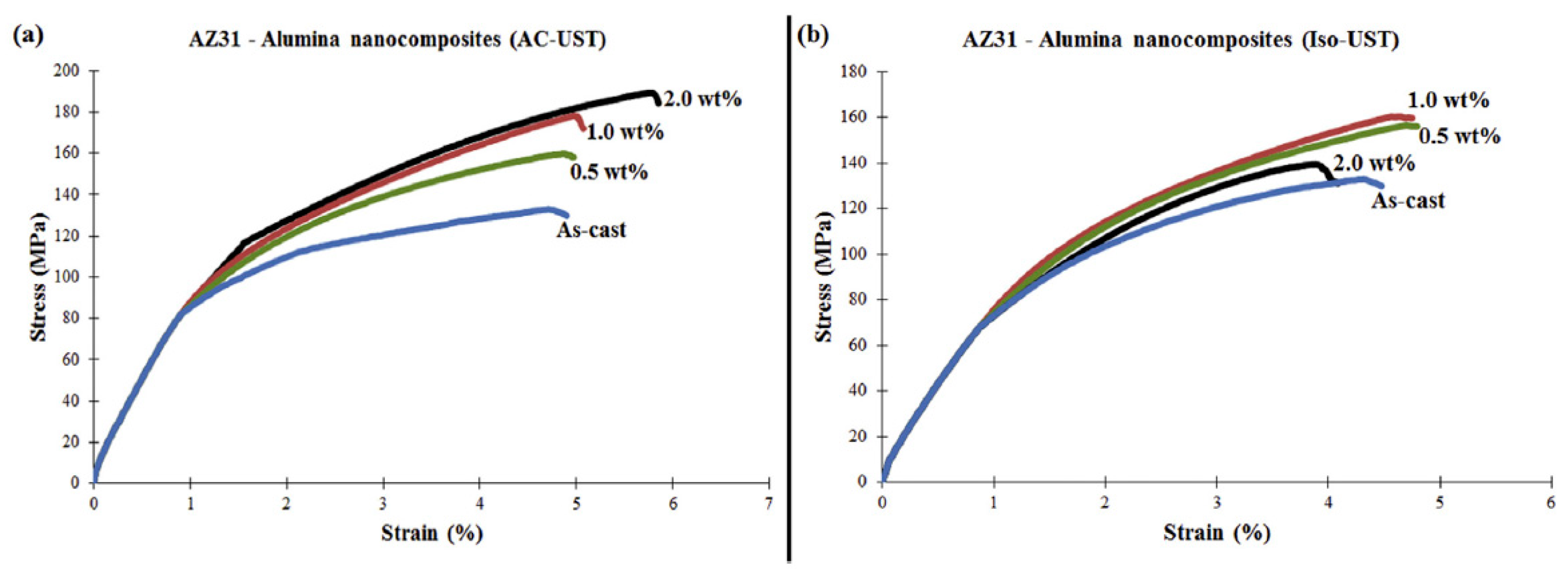
Khandelwal et al. [32] assessed the mechanical behavior of AZ31/Al2O3 magnesium alloy nanocomposites prepared using ultrasound-assisted stir casting (nano-sized alumina powder with the average size of 30 to 70 nm) with different wt% of alumina nanoparticles (0.5, 1.0, and 2.0 wt%). The melt was subjected to ultrasonic treatment (UST) under two different conditions, i.e., UST performed outside the furnace during air-cooling and nearly isothermal (Iso) UST within the furnace (see Figure 2). Grain refinement was attributed to the improved heterogeneous nucleation due to the addition of reinforcing particles. The reinforcing agent dispersed by UST greatly improved the mechanical response of the fabricated composite material (Figure 3). The coefficient of thermal expansion (CTE) as well as Orowan strengthening mechanism were the two factors contributing to the strength of the produced composites. The extensive fracture analyses revealed quasi-static cleavage fracture (brittle nature) in the iso-UST composite materials.

2.2. Disintegrated Melt Deposition (DMD)

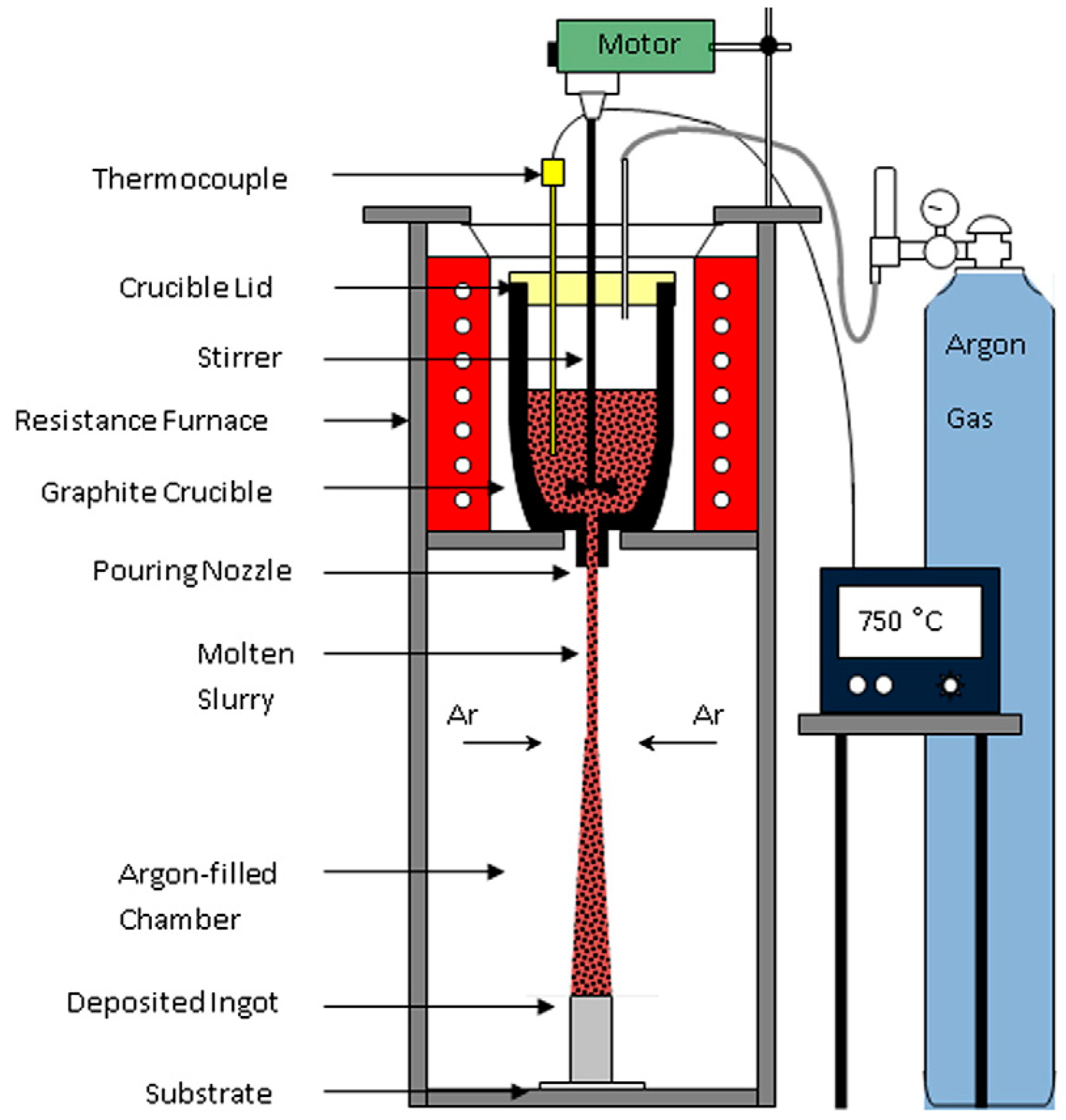
This stir casting-derived process has extensively been used for manufacturing of Mg-based nanocomposites [33,34,35,36,37] where a composite slurry, based on stir casting principles, is produced first. The ensuing slurry is then passed through a pouring nozzle with an inert gas jet (i.e., argon), at a superheated temperature (i.e., 750 °C); finally, the slurry is deposited on a metallic substrate. The end product of the DMD process is an ingot which then can be hot extruded to obtain the desired shape (Figure 4). This process is mainly used to produce Mg nanocomposites as it circumvents the major drawbacks of stir casting namely high density of oxides in the nanocomposite, and withholding of the reinforcement particles, i.e., Al2O3, SiC, Y2O3, B4C, BN, ZrO2, ZnO, CNT, in the crucible because of density differences between the particles and the Mg alloys [3]. For instance, Srivatsan et al. [38] produced an AZ31 + 1.5 vol% Al2O3 nanocomposite with the alumina particles (Al2O3) of 50 nm size. Upon the DMD process, the ingot was extruded with extrusion ratio 20.25:1 at 350 °C to achieve 8-mm diameter bars; the overall grain size of the reinforced nanocomposite was much finer than the monolithic AZ31 alloy due to pinning effect of evenly distributed alumina nanoparticles.

2.3. Semi-Solid Casting (SSC)

Semi-solid casting (SSC) is a high-integrity die casting technique, wherein metal is injected into a mold cavity in a semi-liquid/solid state with a “slushy” consistency with attributes of lower energy demands and less porosity, is more easily handled and requires less post-molding machining than metal cast using high-pressure die casting. However, it is difficult to generate the globular microstructure (globular solid particles suspended in the remaining liquid phase) needed for SCC. Zinc alloy AC43A nanocomposite with 0.5 wt% SiC β nanoparticle additions were cast at a 30% solid fraction [39]. AM60/SiC nanocomposite was obtained in a uniform microstructure form via semi-solid casting and a 19.3% and 7.9% increase in the elongation and the UTS, respectively, was discerned through the addition of 0.1 vol% of the nanoparticles [40].
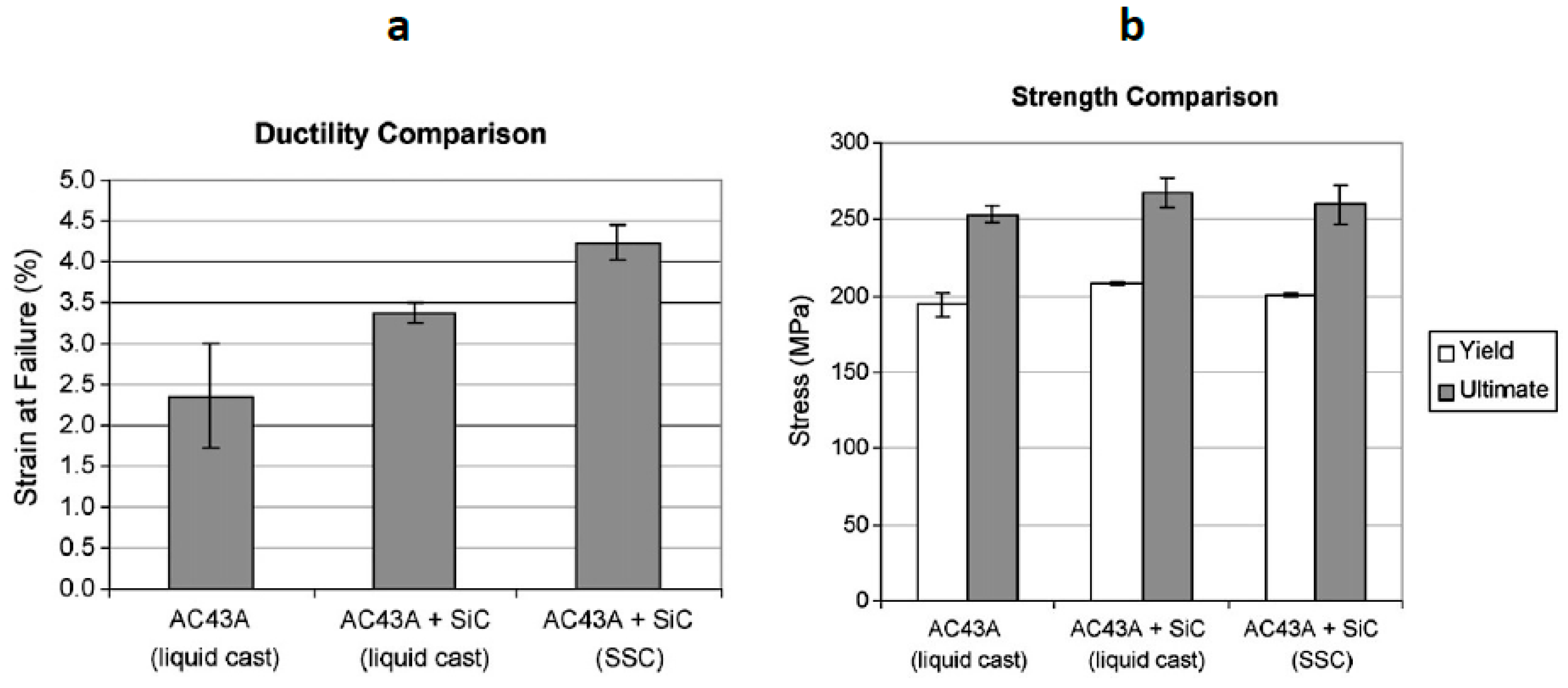
The combination of strength enhancement of the MMNC material with the beneficial processing of SSC was reported by DeCicco et al. [39,41] with reduced shrinkage, progressive mold filling and increased ductility for the semi-solid cast zinc alloy AC43A with 0.5 wt% SiC β (20–30 nm) nanoparticle addition compared to liquid cast monolithic AC43A zinc alloy and liquid cast AC43A/SiC nanocomposite, as shown in Figure 5.
The observed strength increase in the liquid cast AC43A/SiC systems is relatively small compared to other nanocomposite systems. There are no available mechanical testing results of semi-solid cast aluminum-based nanocomposites in the literature [39].

2.4. Powder Metallurgy (PM)

Powder metallurgy (PM), considered as a solid-state manufacturing method, is based upon three sequential steps: blending of the matrix metallic powders and the reinforcement particles in the desired composition, compaction to produce green compacts, and sintering using resistance or microwave (MW) energy. Upon sintering, another finishing process is applied to ensure consolidation of the produced composite which may involve equal channel angular pressing (ECAP) or an extrusion process at elevated temperatures. There are numerous advantages of PM over other manufacturing methods including:
  • Ability to produce “near-net” shape components;
  • Capability to integrate higher volume fractions of the reinforcement; and
  • Ability to produce large batches (i.e., for automotive applications).
Recently, Simões et al. [42] successfully produced aluminum and nickel matrix composites reinforced with carbon nanotubes (CNTs) using ultrasonication-assisted powder metallurgy as the dispersion/mixture process. They mixed different contents of CNTs (0.5 to 2.0 wt%) with the metallic powders in isopropanol; upon drying, the mixtures were uniaxially compacted and then sintered at elevated temperatures at different sintering times (i.e., 90 min at 640 °C for Al/CNT nanocomposites and 120 min at 950 °C for Ni/CNT nanocomposites). The PM technique, assisted with a novel “MW sintering” has been used extensively to produce different grades of Mg matrix nanocomposites [43,44,45,46]; MW heating is used to rapidly and effectively heat up the mixed powder particles as heat is generated within the powders, internally, and radiates outward (core-to-surface), which is contrary to what occurs in the conventional sintering process (surface-to-core) [44,45].
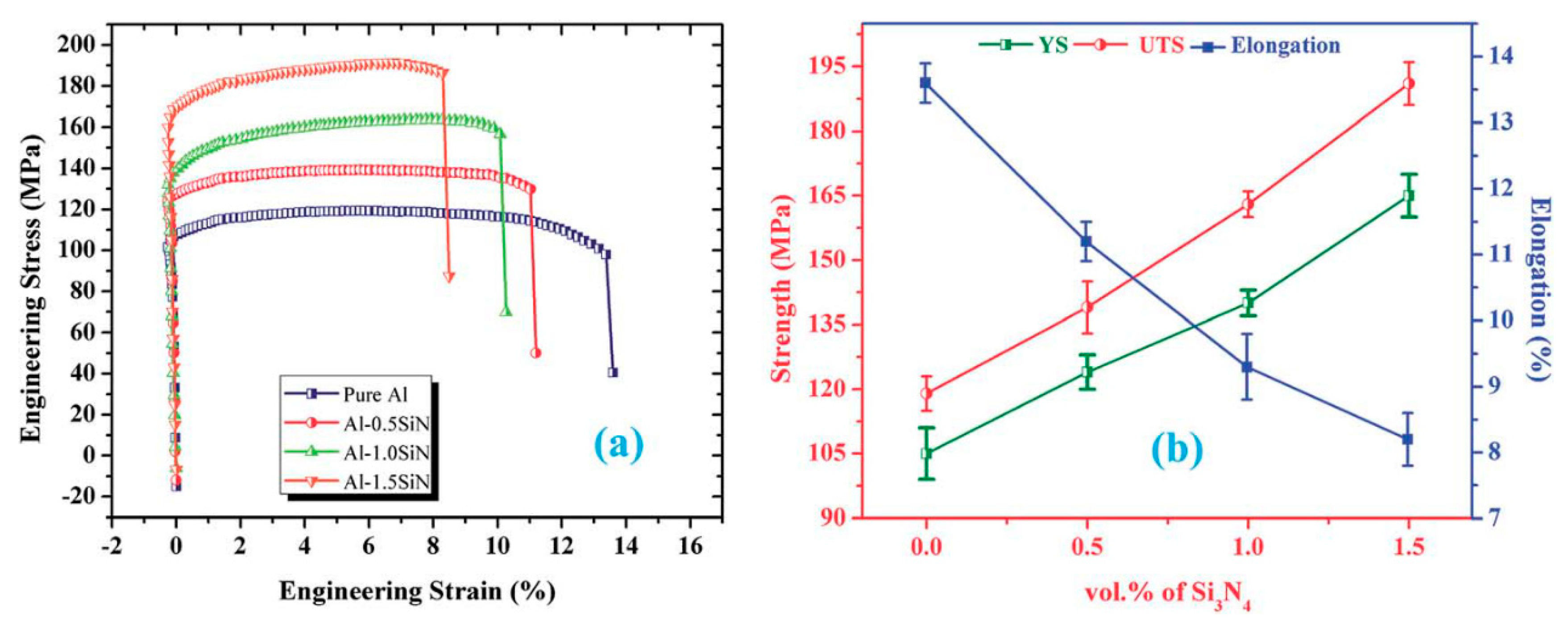
Recently, Matli et al. [47] used the PM process involving MW sintering followed by hot extrusion to produce Al–Si3N4 nanocomposites (silicon nitride with volume fraction of 0.5, 1.0, and 1.5%). They ball milled the mixture for 2 h at the milling speed of 200 rpm, then compacted the blended powders under 97 bar pressure and sintered the green product, using MW sintering, at 550 °C. Finally, an extrusion ratio of 20.25:1 was used to produce extruded rods of 8 mm diameter (Figure 6); the microstructure and mechanical properties of the produced nanocomposite were examined.
Their results indicate that the Si3N4 addition in the aluminum matrix leads to a linear increase in yield strength and UTS along with decrease in ductility (Figure 7).
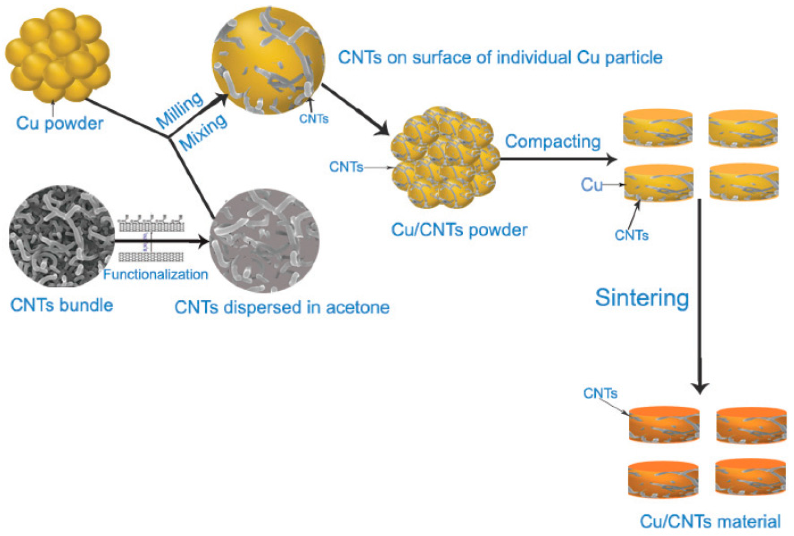
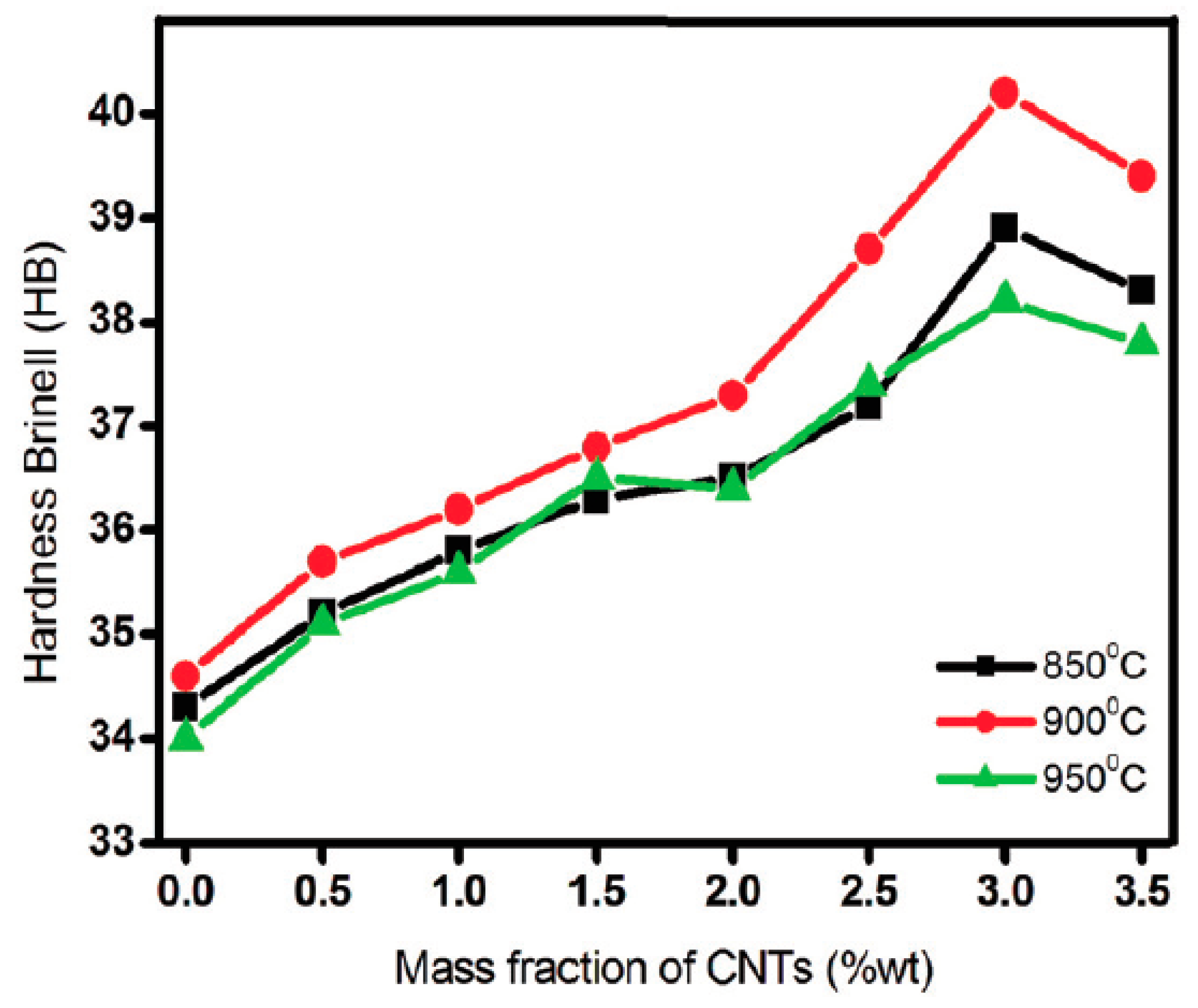
Pham et al. [48] utilized the PM technique to fabricate a Cu/CNT nanocomposite (CNT fraction from 0 to 3.5 wt%) and studied the effect of sintering parameters (850–950 °C for 2 h) on the mechanical properties and microstructure of the formed nanocomposite. The admixed copper powders (2–3 mm in size) with multi-walled carbon nanotubes (50 nm in diameter and 50 μm in length) were subjected to a high-energy ball milling (6 h at 300 rpm) which were then compressed and sintered at 850, 900, and 950 °C for 2 h in a pure argon atmosphere (Figure 8). An increase in the hardness trend with increase in the volume fraction of CNTs was observed up to 3 wt% which begins to drop, probably due to clustering/agglomeration when a larger volume fraction of the reinforcements (i.e., CNT) is added (Figure 9); based on Hall–Petch theory, and due to the grain grown at 950 °C sintering temperature, the hardness value of the sample processed at 950 °C was lower than the sample fabricated at 900 °C.
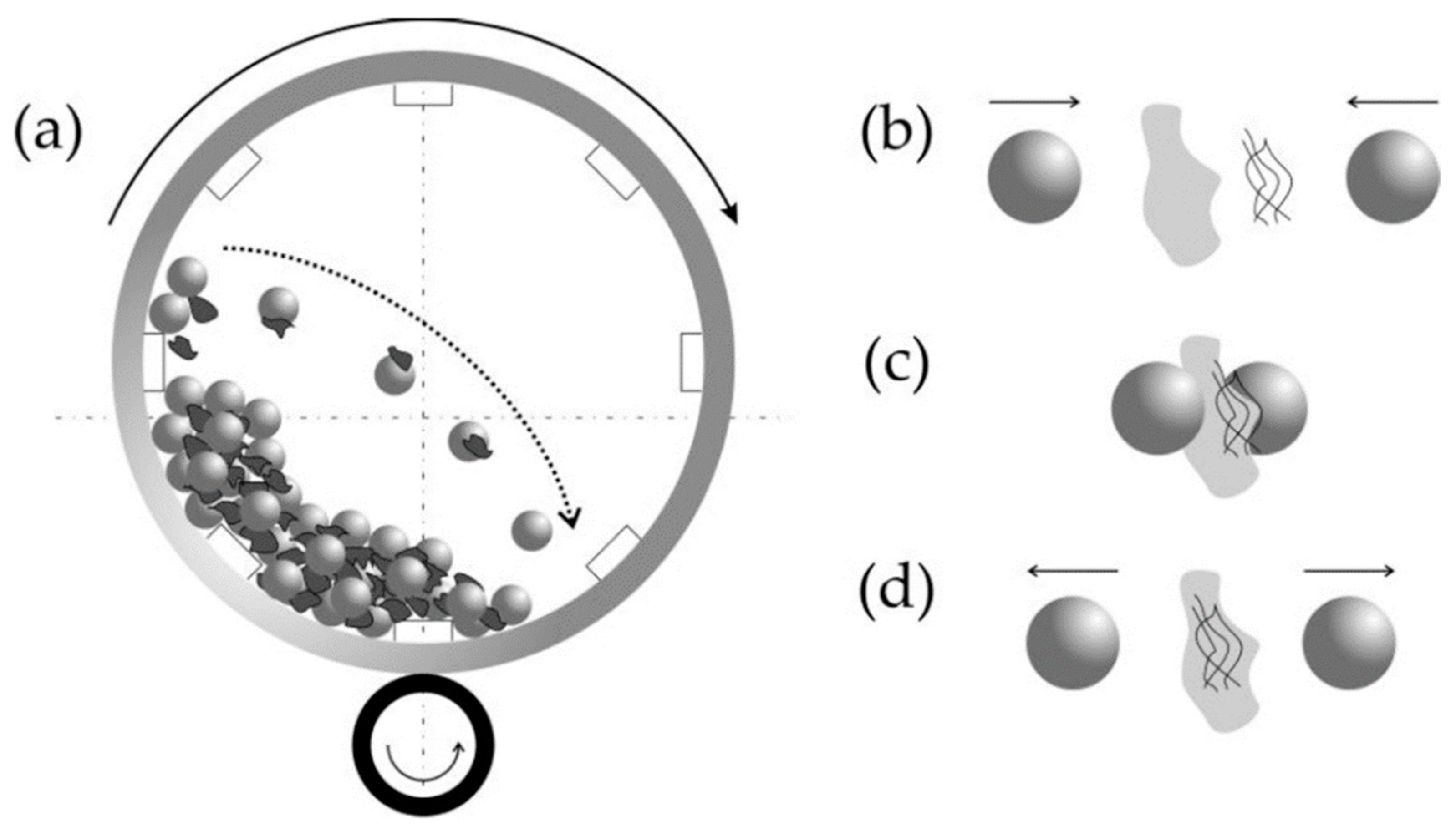
A sub-group of the PM technique for fabrication of MMNCs entails mechanical alloying upon which a high energy ball milling system is used to repeatedly cold weld, fracture, and re-weld the powder particles [49,50,51]. This practice is used greatly in metal matrix nanocomposites reinforced with ceramic particles since it can effectively break up the ceramic clusters and, therefore, enhances the uniform distribution of the ceramic particles in the metal matrix [52]. The main processing parameters in the mechanical alloying process comprise ball-to-powder ratio, time, and rotational speed of milling. Once the ball milling process is over, the rest of the process is similar to the PM which includes green compact and sintering; during the ball milling process, a process control agent (i.e., methanol, stearic acid, etc.) is sometimes added to prevent the formation of large powder clusters.
The ball milling process of a CNT-reinforced metal matrix bulk composite (i.e., Al/CNT nanocomposite) is shown in Figure 10 where the CNTs are integrated (partially welded) with the matrix powder metal (i.e., aluminum) at various steps; an effective ball milling process shall produce a well-dispersed (homogenized) distribution of reinforcement particles in the metal matrix.
To produce a fine dispersion of carbides, nitrides, and oxides in a light (non-ferrous) alloy matrix another term, reaction milling (i.e., reaction milling combines mixing and attrition with solid state reactions induced by mechanical agitation), has been used [3]; the processes control agent is not added to initiate the reaction. In this case, the milling atmosphere can be inert (or active) gases like argon, oxygen, nitrogen, or air [49].

2.5. Friction Stir Processing

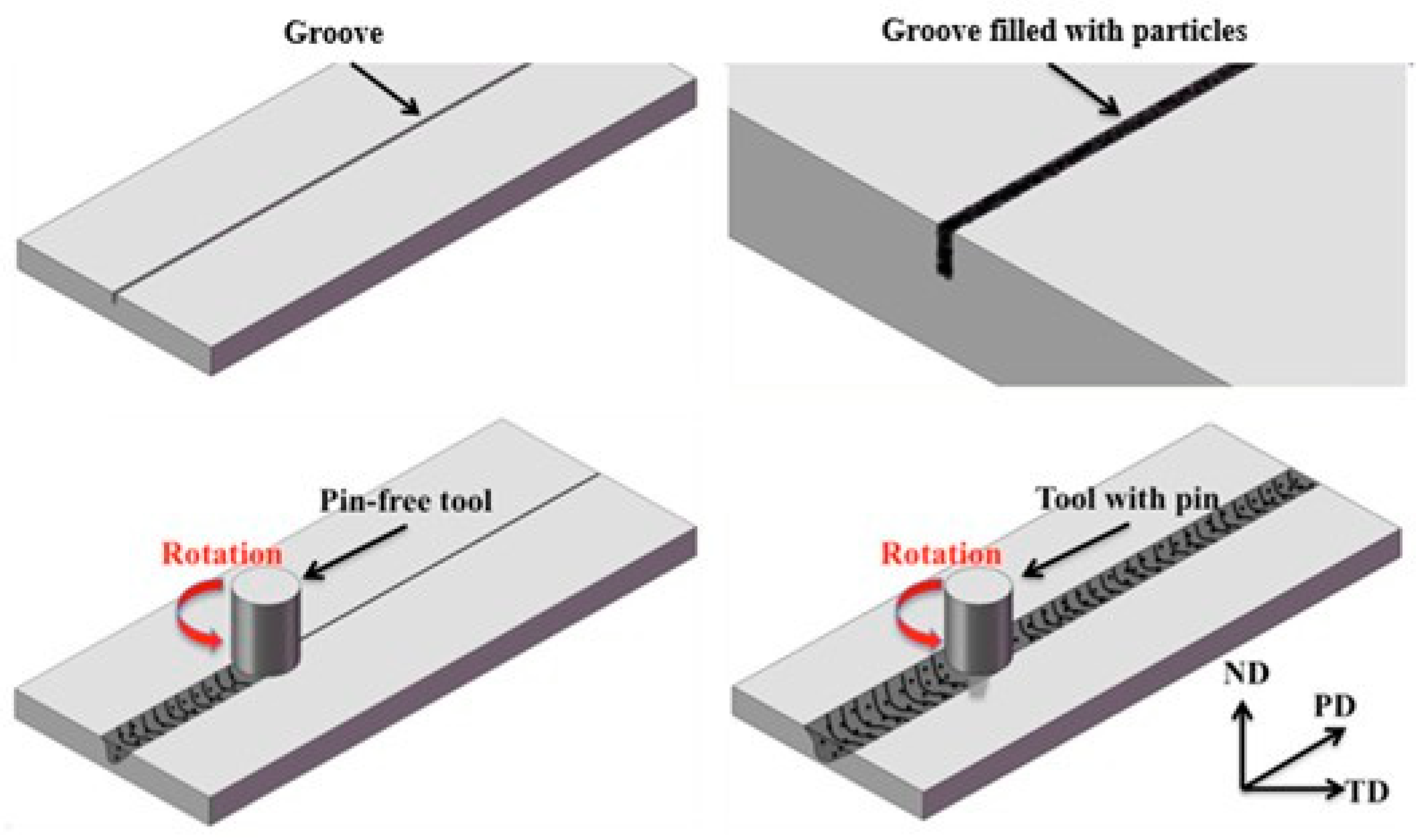
Friction stir processing (FSP), as a derivative of friction stir welding, is widely used by many researchers and industrialists [54,55,56,57,58,59,60,61,62,63,64] to incorporate nano-particles within a metallic matrix to produce bulk or surface nanocomposites. Initially, a groove is made with the base metallic material which is then filled with the desired volume fraction of the nanoparticles. Using a non-consumable rotating pin-less tool, which is plunged into the surface of the work piece, the groove is closed with the particles being encapsulated within the closed grove. In the next step, a tool with pin is used to disperse the particles, through a stirring process, with the bulk of the metallic substrate (Figure 11). The main challenge of this method is final surface finish of the processed product and uniform dispersion of the nano-sized particles within the matrix. This procedure still under development and has been used in fabrication of aluminum and magnesium based nanocomposites [63,64]; Arora et al. [65] have published a review paper on composite and nanocomposite fabrication using FSP.
Morisada et al. [54], for instance, filled multi-walled CNTs (diameter of 20–50 nm) into a groove (1 mm × 2 mm) on the AZ31 (rolled plates with thickness of 6 mm) and employed FSP to fabricate surface composites; good distribution of the nanotubes within the matrix at 1500 rpm and traverse speed of 25 mm/min was observed after exploring various parameters along with great grain refinement (less than 0.5 µm) in the FSPed specimens. Using the FSP principles, with a constant traverse speed of 45 mm/min and a rotational speed of 800 rpm, Lee et al. [55] fabricated an AZ61/SiO2 (average diameter of 20 nm) nanocomposite with volume fractions of 5 and 10%. Multi-pass FSP trials showed that the clustering phenomenon becomes inferior with increasing the number of the FSP passes in addition to significant grain refinement and improvement in the mechanical properties in the FSPed samples versus the starting materials.

2.6. Accumulative Roll Bonding

Originally introduced by Saito et al. [67] in 1998, accumulative roll bonding (ARB) is based upon severe plastic deformations imposed by rotating rolls on stacked metallic sheets and comprise the following steps (Figure 12):
  • wire brushing of metal sheet surfaces to remove the oxide layer, contaminants, etc.;
  • stacking of two sheets on top of each other;
  • roll bonding the sheets together up to a minimum 50% thickness reduction; and
  • dividing the roll-bonded sample into piece.s
A one-piece entity can be attained following these steps and the process can be repeated many times. The process has been used for fabricating different metal matrix nanocomposites, i.e., Al/SiC [68,69,70], Al/Al2O3 [71], Al/B4C [72], Al/CNT [73], Al/TiO2 [74], Al/SiO2 [75], Al/W [76,77], Al/WC [78], Al–Al2O3–Mg multilayer composite [79], and Mg/CNT [80].
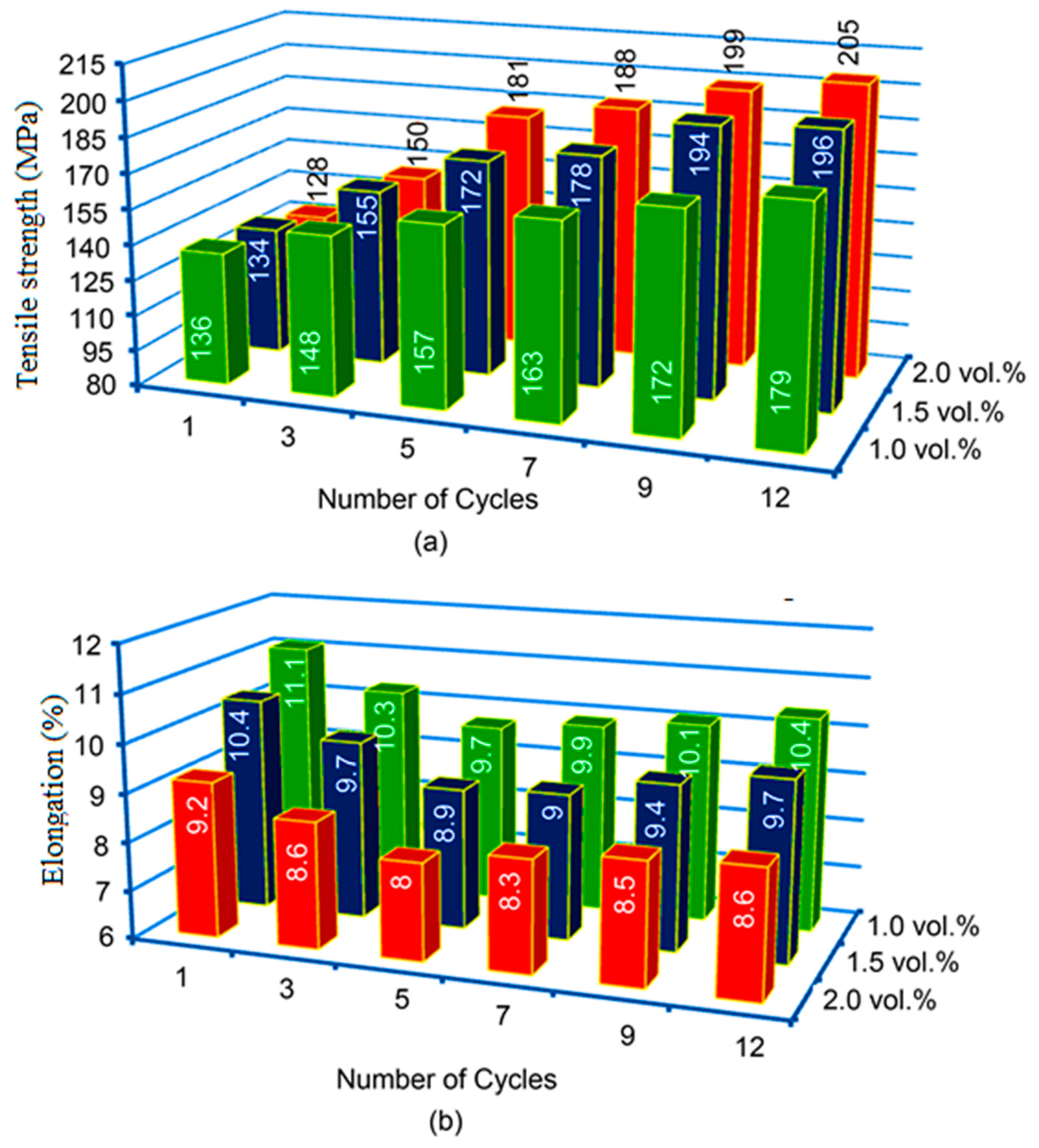
Al-based (AA1100) composite reinforced with nano- tungsten trioxide (WO3), with an average size of 80 nm and 1.0, 1.5, and 2.0 vol%, has been fabricated [81] for study of their microstructure and mechanical properties; good dispersion of nanoparticles within the matrix along with enhanced mechanical properties [81] was achieved upon 12 ARB cycles. Higher strength in the multi-pass ARBed samples is attributed to the grain refinement, strain hardening, and uniform distribution of the particles within the matrix (Figure 13).

3. Reinforcing Agents

The aim of reinforcement of metallic materials with nano-particles or fibers is always aimed to improve specific properties [82], typical development goals for composite materials being:
  • Increase in yield and tensile strength at room temperature or elevated temperature while maintaining ductility;
  • Increase of creep resistance at elevated temperatures;
  • Increased fatigue strength;
  • Improvement of thermal shock resistance;
  • Improvement of wear resistance;
  • Increase of the Young’s modulus; or
  • Reduction of coefficient of thermal expansion.
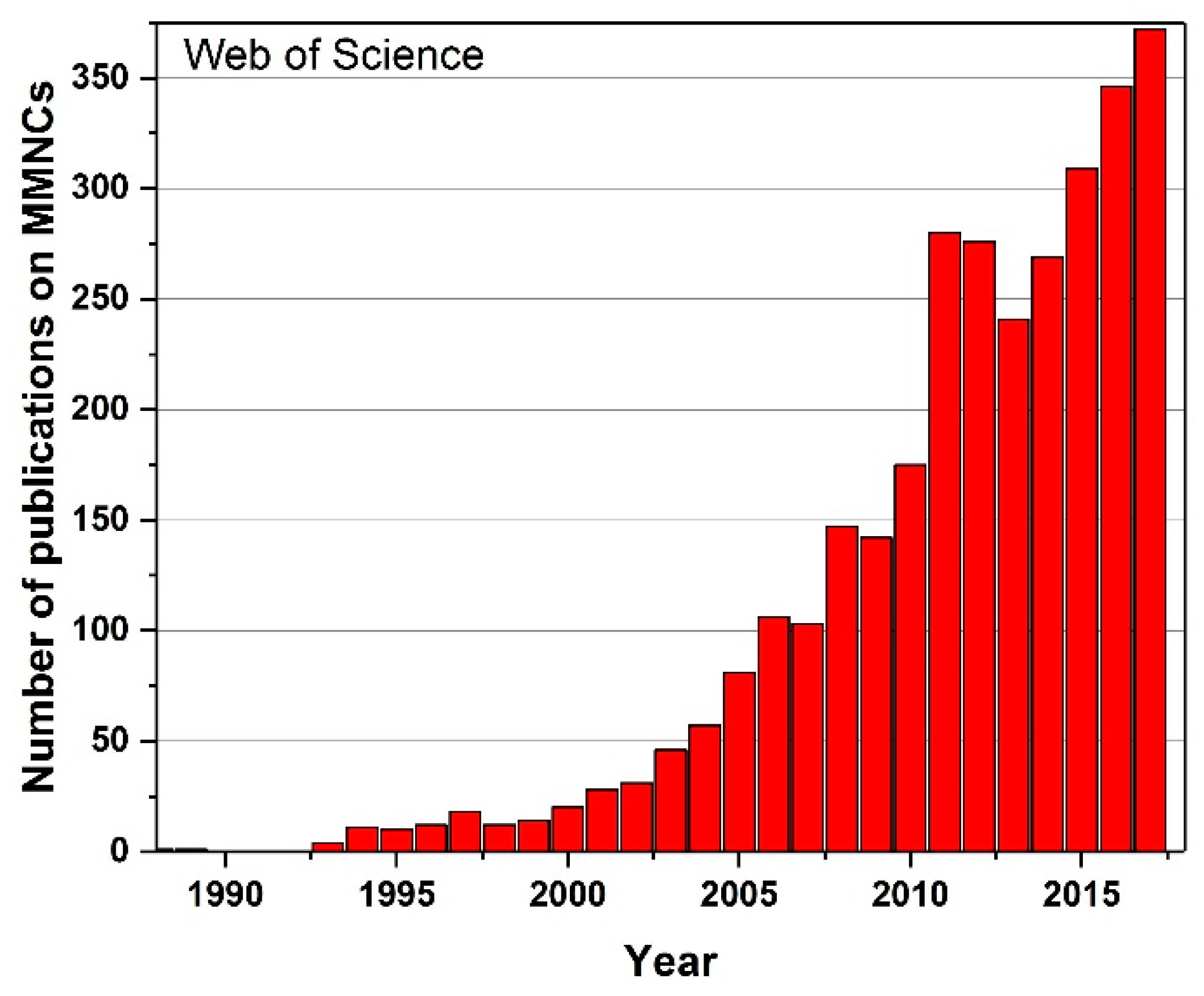
Ceramic nanoparticles and carbon-based nanotubes have been available in the last few years at significantly lower prices than in the 1980s or 1990s and has culminated in impressive promotion of the research and development of nanoparticle-reinforced light metals. Figure 14 shows the number of publications on metal matrix nanocomposites over the last 25 years.
The requirements for ceramic nanoparticles and their use in the metallic matrix to bring about the aforementioned improvements in properties, however, are rather customized by the combination of particles and matrix; low density is a requirement in order to curb the density of the composite. Furthermore, an obligatory mechanical compatibility exists, which is provided by a small difference in the coefficient of thermal expansion. Chemical compatibility is important at the outset to prevent the particles from dissolving in the melt but, at the same time, ensures good adhesion to the matrix. The melting point of the particles should be significantly higher than that of the matrix, which is typically the case with ceramic particles. A high modulus of elasticity and high strengths are vital and so is good wettability for metallurgical processing. Finally, the reinforcement component must also be inexpensive and, therefore, economical to procure.
Carbides, borides, nitrides, and oxides are used to reinforce metallic materials in the nanoparticle form [83,84], usually produced industrially at low cost and deployed in the grinding and polishing industry; especially, SiC, B4C, Al2O3, AlN, BN, and TiB2 are technically and economically relevant examples. Table 1 shows some relevant properties of the ceramics listed above and Table 2 lists common ceramic nanoparticles useable for metal matrix nanocomposite production.
The size and shape of nanoparticles varies greatly. The particle sizes of a few nanometers in diameter are available while their shape varies between round, block-shaped, rectangular, flat, and filamentary.
Both carbon nanotubes (CNTs) and nanodiamonds (NDs) are allotropes of carbon. Nanodiamonds were first synthesized in the USSR in the 1960s [87]. However, it took until the 1990s to develop some of applications capitalizing on their extremely hard nature with a very high Young’s modulus. They have special optical properties and can be fluorescent. In addition to many possibilities in biological applications as biomarkers or drug delivery agents, they can also be used as reinforcing components in nanocomposites. Nanodiamonds can be released when biodegradable magnesium alloys degrade. They can serve as biomarkers with a fluorescent surface or can be visualized in imaging processes using their magnetic properties; nanodiamonds are the least cell-toxic carbon-based nanomaterials [88,89].
An aluminum-based composite material with 0.2 wt% nanodiamonds has been explored for its mechanical properties [90]. A powder mixture of aluminum powder and nanodiamonds is mixed and hot-pressed. As a second material, an Al-7Si alloy was mixed with nanodiamonds using ultrasound and its properties were examined; apparently, Al4C3 is formed in the hot-pressed nanocomposite during the manufacturing process with significantly improved mechanical properties including yield strength, tensile strength, and Young’s modulus. These properties are also significantly improved in the cast material.
Using a powder metallurgy method, Gong et al. have reinforced pure magnesium with nanodiamonds and investigated the suitability of the MMNC as degradable implant material [19]; the corrosion rate being the focus of investigations. It turned out that magnesium with 1, 3, and 5 wt% nanodiamonds show a decreasing degradation rate with increasing particle content. The corrosion rate of the MMNC with 5 wt% particles was 4.5 times lower than that of pure magnesium. The nanodiamonds do not reduce the cell viability.
CNTs are coiled graphene, which in turn are single layers of graphite, i.e., two-dimensional structures of hexagonally-arranged carbon atoms. Each carbon atom is covalently bonded to three other carbon atoms in the plane and, thus, the four-bondedness of the carbon is not fulfilled. The fourth electron is delocalized over the plane and accounts for the electrical conductivity of the graphene in the direction of the plane. Once a graphene layer is rolled up to a CNT, a three-dimensional structure ensues that bears resemblance to fullerenes. One distinguishes between single-wall and multi-wall CNTs, a major benefit of CNTs being their very high strength and high Young’s modulus; tensile strengths between 13 and 52 GPa and Young’s moduli between 320 and 1470 GPa could be measured at 1.36 nm thick single-wall CNTs [91]. In another study, measurements on multi-wall CNTs in which the outer shell carries the load showed tensile strengths between 11 and 63 GPa and a Young’s modulus between 270 and 950 GPa [92]. This renders CNTs an ideal strengthening reinforcement material for metallic nanocomposites.
Goh et al. [93] studied pure magnesium, which was reinforced with 0.06, 0.18 and 0.3% by weight multi-wall CNTs of 20 nm diameter. A mixture of CNTs and magnesium chips were milled, compacted, and extruded. The thermal expansion coefficient was reduced by adding CNTs, as shown in Table 3; the yield strength of nanocomposites also increased with increasing CNT content (Table 3).
Laha et al. [94] produced an aluminum-based nanocomposite with 10 wt% multi-wall CNTs and compared the properties with the unreinforced Al-Si alloy, also produced by plasma spray forming. The Young’s modulus more than doubled from 67.5 to 120.4 GPa by the addition of CNTs, but the tensile strength increased only slightly from 79.8 to 83.1 MPa and ductility decreased. Microstructure investigations have revealed that a SiC layer has formed on the CNTs which influences the failure in the tensile test; an overview of CNT reinforced metal matrix nanocomposites can be found in [95].

4. Dispersion

One of the most important issues in MMNC manufacturing is the dispersion process of nano-particles in a metal matrix. It has been shown that the better dispersion of nano-reinforcements results in a higher performance material [8]. In this part, dispersion mechanisms are discussed with special emphasis on solidification of composite systems, cavitation, ultrasonic cavitation, and associated phenomena [96,97,98].

4.1. Cavitation Basics

Phenomenon. When a volume of liquid is subjected to a sufficiently large force, it may rupture and form a cavity (“bubble”) and this phenomenon is termed “cavitation inception”—the start of the cavitation process [99,100]. It usually occurs when a liquid is subjected to rapid changes of pressure that causes the formation of cavities in the liquid where the pressure is sufficiently low. This pressure is usually below the saturated vapor pressure, a value given by the tensile strength of the liquid at a certain temperature [99]. Cavitation is usually divided into two classes of behavior: (1) non-inertial cavitation, and (2) inertial (or transient) cavitation [101]. When the liquid is subjected to appropriate pressure change, the formed cavitation bubbles may oscillate in size or shape accordingly due to the changes of some form of energy input, such as an acoustic field. This phenomenon is named as non-inertial cavitation. When the liquid is subjected to relatively higher pressure, the cavitation bubbles may implode generating intense shock waves to their surrounding environment, causing inertial or transient cavitation.
Physics. According to homogeneous nucleation theory, in a pure liquid, the liquid pressure p exterior to a bubble of radius R will be related to the interior pressure pB by [99,101]:
p B p = 2 γ R
where γ is the surface tension. If the exterior liquid pressure is maintained at a constant value just slightly less than ( p B 2 γ / R ), the bubble will grow in size. However, even for low-density liquid like pure water, considerably low pressure (below the saturated vapor pressure at a certain temperature) within water is required to initiate the “cavitation inception” and form cavitation bubbles. In reality, the formation of cavitation bubbles in water is generally assisted by some weak (or “hot”) spots which help the bond breaking between water molecules. This is the heterogeneous nucleation of cavitation bubbles. For example, the presence of a surface in water can promote bubble nucleation [102,103]. This surface can be provided by the sides of a container, by impurities in the liquid, or by small undissolved microbubbles within the liquid.
Following the initial formation, cavitation bubbles may experience bubble growth or oscillation in size, and then collapse [5]. Consider a spherical bubble of radius R(t) as a function of time t in an infinite domain of liquid whose temperature and pressure far from the bubble are T and p , respectively. By assuming constant values of the liquid density ρ L and viscosity μ L , the dynamic behavior of bubble radius can be described by the generalized Rayleigh-Plesset equation [99,101]:
p V p ρ L + p B V p V ρ L + p G o ρ L ( T B T ) ( R 0 R ) 3 = R d 2 R dt 2 + 3 2 ( dR dt ) 2 + 4 μ L R dR dt + 2 γ ρ L R
The first term on the left is the instantaneous tension or driving term determined by the conditions far from the bubble, where p V is the vapor pressure far from the bubble. The second term on the left is the thermal term, in which p B V represents the vapor pressure within the bubble. The third term on the left is to take into account the bubble contents, where TB is the bubble temperature. This means that the gaseous bubble (contains some quantity of contamination gas) with an interior partial pressure p G o corresponding to a reference size R 0 at a reference temperature T is considered.
Relatively speaking, the growth of cavitation bubbles is fairly smooth, and the maximum size occurs at a minimum pressure. Their collapses are, however, quite different. The bubble collapses catastrophically, followed by successive rebounds and collapses. These rebounds may experience attenuation due to some dissipation mechanisms, e.g., the liquid viscosity. A dominant feature in the collapse of many cavitation bubbles is the development of a high-speed reentrant microjet penetrating the bubble [104,105]. This is due to the asymmetry acceleration between inward (more rapidly) and the opposite side of the collapsing bubble [104]. Interestingly, in some special cases, a bubble may oscillate in size with a certain frequency when it experiences a continuous and oscillating pressure field, such as an acoustic field [106].
Applications. Cavitation can be either harmful or desirable depending on different applications. For example, when a propeller blade is rotating through the water the latter becomes stretched and cavities (or bubbles) grow. This is the most common implementation of a cavitation process and when voids collapse the resulting pulses can cause propeller material destruction [107]. In a different application, cavitation in water induced by an ultrasonic field can be used for surface cleaning (of lenses, jewelry, surgical instruments, etc.) [108]. Ultrasonic cavitation can also be used for liquid metal processing in alloy industries. For example, hydrogen, one of the most undesirable elements causing brittleness of Al- and Mg-based alloys, can be efficiently removed using the ultrasonic cavitation mechanism [21].

4.2. Cavitation in Composite Systems

4.2.1. Cavitation near Solid Surfaces

In contrast from cavitation in pure liquids (no contamination), the cavitation threshold (at which liquids are stretched by negative pressure comparable to the tensile strength of the liquid) for real liquids is much smaller [21]. In this case, cavitation starts earlier and bubbles nucleate from the presence of submicroscopic air pockets. This process, termed, the heterogeneous nucleation, may also be promoted by the presence of impurities, such as a solid surface. Heterogeneous nucleation at a wettable surface occurs if the surface tension of the solid/vapor interface is smaller than the surface tension of the vapor/liquid interface. For example, under ultrasonic irradiation a bubble may nucleate and form at the solid/liquid interface on the wall of a substrate or on a particle within the liquid [21,101].
For modeling the heterogeneous nucleation, the bubble nucleus is usually considered to be a spherical cap on a flat substrate [109,110]. Thus, the energy E(R) of a growing vapor bubble of radius R can be computed in the same way as that for the homogeneous nucleation case except that the interface-creating work is comprised of two parts: the gas/liquid part and gas/solid part. The energy E(R) includes the work for volume expansion, gas/liquid interface creation and gas/solid interface creation. The critical energy E(RC) at a critical radius RC can be obtained by [111]:
E ( R C ) = 16 π γ 3 g 3 ( P B P L ) 2
where γ is the surface tension of the liquid (or the vapor/liquid interfacial energy), and g is a shape factor of the gas bubble on the surface. PB and PL are the respective pressure of bubble interior and liquid. Near the solid surface, the enormous concentration of energy from the collapsing bubble may strongly impact the adjacent materials and structures [112]. This mechanism is, in fact, being used in a variety of industrial applications, such as cleaning, biomedical treatment, deagglomeration, and so on [112,113].

4.2.2. Cavitation in Molten Metal-Nanoparticle Composite Systems

One of the greatest challenges in manufacturing metal matrix nanocomposites is to disperse nano-sized ceramic particles uniformly in molten metals. This is usually problematic because nanoparticles tend to agglomerate as clusters due to the high surface energy that leads to high van der Waals attractive forces between nanoparticles. Thus, deagglomerating nanoparticle clusters are of major significance to achieve homogeneous distribution of nanoparticles in the metal matrix. Liquid metal processing assisted by external ultrasound field has been demonstrated to be an efficient way to homogenize the nanoparticle distribution in molten metal [114]. This processing is followed by appropriate solidification, e.g., a sufficiently slow cooling rate [21], which can give rise to homogeneous microstructure in the nanocomposite. Thus, the optimum enhancement effect of nanoparticles on the mechanical properties of nanocomposite can be achieved [115].
The fundamental mechanism and process of deagglomeration of nanoparticle clusters in molten metal alloys via ultrasonic treatment has been studied extensively in both experiments and modeling. The two main hypotheses of the deagglomeration mechanisms are: high-intensity ultrasonic waves generate strong cavitation [116] and acoustic streaming effects in liquid metal [117]. Transient cavitation can produce an implosive impact strong enough to break up the nearby clustered nanoparticles and disperse them uniformly in the liquid metal [116] (see Figure 15a). For example, in an aluminum melt, such implosive impact can generate pressure (depending on the proximity of the imploding bubble to the nanoparticle cluster) ranging from 1 MPa to over 4 GPa; on average, 10~400 MPa [116,118]. Moreover, acoustic streaming (a liquid flow due to an acoustic pressure gradient) is also very effective for stirring, which may contribute to the deagglomeration process (see Figure 15b). Thus far, there is no direct in situ imaging of the rupturing process of nanoparticle clusters in liquid metals during the ultrasonic cavitation process. There are many challenges; one is that liquid metals are usually optically opaque and the majority of metal alloys require relatively high temperature (above a few hundred degrees Celsius) to maintain liquidus structure; special techniques, such as X-ray imaging, are needed to “see” through the liquid metals. In addition, in situ observation requires imaging with nanoscale resolution and extremely high speed (up to on the order of 105 frames per second [119]) to be able to capture both activities of nanoparticle clusters and cavitation bubbles (with radii from a few to a few hundreds of micrometers [114,120]). According to the Minnaert equation [121], the critical radius of a cavitation bubble in liquid aluminum is around 60–70 µm when the acoustic pressure is sufficiently high [114].
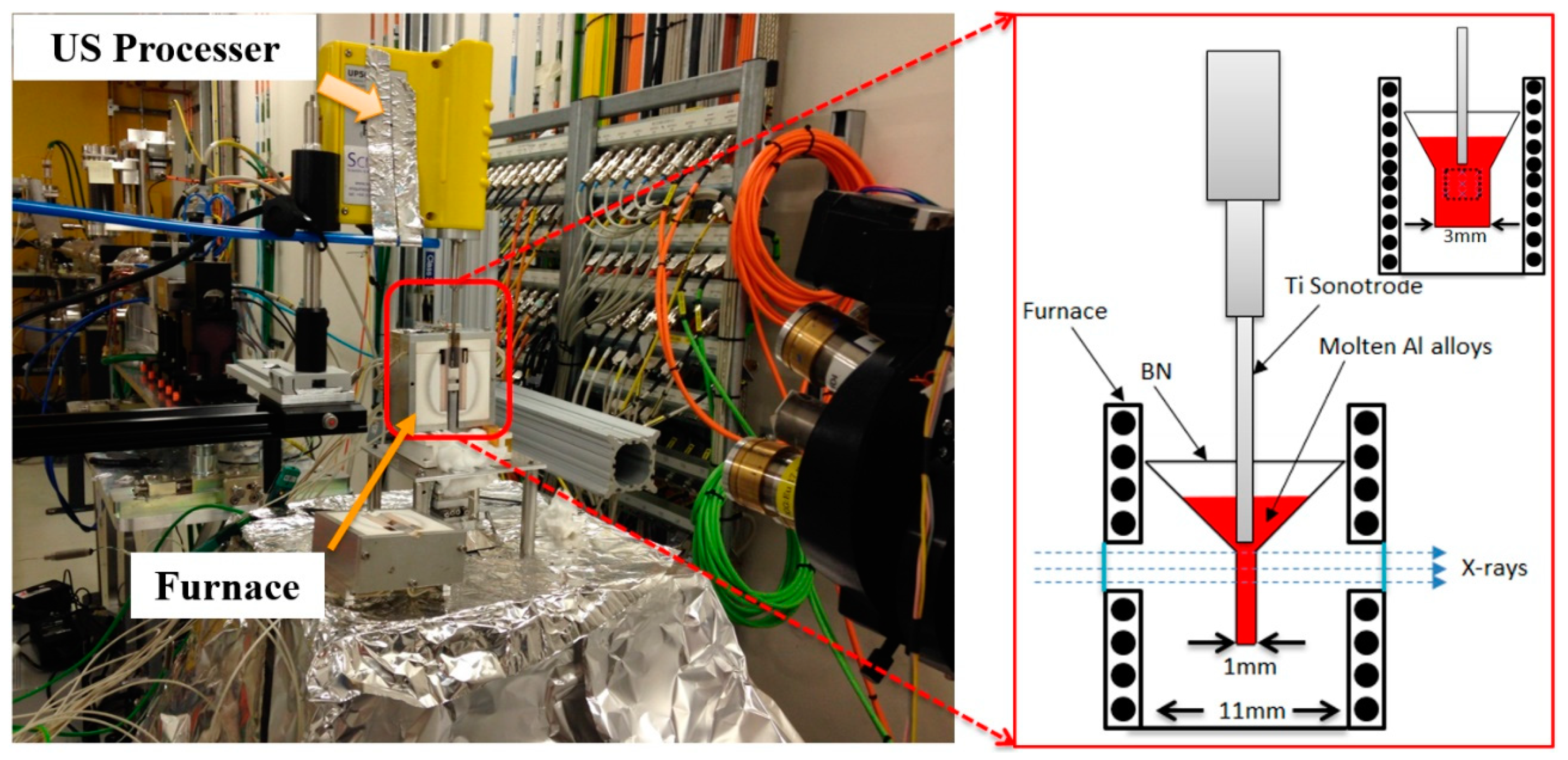
Nevertheless, there are some in situ imaging experiments focused on the observation of cavitation bubble dynamics in molten metal with and without the presence of nanoparticles [120]. The influence of nanoparticles on the molten metal and cavitation bubbles can then be revealed through comparisons. In a recent experiment, the in situ synchrotron X-ray radiographic imaging of ultrasound cavitation in a molten Al-10 wt% Cu with and without the addition of Al2O3 nanoparticles (0.05 wt%, mean size about 80 nm) was carried out [120]. As shown in Figure 16, references [114,118,120] show the experimental setup of ultrasonic processing of molten nanocomposite system mainly consists of a furnace, crucible, and an ultrasonic probe (integrated with an ultrasound processer) generating adequate processing power inside the melt [122]. This work demonstrated that the number density of cavitation bubbles was increased two-fold when the nanoparticles were presented in the molten metal [120], implying that the introduction of nanoparticles provided a large number of heterogeneous nuclei for cavitation bubbles. It is then reasonable to hypothesize that the collapses of those cavitation bubbles may strongly impact the nearby clustered nanoparticles. Consequently, deagglomeration of those nanoparticle clusters may be achieved through ultrasonic transient cavitation. In addition, approximately 20% increased acoustic streaming or flow rate was observed in the Al-10wt%Cu melt with an addition of 0.05 wt% Al2O3 nanoparticles [120]. The higher flow velocity caused by the greater ultrasonic field may increase the turbulent nature of the molten nanocomposite system [120]. The increased agitation in the melt may contribute to the deagglomeration of nanoparticles though re-agglomeration might also happen depending on the local flow patterns [120].
Despite very few experiments having been reported on the in situ imaging of ultrasonic deagglomeration process, a great number of ex situ trials have been performed to study the effect of ultrasonic melt treatment on the deagglomeration of nanoparticle clustering. This is usually to compare the microstructure and/or mechanical properties of the solid nanocomposite at ambient temperature before and after ultrasonic melt treatment [116]. Microscopically, the reduced size of nanoparticle clusters or more homogenous distribution of nanoparticles in the resultant nanocomposite represents the effectiveness of the ultrasonic melt treatment. As a result, mechanical properties of the metal matrix nanocomposite are enhanced [8,21]. In the nanocomposites processed by ultrasonic melt treatment, metal matrices are largely focused on aluminum [116,117,123,124,125,126,127,128], magnesium alloys [6,129,130,131], and transition metal alloys [8]. Typical nanoparticle reinforcers [8,132,133,134] include SiC, Al2O3, and various carbon polymorphs (e.g., graphene, carbon nanotubes, and diamond nanoparticles). During ultrasonic melt processing, nanoparticles, on the one hand, act as heterogeneous nucleation sites for cavitation bubbles and, on the other hand, alter the physical properties of the metal melt. The viscosity of the molten metal nanocomposite system increases significantly with the increase of the volume fraction of nanoparticles [135,136], thus strongly impacting the ultrasonic melt processing as well as the dynamics of cavitation bubbles in molten metal nanocomposites. Typically, a limited volume fraction of nanoparticles (up to ~5 vol% [21,137]) in the molten metals can be effectively dispersed by the ultrasonic melt treatment [136,137]. Prior studies also reported that the ultrasonically deagglomerated nanoparticles may re-agglomerate and then segregate after ultrasonic processing stops, mostly due to the attractive van der Waals forces between nanoparticles [137,138].
In view of the aforementioned experimental challenges, it is difficult to achieve direct imaging about the dynamic impact of ultrasonic cavitation bubbles on the nanoparticle clusters in molten metals. Modeling is, thus, often utilized to provide in-depth understanding of this process. The effect of ultrasonic cavitation in the melt on deagglomeration and the rate of deagglomeration can then be studied symmetrically. For example, the ultrasonic intensity (I) required for breaking up a nanoparticle agglomerate that is located at the front of a ultrasound wave in a molten metal, can be estimated by [116]:
I = 2 W L ( σ D ω ρ L ) 2
where is it assumed that the nanoparticle agglomerate is of spherical shape with a diameter of D. In Equation (4) σ is the tensile strength of an agglomerate beyond which agglomerate fractures. W L is the acoustic power introduced in the liquid and ρ L liquid metal density. ω is the ultrasonic frequency. Obviously, with the reduction of agglomerate size D (below ~40–50 µm), the deagglomeration force generated by certain frequency ultrasound (on the order of kHz) increases sharply [116]. In the case of aluminum melt with the introduction of Al2O3 nanoparticles, modeling of the deagglomeration process using Equation (4) is in good agreement with experimental measurements [21,116].
In order to simulate the dynamic process of breaking up of nanoparticle clusters [139,140] during ultrasonic cavitation, mesoscopic-scale modeling based on multiphase (fluid and solid) granular flow model [141,142,143] have been developed. For example, modeling with the coupling of computational fluid dynamics (CFD) and discrete element method (DEM) has been carried out for a number of nanocomposite systems, including aluminum- and magnesium-based alloys with the addition of SiC or Al2O3 nanoparticles [139]. The DEM-CFD modeling demonstrates that the high velocity pulses caused by the collapsing of cavitation gas bubbles during the ultrasonic treatment are capable of breaking up the agglomerates [139]. The deagglomeration is highly dependent on the interfacial energy between nanoparticles and liquid metals, the duration and the maximum value of the velocity pulse, as well as the size of the nanoparticle agglomerates [139,140]. The deagglomeration rate of a nanoparticle clusters can be quantified [140] as the average distance from particles that initially belonged to the cluster to their geometrical center, scaled by the particle radius:
Δ = 1 R np N np i | x i ¯ 1 N np i x j ¯ |
where Nnp is the number of nanoparticles in a cluster, Rnp is the radius of nanoparticle, xi denotes the position and bar is for the vector notation. In addition, mesoscale modeling has been employed to simulate the effect of acoustic streaming (or ultrasonic stirring) on the deagglomeration process of nanoparticle clusters in molten metals. For example, CFD coupled with the dense discrete phase model (DDPM) was applied to simulate the dynamic process of nanoparticles injection into the cavitation region in the molten metals. In a simulation of injecting SiC or Al2O3 nanoparticles (up to 1.0 wt%) into the molten A356 aluminum alloy, the nanoparticles are distributed well in the fluid after 3 s of ultrasonic melt treatment [124,144]. Obviously, the intense flow convection induced by the ultrasonic cavitation plays an important role in the deagglomeration and dispersion of ceramic nanoparticles in molten metals [143,144].

5. Strengthening Mechanisms

The strengthening mechanisms in the context of MMNCs are briefly introduced here. The effects that ceramic nanoparticles have on yield strength always include some different strengthening mechanisms that can act in varying degrees. The contributions to the strength increase can be summed up (Equation (6)) or the root of the sum of the squares can be regarded as an overall effect (Equation (7)). The summation method is used when the effects are assumed to be independent of each other, while the root of the sum of the squares is used when the individual effects do not act independently, the latter being more the case with larger particles. It is Δ σ Total , the total increase in yield strength; Δ σ GR , the yield strength increase caused by grain refinement; Δ σ OR , the Orowan contribution to yield strength increase; Δ σ CTE , the contribution to yield strength increase due to generation of geometrically necessary dislocations (GND), that are created during cooling due to mismatch of coefficient of thermal expansion (CTE) of particles and metal matrix; Δ σ Mod , the contribution to yield strength increase due to generation of GNDs, that are created during deformation due to different elastic moduli in a deformation process after casting; and Δ σ Load , the contribution to yield strength increase due to the simple presence of a reinforcement particles with higher strength, being well bonded to the surrounding matrix.
Δ σ Total = Δ σ GR + Δ σ OR + Δ σ CTE + Δ σ Mod + Δ σ Load
Δ σ Total = Δ σ GR 2 + Δ σ OR 2 + Δ σ CTE 2 + Δ σ Mod 2 + Δ σ Load 2
The individual contributions to increasing the yield strength will be discussed in more detail below.

5.1. Orowan

Orowan strengthening is based on hard particles that are distributed as homogeneously as possible in the matrix. These particles hinder the smooth movement of dislocations through the matrix on its slip planes. Typically, this effect can be neglected for particles with a diameter >1 µm [145]. When the dislocations interact with a particle, they first bend around the particle. Furthermore, the dislocations on the other side reconnect with themselves and form a dislocation loop around the particle which lead to an increase in strength. The dislocation itself can then continue to propagate through the matrix. The increase in strength is inversely proportional to the interparticle distance; therefore, the smaller the particles are, the higher the strength increase that can be achieved with the same proportion by volume or weight of particles. Equation (8) describes the contribution to the strength increase by Orowan strengthening [146] and Equation (9) describes the geometric description of the interparticle distance λ [147]. It is b the Burgers vector, Gm the shear modulus, dp the average diameter of the nanoparticles, Vp the Volume fraction of nanoparticles.
Δ σ OR = 0 . 13 bG m λ ln d p 2 b
where
λ = d p [ ( 1 2 V p ) 1 3 1 ]
AZ91D reinforced with 1 wt% AlN nanoparticles has been produced using an ultrasound-assisted casting process wherein the yield strength of the two materials with and without AlN nanoparticles is 144 and 100 MPa, respectively; Cao et al. [26] attributing this 44% increase to Orowan strengthening and calculated its theoretical contribution to be 35.8 MPa, whereas the missing 8.2 MPa is explained by a small grain refining effect of the nanoparticles.
A composite material based on an Mg-2Zn alloy with an SiC nanoparticle content of 14 vol% [137] was obtained via ultrasound-assisted casting of an Mg-6Zn alloy with a SiC particle content of 1 vol% SiC followed by evaporation of Mg and Zn. Orowan strengthening as a component of the increase in yield strength is calculated to be 113 MPa. The high value is a result of the small interparticle distance of such a high volume fraction of SiC nanoparticles.

5.2. Hall–Petch

The addition of ceramic particles or the primary precipitation of phases during solidification can lead to a grain refinement of the microstructure. In magnesium alloys, for example, zirconium is used for grain refinement, which can reduce the grain size in aluminum-free casting alloys by one order of magnitude. The addition of nanoparticles can therefore also lead to an increase in yield strength, which can be attributed to grain refinement. This increase in yield strength is described in Equation (10), called the Hall–Petch equation [148,149] where σy is the yield strength, σ0 is the friction stress that allows dislocations to move on slip planes in a single crystal in the absence of any strengthening mechanisms, ky is the stress concentration factor, and D is the average grain size.
σ y = σ 0 + k y D - 1 / 2
The increase in yield strength can also be expressed by Equation (11), premised that grain refinement was achieved by nanoparticles and exactly the same casting process was used as for the unreinforced alloy [150]. DMMNC and D0 are the grain sizes of the nanocomposite and the unreinforced alloy.
Δ σ GR = k y ( 1 D MMNC 1 D 0 )
The grain refining effect of the introduced nanoparticles is very clearly illustrated when, as a part of the EU project EXOMET, a die-casting alloy AM60 was reinforced with 1 wt% AlN nanoparticles [127]. The AM60 is a commercial alloy used in the automotive industry from which, for example, steering wheels, seat frames, or housings are die-cast. The components have very good room temperature strength and ductility.
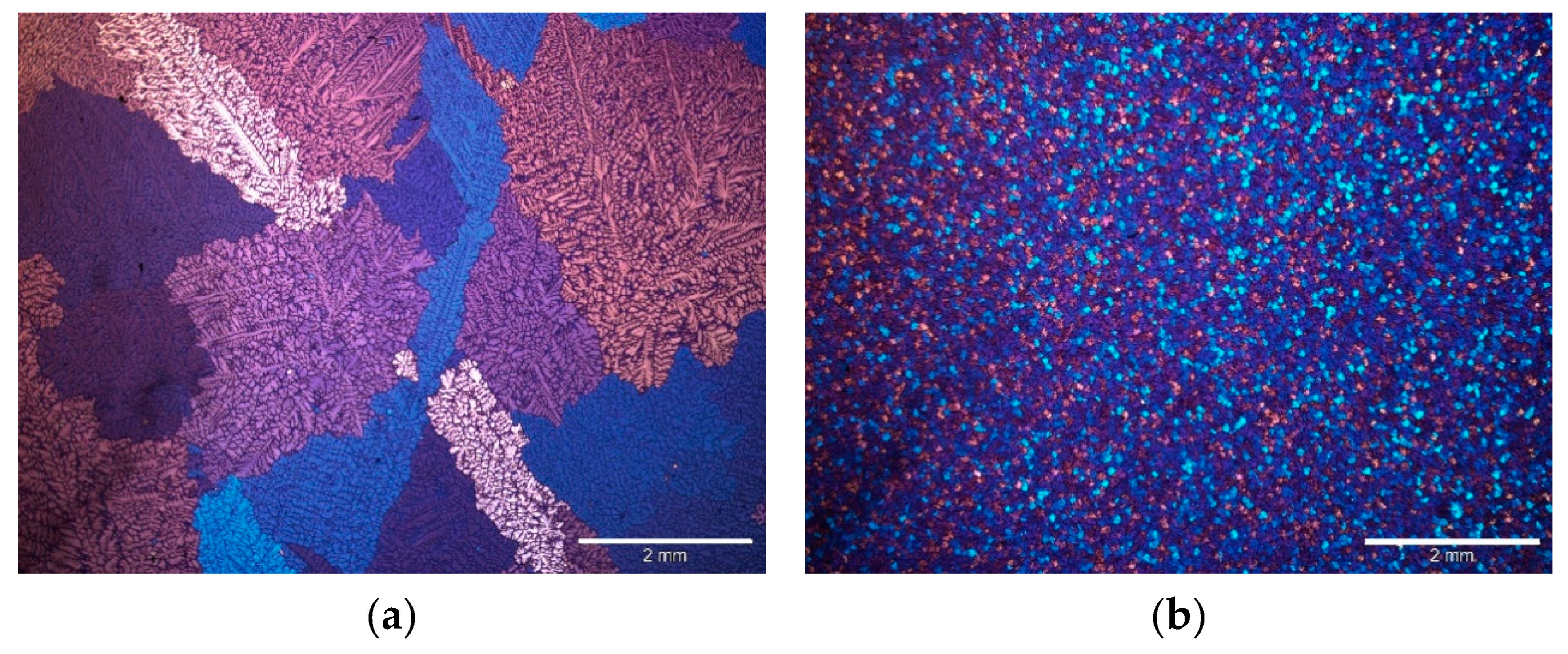
The AM60-based nanocomposite was produced using an ultrasound-assisted casting process. After adding the nanoparticles, the melt was stirred and an ultrasonic sonotrode was immersed in the melt, which emits sound at a frequency of 20 kHz. As can be seen in Figure 17, an immense grain refinement of the microstructure could be achieved by adding the AlN nanoparticles. Since both materials were produced identically, grain refinement is therefore only due to the presence of nanoparticles; a change from 1277.0 ± 301.3 µm to 84.9 ± 6.2 µm doubles the yield strength (+103%) and tensile strength (+115%), see Table 4, while the ductility at the same time was increased by 140% from 6.4 to 15.4% [127].
Calculations have shown that the contribution of grain refinement to the yield strength increase is the largest with 42.7 MPa, followed by the contribution of Orowan strengthening with 8.3 MPa; other contributions to the increase in strength are negligible. All properties are summarized in Table 4.
As already mentioned in Table 1, AlN has a hexagonal structure with lattice constants of a = 0.311 nm and c = 0.498 nm. These are very similar to those of magnesium (a = 0.321nm and c = 0.512 nm), which leads to an easy growth of magnesium on an AlN nucleus during solidification [86]. No large strains of the lattice are required and the differences in the lattice constants can be overcome after a few layers of deposited magnesium. Close matching between the AlN and Mg lattices is illustrated in Figure 18.

5.3. Mismatch in the CTE

When a nanocomposite is produced by stirring nanoparticles into a metallic melt, the material cools down to room temperature after solidification. Since the nanoparticles and the metallic matrix usually have significantly different coefficients of thermal expansion (CTEs), stresses occur at the interface. The more different the CTEs are, the higher the stresses, which then generate geometrically necessary dislocations (GND) with which the differences of the CTEs can be accommodated. Similar to cold-working, GNDs increase the yield strength of the composite which can be calculated using the Equation (12) [151,152]. The expression below the square root represents the density of the dislocations generated by the CTE difference where β is the dislocation strengthening coefficient, Δα the difference in CTE, and ΔT the difference in temperature.
Δ σ CTE = 3 β G m b 12 V p Δ α Δ T bd p
It should be mentioned, however, that during the cooling from high temperature, diffusion processes can also compensate the stresses and no GNDs may be generated [153]. Furthermore, there is also evidence that the contribution of very small particles to the increase in strength due to CTE mismatch is rather negligible [153,154].

5.4. Mismatch in the Young’s Modulus

GNDs can be generated not only by differences in the thermal expansion coefficients between nanoparticles and the metallic matrix, but also by differences in the Young’s modulus. For this, however, forming processes such as extrusion, rolling, or forging must have been applied to the nanocomposite. The different Young’s moduli generate GNDs during forming, which then increases the yield strength. Dai et al. [151] suggests Equation (13) to calculate the contribution of the difference in Young’s modulus to the increase in strength of the α material coefficient and the ε bulk strain of the composite.
Δ σ Mod = 3 α G m b 6 V p ε bd p

5.5. Load-Bearing

The load-bearing-mechanism as a strengthening mechanism in MMNCs sets the yield strengths of the nanoparticles and the metallic matrix in a volume-dependent relationship to each other. However, since nanocomposites typically contain only very low volume contents of nanoparticles, the influence of this mechanism is small, as Equation (14) also shows [155]; σm is the yield strength of the matrix.
Δ σ Load = 1 2 V p σ m

6. Mechanical Properties

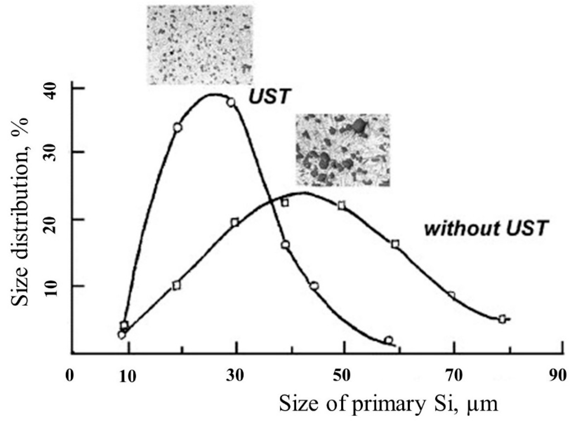
Enhanced mechanical property is the main goal for most of MMNCs. Among different techniques, ultrasonic-assisted fabrication of metal matrix nano-composites (MMNCs) offers significant opportunities for developing structural materials possessing improved mechanical properties which are not achievable by conventional casting process. For example, ultrasonic treatment can provide uniform dispersion, as well as finer Si particle in the Al-17 wt% Si alloy, as shown in Figure 19 [105]. The wide selection of matrices (predominantly Al, Mg, and Cu), and reinforcements (carbides, oxides, and carbonaceous particles) permits the development of MMNCs with attractive mechanical properties, such as high tensile strength, creep, and fatigue resistance [117,123,126,129,131,156].
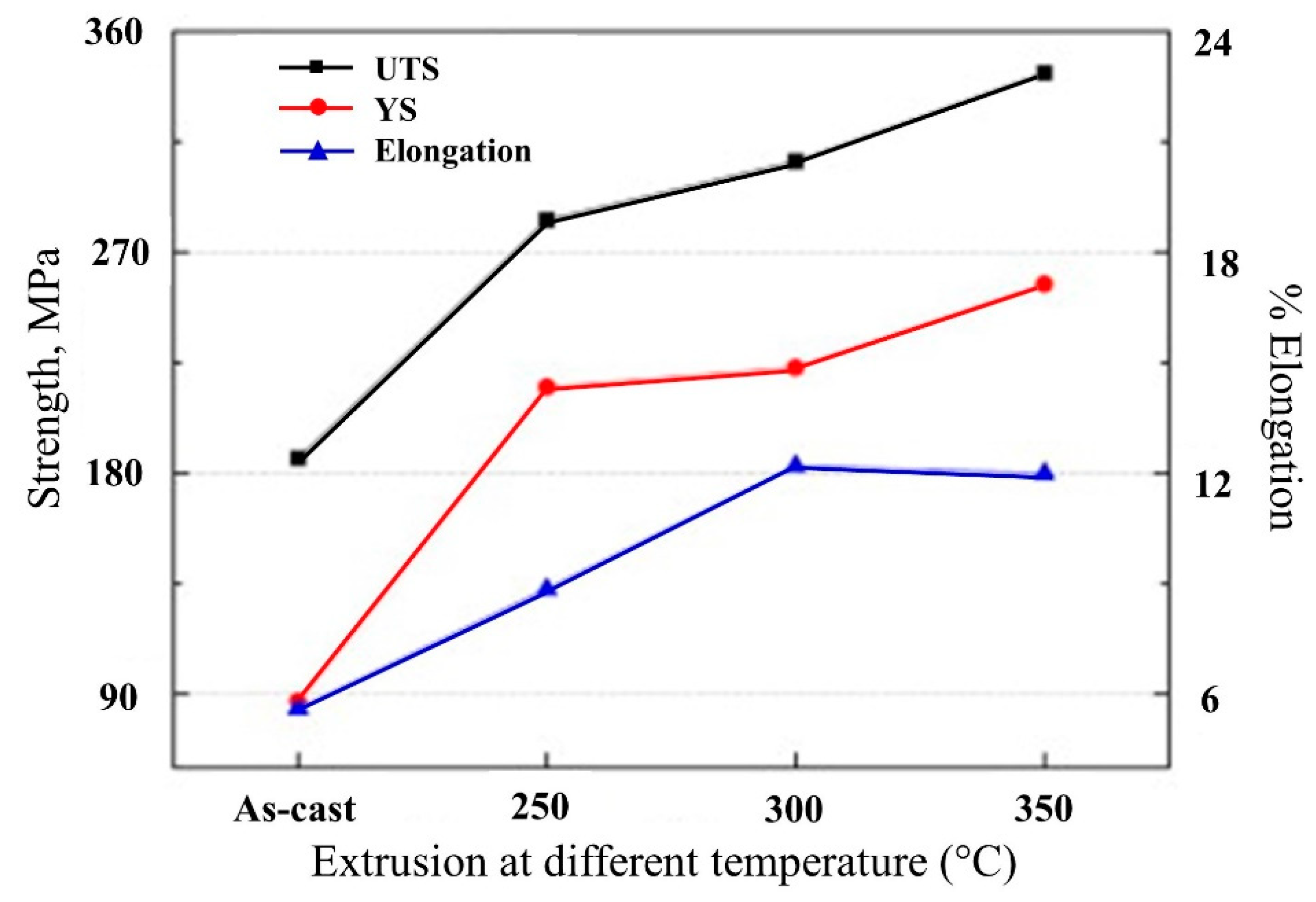
Lan et al. [131] produced the SiC/Mg alloy (AZ91D) composites using ultrasonic-assisted casting. A good dispersion of the 30 nm SiC was observed although some clusters (~300 nm) of SiC still existed, which authors contend may be due to the partial oxidation of SiC leading to this clustering during casting. However, the 5 wt% SiC reinforcement improved the microhardness by 75%. The same Mg alloy (AZ91D) matrix reinforced with 1 wt% of nano AlN improved the yield strength by 44% and 21% at room temperature and 200 °C, respectively, compared with unreinforced AZ91D alloy while the ductility remained the same [26]. In the microstructure of the composite, the finer lamellar β phase has also been observed that suggests that nanoparticles can also refine the microstructure and improve the mechanical properties. Nie et al. [157] revealed the improved ductility in the extruded AZ91D Mg alloy reinforced with 0.5 wt% of 50 nm SiC. The yield strength, UTS, and elongation were increased for the composites extruded at different temperatures, as shown in Figure 20; extrusion at 350 °C was the most beneficial because of higher UTS and yield strength (YS), as well as improved ductility.
In yet another similar fabrication process, the addition of 1 wt% SiC in Mg-4Zn alloy increased the UTS and elongation twice compared to unreinforced alloy attributed to the presence of nano-SiC as grain refinement; similar improvements in mechanical properties due to the presence of nanoparticles and grain refinement by ultrasonic treatment has been documented in other studies [126,129,158,159].
TiB2 is also a promising reinforcement due to its high melting point and thermodynamic stability, especially in Al matrix where it has no interface reaction with Al. Ultrasonic-assisted casting of 5 vol% TIB2/Al-4.5Cu improved the yield strength by 100% while the ductility is reduced by 100%. Ultrasonic dispersion has also been able to disperse carbon nanotubes (CNTs) in Mg alloy (AZ91D) that was not attainable by stir casting without ultrasonic assistance and using a dispersion agent due to the strong interface between CNTs and matrix [156]; the ensuing composite with 1.5 wt% CNTs has improved tensile strength, yield strength, and elongation by 22%, 21%, and 42%, respectively, compared with AZ91D magnesium alloy. Additional studies on MMNCs via ultrasonic-assisted fabrication are listed in Table 5 along with the reinforcement material content and percentage improvement in the tensile properties.
The introduction of ultrasonic waves also depends on the casting process, the most common being stir-casting and squeeze-casting process. Singh et al. [160] compared these two processes on the mechanical properties of AA 6061 Al alloy reinforced with nano Al2O3 particles (Figure 21). It can be seen that the tensile strength (Figure 21a) and hardness (Figure 21b) of composites fabricated by ultrasonic-assisted squeeze-casting is higher than the stir casting process. The authors suggested that the application of pressure during the squeeze-casting process combined with ultrasonic waves provided finer dendritic structures which culminated in higher mechanical properties compared to ultrasonic-assisted stir-casting. This study also revealed that the ultrasonic waves during both the casting processes were able to avoid agglomeration of nano-Al2O3 particles. However, for those samples reinforced by higher weight fraction (>2 wt%), tensile strength begins to decrease due to the clustering and agglomeration of nanoparticles.
It has been also observed that the bonding between the matrix and reinforcement plays an important role for mechanical properties, such as γ-Al2O3 having a higher lattice mismatch compared to α-Al2O3. The higher lattice mismatch of γ-Al2O3 resulted in a better nucleation catalyzer in A356 alloy during ultrasonic-assisted casting because it requires less under-cooling [161]. It has also been observed that uniform dispersion of nanoparticles in the metal matrix by ultrasonic-assisted casting provides a finer microstructure that helps to either maintain or improve the ductility of composites.
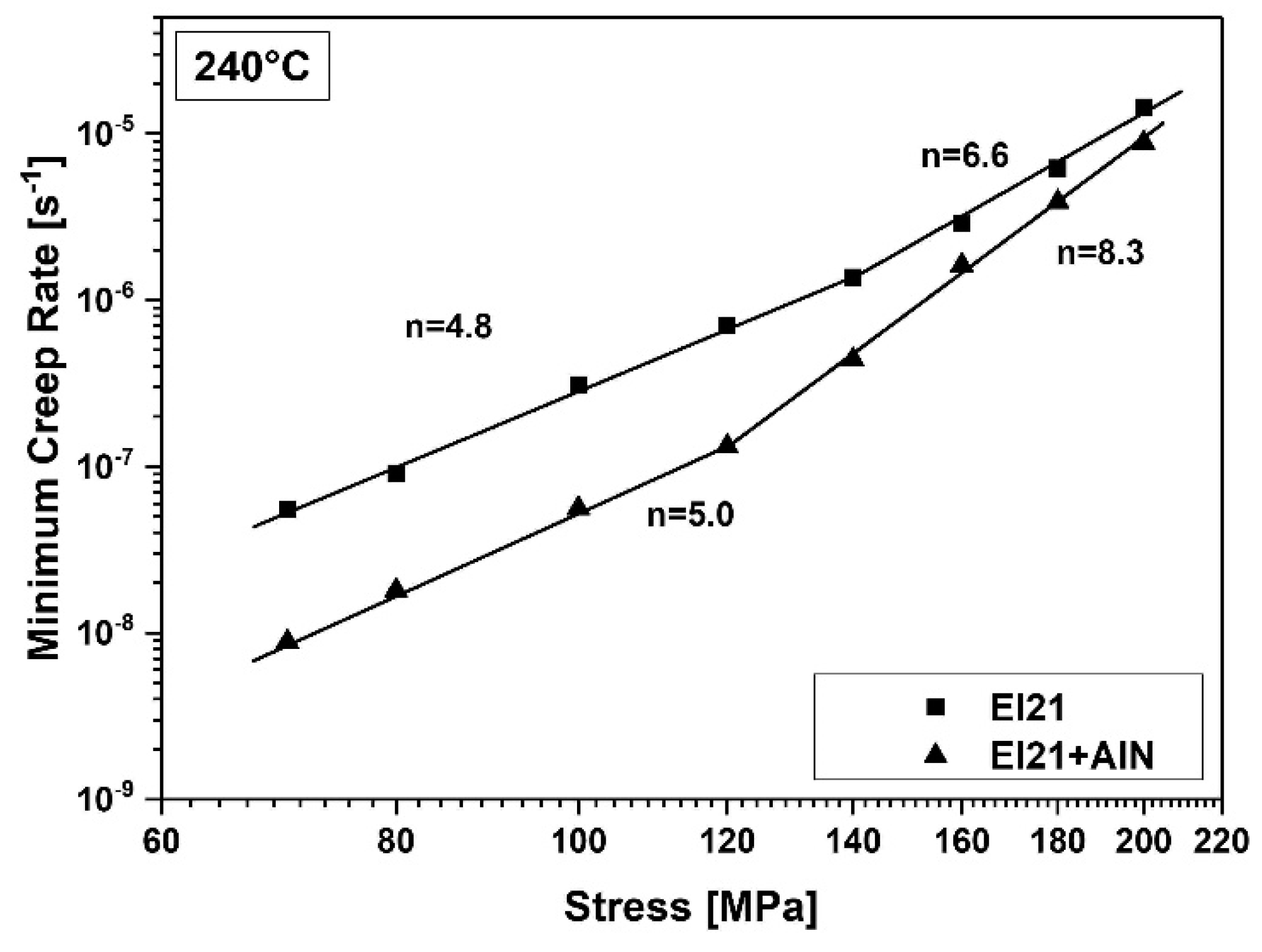
Other mechanical properties, such as fatigue, creep, etc., have not been studied significantly to understand the influence of ultrasonic-assisted casting. One of the studies on 1 wt% AlN reinforced Mg alloy (Elektron21, Mg-2.8Nd-1.2Gd-0.4Zr-0.3Zn) showed improvement in the creep properties, as shown in Figure 22 [128]; the reinforced Mg alloy (El21) showed a lower creep rate compared to unreinforced Mg alloy. However, further studies have to be conducted on different matrices and reinforcements to bring out the beneficial effect of ultrasonic treatment during casting that can alter the other mechanical properties, including fatigue, creep, damping, etc.
Casting processes are beneficial in industrial settings due to easy adaption on large-scale production. However, the potential nano additives for MMNCs, namely graphene (Gr) and carbon nanotubes (CNTs), have poor wetting behavior during liquid mixing [95], a limitation that leads to utilization of the powder metallurgy (PM) route that involves solid-state processing. Several Al, Cu, Ni, and Ti matrix composites reinforced with graphene and CNT have been produced via powder metallurgy with superior mechanical properties [8,169]; some composites are listed in Table 6 along with their mechanical and tribological properties. It has been observed that during high temperature sintering, carbonaceous materials react with matrix and forms carbides, such as aluminum carbide in the case of Al matrix, which reduces the mechanical properties of composites [170,171]. To overcome this concern a rapid sintering process, such as laser sintering, has been used that has improved the mechanical properties of the composites [170,172]. These studies suggest that the PM route provides an alternative to the casting process, especially for the production of small components because the PM route generates finished products.

7. Tribological Properties of MMNCs

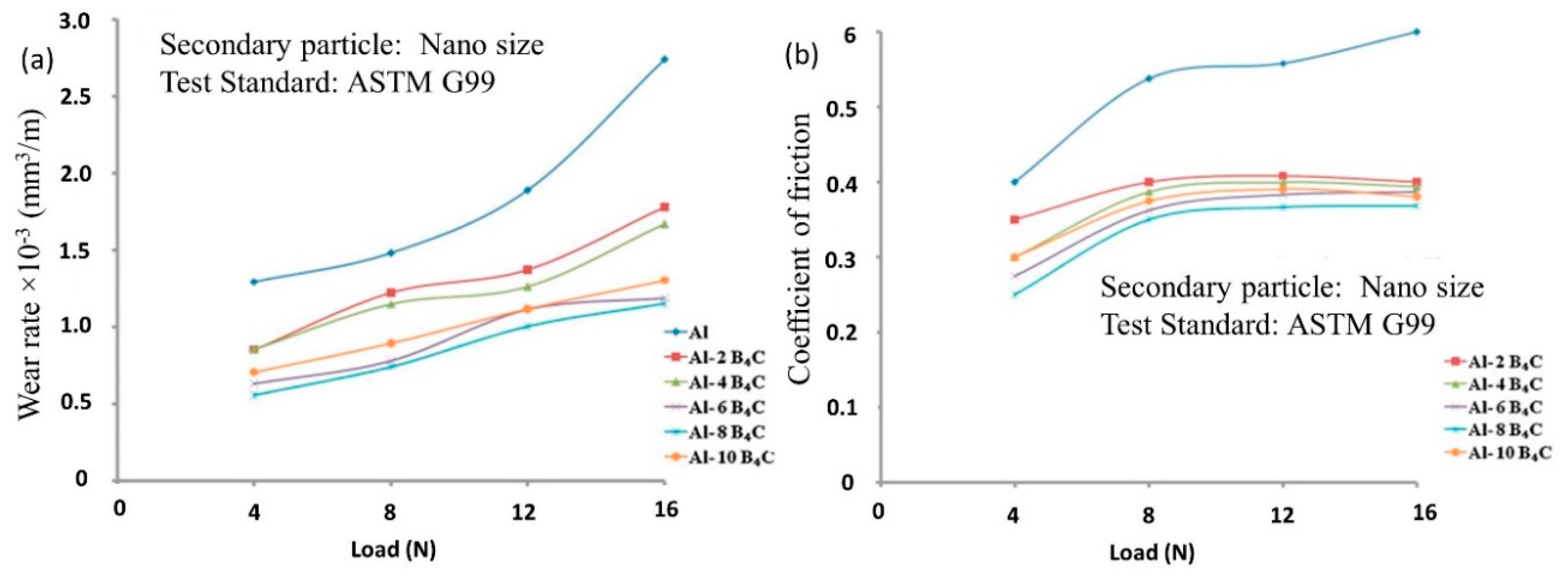
MMNCs display superior tribological properties, such as surface hardness and wear resistance [95,122,184,185,186]. Ultrasonic treatment has been advantageous to enhance the surface properties by uniform dispersion of nanoparticles and avoid the formation of porosity. Improvement in the surface hardness by 75% has been achieved with a reinforcement of 5 wt% of SiC in Mg alloy (AZ91D) by ultrasonic-assisted casting [131]. Using a similar casting process, Li et al. [122] observed a 20% hardness improvement in Al 356 alloy with the addition of 2 vol% SiC nanoparticles. However, very few studies have been conducted on the tribological properties of MMNCs produced by ultrasonic-assisted casting. In one of the studies on Al alloy, Harichandran et al. [187] produced the nano B4C-Al composite by ultrasonic-assisted stir casting and conducted the dry sliding friction and wear test against EN31 hardened steel; the addition of 8 wt% B4C decreased the wear rate by ~100% compared with pure Al (Figure 23a). The coefficient of friction has also decreased with the addition of B4C in Al, as exemplified for Al-8 wt% B4C composites (Figure 23b). This lowering of the wear rate and the coefficient of friction was observed due to formation of a mechanically mixed layer during sliding, and such a layer acted as a solid lubricant film and protected the surfaces. B4C-AA6061 composites were fabricated by ultrasonic-assisted casting [188] and, where the friction and wear were measured; AA6061 reinforced with 1.5 vol% of nano B4C particle had lower weight loss (136% lesser than the unreinforced AA6061 alloy) possibly due to the improved hardness by the uniform distribution of nanoparticles that served as load-bearing elements in the matrix.
Zinc-aluminum (ZA) cast alloys, known for good castability and high wear resistance, have been reinforced with nano-sized Al2O3 particles using ultrasonic-assisted stir casting [189]. Three different composites with varying amount of reinforcement (1, 2, and 3 wt%) were prepared and evaluated via the dry sliding test for a range of speed (1–2.5 m/s), load (15–60 N), and sliding distance (750–3000 m), and the wear loss was analyzed using the analysis of variance (ANOVA) to understand the significance of aforementioned parameters on wear volume. It was observed that the most important influencing parameter was sliding distance with percentage contribution (74%) followed by reinforcement content (14.4%), speed (6.5%), and load (3.5%). The higher contribution from reinforcement suggests that nano-Al2O3 reduced the wear volume. Other than tribological test parameters and reinforcement content, the size of the nano-reinforcement is also important to study wear resistance. Murthy et al. [168] studied the effect of SiC particle size (0.5, 1, 1.5, and 2 wt%) on stir-casted AA2219 nanocomposites fabricated by the ultrasonic-assisted process; 50 nm and 250 nm sizes of SiC were used in the matrix with the observation that the 50 nm SiC-AA2219 had 25% lower wear volume compared with the 150 nm SiC-AA2219 composites. These results also reaffirmed that ultrasonic fabrication can certainly provide uniform reinforcement of a wide range of nanoparticles sizes and improves the tribological properties.
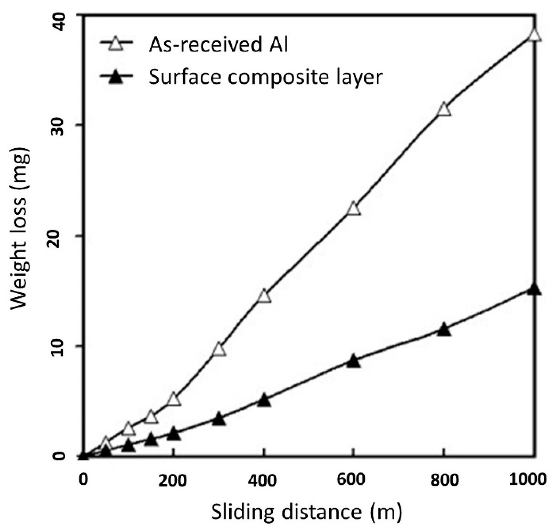
In general, wear properties of materials are related to surface hardness; higher surface hardness provides increased wear resistance. Shafiei-Zarghani et al. [56] also corroborated the same trend by witnessing that the addition 20 vol% of Al2O3 (50 nm) in 6082 Al alloy increased the hardness by ~78%, which subsequently resulted in lower weight loss when sliding against tool steel (Figure 24). However, in this work, the ultrasonic treatment was not used and clusters of Al2O3 particles of 90 nm size were observed. It can be envisaged that addition of ultrasonic waves during casting can avoid clustering and provide a further increase in the wear properties. These studies suggest that ultrasonic-assisted fabrication is a promising technique to disperse nanoparticles and achieve significant improvement in the tribological properties.
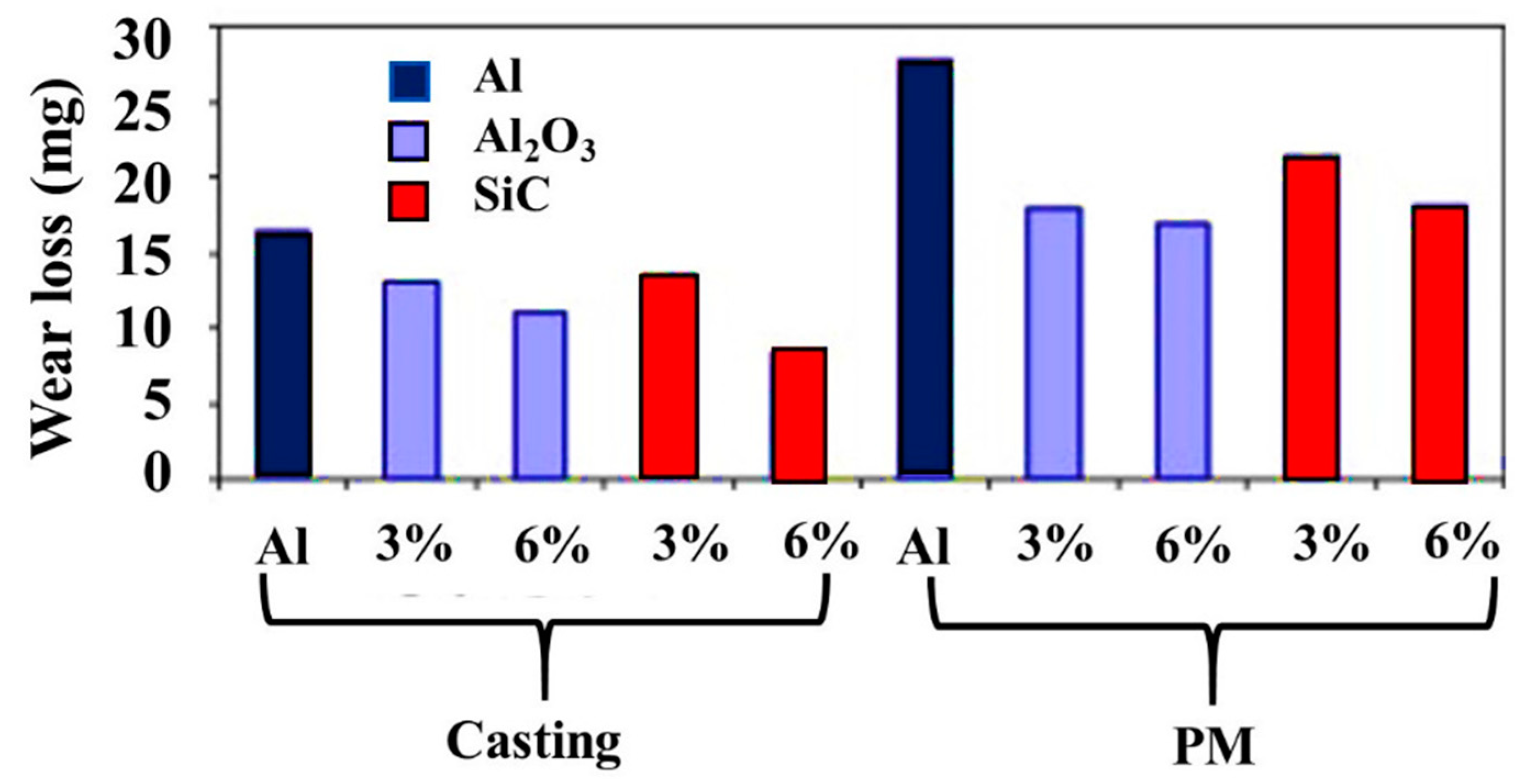
Carbonaceous materials are well known for their lubricating properties via the formation of a tribo layer that reduces the friction [95,190] and, as described before, PM routes are often deployed when CNTs and graphene are used as reinforcement. Some of the composites listed in Table 1 show a high reduction in COF and lower wear rate. However, for SiC- and Al2O3-reinforced Al composites, Ünlü et al. [191] have noticed that casting process yields superior mechanical and tribological properties than the PM process; the tensile, compressive, and hardness values of casted composites were 1.5–2 times higher than the respective values of composites synthesized by the PM process due to less porosity. Similarly, both types of composites (Al2O3 and SiC) prepared by casting showed lower wear compared to composites prepared by the PM route, as shown in Figure 25. This concludes that it is advantageous to use the PM route for carbonaceous materials, whereas the casting route should be preferred for all other oxides/carbides.

8. Conclusions, Current Challenges, and Future Remarks

Metal matrix nanocomposites (MMNCs) are lightweight, high-strength materials that have found widespread use in a wide variety of industrial and biomedical applications. A matrix usually comprising a lightweight metal, such as aluminum or magnesium, is reinforced by a variety of high-strength nano-particles, namely nano-ceramics, nano oxide/non-oxides, carbon-based nano-allotropes, elements, etc. This review aims to provide comprehensive information about the manufacturing methods, nano-reinforcing agents, dispersion mechanisms (such as cavitation de-agglomeration), underlying strengthening mechanisms, and the effects of different process parameters on mechanical, microstructural, and tribological properties.
The selection of synthesis techniques and process parameters are critical for developing MMNCs with superior properties; stir casting, disintegrated melt deposition, accumulative role bonding, and powder metallurgy are some of these most prevalent processing techniques. Among the methods, special attention has been paid to the liquid-based manufacturing processes where a homogenous good dispersion of nanoparticles in the melt is still a very challenging proposition in view of poor wettability between nano-particles and the metal host. Although the dispersing techniques (e.g., melt ultrasonication) during casting/solidification is advantageous to avoid agglomeration and enhance wetting conditions, there is still a paucity of experimental or simulation studies available to suggest the best dispersing conditions. Direct in situ imaging of deagglomeration of nanoparticle clusters in molten metals will provide a clear insight about the processing, mechanisms, and parameters of the advanced metal matrix nanocomposites. Such experiments can provide precise understanding of the deagglomeration dynamics under certain treatment processing besides large-scale atomistic modeling, which may also offer similar understanding. The hurdle is that the chemical potentials of the interfacial atoms between liquid metal alloys and ceramic nanoparticles are usually not available owing to the charge re-distribution at the liquid metal/solid nanoparticle ceramics, which can only be determined by quantum mechanics. Thus, in the future, quantum-based chemical potentials for various MMNCs systems need to be developed so that large-scale atomistic modeling can be performed to study the deagglomeration dynamics. Moreover, from the industrial perspective, the upscaling of reliable processes for industrial application of MMNCs is presently one of the most challenging issues that needs to be investigated in future activities. Finally, MMNCs are usually processed under lab-scale conditions; a continuous industrial scale has not yet been developed, wherein the melt flows into a mold and nanoparticles are continuously homogenously dispersed to reinforce the metal matrix.

Conflicts of Interest

The authors declare no conflict of interest.

References

  1. Ibrahim, I.; Mohamed, F.; Lavernia, E. Particulate reinforced metal matrix composites—A review. J. Mater. Sci. 1991, 26, 1137–1156. [Google Scholar] [CrossRef]
  2. Kim, Y.; Lee, J.; Yeom, M.S.; Shin, J.W.; Kim, H.; Cui, Y.; Kysar, J.W.; Hone, J.; Jung, Y.; Jeon, S. Strengthening effect of single-atomic-layer graphene in metal–graphene nanolayered composites. Nat. Commun. 2013, 4, ncomms3114. [Google Scholar] [CrossRef] [PubMed]
  3. Ceschini, L.; Dahle, A.; Gupta, M.; Jarfors, A.E.W.; Jayalakshmi, S.; Morri, A.; Rotundo, F.; Toschi, S.; Singh, R.A. Aluminum and Magnesium Metal Matrix Nanocomposites; Springer: New York, NY, USA, 2017. [Google Scholar]
  4. Lloyd, D. Particle reinforced aluminium and magnesium matrix composites. Int. Mater. Rev. 1994, 39, 1–23. [Google Scholar] [CrossRef]
  5. Cha, S.I.; Kim, K.T.; Arshad, S.N.; Mo, C.B.; Hong, S.H. Extraordinary strengthening effect of carbon nanotubes in metal-matrix nanocomposites processed by molecular-level mixing. Adv. Mater. 2005, 17, 1377–1381. [Google Scholar] [CrossRef]
  6. Dieringa, H. Properties of magnesium alloys reinforced with nanoparticles and carbon nanotubes: A review. J. Mater. Sci. 2011, 46, 289–306. [Google Scholar] [CrossRef]
  7. Gupta, M.; Wong, W. Magnesium-based nanocomposites: Lightweight materials of the future. Mater. Charact. 2015, 105, 30–46. [Google Scholar] [CrossRef]
  8. Tjong, S.C. Recent progress in the development and properties of novel metal matrix nanocomposites reinforced with carbon nanotubes and graphene nanosheets. Mater. Sci. Eng. R Rep. 2013, 74, 281–350. [Google Scholar] [CrossRef]
  9. Huang, X.; Qi, X.; Boey, F.; Zhang, H. Graphene-based composites. Chem. Soc. Rev. 2012, 41, 666–686. [Google Scholar] [CrossRef] [PubMed]
  10. Riedel, R. Nanoscaled inorganic materials by molecular design. Chem. Soc. Rev. 2012, 41, 5029–5031. [Google Scholar] [CrossRef] [PubMed]
  11. Calvert, P. Nanotube composites: A recipe for strength. Nature 1999, 399, 210. [Google Scholar] [CrossRef]
  12. Flint, E.B.; Suslick, K.S. The temperature of cavitation. Science 1991, 253, 1397–1399. [Google Scholar] [CrossRef] [PubMed]
  13. Bang, J.H.; Suslick, K.S. Applications of ultrasound to the synthesis of nanostructured materials. Adv. Mater. 2010, 22, 1039–1059. [Google Scholar] [CrossRef] [PubMed]
  14. Abdullah, A.; Pak, A.; Abdullah, M.M.; Shahidi, A.; Malaki, M. Study of the behavior of ultrasonic piezo-ceramic actuators by simulations. Electron. Mater. Lett. 2014, 10, 37–42. [Google Scholar] [CrossRef]
  15. Abdullah, A.; Malaki, M. On the damping of ultrasonic transducersʼ components. Aerosp. Sci. Technol. 2013, 28, 31–39. [Google Scholar] [CrossRef]
  16. Abdullah, A.; Malaki, M.; Baghizadeh, E. On the impact of ultrasonic cavitation bubbles. Proc. Inst. Mech. Eng. Part C J. Mech. Eng. Sci. 2012, 226, 681–694. [Google Scholar] [CrossRef]
  17. Gupta, M.; Seetharaman, S. Magnesium Based Nanocomposites for Cleaner Transport. Nanotechnol. Energy Sustain. 2017, 809–830. [Google Scholar] [CrossRef]
  18. Gupta, M.; Meenashisundaram, G.K. Insight into Designing Biocompatible Magnesium Alloys and Composites: Processing, Mechanical and Corrosion Characteristics; Springer: New York, NY, USA, 2015. [Google Scholar]
  19. Gong, H.; Anasori, B.; Dennison, C.R.; Wang, K.; Kumbur, E.C.; Strich, R.; Zhou, J.G. Fabrication, biodegradation behavior and cytotoxicity of Mg-nanodiamond composites for implant application. J. Mater. Sci. Mater. Med. 2015, 26, 110. [Google Scholar] [CrossRef] [PubMed]
  20. Paul, W.; Sharma, C.P. Nanoceramic matrices: Biomedical applications. Am. J. Biochem. Biotechnol. 2006, 2, 41–48. [Google Scholar] [CrossRef]
  21. Eskin, G.I.; Eskin, D.G. Ultrasonic Treatment of Light Alloy Melts; CRC Press: Boca Raton, FL, USA, 2014. [Google Scholar]
  22. Hemanth, J. Development and property evaluation of aluminum alloy reinforced with nano-ZrO2 metal matrix composites (NMMCs). Mater. Sci. Eng. A 2009, 507, 110–113. [Google Scholar] [CrossRef]
  23. Hamedan, A.D.; Shahmiri, M. Production of A356–1 wt% SiC nanocomposite by the modified stir casting method. Mater. Sci. Eng. A 2012, 556, 921–926. [Google Scholar] [CrossRef]
  24. Sajjadi, S.A.; Ezatpour, H.; Beygi, H. Microstructure and mechanical properties of Al–Al2O3 micro and nano composites fabricated by stir casting. Mater. Sci. Eng. A 2011, 528, 8765–8771. [Google Scholar] [CrossRef]
  25. Suresh, S.; Mishra, D.; Srinivasan, A.; Arunachalam, R.; Sasikumar, R. Production and characterization of micro and nano Al2O3 particle-reinforced LM25 aluminium alloy composites. ARPN J. Eng. Appl. Sci. 2011, 6, 94–98. [Google Scholar]
  26. Cao, G.; Choi, H.; Oportus, J.; Konishi, H.; Li, X. Study on tensile properties and microstructure of cast AZ91D/AlN nanocomposites. Mater. Sci. Eng. A 2008, 494, 127–131. [Google Scholar] [CrossRef]
  27. Donthamsetty, S.; Damera, N.; Jain, P. Ultrasonic cavitation assisted fabrication and characterization of A356 metal matrix nanocomposite reiforced with Sic, B4C, CNTs. Asian Int. J. Sci. Technol. Prod. Manuf. Eng. 2009, 2, 27–34. [Google Scholar]
  28. Akbari, M.K.; Mirzaee, O.; Baharvandi, H. Fabrication and study on mechanical properties and fracture behavior of nanometric Al2O3 particle-reinforced A356 composites focusing on the parameters of vortex method. Mater. Des. 2013, 46, 199–205. [Google Scholar] [CrossRef]
  29. Gupta, M.; Ling, S.N.M. Magnesium, Magnesium Alloys, and Magnesium Composites; John Wiley & Sons: Hoboken, NJ, USA, 2011. [Google Scholar]
  30. Ezatpour, H.R.; Sajjadi, S.A.; Sabzevar, M.H.; Huang, Y. Investigation of microstructure and mechanical properties of Al6061-nanocomposite fabricated by stir casting. Mater. Des. 2014, 55, 921–928. [Google Scholar] [CrossRef]
  31. Alam, M.T.; Arif, S.; Ansari, A.H. Mechanical Behaviour and Morphology of A356/SiC Nanocomposites Using Stir Casting. In IOP Conference Series: Materials Science and Engineering; IOP Publishing: Bristol, UK, 2017; p. 012293. [Google Scholar]
  32. Khandelwal, A.; Mani, K.; Srivastava, N.; Gupta, R.; Chaudhari, G. Mechanical behavior of AZ31/Al2O3 magnesium alloy nanocomposites prepared using ultrasound assisted stir casting. Compos. Part B Eng. 2017, 123, 64–73. [Google Scholar] [CrossRef]
  33. Goh, C.; Wei, J.; Lee, L.; Gupta, M. Simultaneous enhancement in strength and ductility by reinforcing magnesium with carbon nanotubes. Mater. Sci. Eng. A 2006, 423, 153–156. [Google Scholar] [CrossRef]
  34. Srivatsan, T.; Godbole, C.; Paramsothy, M.; Gupta, M. Influence of nano-sized carbon nanotube reinforcements on tensile deformation, cyclic fatigue, and final fracture behavior of a magnesium alloy. J. Mater. Sci. 2012, 47, 3621–3638. [Google Scholar] [CrossRef]
  35. Ho, K.; Gupta, M.; Srivatsan, T.S. The mechanical behavior of magnesium alloy AZ91 reinforced with fine copper particulates. Mater. Sci. Eng. A 2004, 369, 302–308. [Google Scholar] [CrossRef]
  36. Goh, C.; Wei, J.; Lee, L.; Gupta, M. Ductility improvement and fatigue studies in Mg-CNT nanocomposites. Compos. Sci. Technol. 2008, 68, 1432–1439. [Google Scholar] [CrossRef]
  37. Goh, C.; Wei, J.; Lee, L.; Gupta, M. Properties and deformation behaviour of Mg–Y2O3 nanocomposites. Acta Mater. 2007, 55, 5115–5121. [Google Scholar] [CrossRef]
  38. Srivatsan, T.; Godbole, C.; Quick, T.; Paramsothy, M.; Gupta, M. Mechanical behavior of a magnesium alloy nanocomposite under conditions of static tension and dynamic fatigue. J. Mater. Eng. Perform. 2013, 22, 439–453. [Google Scholar] [CrossRef]
  39. De Cicco, M.P.; Li, X.; Turng, L.-S. Semi-solid casting (SSC) of zinc alloy nanocomposites. J. Mater. Process. Technol. 2009, 209, 5881–5885. [Google Scholar] [CrossRef]
  40. Wang, Z.H.; Kang, Y.L.; Zhao, H.J.; Xu, Y. SiC nanoparticles reinforced magnesium alloys by semisolid process. In Solid State Phenomena; Trans Tech Publications: Zurich, Switzerland, 2006; pp. 163–166. [Google Scholar]
  41. De Cicco, M.P. Solidification Phenomena in Metal Matrix Nanocomposites; University of Wisconsin: Madison, WI, USA, 2009. [Google Scholar]
  42. Simões, S.; Viana, F.; Reis, M.A.; Vieira, M.F. Aluminum and nickel matrix composites reinforced by CNTs: Dispersion/mixture by ultrasonication. Metals 2017, 7, 279. [Google Scholar] [CrossRef]
  43. Wong, W.; Gupta, M. Development of Mg/Cu nanocomposites using microwave assisted rapid sintering. Compos. Sci. Technol. 2007, 67, 1541–1552. [Google Scholar] [CrossRef]
  44. Wong, W.L.E.; Gupta, M. Using microwave energy to synthesize light weight/energy saving magnesium based materials: A review. Technologies 2015, 3, 1–18. [Google Scholar] [CrossRef]
  45. Matli, P.R.; Shakoor, R.A.; Mohamed, A.M.A. Development of Metal Matrix Composites Using Microwave Sintering Technique. In Sintering of Functional Materials; InTech: London, UK, 2018. [Google Scholar] [Green Version]
  46. Habibi, M.K.; Joshi, S.P.; Gupta, M. Development of hierarchical magnesium composites using hybrid microwave sintering. J. Microw. Power Electromagn. Energy 2011, 45, 112–120. [Google Scholar] [CrossRef] [PubMed]
  47. Matli, P.R.; Ubaid, F.; Shakoor, R.A.; Parande, G.; Manakari, V.; Yusuf, M.; Mohamed, A.M.A.; Gupta, M. Improved properties of Al–Si3N4 nanocomposites fabricated through a microwave sintering and hot extrusion process. RSC Adv. 2017, 7, 34401–34410. [Google Scholar] [CrossRef]
  48. Bui, H.T.; Tran, B.T.; Le, D.Q.; Than, X.T.; Doan, D.P.; Phan, N.M. The effect of sintering temperature on the mechanical properties of a Cu/CNT nanocomposite prepared via a powder metallurgy method. Adv. Nat. Sci. Nanosci. Nanotechnol. 2011, 2, 015006. [Google Scholar] [Green Version]
  49. Suryanarayana, C.; Al-Aqeeli, N. Mechanically alloyed nanocomposites. Prog. Mater. Sci. 2013, 58, 383–502. [Google Scholar] [CrossRef]
  50. Suryanarayana, C. Synthesis of nanocomposites by mechanical alloying. J. Alloys Compd. 2011, 509, S229–S234. [Google Scholar] [CrossRef]
  51. Suryanarayana, C. Mechanical alloying and milling. Prog. Mater. Sci. 2001, 46, 1–184. [Google Scholar] [CrossRef]
  52. Ye, J.; Lee, Z.; Ahn, B.; Nutt, S.R.; He, J.; Schoenung, J.M. Cryomilling for the fabrication of a particulate B4C reinforced Al nanocomposite: Part II. Mechanisms for microstructural evolution. Metall. Mater. Trans. A 2006, 37, 3111–3117. [Google Scholar] [CrossRef]
  53. Suárez, S.; Reinert, L.; Mücklich, F. Carbon Nanotube (CNT)-reinforced metal matrix bulk composites: Manufacturing and evaluation. In Diamond and Carbon Composites and Nanocomposites; InTech: London, UK, 2016. [Google Scholar]
  54. Morisada, Y.; Fujii, H.; Nagaoka, T.; Fukusumi, M. MWCNTs/AZ31 surface composites fabricated by friction stir processing. Mater. Sci. Eng. A 2006, 419, 344–348. [Google Scholar] [CrossRef]
  55. Lee, C.; Huang, J.; Hsieh, P. Mg based nano-composites fabricated by friction stir processing. Scr. Mater. 2006, 54, 1415–1420. [Google Scholar] [CrossRef]
  56. Shafiei-Zarghani, A.; Kashani-Bozorg, S.; Zarei-Hanzaki, A. Microstructures and mechanical properties of Al/Al2O3 surface nano-composite layer produced by friction stir processing. Mater. Sci. Eng. A 2009, 500, 84–91. [Google Scholar] [CrossRef]
  57. Yang, M.; Xu, C.; Wu, C.; Lin, K.-C.; Chao, Y.J.; An, L. Fabrication of AA6061/Al2O3 nano ceramic particle reinforced composite coating by using friction stir processing. J. Mater. Sci. 2010, 45, 4431–4438. [Google Scholar] [CrossRef]
  58. Sharifitabar, M.; Sarani, A.; Khorshahian, S.; Afarani, M.S. Fabrication of 5052Al/Al2O3 nanoceramic particle reinforced composite via friction stir processing route. Mater. Des. 2011, 32, 4164–4172. [Google Scholar] [CrossRef]
  59. Asadi, P.; Faraji, G.; Masoumi, A.; Givi, M.B. Experimental investigation of magnesium-base nanocomposite produced by friction stir processing: Effects of particle types and number of friction stir processing passes. Metall. Mater. Trans. A 2011, 42, 2820–2832. [Google Scholar] [CrossRef]
  60. Mazaheri, Y.; Karimzadeh, F.; Enayati, M. A novel technique for development of A356/Al2O3 surface nanocomposite by friction stir processing. J. Mater. Process. Technol. 2011, 211, 1614–1619. [Google Scholar] [CrossRef]
  61. Hsu, C.; Chang, C.; Kao, P.; Ho, N.; Chang, C. Al–Al3Ti nanocomposites produced in situ by friction stir processing. Acta Mater. 2006, 54, 5241–5249. [Google Scholar] [CrossRef]
  62. Hsu, C.; Kao, P.; Ho, N. Ultrafine-grained Al–Al2Cu composite produced in situ by friction stir processing. Scr. Mater. 2005, 53, 341–345. [Google Scholar] [CrossRef]
  63. Zhang, Q.; Xiao, B.; Wang, Q.; Ma, Z. In situ Al3Ti and Al2O3 nanoparticles reinforced Al composites produced by friction stir processing in an Al-TiO2 system. Mater. Lett. 2011, 65, 2070–2072. [Google Scholar] [CrossRef]
  64. Bauri, R.; Yadav, D.; Suhas, G. Effect of friction stir processing (FSP) on microstructure and properties of Al–TiC in situ composite. Mater. Sci. Eng. A 2011, 528, 4732–4739. [Google Scholar] [CrossRef]
  65. Arora, H.; Singh, H.; Dhindaw, B. Composite fabrication using friction stir processing—A review. Int. J. Adv. Manuf. Technol. 2012, 61, 1043–1055. [Google Scholar] [CrossRef]
  66. Liao, H.; Chen, J.; Peng, L.; Han, J.; Yi, H.; Zheng, F.; Wu, Y.; Ding, W. Fabrication and characterization of magnesium matrix composite processed by combination of friction stir processing and high-energy ball milling. Mater. Sci. Eng. A 2017, 683, 207–214. [Google Scholar] [CrossRef]
  67. Saito, Y.; Tsuji, N.; Utsunomiya, H.; Sakai, T.; Hong, R. Ultra-fine grained bulk aluminum produced by accumulative roll-bonding (ARB) process. Scr. Mater. 1998, 39, 1221–1227. [Google Scholar] [CrossRef]
  68. Amirkhanlou, S.; Jamaati, R.; Niroumand, B.; Toroghinejad, M.R. Fabrication and characterization of Al/SiCp composites by CAR process. Mater. Sci. Eng. A 2011, 528, 4462–4467. [Google Scholar] [CrossRef]
  69. Jamaati, R.; Amirkhanlou, S.; Toroghinejad, M.R.; Niroumand, B. Effect of particle size on microstructure and mechanical properties of composites produced by ARB process. Mater. Sci. Eng. A 2011, 528, 2143–2148. [Google Scholar] [CrossRef]
  70. Alizadeh, M.; Paydar, M. Fabrication of nanostructure Al/SiCP composite by accumulative roll-bonding (ARB) process. J. Alloys Compd. 2010, 492, 231–235. [Google Scholar] [CrossRef]
  71. Jamaati, R.; Toroghinejad, M.R. High-strength and highly-uniform composite produced by anodizing and accumulative roll bonding processes. Mater. Des. 2010, 31, 4816–4822. [Google Scholar] [CrossRef]
  72. Yazdani, A.; Salahinejad, E. Evolution of reinforcement distribution in Al–B4C composites during accumulative roll bonding. Mater. Des. 2011, 32, 3137–3142. [Google Scholar] [CrossRef]
  73. Karimi, M.; Toroghinejad, M.R.; Dutkiewicz, J. Nanostructure formation during accumulative roll bonding of commercial purity titanium. Mater. Charact. 2016, 122, 98–103. [Google Scholar] [CrossRef]
  74. Soltani, M.A.; Jamaati, R.; Toroghinejad, M.R. The influence of TiO2 nano-particles on bond strength of cold roll bonded aluminum strips. Mater. Sci. Eng. A 2012, 550, 367–374. [Google Scholar] [CrossRef]
  75. Hashemi, M.; Jamaati, R.; Toroghinejad, M.R. Microstructure and mechanical properties of Al/SiO2 composite produced by CAR process. Mater. Sci. Eng. A 2012, 532, 275–281. [Google Scholar] [CrossRef]
  76. Amirkhanlou, S.; Ketabchi, M.; Parvin, N.; Khorsand, S.; Bahrami, R. Accumulative press bonding; A novel manufacturing process of nanostructured metal matrix composites. Mater. Des. 2013, 51, 367–374. [Google Scholar] [CrossRef]
  77. Liu, C.; Wang, Q.; Jia, Y.; Zhang, B.; Jing, R.; Ma, M.; Jing, Q.; Liu, R. Evaluation of mechanical properties of 1060-Al reinforced with WC particles via warm accumulative roll bonding process. Mater. Des. 2013, 43, 367–372. [Google Scholar] [CrossRef]
  78. Liu, C.; Wang, Q.; Jia, Y.; Zhang, B.; Jing, R.; Ma, M.; Jing, Q.; Liu, R. Effect of W particles on the properties of accumulatively roll-bonded Al/W composites. Mater. Sci. Eng. A 2012, 547, 120–124. [Google Scholar] [CrossRef]
  79. Abbasi, M.; Sajjadi, S. Manufacturing of Al–Al2O3–Mg multilayered nanocomposites by accumulative roll bonding process and study of its microstructure, tensile, and bending properties. J. Compos. Mater. 2018, 52, 147–157. [Google Scholar] [CrossRef]
  80. Lv, Z.; Ren, X.; Hou, H. Application of Accumulative Roll Bonding Process for Manufacturing Mg/2 wt.% CNTs Nanocomposite with Superior Mechanical Properties. J. Nanosci. Nanotechnol. 2017, 17, 4022–4031. [Google Scholar] [CrossRef]
  81. Khabushan, J.K.; Bonabi, S.B. Investigating of the Microstructure and Mechanical Properties of Al-Based Composite Reinforced with Nano-Trioxide Tungsten via Accumulative Roll Bonding Process. Open J. Met. 2017, 7, 9. [Google Scholar] [CrossRef]
  82. Stark, W.J.; Stoessel, P.R.; Wohlleben, W.; Hafner, A. Industrial applications of nanoparticles. Chem. Soc. Rev. 2015, 44, 5793–5805. [Google Scholar] [CrossRef] [PubMed]
  83. Lakhi, K.S.; Park, D.-H.; Al-Bahily, K.; Cha, W.; Viswanathan, B.; Choy, J.-H.; Vinu, A. Mesoporous carbon nitrides: Synthesis, functionalization, and applications. Chem. Soc. Rev. 2017, 46, 72–101. [Google Scholar] [CrossRef] [PubMed]
  84. Moon, R.J.; Martini, A.; Nairn, J.; Simonsen, J.; Youngblood, J. Cellulose nanomaterials review: Structure, properties and nanocomposites. Chem. Soc. Rev. 2011, 40, 3941–3994. [Google Scholar] [CrossRef] [PubMed]
  85. Holleman, A.; Wiberg, E. Inorganic Chemistry; Academic Press: Berlin, Germany; New York, NY, USA, 2001. [Google Scholar]
  86. Villars, P.; Cenzual, K. Pearson’s Crystal Data®: Crystal Structure Database for Inorganic Compounds; ASM International: Materials Park, OH, USA, 2007. [Google Scholar]
  87. Mochalin, V.N.; Shenderova, O.; Ho, D.; Gogotsi, Y. The properties and applications of nanodiamonds. Nat. Nanotechnol. 2012, 7, 11. [Google Scholar] [CrossRef] [PubMed]
  88. Schrand, A.M.; Johnson, J.; Dai, L.; Hussain, S.M.; Schlager, J.J.; Zhu, L.; Hong, Y.; Ōsawa, E. Cytotoxicity and genotoxicity of carbon nanomaterials. In Safety of Nanoparticles; Springer: New York, NY, USA, 2009; pp. 159–187. [Google Scholar]
  89. Xing, Y.; Xiong, W.; Zhu, L.; Osawa, E.; Hussin, S.; Dai, L. DNA damage in embryonic stem cells caused by nanodiamonds. ACS Nano 2011, 5, 2376–2384. [Google Scholar] [CrossRef] [PubMed]
  90. Sakovich, G.; Vorozhtsov, S.; Vorozhtsov, A.; Potekaev, A.; Kulkov, S. Physical and Mechanical Properties of Composites and Light Alloys Reinforced with Detonation Nanodiamonds. Russ. Phys. J. 2016, 59. [Google Scholar] [CrossRef]
  91. Yu, M.-F.; Files, B.S.; Arepalli, S.; Ruoff, R.S. Tensile loading of ropes of single wall carbon nanotubes and their mechanical properties. Phys. Rev. Lett. 2000, 84, 5552. [Google Scholar] [CrossRef] [PubMed]
  92. Yu, M.-F.; Lourie, O.; Dyer, M.J.; Moloni, K.; Kelly, T.F.; Ruoff, R.S. Strength and breaking mechanism of multiwalled carbon nanotubes under tensile load. Science 2000, 287, 637–640. [Google Scholar] [CrossRef] [PubMed]
  93. Goh, C.; Wei, J.; Lee, L.; Gupta, M. Development of novel carbon nanotube reinforced magnesium nanocomposites using the powder metallurgy technique. Nanotechnology 2005, 17, 7. [Google Scholar] [CrossRef]
  94. Laha, T.; Chen, Y.; Lahiri, D.; Agarwal, A. Tensile properties of carbon nanotube reinforced aluminum nanocomposite fabricated by plasma spray forming. Compos. Part A Appl. Sci. Manuf. 2009, 40, 589–594. [Google Scholar] [CrossRef]
  95. Moghadam, A.D.; Omrani, E.; Menezes, P.L.; Rohatgi, P.K. Mechanical and tribological properties of self-lubricating metal matrix nanocomposites reinforced by carbon nanotubes (CNTs) and graphene—A review. Compos. Part B Eng. 2015, 77, 402–420. [Google Scholar] [CrossRef]
  96. Cravotto, G.; Gaudino, E.C.; Cintas, P. On the mechanochemical activation by ultrasound. Chem. Soc. Rev. 2013, 42, 7521–7534. [Google Scholar] [CrossRef] [PubMed]
  97. Xu, H.; Zeiger, B.W.; Suslick, K.S. Sonochemical synthesis of nanomaterials. Chem. Soc. Rev. 2013, 42, 2555–2567. [Google Scholar] [CrossRef] [PubMed] [Green Version]
  98. Ma, C.; Chen, L.; Cao, C.; Li, X. Nanoparticle-induced unusual melting and solidification behaviours of metals. Nat. Commun. 2017, 8, 14178. [Google Scholar] [CrossRef] [PubMed] [Green Version]
  99. Brennen, C.E. Cavitation and Bubble Dynamics; Cambridge University Press: Cambridge, UK, 2013. [Google Scholar]
  100. Baig, R.N.; Varma, R.S. Alternative energy input: Mechanochemical, microwave and ultrasound-assisted organic synthesis. Chem. Soc. Rev. 2012, 41, 1559–1584. [Google Scholar] [CrossRef] [PubMed]
  101. Lauterborn, W.; Ohl, C.-D. Cavitation bubble dynamics. Ultrason. Sonochem. 1997, 4, 65–75. [Google Scholar] [CrossRef]
  102. Shima, A.; Tomita, Y.; Gibson, D.; Blake, J. The growth and collapse of cavitation bubbles near composite surfaces. J. Fluid Mech. 1989, 203, 199–214. [Google Scholar] [CrossRef]
  103. Hasan, M.; Iyengar, K. Size and growth of cavitation bubble nuclei. Nature 1963, 199, 995. [Google Scholar] [CrossRef]
  104. Callenaere, M.; Franc, J.-P.; Michel, J.-M.; Riondet, M. The cavitation instability induced by the development of a re-entrant jet. J. Fluid Mech. 2001, 444, 223–256. [Google Scholar] [CrossRef]
  105. Eskin, G.; Eskin, D. Production of natural and synthesized aluminum-based composite materials with the aid of ultrasonic (cavitation) treatment of the melt. Ultrason. Sonochem. 2003, 10, 297–301. [Google Scholar] [CrossRef]
  106. Plesset, M.S.; Prosperetti, A. Bubble dynamics and cavitation. Annu. Rev. Fluid Mech. 1977, 9, 145–185. [Google Scholar] [CrossRef]
  107. Carlton, J. Marine Propellers and Propulsion; Butterworth-Heinemann: Oxford, UK, 2012. [Google Scholar]
  108. Ensminger, D.; Stulen, D.E.-F. Ultrasonics: Data, Equations and Their Practical Uses; CRC Press: Boca Raton, FL, USA, 2009. [Google Scholar]
  109. Mossop, S. The freezing of supercooled water. Proc. Phys. Soc. Sect. B 1955, 68, 193. [Google Scholar] [CrossRef]
  110. Turnbull, D. Phase changes. In Solid State Physics; Elsevier: Amsterdam, The Netherlands, 1956; Volume 3, pp. 225–306. [Google Scholar]
  111. Endo, H. Thermodynamic consideration of the cavitation mechanism in homogeneous liquids. J. Acoust. Soc. Am. 1994, 95, 2409–2415. [Google Scholar] [CrossRef]
  112. Shchukin, D.G.; Skorb, E.; Belova, V.; Möhwald, H. Ultrasonic cavitation at solid surfaces. Adv. Mater. 2011, 23, 1922–1934. [Google Scholar] [CrossRef] [PubMed]
  113. Mason, T.J. Ultrasound in synthetic organic chemistry. Chem. Soc. Rev. 1997, 26, 443–451. [Google Scholar] [CrossRef]
  114. Xu, W.; Tzanakis, I.; Srirangam, P.; Mirihanage, W.; Eskin, D.; Bodey, A.; Lee, P. Synchrotron quantification of ultrasound cavitation and bubble dynamics in Al–10Cu melts. Ultrason. Sonochem. 2016, 31, 355–361. [Google Scholar] [CrossRef] [PubMed] [Green Version]
  115. Dieringa, H. Processing of Magnesium-Based Metal Matrix Nanocomposites by Ultrasound-Assisted Particle Dispersion: A Review. Metals 2018, 8, 431. [Google Scholar] [CrossRef]
  116. Kudryashova, O.; Vorozhtsov, S. On the Mechanism of Ultrasound-Driven Deagglomeration of Nanoparticle Agglomerates in Aluminum Melt. JOM 2016, 68, 1307–1311. [Google Scholar] [CrossRef]
  117. Yang, Y.; Li, X. Ultrasonic cavitation based nanomanufacturing of bulk aluminum matrix nanocomposites. J. Manuf. Sci. Eng. 2007, 129, 497–501. [Google Scholar] [CrossRef]
  118. Tzanakis, I.; Xu, W.; Eskin, D.; Lee, P.; Kotsovinos, N. In situ observation and analysis of ultrasonic capillary effect in molten aluminium. Ultrason. Sonochem. 2015, 27, 72–80. [Google Scholar] [CrossRef] [PubMed] [Green Version]
  119. Shu, D.; Sun, B.; Mi, J.; Grant, P.S. A high-speed imaging and modeling study of dendrite fragmentation caused by ultrasonic cavitation. Metall. Mater. Trans. A 2012, 43, 3755–3766. [Google Scholar] [CrossRef]
  120. Mirihanage, W.; Xu, W.; Tamayo-Ariztondo, J.; Eskin, D.; Garcia-Fernandez, M.; Srirangam, P.; Lee, P. Synchrotron radiographic studies of ultrasonic melt processing of metal matrix nano composites. Mater. Lett. 2016, 164, 484–487. [Google Scholar] [CrossRef] [Green Version]
  121. Minnaert, M. XVI. On musical air-bubbles and the sounds of running water. Lond. Edinb. Dublin Philos. Mag. J. Sci. 1933, 16, 235–248. [Google Scholar] [CrossRef]
  122. Li, X.; Yang, Y.; Cheng, X. Ultrasonic-assisted fabrication of metal matrix nanocomposites. J. Mater. Sci. 2004, 39, 3211–3212. [Google Scholar] [CrossRef]
  123. Yang, Y.; Lan, J.; Li, X. Study on bulk aluminum matrix nano-composite fabricated by ultrasonic dispersion of nano-sized SiC particles in molten aluminum alloy. Mater. Sci. Eng. A 2004, 380, 378–383. [Google Scholar] [CrossRef]
  124. Jia, S.; Zhang, D.; Xuan, Y.; Nastac, L. An experimental and modeling investigation of aluminum-based alloys and nanocomposites processed by ultrasonic cavitation processing. Appl. Acoust. 2016, 103, 226–231. [Google Scholar] [CrossRef]
  125. Vorozhtsov, S.A.; Eskin, D.G.; Tamayo, J.; Vorozhtsov, A.B.; Promakhov, V.V.; Averin, A.A.; Khrustalyov, A.P. The application of external fields to the manufacturing of novel dense composite master alloys and aluminum-based nanocomposites. Metall. Mater. Trans. A 2015, 46, 2870–2875. [Google Scholar] [CrossRef]
  126. Su, H.; Gao, W.; Feng, Z.; Lu, Z. Processing, microstructure and tensile properties of nano-sized Al2O3 particle reinforced aluminum matrix composites. Mater. Des. 2012, 36, 590–596. [Google Scholar] [CrossRef]
  127. Dieringa, H.; Katsarou, L.; Buzolin, R.; Szakács, G.; Horstmann, M.; Wolff, M.; Mendis, C.; Vorozhtsov, S.; StJohn, D. Ultrasound assisted casting of an AM60 based metal matrix nanocomposite, its properties, and recyclability. Metals 2017, 7, 388. [Google Scholar] [CrossRef]
  128. Katsarou, L.; Mounib, M.; Lefebvre, W.; Vorozhtsov, S.; Pavese, M.; Badini, C.; Molina-Aldareguia, J.M.; Jimenez, C.C.; Prado, M.T.P.; Dieringa, H. Microstructure, mechanical properties and creep of magnesium alloy Elektron21 reinforced with AlN nanoparticles by ultrasound-assisted stirring. Mater. Sci. Eng. A 2016, 659, 84–92. [Google Scholar] [CrossRef]
  129. Cao, G.; Konishi, H.; Li, X. Mechanical properties and microstructure of SiC-reinforced Mg-(2,4)Al-1Si nanocomposites fabricated by ultrasonic cavitation based solidification processing. Mater. Sci. Eng. A 2008, 486, 357–362. [Google Scholar] [CrossRef]
  130. Casati, R.; Vedani, M. Metal matrix composites reinforced by nano-particles—A review. Metals 2014, 4, 65–83. [Google Scholar] [CrossRef]
  131. Lan, J.; Yang, Y.; Li, X. Microstructure and microhardness of SiC nanoparticles reinforced magnesium composites fabricated by ultrasonic method. Mater. Sci. Eng. A 2004, 386, 284–290. [Google Scholar] [CrossRef]
  132. Vorozhtsov, S.; Eskin, D.; Vorozhtsov, A.; Kulkov, S. Physico-mechanical and electrical properties of aluminum-based composite materials with carbon nanoparticles. In Light Metals 2014; Springer: New York, NY, USA, 2014; pp. 1373–1377. [Google Scholar]
  133. Chen, L.-Y.; Konishi, H.; Fehrenbacher, A.; Ma, C.; Xu, J.-Q.; Choi, H.; Xu, H.-F.; Pfefferkorn, F.E.; Li, X.-C. Novel nanoprocessing route for bulk graphene nanoplatelets reinforced metal matrix nanocomposites. Scr. Mater. 2012, 67, 29–32. [Google Scholar] [CrossRef]
  134. Sillekens, W.H.; Jarvis, D.J.; Vorozhtsov, A.; Bojarevics, V.; Badini, C.F.; Pavese, M.; Terzi, S.; Salvo, L.; Katsarou, L.; Dieringa, H. Physical Metallurgy and Materials Science. Metall. Mater. Trans. A 2004, 45, 3349–3361. [Google Scholar] [CrossRef]
  135. Gopalakannan, S.; Senthilvelan, T. EDM of cast Al/SiC metal matrix nanocomposites by applying response surface method. Int. J. Adv. Manuf. Technol. 2013, 67, 485–493. [Google Scholar] [CrossRef]
  136. Chen, L.-Y.; Peng, J.-Y.; Xu, J.-Q.; Choi, H.; Li, X.-C. Achieving uniform distribution and dispersion of a high percentage of nanoparticles in metal matrix nanocomposites by solidification processing. Scr. Mater. 2013, 69, 634–637. [Google Scholar] [CrossRef]
  137. Chen, L.-Y.; Xu, J.-Q.; Choi, H.; Pozuelo, M.; Ma, X.; Bhowmick, S.; Yang, J.-M.; Mathaudhu, S.; Li, X.-C. Processing and properties of magnesium containing a dense uniform dispersion of nanoparticles. Nature 2015, 528, 539. [Google Scholar] [CrossRef] [PubMed]
  138. Min, Y.; Akbulut, M.; Kristiansen, K.; Golan, Y.; Israelachvili, J. The role of interparticle and external forces in nanoparticle assembly. Nat. Mater. 2008, 7, 527. [Google Scholar] [CrossRef] [PubMed]
  139. Manoylov, A.; Bojarevics, V.; Pericleous, K. Modeling the break-up of nano-particle clusters in aluminum-and magnesium-based metal matrix nano-composites. Metall. Mater. Trans. A 2015, 46, 2893–2907. [Google Scholar] [CrossRef]
  140. Manoylov, A.; Djambazov, G.; Pericleous, K.; Lebon, B. Modelling the deagglomeration of nanoparticle inclusions by ultrasonic melt processing. In Proceedings of the 24th International Congress on Sound and Vibration, London, UK, 23–27 July 2017; pp. 1–8. [Google Scholar]
  141. Syamlal, M. MFIX Documentation: Users Manual; EG and G Technical Services of West Virginia, Inc.: Morgantown, WV, USA, 1994. [Google Scholar]
  142. Brennen, C.E.; Brennen, C.E. Fundamentals of Multiphase Flow; Cambridge University Press: Cambridge, UK, 2005. [Google Scholar]
  143. Padhi, P.; Dash, B.N.; Kar, S.K. Process modeling of deagglomeration of ceramic nanoparticles in liquid metal during synthesis of nanocomposites. J. Nanotechnol. 2011, 2011, 734013. [Google Scholar] [CrossRef]
  144. Zhang, D.; Nastac, L. Numerical modeling of the dispersion of ceramic nanoparticles during ultrasonic processing of aluminum-based nanocomposites. J. Mater. Res. Technol. 2014, 3, 296–302. [Google Scholar] [CrossRef] [Green Version]
  145. Miller, W.; Humphreys, F. Strengthening mechanisms in particulate metal matrix composites. Scr. Metall. Mater. 1991, 25, 33–38. [Google Scholar] [CrossRef]
  146. Zhang, Z.; Chen, D. Consideration of Orowan strengthening effect in particulate-reinforced metal matrix nanocomposites: A model for predicting their yield strength. Scr. Mater. 2006, 54, 1321–1326. [Google Scholar] [CrossRef]
  147. Zhang, Q.; Chen, D. A model for predicting the particle size dependence of the low cycle fatigue life in discontinuously reinforced MMCs. Scr. Mater. 2004, 51, 863–867. [Google Scholar] [CrossRef]
  148. Hall, E. The deformation and ageing of mild steel: III discussion of results. Proc. Phys. Soc. Sect. B 1951, 64, 747. [Google Scholar] [CrossRef]
  149. Petch, N. The cleavage strength of polycrystals. J. Iron Steel Inst. 1953, 174, 25–28. [Google Scholar]
  150. Kim, C.-S.; Sohn, I.; Nezafati, M.; Ferguson, J.; Schultz, B.F.; Bajestani-Gohari, Z.; Rohatgi, P.K.; Cho, K. Prediction models for the yield strength of particle-reinforced unimodal pure magnesium (Mg) metal matrix nanocomposites (MMNCs). J. Mater. Sci. 2013, 48, 4191–4204. [Google Scholar] [CrossRef]
  151. Dai, L.; Ling, Z.; Bai, Y. Size-dependent inelastic behavior of particle-reinforced metal–matrix composites. Compos. Sci. Technol. 2001, 61, 1057–1063. [Google Scholar] [CrossRef]
  152. Vogt, R.; Zhang, Z.; Li, Y.; Bonds, M.; Browning, N.; Lavernia, E.; Schoenung, J. The absence of thermal expansion mismatch strengthening in nanostructured metal–matrix composites. Scr. Mater. 2009, 61, 1052–1055. [Google Scholar] [CrossRef]
  153. Dunand, D.; Mortensen, A. On plastic relaxation of thermal stresses in reinforced metals. Acta Metall. Mater. 1991, 39, 127–139. [Google Scholar] [CrossRef] [Green Version]
  154. Redsten, A.; Klier, E.; Brown, A.; Dunand, D. Mechanical properties and microstructure of cast oxide-dispersion-strengthened aluminum. Mater. Sci. Eng. A 1995, 201, 88–102. [Google Scholar] [CrossRef]
  155. Ramakrishnan, N. An analytical study on strengthening of particulate reinforced metal matrix composites. Acta Mater. 1996, 44, 69–77. [Google Scholar] [CrossRef]
  156. Liu, S.-Y.; Gao, F.-P.; Zhang, Q.-Y.; Xue, Z.; Li, W.-Z. Fabrication of carbon nanotubes reinforced AZ91D composites by ultrasonic processing. Trans. Nonferrous Met. Soc. China 2010, 20, 1222–1227. [Google Scholar] [CrossRef]
  157. Nie, K.B.; Wang, X.J.; Xu, L.; Wu, K.; Hu, X.S.; Zheng, M.Y. Influence of extrusion temperature and process parameter on microstructures and tensile properties of a particulate reinforced magnesium matrix nanocomposite. Mater. Des. 2012, 36, 199–205. [Google Scholar] [CrossRef]
  158. Xuan, Y.; Nastac, L. Microstructure Characteristics of A356 Nanocomposites Manufactured via Ultrasonic Cavitation Processing Under Controlled Solidification Conditions. In TMS 2017 146th Annual Meeting & Exhibition Supplemental Proceedings; Springer: New York, NY, USA, 2017; pp. 297–303. [Google Scholar]
  159. Gao, Q.; Wu, S.; Lü, S.; Xiong, X.; Du, R.; An, P. Improvement of particles distribution of in-situ 5 vol% TiB2 particulates reinforced Al-4.5 Cu alloy matrix composites with ultrasonic vibration treatment. J. Alloys Compd. 2017, 692, 1–9. [Google Scholar] [CrossRef]
  160. Rana, R.; Purohit, R. Development and analysis of Al-Matrix nano composites fabricated by ultrasonic assisted squeeze casting process. Mater. Today Proc. 2015, 2, 3697–3703. [Google Scholar]
  161. De Cicco, M.P.; Turng, L.-S.; Li, X.; Perepezko, J.H. Nucleation catalysis in aluminum alloy A356 using nanoscale inoculants. Metall. Mater. Trans. A 2011, 42, 2323–2330. [Google Scholar] [CrossRef]
  162. Cao, G.; Choi, H.; Konishi, H.; Kou, S.; Lakes, R.; Li, X. Mg–6Zn/1.5% SiC nanocomposites fabricated by ultrasonic cavitation-based solidification processing. J. Mater. Sci. 2008, 43, 5521. [Google Scholar] [CrossRef]
  163. Chen, X.-H.; Yan, H. Fabrication of nanosized Al2O3 reinforced aluminum matrix composites by subtype multifrequency ultrasonic vibration. J. Mater. Res. 2015, 30, 2197–2209. [Google Scholar] [CrossRef]
  164. Jiang, J.; Wang, Y. Microstructure and mechanical properties of the semisolid slurries and rheoformed component of nano-sized SiC/7075 aluminum matrix composite prepared by ultrasonic-assisted semisolid stirring. Mater. Sci. Eng. A 2015, 639, 350–358. [Google Scholar] [CrossRef]
  165. Liu, X.; Jia, S.; Nastac, L. Ultrasonic cavitation-assisted molten metal processing of cast A356-nanocomposites. Int. J. Met. 2014, 8, 51–58. [Google Scholar] [CrossRef]
  166. Nampoothiri, J.; Harini, R.S.; Nayak, S.K.; Raj, B.; Ravi, K. Post in-situ reaction ultrasonic treatment for generation of Al–4.4 Cu/TiB2 nanocomposite: A route to enhance the strength of metal matrix nanocomposites. J. Alloys Compd. 2016, 683, 370–378. [Google Scholar] [CrossRef]
  167. Jia, S.; Zhang, D.; Nastac, L. Experimental and numerical analysis of the 6061-based nanocomposites fabricated via ultrasonic processing. J. Mater. Eng. Perform. 2015, 24, 2225–2233. [Google Scholar] [CrossRef]
  168. Murthy, N.; Reddy, A.P.; Selvaraj, N.; Rao, C. Preparation of SiC based Aluminium metal matrix nano composites by high intensity ultrasonic cavitation process and evaluation of mechanical and tribological properties. In IOP Conference Series: Materials Science and Engineering; IOP Publishing: Bristol, UK, 2016; p. 012106. [Google Scholar]
  169. Kasar, A.K.; Xiong, G.; Menezes, P.L. Graphene-Reinforced Metal and Polymer Matrix Composites. JOM 2018, 70, 829–836. [Google Scholar] [CrossRef]
  170. Lin, D.; Liu, C.R.; Cheng, G.J. Single-layer graphene oxide reinforced metal matrix composites by laser sintering: Microstructure and mechanical property enhancement. Acta Mater. 2014, 80, 183–193. [Google Scholar] [CrossRef]
  171. Park, J.G.; Keum, D.H.; Lee, Y.H. Strengthening mechanisms in carbon nanotube-reinforced aluminum composites. Carbon 2015, 95, 690–698. [Google Scholar] [CrossRef]
  172. Hu, Z.; Tong, G.; Nian, Q.; Xu, R.; Saei, M.; Chen, F.; Chen, C.; Zhang, M.; Guo, H.; Xu, J. Laser sintered single layer graphene oxide reinforced titanium matrix nanocomposites. Compos. Part B Eng. 2016, 93, 352–359. [Google Scholar] [CrossRef]
  173. Wang, J.; Li, Z.; Fan, G.; Pan, H.; Chen, Z.; Zhang, D. Reinforcement with graphene nanosheets in aluminum matrix composites. Scr. Mater. 2012, 66, 594–597. [Google Scholar] [CrossRef] [Green Version]
  174. Bastwros, M.; Kim, G.-Y.; Zhu, C.; Zhang, K.; Wang, S.; Tang, X.; Wang, X. Effect of ball milling on graphene reinforced Al6061 composite fabricated by semi-solid sintering. Compos. Part B Eng. 2014, 60, 111–118. [Google Scholar] [CrossRef]
  175. Li, J.; Xiong, Y.; Wang, X.; Yan, S.; Yang, C.; He, W.; Chen, J.; Wang, S.; Zhang, X.; Dai, S. Microstructure and tensile properties of bulk nanostructured aluminum/graphene composites prepared via cryomilling. Mater. Sci. Eng. A 2015, 626, 400–405. [Google Scholar] [CrossRef]
  176. Wozniak, J.; Kostecki, M.; Cygan, T.; Buczek, M.; Olszyna, A. Self-lubricating aluminium matrix composites reinforced with 2D crystals. Compos. Part B Eng. 2017, 111, 1–9. [Google Scholar] [CrossRef]
  177. Kim, W.; Lee, T.; Han, S. Multi-layer graphene/copper composites: Preparation using high-ratio differential speed rolling, microstructure and mechanical properties. Carbon 2014, 69, 55–65. [Google Scholar] [CrossRef]
  178. Kuzumaki, T.; Miyazawa, K.; Ichinose, H.; Ito, K. Processing of carbon nanotube reinforced aluminum composite. J. Mater. Res. 1998, 13, 2445–2449. [Google Scholar] [CrossRef]
  179. Kwon, H.; Park, D.H.; Silvain, J.F.; Kawasaki, A. Investigation of carbon nanotube reinforced aluminum matrix composite materials. Compos. Sci. Technol. 2010, 70, 546–550. [Google Scholar] [CrossRef]
  180. Bastwros, M.M.; Esawi, A.M.; Wifi, A. Friction and wear behavior of Al–CNT composites. Wear 2013, 307, 164–173. [Google Scholar] [CrossRef]
  181. Chen, W.; Tu, J.; Wang, L.; Gan, H.; Xu, Z.; Zhang, X. Tribological application of carbon nanotubes in a metal-based composite coating and composites. Carbon 2003, 41, 215–222. [Google Scholar] [CrossRef]
  182. Scharf, T.; Neira, A.; Hwang, J.; Tiley, J.; Banerjee, R. Self-lubricating carbon nanotube reinforced nickel matrix composites. J. Appl. Phys. 2009, 106, 013508. [Google Scholar] [CrossRef]
  183. El-Kady, O.; Fathy, A. Effect of SiC particle size on the physical and mechanical properties of extruded Al matrix nanocomposites. Mater. Des. 2014, 54, 348–353. [Google Scholar] [CrossRef]
  184. Lim, C.; Leo, D.; Ang, J.; Gupta, M. Wear of magnesium composites reinforced with nano-sized alumina particulates. Wear 2005, 259, 620–625. [Google Scholar] [CrossRef]
  185. Shehata, F.; Fathy, A.; Abdelhameed, M.; Moustafa, S. Preparation and properties of Al2O3 nanoparticle reinforced copper matrix composites by in situ processing. Mater. Des. 2009, 30, 2756–2762. [Google Scholar] [CrossRef]
  186. Meng, J.; Zhang, P.; Wang, S. Recent progress of abrasion-resistant materials: Learning from nature. Chem. Soc. Rev. 2016, 45, 237–251. [Google Scholar] [CrossRef] [PubMed]
  187. Harichandran, R.; Selvakumar, N. Effect of nano/micro B4C particles on the mechanical properties of aluminium metal matrix composites fabricated by ultrasonic cavitation-assisted solidification process. Arch. Civ. Mech. Eng. 2016, 16, 147–158. [Google Scholar] [CrossRef]
  188. Poovazhagan, L.; Kalaichelvan, K.; Sornakumar, T. Processing and performance characteristics of aluminum-nano boron carbide metal matrix nanocomposites. Mater. Manuf. Process. 2016, 31, 1275–1285. [Google Scholar] [CrossRef]
  189. Shivakumar, N.; Vasu, V.; Narasaiah, N. Processing and dry sliding wear behavior of Al2O3 nanoparticles reinforced ZA-27 composites. Mater. Today Proc. 2017, 4, 4006–4012. [Google Scholar] [CrossRef]
  190. Kasar, A.K.; Menezes, P.L. Synthesis and recent advances in tribological applications of graphene. Int. J. Adv. Manuf. Technol. 2018, 97, 3999–4019. [Google Scholar] [CrossRef]
  191. Ünlü, B.S. Investigation of tribological and mechanical properties Al2O3–SiC reinforced Al composites manufactured by casting or P/M method. Mater. Des. 2008, 29, 2002–2008. [Google Scholar] [CrossRef]
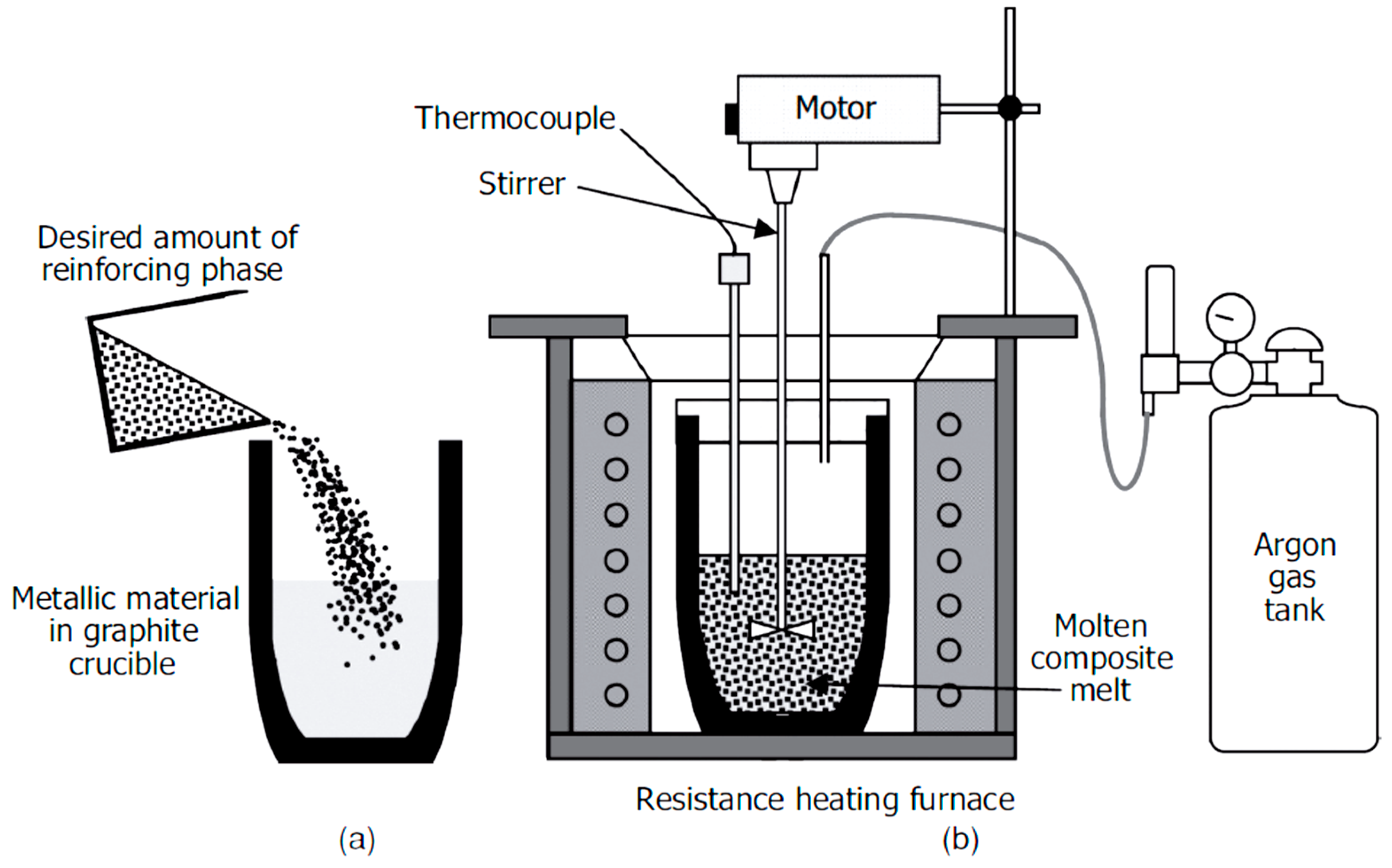
Figure 1. Typical stir-casting experimental setup [29].
Metals 09 00330 g001
Figure 2. Experimental setup for ultrasonic processing of nanocomposites with UST done (a) outside, and (b) inside the furnace [32].
Metals 09 00330 g002
Figure 3. Engineering stress and engineering strain curves of (a) AZ31 alloy and AC-UST specimens, and (b) AZ31 alloy and Iso-UST specimens [32].
Metals 09 00330 g003
Figure 4. Schematic diagram of disintegrated melt deposition setup [7].
Metals 09 00330 g004
Figure 5. Comparison of mechanical properties between liquid cast AC43A alloy, liquid cast AC43A/0.5 wt% SiC nanocomposite, and semi-solid cast AC43A/0.5 wt% SiC nanocomposites (30% solid fraction); (a) ductility comparison and (b) strength comparison [41].
Metals 09 00330 g005
Figure 6. Schematic representation of the fabrication of Al–Si3N4 nanocomposites [47].
Metals 09 00330 g006
Figure 7. Representative tensile stress–strain curves (a) and variation in YS, UTS, and elongation with an amount of Si3N4 (b) of extruded Al–Si3N4 nanocomposites [47].
Metals 09 00330 g007
Figure 8. The PM path followed by Pham et al. [48].
Metals 09 00330 g008
Figure 9. Dependence of the Brinell Hardness (HB) of the Cu/CNT nanocomposite on the mass fraction of the CNTs [48].
Metals 09 00330 g009
Figure 10. Schematic of the ball milling process (a). The used balls are hitting the CNTs and the matrix powder material (b), welding and integrating the two components (c), and the bounce of the powder particle to restart this process again at another spot (d) [53].
Metals 09 00330 g010
Figure 11. Schematic of composite manufacturing [66].
Metals 09 00330 g011
Figure 12. Schematic of the accumulative roll bonding (ARB) [81].
Metals 09 00330 g012
Figure 13. 3D representation of tensile strength (a) and elongation (b) versus the volume fraction and the number of cycles [81].
Metals 09 00330 g013
Figure 14. Number of publications on metal matrix nanocomposites in Web of Science.
Metals 09 00330 g014
Figure 15. Main mechanisms of ultrasonic deagglomeration of nanoparticle clusters: (a) collapse of cavitation bubble; and (b) acoustic streaming.
Metals 09 00330 g015
Figure 16. In situ ultrasonic processing setup on the Diamond–Manchester imaging branchline (I13-2) of the Diamond Light Source, UK. Schematic diagram on the right-hand side shows the furnace, crucible, and the sonotrode (inset is the view along the X-ray beam) [114,118,120].
Metals 09 00330 g016
Figure 17. Microstructure of (a) AM60; and (b) AM60 + AlN [127]. Microstructure is significantly refined using the addition of AlN nanoparticle as well as by irradiating the melt by an ultrasonic transducer.
Metals 09 00330 g017
Figure 18. Crystallography of an AlN particle within a magnesium matrix [127].
Metals 09 00330 g018
Figure 19. Importance of ultrasonic treatment to reduce the size of Si particle in Al-17%Si alloy [105].
Metals 09 00330 g019
Figure 20. Tensile properties of AZ91-SiC nanocomposites fabricated by ultrasonic-assisted casting followed by extrusion at different temperature [157].
Metals 09 00330 g020
Figure 21. Comparison of (a) tensile strength and (b) hardness of AA6061/Al2O3 composite fabricated by ultrasonic-assisted squeeze casting and ultrasonic-assisted stir casting processes [160].
Metals 09 00330 g021
Figure 22. Minimum creep rate vs. applied stress for Mg alloy (Elektron21) and Mg alloy-AlN composite at 240 °C [128].
Metals 09 00330 g022
Figure 23. Tribological properties of Al-B4C composite fabricated by ultrasonic-assisted casting: (a) wear rate, and (b) coefficient of friction variation [187].
Metals 09 00330 g023
Figure 24. Wight loss of tool steel pin with sliding distance for Al and Al2O3/Al composite [56].
Metals 09 00330 g024
Figure 25. Comparison of wear loss of Al-Al2O3/SiC composites produced by the casting route or powder metallurgy. Wear loss of PM samples is higher than those samples fabricated by casting regardless of the type of reinforcing agent (Al2O3 or SiC) [191].
Metals 09 00330 g025
Table 1. Properties of common particles used as nanoparticles for metals reinforcement [85,86].
TypeSiCAlNAl2O3B4CTiB2TiC
Crystal structureα: hdphdpα: hdprhombhdpcub
Lattice parameters [nm]a: 0.307
c: 1.008
a: 0.311
c: 0.498
a: 0.476
c: 1.299
a: 0.559
c: 1.205
a: 0.303
c: 0.322
a: 0.432
Melting T [°C]230030002045245029003140
Young’s modulus [GPa]480350410450370320
Density [g/cm3]3.223.263.982.534.494.92
Mohs hardness9.6-6.59.5--
CTE [10−6 K−1]4.96.08.35.47.47.4
supplier of nanoparticlesIoLiTec Nanomaterials, Skyspring Nanomaterials, Inc., Auer-Remy GmbH, ChemPur Feinchemikalien und Forschungsbedarf GmbH, Alpha Aesar
Table 2. Commercially available nanoparticles.
BaseCarbideNitrideBorideOxide
Aluminium AlN Al2O3
Antimony Sb2O3
BoronB4CBN B2O3
Bismuth Bi2O3
Cerium CeO2
ChromiumCrCCrNCrBCrO3, Cr2O3
Cobalt CoO, Co2O3, Co3O4
Copper CuO
Dysprosium Dy2O3
Erbium Er2O3
Europium Eu2O3
Gadolinium Gd2O3
HafniumHfCHfN HfO2
Indium In2O3
Iron Fe3O4, Fe2O3
Lanthanum LaB6La2O3
Magnesium MgO
Manganese MnO2, MnO3, Mn2O3
MolybdenumMoC, Mo2CMoN, Mo2NMoB, Mo2BMoO3
Neodymium Nd2O3
Nickel NiO, Ni2O3
Niobium Nb2O5
Praseodymium Pr6O11
Samarium Sm2O3
SiliconSiCSi3N4 SiO2
TantalumTaCTaN Ta2O5
Terbium Tb4O7
Tin SnO2
TitaniumTiCTiNTiB2TiO2
TungstenWC, W2CWN, W2NWB, W2BWO3
Vanadium VO, V2O3, V2O5
Yttrium Y2O3
Ytterbium Yb2O3
Zinc ZnO
ZirconiumZrCZrNZrB2ZrO2
Table 3. CTE and mechanical properties of Mg and its nanocomposites reinforced with CNTs [93].
MaterialCTE
[10−6 K−1]
0.2 Yield Strength
[MPa]
UTS
[MPa]
Elongation
[%]
Mg28.57127 ± 5205 ± 49 ± 2
Mg-0.06 CNT27.17133 ± 2203 ± 112 ± 1
Mg-0.18 CNT26.19138 ± 4206 ± 711 ± 1
Mg-0.30 CNT25.90146 ± 5210 ± 68 ± 1
Table 4. Grain size, hardness, density, porosity proportion, and mechanical properties of AM60 reinforced by AlN reinforcing agent with ~1500% reduction in grain size and 200% improvement in yield strength [127].
PropertyAM60AM60 + AlN
Grain size [µm]1277.0 ± 301.384.9 ± 6.2
Hardness [HV5]48.0 ± 4.046.4 ± 6.0
Density [g/cm3]1.7848 ± 0.00041.783 ± 0
Porosity [%]-0.919
Yield strength [MPa]44.9 ± 6.991.2 ± 3.8
UTS [MPa]109.3 ± 19.2235.1 ± 6.4
Elongation [%]6.4 ± 3.415.4 ± 4.2
Table 5. Percentage improvement in mechanical properties of MMNCs fabricated by ultrasonic treatment during casting.
Matrixwt%% ImprovementReference
A356SiC = 1.5 wt%UTS = 100%[117]
Mg-2Al-1SiSiC = 2 wt%UTS = 15%[129]
2024 Al alloyAl2O3 = 1 wt%YS = 45%[126]
Mg-6ZnSiC = 1.5 wt%UTS = 55%[162]
Al7075Al2O3 = 1.5 wt%UTS = 59.6%[163]
Al7075SiC = 1 vol%YS = 12%[164]
A356Al2O3 = 1 wt%UTS = 15%[165]
A356SiC = 1 wt%UTS = 24%[165]
Al-4.4CuTiB2 = 2 wt%YS = 65%[166]
AA6061 SiC = 1 wt%UTS = 3%, Elongation = 100%[167]
AA6061Al2O3 = 1 wt%UTS = 6%, Elongation = 100%[167]
AA2219SiC = 2 wt%UTS = 36.5%[168]
Table 6. Mechanical and tribological properties of MMNCs produced by the powder metallurgy route.
MatrixReinforcement-Content% Improvement in Mechanical/Tribological Properties with Respect to Matrix MaterialReference
AluminumGr = 1.5 wt%TS = 63%[173]
Al6061Gr = 1 wt%Flexure strength = 15%[174]
AluminumGr = 0.5 wt%TS = 16%[175]
AA6061Gr = 10 vol%E = −35%, Hardness (H) = −13%, COF = −72%.[176]
AA2124Gr = 3 wt%Wear rate = −47%[174]
CopperGr = 1 wt%TS = 12%[177]
TiGr = 5 wt%H = 200%[172]
AluminumCNT = 5 wt%TS = 100%[178]
Aluminum CNT~1 wt%TS increased four times and no change in elongation[179]
AluminumCNT = 5 wt%Hardness = 28%, COF = −100% [180]
AluminumCNT = 0.4 wt%TS = 30%, Elongation reduced from 35 to 1%.[171]
CopperCNT = 16 vol%H = 94%, COF = −100%[181]
NiCNT = 10 vol%COF = −100%[182]
AluminumSiC = 10 wt%Compressive strength = 71%[183]
Negative sign indicates reduction in properties.