Article

Tribochemical Behavior of Pure Magnesium During Sliding Friction

1
School of Mechanical and Electric Engineering, Guangzhou University, Guangzhou 510006, China
2
Guangdong Insititue of New Materials, National Engineering Laboratory for Modern Materials Surface Engineering Technology, The Key Lab of Guangdong for Modern Surface Engineering Technology, Guangzhou 510651, China
3
Tribology Research Institute, State Key Laboratory of Traction Power, Southwest Jiaotong University, Chengdu 610031, China
4
Key Laboratory of Advanced Technologies of Materials, Ministry of Education, Southwest Jiaotong University, Chengdu 610031, China
*
Authors to whom correspondence should be addressed.
Metals 2019, 9(3), 311; https://doi.org/10.3390/met9030311
Submission received: 24 January 2019 / Revised: 1 March 2019 / Accepted: 4 March 2019 / Published: 9 March 2019

Abstract

:
Reciprocating sliding friction tests were conducted on pure magnesium using a UMT-II tester. The tribo-chemical behavior was characterized using X-ray photoelectron spectroscopy (XPS) and electron probe micro-analyzer (EPMA), which showed that the tribo-chemical behavior of pure magnesium was due to a tribo-oxidation reaction. At room temperature, the debris layer on the worn surface contained Mg(OH)2, MgO, and MgCO3. According to the reciprocating sliding friction mechanism, the decomposition of MgCO3 into MgO should occur. XPS results revealed that the surface oxide layer, containing Mg(OH)2, and MgO, acted as a third layer to protect the surface. Apparently, Mg(OH)2·nH2O was the main tribo-chemical product of pure magnesium under sliding friction.

1. Introduction

In 1966, Jost defined the term “tribology” to demonstrate how friction and wear have a significant impact on the British economy [1]. Although, the tribological properties of steels has been investigated by many researchers, tribological characterization of nonferrous metals, especially for magnesium and its alloy, is not wildly studied [2]. Owing to unique properties such as low density and high specific strength, magnesium and its alloys have attracted much attention in automotive and aerospace industries [3]. However, their poor corrosion and wear resistance imposes certain limitations for their widespread application. Many studies have focused on the corrosion properties of magnesium [4,5], however, the tribological behavior of pure magnesium is not well understood. Improving the wear resistance of magnesium can achieve low friction and long life of friction parts [6]. Magnesium usually forms a protective oxide film under ambient condition. Yingwei et al. [7,8] investigated the formation of oxide films on Mg-Li alloys, which showed a multilayer structure, consisting of Li, Mg, and O. Mg also reacts with H2O, which may result in Mg(OH)2 formation and hydrogen evolution according to Mg + 2H2O → Mg(OH)2 + H2 [9].
The corrosion of magnesium has been shown to depend on the oxygen concentration [10], however, it has been suggested that magnesium corrosion is relatively insensitive to oxygen concentration differences. Ghali [11] proposed that the corrosion of Mg and its alloys could be initiated by the hydrolysis reaction, in which case, the oxygen concentration does not play a major role in the corrosion mechanism. Therefore, there is still controversy regarding the effects of oxygen on magnesium corrosion, which is related to the surface chemical states [12]. The tribochemical behavior during sliding friction is similar to the process of corrosion. The rubbing surface is the key to understanding the tribo-chemical behavior and how wear of magnesium is induced. Nguyen et al. [13] performed dry sliding wear tests on AZ31B Mg alloy.
The aim of this study was to elucidate the interaction between the air atmosphere and magnesium surface during reciprocating sliding friction tests. In order to understand the oxidative wear behavior before and after reciprocating sliding friction, the chemical composition of the oxide layer and morphologies of worn scars were characterized. Different normal loads were used to remove the surface oxide layer of pure magnesium formed in the air. The oxide layers on the magnesium alloy were investigated, in detail, in order to study the effect of the third body on the friction process. The findings of this study are expected to contribute to the development of Mg-based components for high-perfomance application with improved wear resistance.

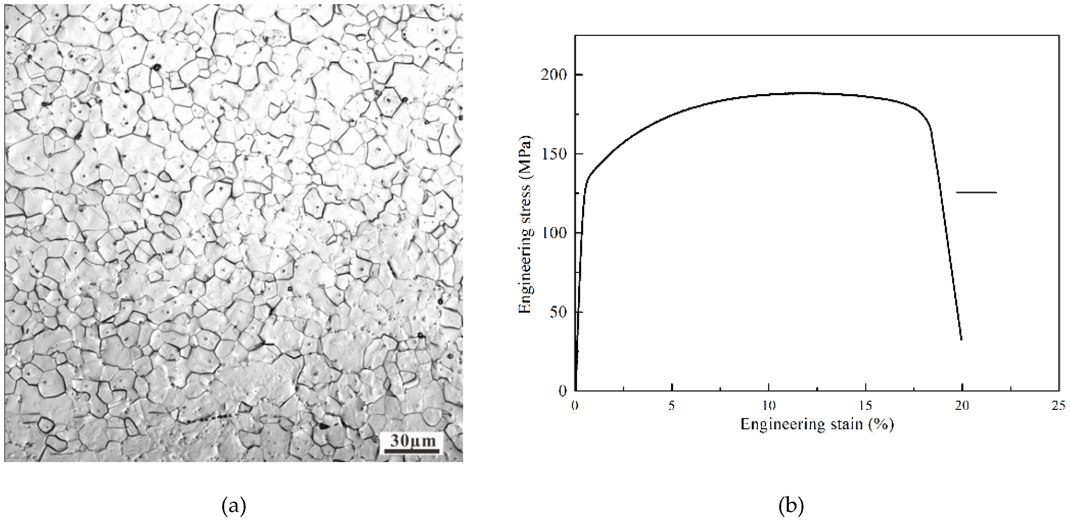
2. Material and Methods

A 99.9% pure Mg sample was used in this study and was machined to a size of 30 mm × 30 mm × 2 mm. As shown in Figure 1, the grain size of the pure magnesium was less than 100 μm and the strength stress of the pure magnesium was 180 MPa. The friction tests were carried out at room temperature in ambient air using a UMT II tester (CETR, USA) at various loads with a reciprocating sliding friction frequency of 1 Hz, displacement of 4 mm, and test duration of 1 h. Normal loads of 0.1, 1, 10, and 100 N were applied to achieve initial Hertzian contact stresses of 130, 300, 640, and 1400 MPa. No additional lubricant was added during testing. Each test was repeated at least three times. The friction pair for the test consists of a WC-ball of diameter 10 mm with 17 GPa hardness, and flat specimens of the 99.9% pure Mg. Before testing, the flat samples were ground and then polished by using 0.25 μm Al2O3 with a surface roughness of 0.064 μm. The worn surface morphologies of the flat samples were inspected using the optical microscopy (BX41, Olympus, Tokyo, Japan) and imaged using a scanning electron microscope (SEM; XL-30ESEM FEG, FEI, Hillsboro, OR, USA). The elemental compositions of the composite surfaces and tribo-films generated on the steel surfaces were analyzed using electron probe micro-analysis (EPMA; JAX-8230, JEOL, Tokyo, Japan) with an operating voltage of 20 kV. After the reciprocating sliding friction tests, the wear volume of the samples was evaluated using three-dimensional optical surface profilometry (3D Nano-map, Bruker, Karlsruhe, Germany). Fourier transform infra-red spectroscopy (FT-IR) was carried out using a Thermo Nicolet 380 spectrometer (Thermo Fisher Scientific, Waltham, MA, USA). The interaction between Mg2+ and C=O was characterized using a resolution of 4 cm−1, frequency range of 4000–400 cm−1, and operating temperature of 23–25 °C. X-ray photoelectron spectroscopy (250Xi, Thermo Fisher, Waltham, MA, USA) was carried out using Al Kα X-ray radiation (1486.6 eV). The spectra were obtained using a pass energy of 20 eV, and the pressure in the chamber was maintained at ≤10−7 Pa during data collection. The C 1s neutral carbon peak at 284.8 eV was used as the reference for analyzing all binding energies. The Mg 2p spectrum was further resolved into its component peaks using XPS Peak software (version 5.59, Thermo Fisher Scientific, Waltham, MA, USA).

3. Results and Discussion
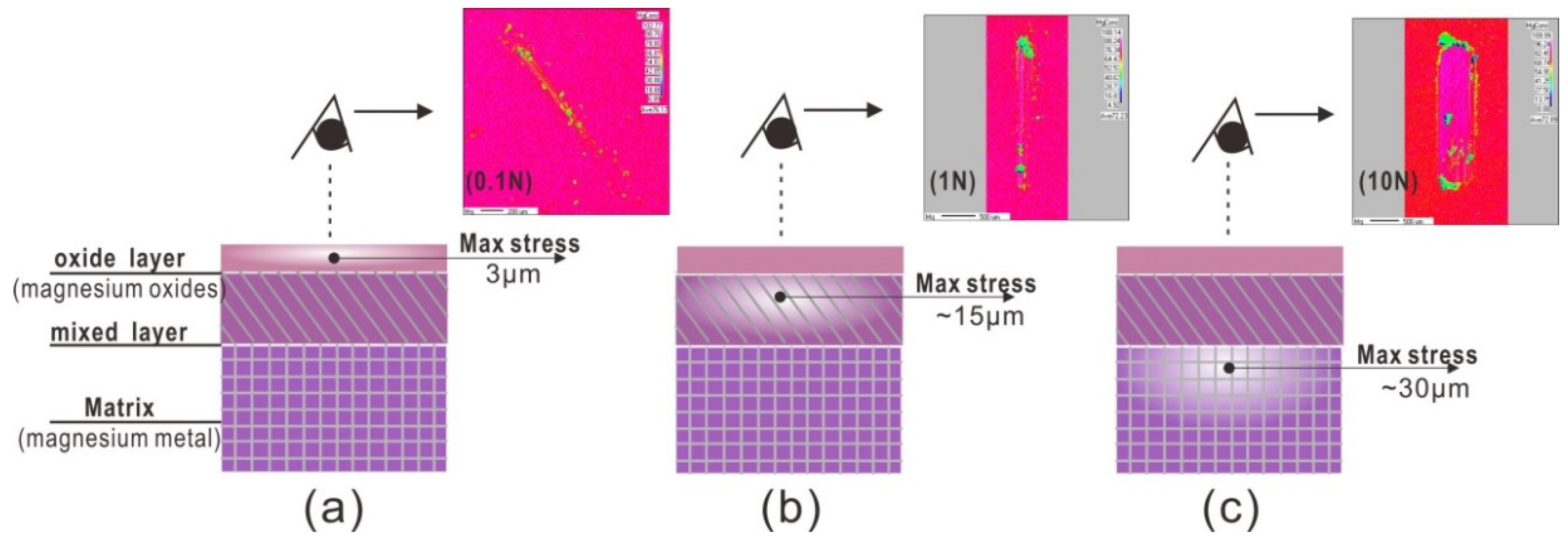
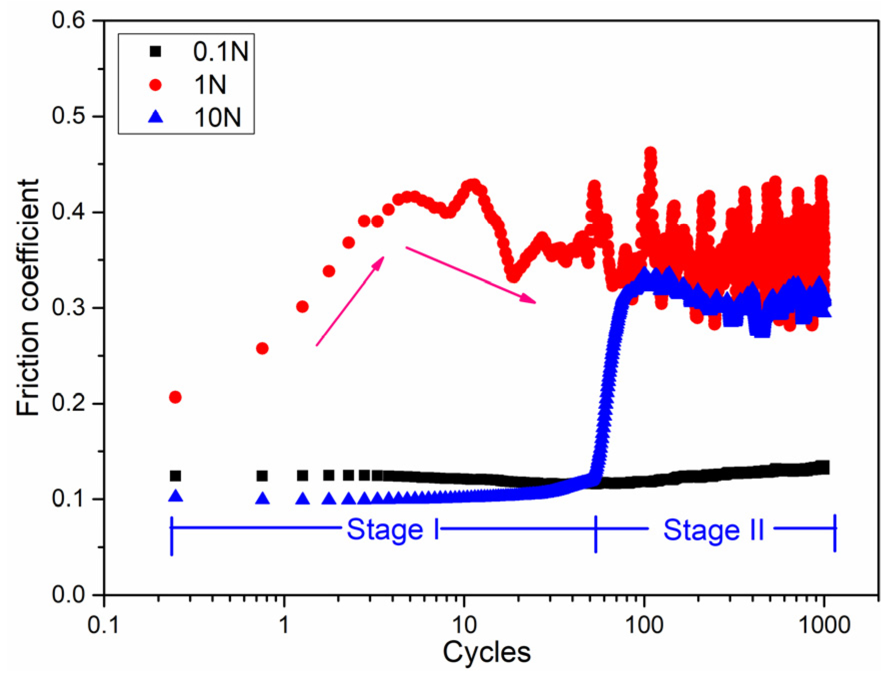
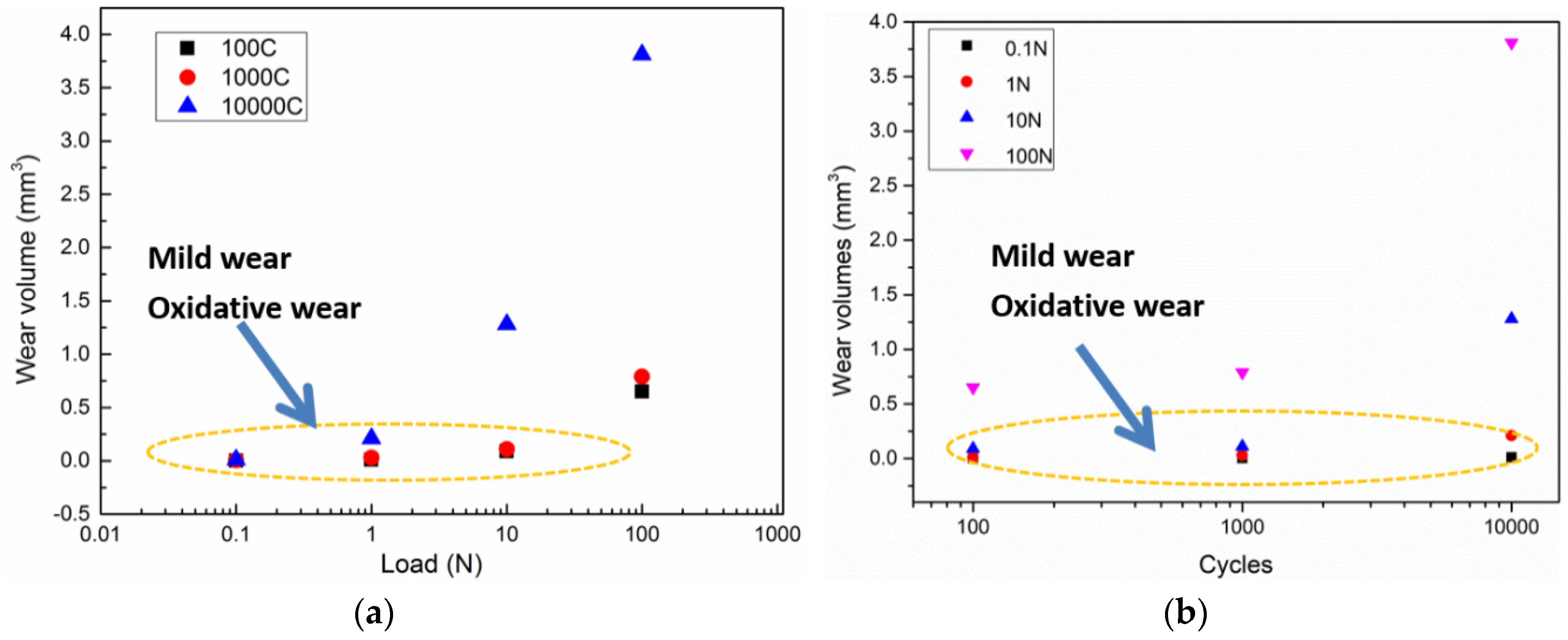
3.1. Wear Behavior

To scratch the surface oxide layer using the sliding friction method, the friction coefficient obtained at different loads is shown in Figure 2. The different trends in the friction curves indicate that the state of friction contact interface changed. The friction coefficient showed initial values of 0.1, 0.2, and 0.1, corresponding to loads of 0.1, 1, and 10 N, respectively, hence, a maximum initial friction coefficient was observed for a load of 1 N. The friction curve showed a low stable value of 0.1 over the whole cycles. At a load of 1 N, the friction curve showed two distinct stages. In the first stage, the friction curve increased rapidly from 0.2 to 0.4 over the first 10 cycles. In the second stage, the curve showed oscillating behavior after the 100 cycles. For a higher load of 10 N, the two stages were different: for the first 100 cycles, the friction curve was similar to that at 0.1 N, while after the 100 cycles, the friction curve was similar to that at 1 N with a smaller amplitude of oscillation. Therefore, the run-in period varied under different normal loads, and was about 100 cycles at loads of 0.1 and 10 N, and about 10 cycles for load of 1 N. For load conditions of 1 and 10 N, the surface oxide layer was scratched and fractured, with a new fresh Mg metal surface exposed to the air environment after about 100 cycles, which was also demonstrated by the EPMA mapping images discussed in the following section.
Figure 3 shows the changes in the wear volume (mm3) with increasing load. The wear volume of the wear scars on magnesium samples were inspected using a 3D nano-map after the reciprocating sliding friction. Figure 3a shows that, for loads below 10 N, the wear volume ranged from 0 to 1.5 mm3 as the wear cycles increased from 0 to 104 cycles. The maximum wear volume of around 4 mm3 was observed at a load of 100 N after 104 cycles. The data indicated by the oval area in Figure 3 correspond to slight wear damage as the wear volumes were close to zero. Considering the effect of load on the wear behavior of pure magnesium, the increasing trend of wear volume with increasing load was not highly significant, showing a similar wear volume of 0.02 mm3 for all loads below 10 N. This corresponds to the mild wear zone from wear mapping [14]. In addition, the wear volume curves as function of increasing load for 102, 103, and 104 cycles, were similar. High loads had a larger effect on the wear volume than long cycles. Hence, load had the main effect on the wear behavior and wear mechanism during reciprocating sliding friction tests. Severe wear is usually accompanied by removal of a large amount of material, where the surface state changes too fast to distinguish the tribochemical and tribo-mechanical behavior. In order to investigate the tribochemical behavior, the severe wear damage over long cycles to needs be avoided [15]. Therefore, friction tests at low load of 0.1 and 1 N were used to characterize the tribochemical behavior.

3.2. Tribochemical Behavior

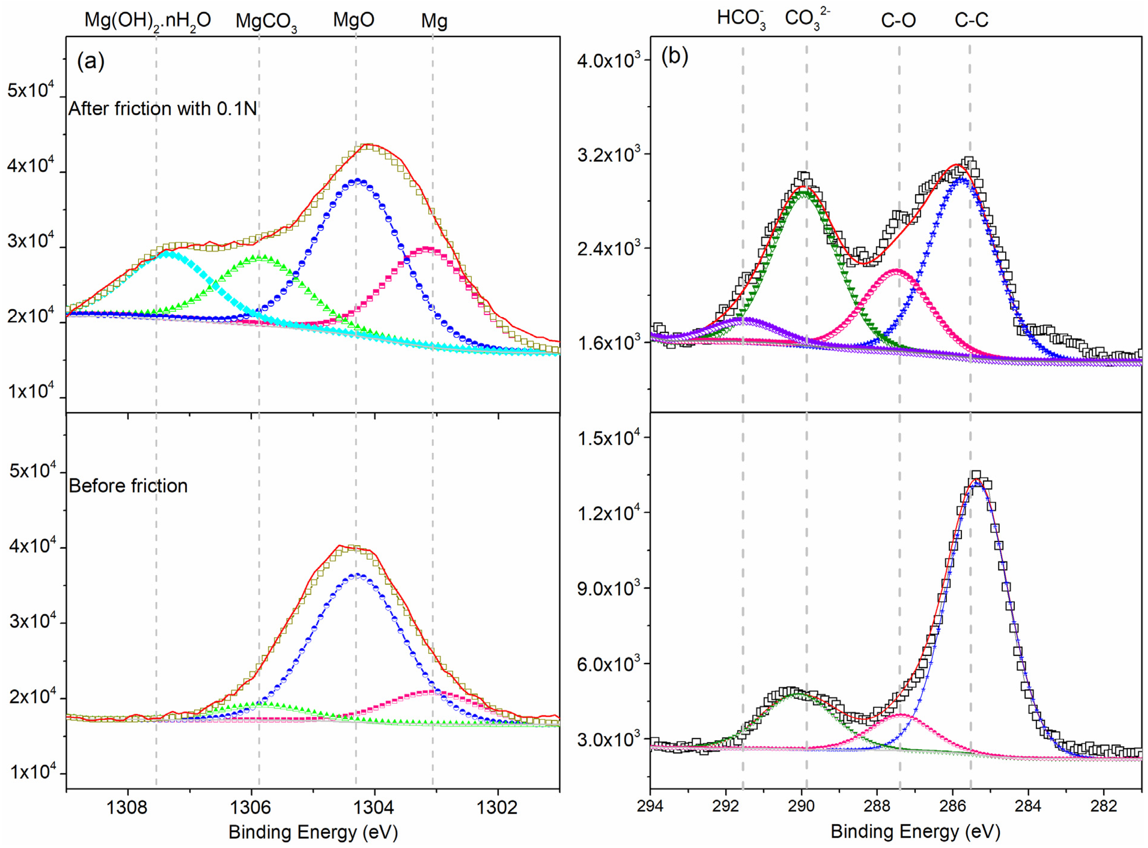
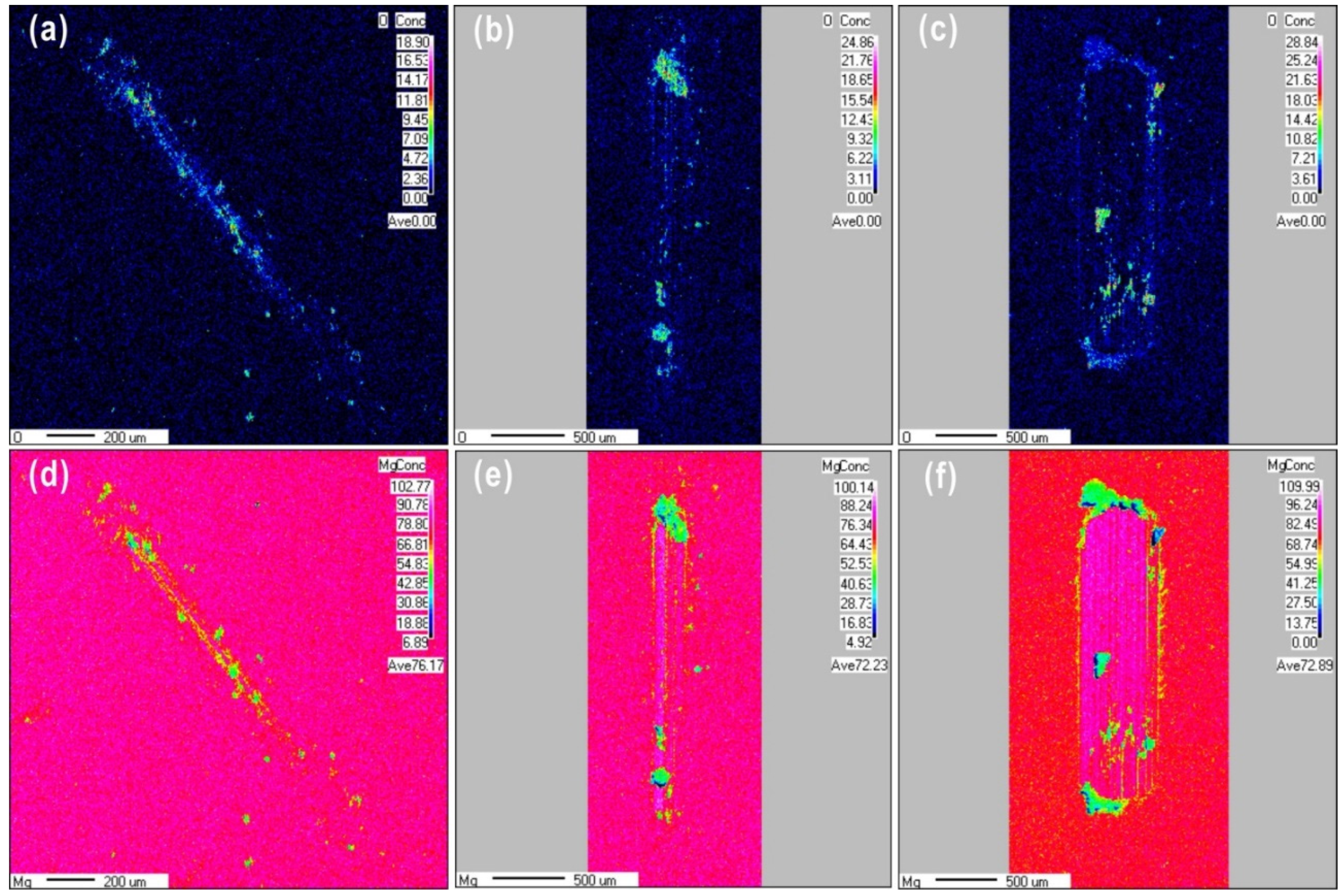
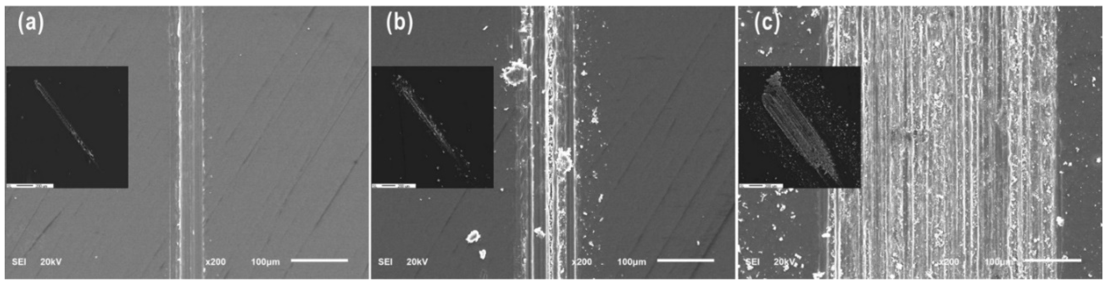
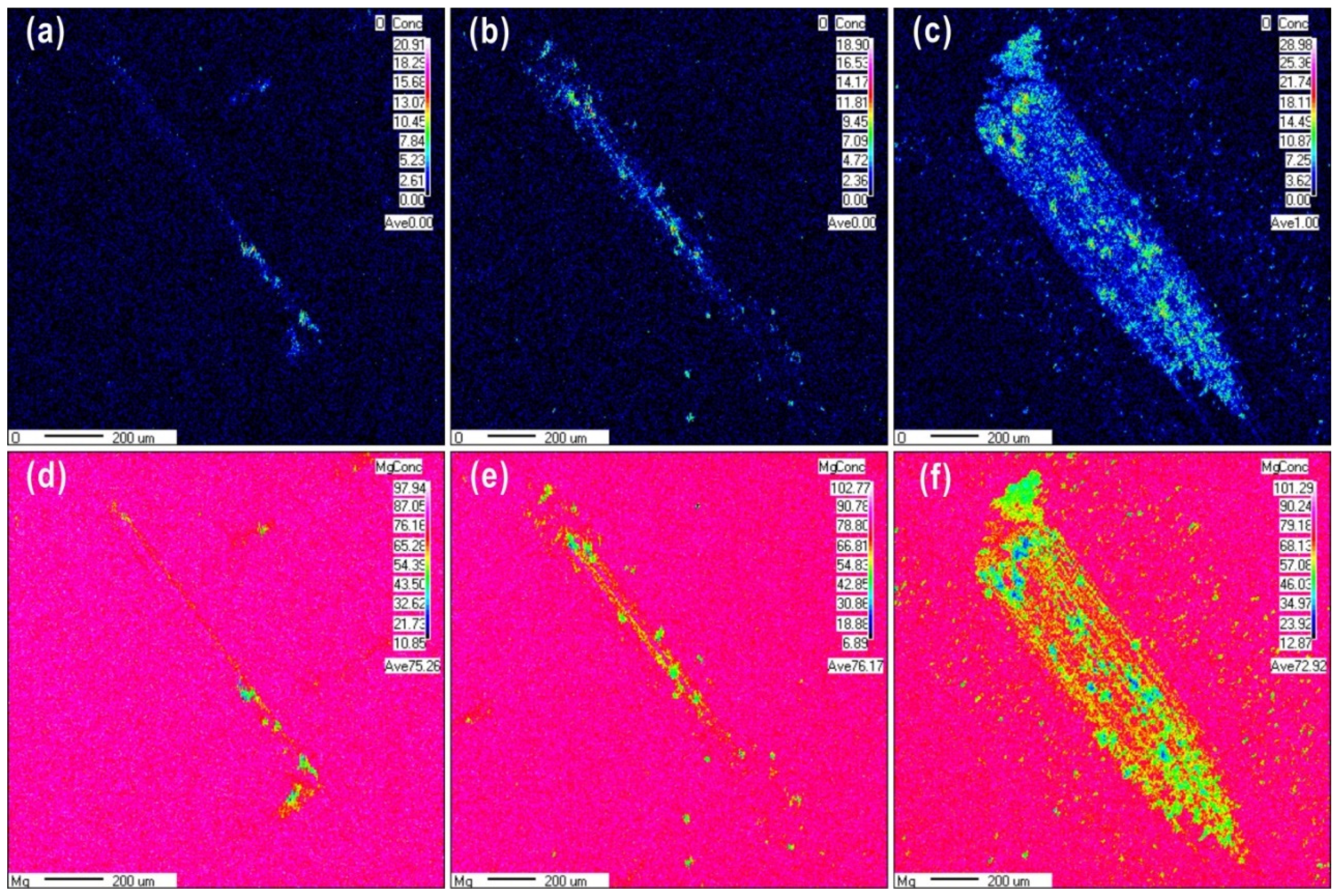
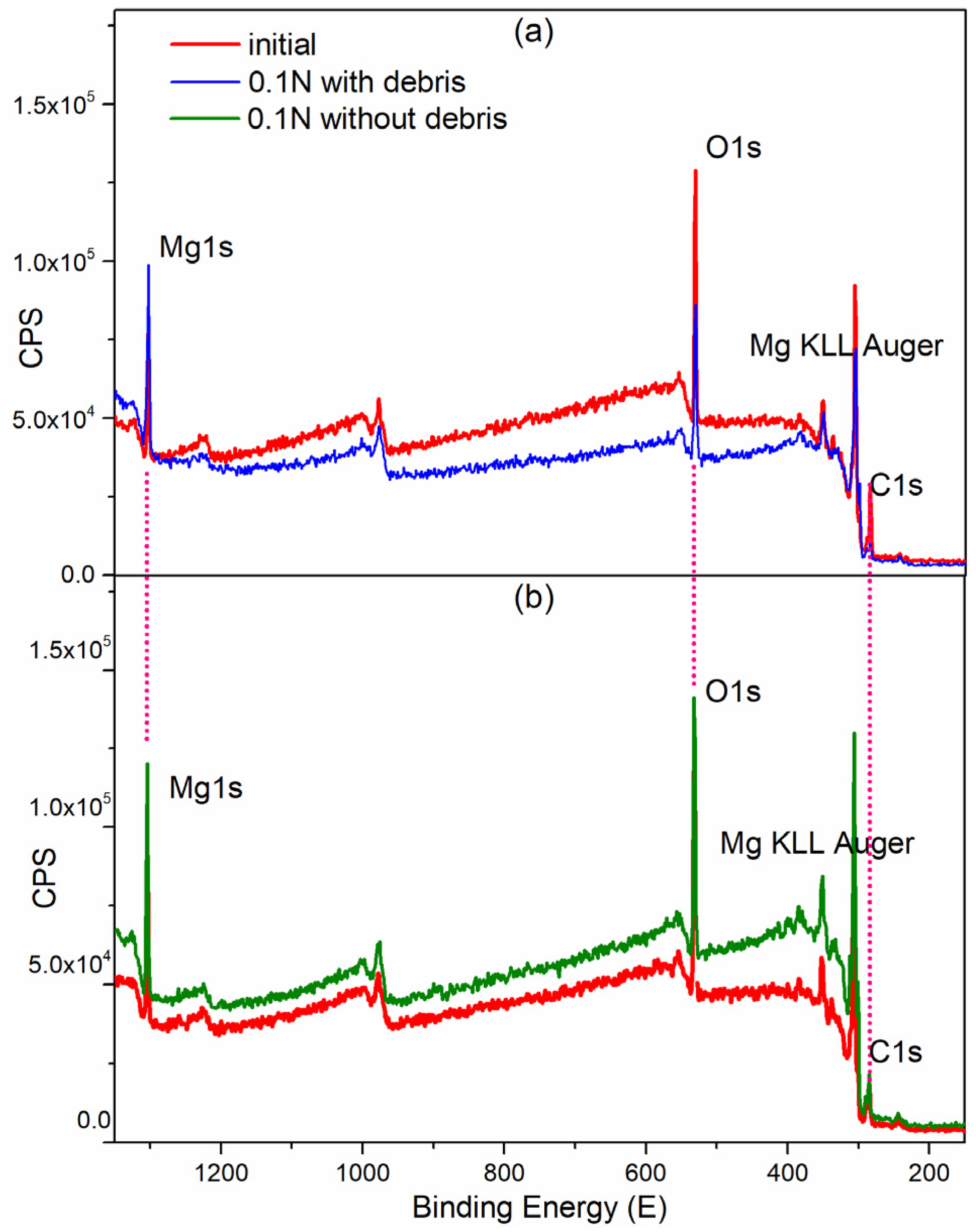
3.2.1. Surface Chemical Composition

The surface chemical composition of the worn surface was observed using EPMA mapping, as shown in Figure 4 for wear scars produced under different loads after 100 cycles. Obviously, the size of the oxide particles formed during sliding friction increased as the normal load increased. It can be clearly seen that an oxide layer is covered the wear scars at the load of 0.1 N. At a higher load of 10 N, wear debris was observed surrounding the wear scars. This debris had high oxygen content covered on the worn scars with the high content oxygen. The oxygen content of the worn surface increased from 18.9% to 28.8% as the load increased from 0.1 to 10 N, respectively, while the magnesium content decreased from 76.17% to 72.8%, respectively. At loads of 1 and 10 N, the Mg content in the contact zone was higher than that in the zone without wear. The distribution of Mg over the wear scar produced at a load of 0.1 N was almost uniform. The load of 0.1 N may have been insufficient to remove the oxide film, or the tribochemical behavior could have been activated to form a tribofilm covering the friction contact areas. In the case of a load of 1 N, sliding friction partially removed the film, exposing some fresh metal surface. At a load of 10 N, the oxygen content of the wear scars decreased due to a higher amount of fresh magnesium metal being exposed; the oxide film was completely removed by friction, or the rate of oxide layer formation was much lower than that of the layer being removed. Therefore, during reciprocating sliding friction, exposure of fresh metal surface may require a normal load above 1 N. In addition, it is clear shown that the different structures at different depths from Mg mapping images, after 100 friction cycles, the content of fresh Mg metal has increased gradually from the top worn surface to the matrix.
Therefore, to investigate the tribochemical and oxidation behavior, the reciprocating sliding friction condition at a load of 0.1 N was considered. Figure 5 shows wear debris for a range of cycles at a load of 0.1 N. Debris flakes were formed at 100 cycles, and then continuously formed fine particles at contact interfaces as cycles increased. With further wear cycles, the contact width of wear zone increased, corresponding to an increasing amount of wear particles.
Figure 6 shows EPMA mapping images of wear scars formed at 0.1 N over a range of wear cycles. The wear scars become larger and the oxygen content increased from 20% to 28.98% as the cycles increased from 10 to 1000 cycles. The distribution of oxide particles on the contact surface extended from a localized region to the entire wear scar area as the cycle number increased. Oxidative wear is the main wear mechanism at the low load, and distribution of oxygen element on the worn scar surface is uniform due to the fine powder debris. The wear scars were covered by a layer of the oxidative debris, which accumulated continuously with further cycles.
Coefficient friction was effect by the state of contact interface during sliding friction tests. Generally, two main factors were considered; firstly, according to classical theory of contact mechanics [16], the mechanical model for the sliding contact friction pair is a contact mechanical problem. Distributions of the max stresses for a load of 0.1, 1 and 10 N, are different. The max contact stress is 130, 300, and 640 MPa, and the depth of the max stress is 0.006, 0.014, and 0.03 mm. Secondly, from EPMA results at 100 cycles, the load of 0.1 N can only remove the oxide layer, as the load increased to 1 N, the oxide layer and partial fresh metal Mg can be observed. However, the load at 10 N, Metal Mg matrix was directly removed without the oxide tribofilm on sliding zone.
For the load of 0.1 N, the tribo-oxidation is main reaction at contact interface, and contact stress has not been changed, hence, the friction coefficient is low and stable. For the load of 1 N, the abrasive wear occurred. A large amount of debris mixed with fresh metal particles and oxide particles, was formed at contact interface. Hence, the state of contact interface always changed due to wear particles behavior. After 100 cycles, contact interface condition can kept at a balance state. Hence, friction coefficient curve, which is gradually increasing to the constant level, can be divided into two stages. For the load of 10 N, at the first 100 cycles, the Mg material went through a deformation process from elastic to plastic without the debris behavior, and then resulted in the fatigue with micro-cracks in matrix with the fresh metal surface exposed. Hence, friction coefficient curve separated into two different stages. As the friction occurred under the different loads, the wear mechanism transfers oxide to abrasive wear, it shows in Figure 7.

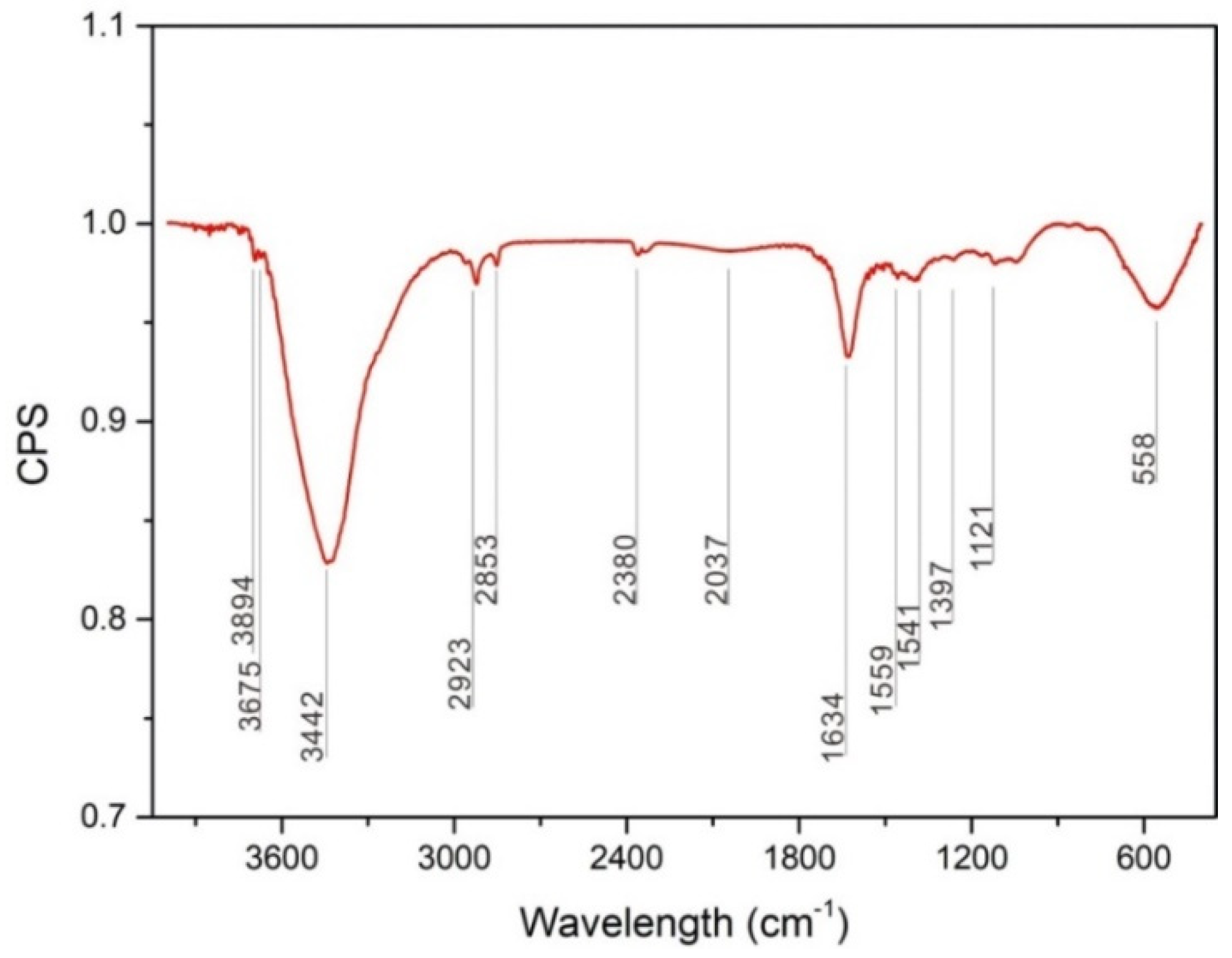
3.2.2. FT-IR spectra
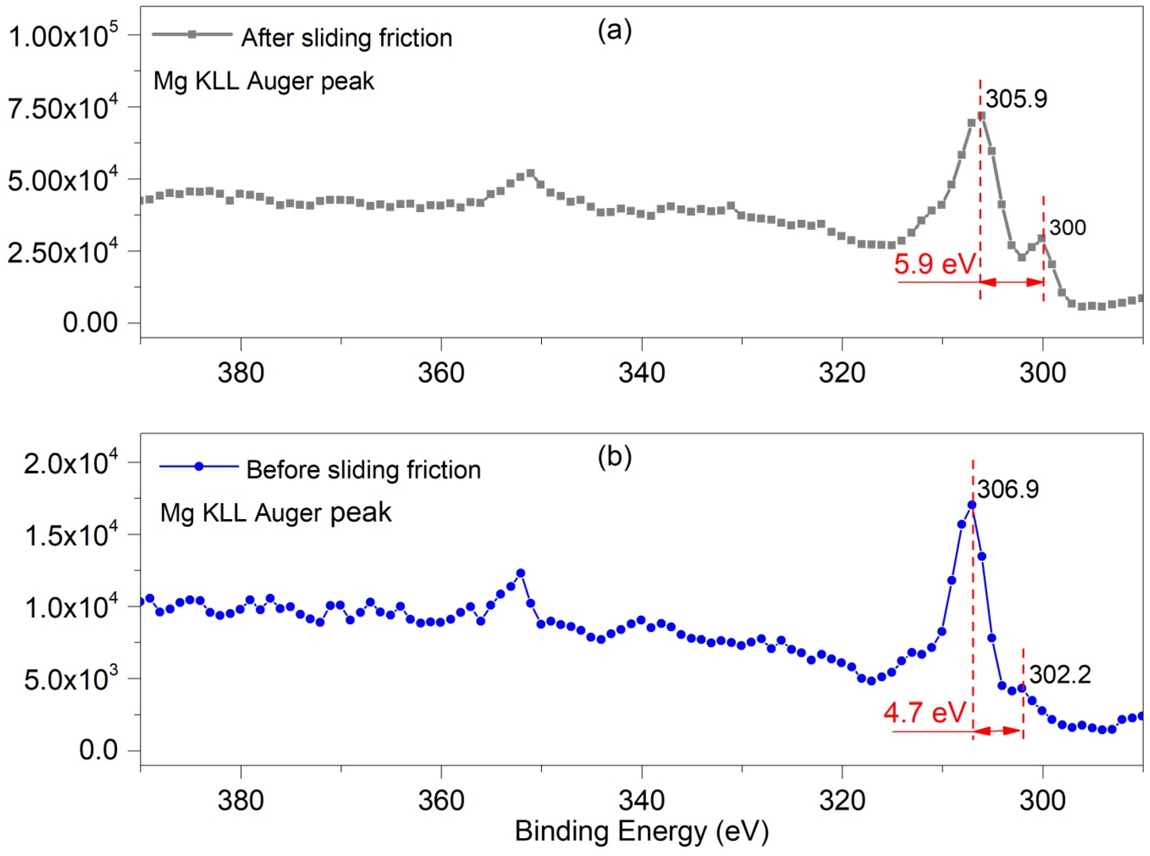
In this study, we observed that the tribochemical reaction during reciprocating sliding friction process was oxidative wear behavior, which occurred at low loads of 0.1 and 1 N. A cyclic wear process occurred involving the formation of an oxide layer via a tribochemical reaction, which was then broken and removed during sliding; this exposes a fresh metal surface, which was again oxidized by the tribochemical reaction. Oxide debris was collected to investigate the tribo-oxidation behavior during sliding friction and the composition of the tribochemical layer was analyzed using FT-IR. Figure 8 shows the FT-IR spectrum of wear oxide debris collected after 1000 cycles at a load of 1 N, which shows strong peaks at 3442, 1634, 558 cm−1. Specifically, the OH showed the strongest absorption bands at 3442 cm−1, 1634 cm−1 in Mg(OH)2 [17], bands of CO32− in MgCO3 were observed at 1559 cm−1, 1541 cm−1 [18], while the absorption bands of O2− in MgO was at 558 cm−1 [19]. Therefore, the oxide layer or the tribochemical product was expected to be MgCO3, Mg(OH)2, MgO.

3.2.3. XPS

To understand the tribochemical reaction at the contact interface during sliding friction, the surface chemical state of the top 2–3 layers atoms on the worn surface were analyzed using XPS. Table 1 and Figure 9 show XPS data from the worn surface of the same sample before and after removing wear debris. The matrix surfaces were contaminated by free carbon from the air, hence, C 1s peak at 284.8 eV was used as a reference for all binding energies.
Figure 9 shows a lower XPS peak intensity for the worn surface covered with wear debris than that of surface, without wear debris, attributed to surface electron effects. However, regardless of the presence of wear debris, the XPS peaks of all main elements maintained their binding energy positions. For example, the Mg 1s peak at 1303.5 ± 0.5 eV, and the O 1s peak at 531.5 ± 0.5 eV [20]. Table 1 shows that, the full-width-at-half-maximum (FWHM) of the O 1s peak in the worn zone covered with wear debris was 3.88 eV, while it is 3.4 for the matrix without wear. This indicates that the wear products induced by friction were different oxide products formed naturally in air without friction. Generally, a broad FWHM indicates that the chemical states of the elements are complex.
Figure 10 shows the Mg KLL Auger spectrum which obtained from the matrix surface before and after sliding friction. The Mg 1s peak often shows Auger peaks at 300–390 eV [20,21], where the principal Mg KLL Auger peak (binding energy 300–306 eV) has a chemical shift [22]. Figure 10b shows data for, the initial Mg surface, where the main Auger peak of the native Mg oxide was around 306.9 eV [23] and the Auger KLL peak of the Mg metal was at 302.28 eV [23]; this deference between these two peaks is 4.7 eV. After 1000 cycles of sliding friction at 0.1 N normal load, the Auger KLL peak of Mg oxide shifted to 305.9 eV, while that of Mg metal changed to 300.05 eV; this deference between these two peaks increased to 5.9 eV after sliding. This indicated that the chemical states of the Mg oxides changed due to the friction. Therefore, the tribochemical behavior induced by the sliding friction made the number of different states increased the worn surface of pure magnesium.
With increasing test cycles or load, the decomposition of MgCO3 into MgO occurs. In the case of the magnesium compounds observed here, the theoretical ratio of O/Mg is 2.0 in Mg(OH)2, while that of O/Mg is 3.0 in MgCO3, and that of O/Mg is 1.0 in MgO. Table 2 shows the atomic percentage determined from the C 1s, Mg 1s, O 1s peaks before and after sliding friction tests. The surface compounds were thought to mainly consist of MgCO3, MgO, and Mg. The O/Mg ratio was 3.05, corresponding to an O/C ratio of 1.50 and Mg/C ratio of 0.49 in the matrix. This suggests that most compounds of the area without wear zone should be MgCO3, while the ratio of O/Mg was 2.23 in the worn surface with debris; the surface layer mainly consisted of Mg(OH)2, which was considered to be the main wear product induced by sliding friction. The ratio of O/Mg changed to 2.76 after the debris was removed, suggesting that the main component of the worn surface without debris was Mg(OH)2 with MgCO3. Assuming that the carbon contamination is constant, the ratio of O/C was the highest when the debris covered the worn surface, hence, the oxygen content decreased due to removal of the oxide debris. In addition, the Mg content simultaneously decreased, resulting in a decreased in Mg/C ratio from 1.61 to 0.59.
The high resolution XPS spectra are shown in Figure 11. In the case of the Mg 1s spectrum, the FWHM of the peak for elemental Mg at 1302.53 ± 0.5 eV [24] was 1.8 eV. We observed an oxide peak at 1303.5 ± 0.2 eV, metal carbonate peak at 1304.8 ± 0.1 eV [25], and Mg(OH)2·nH2O is 1306.5 eV. Details of this data are shown in Table 3. In addition, the high-resolution scan of the C 1s spectra showed, FHWM of the elemental C peak of 2.0 eV in the matrix, with a C–C peak at 284.8 eV, C–O peak at 285.5 ± 0.2 eV, carbonate peak at 286.8 ± 0.1 eV, hydrocarbonate peak at 291.6 eV. For sliding friction tests at a load of 0.1 N, the wear debris consisted of the Mg(OH)2·nH2O, MgCO3, MgO, and Mg. The tribo-chemical behavior is related to absorption of H2O on the worn surface in the air ambient which can result in the formation of Mg(OH)2·nH2O.
In an air environment without sliding friction, pure Mg naturally formed the MgO, MgCO3, and a small amount of metal Mg remaining at the surface. Under a sliding friction of 0.1 N, the tribochemical reaction resulted in the formation of a new product, Mg(OH)2·H2O with a content of 17%. As the sliding friction progressed and exposed fresh Mg metal, the Mg content increased from 14% to 25%, while the content of MgCO3 decreased from 22% to 17%. In addition, the surface was contaminated with carbon that allowed formation of MgCO3. When the fresh metal surface is exposed by friction, the metal oxide is formed simultaneously [15], resulting in subsequent formation of MgO formed during sliding friction. The oxide layer, consisting of Mg(OH)2·H2O, MgCO3 and MgO, had a solid lubricating effect and protected the worn surface. When the worn surface was covered by a tribolayer or third body bed, lubrication occurred at the contact interface, resulting in a very smooth friction curve in Figure 2.
At temperature of 800–900 °C [19], MgCO3 is generally decomposed to form MgO. Friction can reduce the decomposition temperature of MgCO3. When less organic carbon is attached to the surface, more MgO appears in the wear debris, which can react with the large amount of H2O atoms on the contact interfaces.
Before the tribology tests, the Mg surface was covered by an oxide film, where the MgO and MgCO3 content were 64% and 22%, respectively, the details were shown in Table 4. After wear due to sliding friction at 0.1 N, tribochemical reactions occurred and the surface composition changed, with some of Mg(OH)2·H2O forming, as shown in Figure 12. In this case, H2O atoms can be easily attached to the tribofilm on the worn surface [15]; some of the Mg(OH)2 was hydrated to form the Mg(OH)2·H2O. When Mg contacts with H2O, MgO formed firstly, and then changed to Mg(OH)2 spontaneously depositing on the metal surface.
In previous studies, when stable MgO coating is exposed to a corrosive solution, with increasing MgO content in the oxide coating layer, better corrosion protection performance is observed for the coated Mg alloy. The Mg(OH)2 content in the corrosion zone was higher than that in the passivation zone, while the corrosion zone had less MgO than that of the passivation zone [26]. Therefore, an oxide layer containing a high content of Mg(OH)2·H2O is highly advantageous for the tribochemical reaction during sliding friction.

4. Conclusions

We investigated the tribochemical behavior of pure magnesium using the ball on plate tribological model with a low contact stress during dry reciprocating sliding friction tests. The elemental distribution and chemical state of the worn surfaces were characterized using FT-IR, EPMA and XPS, and the results were compared to those of the original metal.
(1)
Under an air atmosphere, the typical tribochemical behavior was tribo-oxidation, which frequently observed in the region of mild wear corresponding to the oxidative wear mechanism. As the load increased, the wear mechanism transformed from oxidative to abrasive wear.
(2)
During tribo-oxidation, the tribofilm on the worn zone of the pure Mg acted as a third body layer and fine particle debris was observed. The tribofilm had shown a stable low friction coefficient. As the tribo-film was damaged with increasing load or number of cycles, the friction coefficient became unstable and increased steeply due to wear mechanism transition to abrasive wear.
(3)
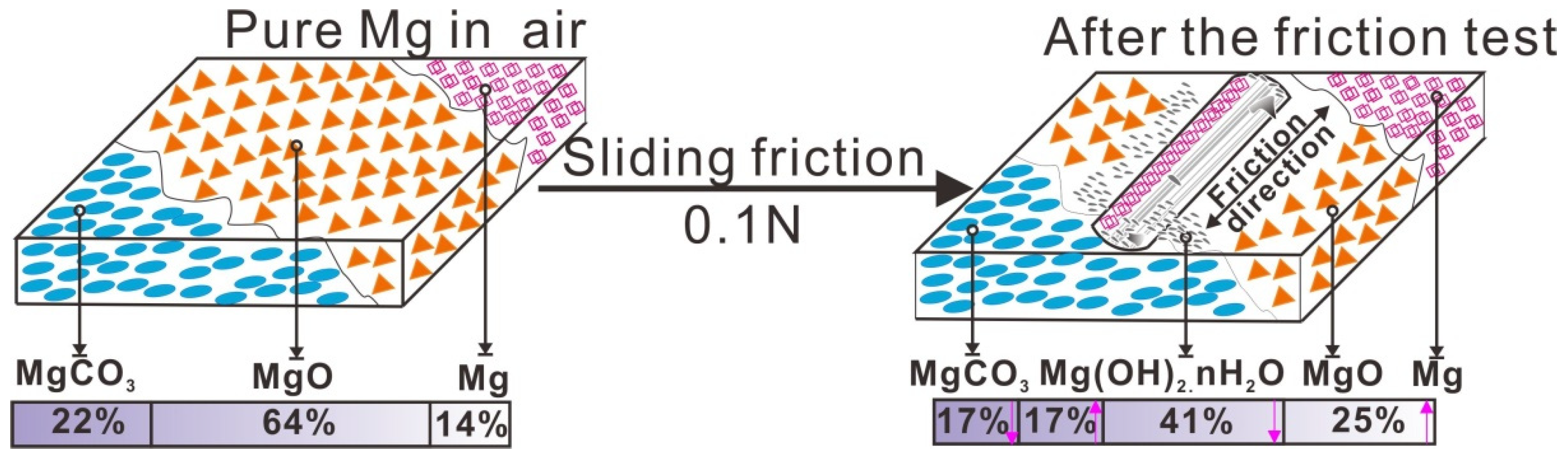
The third body layer formed at the load of 0.1 N consisted of Mg(OH)2·nH2O, Mg(OH)2, MgO, MgCO3, and metallic Mg. The reciprocating sliding friction exposed fresh magnesium metal, resulting in the formation of Mg(OH)2·nH2O, while MgCO3 decomposed.

Author Contributions

Data curation, writing original draft, Y.Z.; XPS data collection, M.W.; XPS characterization, supervision, J.P.; Methodology for friction tests, J.M. and C.D.; Supervision, writing review and editing, M.Z.

Funding

The authors also would like to thank the National Nature Science Foundation of China (grants Nos. 51575459, 51627806, 61876047) and National Key R&D Program of China (grants No. 2017YFB0304500) for surpporting this study. This research was sponsored by Guangzhou University Project (grants No. 27000503135).

Conflicts of Interest

The authors declare no conflict of interest.

References

  1. Jost, H.P. Tribology—Origin and future. Wear 1990, 136, 1–7. [Google Scholar] [CrossRef]
  2. Turan, M.E.; Sun, Y.; Akgul, Y.; Turen, Y.; Ahlatci, H. The effect of GNPs on wear and corrosion behaviors of pure magnesium. J. Alloy Compd. 2017, 724, 14–23. [Google Scholar] [CrossRef]
  3. Pilarska, A.A.; Klapiszewski, Ł.; Jesionowski, T. Recent development in the synthesis, modification and application of Mg(OH)2 and MgO: A review. Powder Technol. 2017, 319, 373–407. [Google Scholar] [CrossRef]
  4. López, A.D.F.; Lehr, I.L.; Brugnoni, L.I.; Saidman, S.B. Improvement in the corrosion protection and bactericidal properties of AZ91D magnesium alloy coated with a microstructured polypyrrole film. J. Magnes. Alloys 2018, 6, 15–22. [Google Scholar] [CrossRef]
  5. Qi, H.; Qian, Y.; Xu, J.; Zuo, J.; Li, M. An AZ31 magnesium alloy coating for protecting polyimide from erosion-corrosion by atomic oxygen. Corros. Sci. 2018, 138, 170–177. [Google Scholar] [CrossRef]
  6. Sikdar, K.; Shekhar, S.; Balani, K. Fretting wear of Mg–Li–Al based alloys. Wear 2014, 318, 177–187. [Google Scholar] [CrossRef]
  7. Saini, S.P.; Kumar, S.; Barman, R.; Dixit, A.; Kumar, V. Oxidation Study of Mg-Li-Al based Alloy. Mater. Today Proc. 2016, 3, 3035–3044. [Google Scholar] [CrossRef]
  8. Song, Y.; Shan, D.; Chen, R.; Han, E.-H. Investigation of surface oxide film on magnesium lithium alloy. J. Alloys Compd. 2009, 484, 585–590. [Google Scholar] [CrossRef]
  9. Newberg, J.T.; Starr, D.E.; Yamamoto, S.; Kaya, S.; Kendelewicz, T.; Mysak, E.R.; Porsgaard, S.; Salmeron, M.B.; Brown, G.E.; Nilsson, A.; et al. Formation of hydroxyl and water layers on MgO films studied with ambient pressure XPS. Surf. Sci. 2011, 605, 89–94. [Google Scholar] [CrossRef]
  10. Zeng, R.-C.; Zhang, J.; Huang, W.-J.; Dietzel, W.; Kainer, K.U.; Blawert, C.; Ke, W. Review of studies on corrosion of magnesium alloys. Trans. Nonferr. Metal Soc. 2006, 16, s763–s771. [Google Scholar] [CrossRef]
  11. Ghali, E.; Dietzel, W.; Kainer, K.-U. General and localized corrosion of magnesium alloys: A critical review. J. Mater. Eng. Perform. 2004, 13, 7–23. [Google Scholar] [CrossRef]
  12. Wang, X.M.; Zeng, X.Q.; Zhou, Y.; Wu, G.S.; Yao, S.S.; Lai, Y.J. Early oxidation behaviors of Mg–Y alloys at high temperatures. J. Alloys Compd. 2008, 460, 368–374. [Google Scholar] [CrossRef]
  13. Nguyen, Q.B.; Sim, Y.H.M.; Gupta, M.; Lim, C.Y.H. Tribology characteristics of magnesium alloy AZ31B and its composites. Tribol. Int. 2015, 82, 464–471. [Google Scholar] [CrossRef]
  14. Hiratsuka, K.I.; Muramoto, K.I. Role of wear particles in severe-mild wear transition. Wear 2005, 259, 467–476. [Google Scholar] [CrossRef]
  15. Zhou, Y.; Cai, Z.B.; Peng, J.F.; Cao, B.B.; Jin, X.S.; Zhu, M.H. Tribo-chemical behavior of eutectoid steel during rolling contact friction. Appl. Surf. Sci. 2016, 388, 40–48. [Google Scholar] [CrossRef]
  16. Johnson, K.L.; Johnson, K.L. Contact Mechanics; Cambridge University Press: Cambridge, UK, 1987. [Google Scholar]
  17. Chang, L.; Cao, F.; Cai, J.; Liu, W.; Zhang, J.; Cao, C. Formation and transformation of Mg(OH)2 in anodic coating using FTIR mapping. Electrochem. Commun. 2009, 11, 2245–2248. [Google Scholar] [CrossRef]
  18. Park, C.H.; Lee, J.H.; Jang, E.; Lee, K.B.; Kim, J.H. MgCO3-crystal-containing mixed matrix membranes with enhanced CO2 permselectivity. Chem. Eng. J. 2017, 307, 503–512. [Google Scholar] [CrossRef]
  19. Thoms, H.; Epple, M.; Reller, A. Magnesium diolates as precursors for MgO: A low-temperature route. Thermochim. Acta 1997, 302, 195–200. [Google Scholar] [CrossRef]
  20. Wagner, C.; Muilenberg, G. Handbook of X-ray Photoelectron Spectroscopy; Perkin-Elmer: Waltham, MA, USA, 1979. [Google Scholar]
  21. Kantia, T.; Partanen, L.; Aksela, S.; Aksela, H. High resolution KLL Auger spectra of free sodium and magnesium atoms. J. Electron Spectrosc. Relat. Phenom. 2010, 180, 58–65. [Google Scholar] [CrossRef]
  22. Dubecký, F.; Kindl, D.; Hubík, P.; Mičušík, M.; Dubecký, M.; Boháček, P.; Vanko, G.; Gombia, E.; Nečas, V.; Mudroň, J. A comparative study of Mg and Pt contacts on semi-insulating GaAs: Electrical and XPS characterization. Appl. Surf. Sci. 2017, 395, 131–135. [Google Scholar] [CrossRef]
  23. Hoogewijs, R.; Fiermans, L.; Vennik, J. Electronic relaxation processes in the KLL′ auger spectra of the free magnesium atom, solid magnesium and MgO. J. Electron Spectrosc. Relat. Phenom. 1977, 11, 171–183. [Google Scholar] [CrossRef]
  24. Ardizzone, S.; Bianchi, C.L.; Fadoni, M.; Vercelli, B. Magnesium salts and oxide: An XPS overview. Appl. Surf. Sci. 1997, 119, 253–259. [Google Scholar] [CrossRef]
  25. Liang, W.; Yin, Y.; Wang, L.; Chen, L.; Li, H. A new method of preparing anhydrous magnesium carbonate (MgCO3) under high pressure and its thermal property. J. Alloys Compd. 2017, 702, 346–351. [Google Scholar] [CrossRef]
  26. Ambat, R.; Aung, N.N.; Zhou, W. Evaluation of microstructural effects on corrosion behaviour of AZ91D magnesium alloy. Corros. Sci. 2000, 42, 1433–1455. [Google Scholar] [CrossRef]
Figure 1. (a) OM image showing the microstructure of the initial pure Mg material (b) engineering stress of the pure magnesium.
Metals 09 00311 g001
Figure 2. Friction coefficient of pure magnesium under different loads during reciprocating sliding friction tests.
Metals 09 00311 g002
Figure 3. Wear volume (mm3) of worn scars after the reciprocating sliding friction tests varied with (a) the load; (b) the cycles.
Metals 09 00311 g003
Figure 4. EPMA maps of O and Mg after reciprocating sliding friction for 100 cycles at different loads (a,d) 0.1 N, (b,e) 1 N, and (c,f) 10 N.
Metals 09 00311 g004
Figure 5. SEM images of wear debris formed at a load of 0.1 N after (a) 10 cycles, (b) 100 cycles, and (c) 1000 cycles.
Metals 09 00311 g005
Figure 6. Electron probe micro-analyzer (EPMA) maps of Mg and O on the surface of a sample subjected to wear at a load of 0.1 N for (a,d) 10 cycles, (b,e) 100 cycles, and (c,f) 1000 cycles.
Metals 09 00311 g006
Figure 7. Max stresses at different depth for 100 cycles at different loads. (a) 0.1 N, (b) 1 N, and (c) 10 N.
Metals 09 00311 g007
Figure 8. FT-IR spectrum of wear debris produced under conditions of 1 N load after the 1000 cycles.
Metals 09 00311 g008
Figure 9. Binding energies of the XPS survey of the (a) worn surface with debris and (b) worn surface without debris.
Metals 09 00311 g009
Figure 10. Mg (KLL) Auger spectra for the substrate surfaces of Mg alloy (a) 0.1 N after 1000 cycles sliding friction without debris (b) initial matrix surface.
Metals 09 00311 g010
Figure 11. Comparison the binding energies of the (a) Mg 1s and (b) C 1s peaks before and after sliding friction.
Metals 09 00311 g011
Figure 12. Tribo-chemical behavior during sliding friction.
Metals 09 00311 g012
Table 1. Binding energies and full-width-at-half-maximum (FWHM) of C 1s, Mg 1s, and O 1s peaks before and after sliding friction (eV).
XPS ZoneC 1sMg 1sO 1s
PeakFWHMPeakFWHMPeakFWHM
Matrix-clear284.853.721303.73.28531.673.4
0.1N-with debris284.823.951303.13.31532.053.88
0.1N-without debris284.853.301303.93.09531.613.4
Table 2. Atomic percentage of the C 1s, Mg 1s, O 1s before and after sliding friction.
Atomic %C 1sMg 1sO 1s Ratio O/C Ratio Mg/CRatio O/Mg
Matrix-clear33.4316.4450.131.500.493.05
0.1N-with debris16.1125.9657.933.591.612.23
0.1N-without debris30.8518.4050.751.650.592.76
Table 3. Binding energies (eV) of C 1s, Mg 1s, and O 1s peaks and their atomic percentages before and after sliding friction.
Mg 1s peakO 1s Peak
Mg(OH)2·nH2OMg2+(CO32−)Mg2+(O2−)MgHydrocarbonate CarbonateC–OC–C
Matrix-1304.781303.741302.53-286.8285.5284.8
Worn-surface1306.51304.981303.411302.27291.6286.9285.7284.8
Table 4. Ratio of surface compositions before and after sliding friction (%).
ZoneMgCO3MgOMgMg(OH)2·nH2O
0.1 N17.3940.5225.3216.76
Matrix21.9064.29.13.81-

