Article

Hardfacing Welded ASTM A572-Based, High-Strength, Low-Alloy Steel: Welding, Characterization, and Surface Properties Related to the Wear Resistance

by
Nakarin Srisuwan
1,2,
Nuengruetai Kumsri
3,
Trinet Yingsamphancharoen
2,3 and
Attaphon Kaewvilai
3,*
1
Thai-French Innovation Institute, King Mongkut’s University of Technology North Bangkok, Bangkok 10800, Thailand
2
Welding Engineering and Metallurgical Inspection, Science and Technology Research Institute, King Mongkut’s University of Technology North Bangkok, Bangkok 10800, Thailand
3
Department of Welding Engineering Technology, College of Industrial Technology, King Mongkut’s University of Technology North Bangkok, Bangkok 10800, Thailand
*
Author to whom correspondence should be addressed.
Metals 2019, 9(2), 244; https://doi.org/10.3390/met9020244
Submission received: 31 December 2018 / Revised: 11 February 2019 / Accepted: 13 February 2019 / Published: 19 February 2019

Abstract

:
This work presents the improvement of hardfacing welding for American Society for Testing and Materials (ASTM) A572-based high-strength, low-alloy steel by controlling the heating/cooling conditions of welding process. In the welding process, the buffer and hardfacing layers were welded onto A572-based material by a nickel–chromium electrode and chromium carbide electrode, respectively. The base metal and electrode materials were controlled by the heating/cooling process during the welding to reduce excessive stress, which could result in a crack in the specimens. The welded specimens were examined by visual and penetrant inspections for evaluating the welding quality. The macro–micro structure of the deposited layer was investigated; scanning electron microscope with an energy-dispersive X-ray spectrometer (SEM-EDS) and XRD were used to characterize structural properties, elemental compositions, and crystallite sizes of the welded specimens. The surface properties, such as hardness, impact, and abrasive wear of the welded specimens, were tested for evaluation of the wear resistance of the welded specimens.

Graphical Abstract

1. Introduction

American Society for Testing and Materials (ASTM) A572 steel plate is a kind of high-strength, low-alloy steel, which has many excellent properties, such as high strength and ductility, good corrosion resistance, and being easy to form [1,2,3]. Based on the excellent properties, A572 has been of interest for use in many applications, such as for a cane shredder hammer, machine tools, construction steel, etc. [3,4,5]. However, the surface of A572 is soft and extremely easily corroded, causing deterioration in wear conditions like abrasive and impact-based uses. Therefore, some properties, such as hardness, abrasive wear, and impact resistance of A572 still need to be improved.
Hardfacing is well known as a welding process for surface improvement and material maintenance, and is done by applying filler materials on the base material [6,7,8]. It has mostly been used in a production part of tools and machines to increase wear resistance and service life time [8,9]. In the hardfacing process, the filler metal can be welded up onto the base surface by various techniques, such as shielded metal arc welding (SMAW), gas metal arc welding (GMAW), submerged arc welding (SAW), etc. [8,9,10]. The consumable austenitic metals can be used as a buffer layer deposited between the base metal and actual hardfacing material, increasing elemental compatibility at the fusion layer [8,9]. However, using filler materials with dissimilar properties of their base materials can cause undesirable properties, such as incompatibility, low penetration weldability, and high residual stress, which ends up cracking and damaging the weld after use [8,9,10,11,12,13,14].
Based on this knowledge, weld quality could be improved by controlling the temperature of the welding process, such as preheating, interpass temperature, and cooling rate [8,9,10,11]. The preheating of base and filler materials, which are applied before welding, can eliminate various contaminants, such as moisture, bubbles, and hydrogen gas; slow down the cooling rate; and reduce shrinkage stress for preventing defects [8,9,10,11]. The interpass temperature is the temperature of the weld between weld passes in a multi-pass weld. Controlling interpass temperature can help reduce the risk of cold cracking and prevent deterioration of the mechanical properties of materials [9,10]. Generally, the temperatures of preheating and interpass could be determined from the carbon equivalent (CE) of materials [8,11,12]. For cooling rate control, controlling interpass temperature is a general method for preventing stress cracking of the weld from distortion and residual stress [13,14].
For the above reason, heating/cooling control has been investigated for application during the hardfacing welding process, with the preheating and interpass conditions based on the calculated carbon equivalence of materials [15]. Therefore, this research presents the hardfacing welding process of A572 with heating/cooling control. The buffer and hardfacing layers were created from two types of electrode materials, which were DIN 8555: E8-UM-200-KRZ and DIN 8555: E10-UM-65-GRZ, respectively. Moreover, the relevant characteristic and surface properties of the weld were also investigated. The improving processes from these heating/cooling control conditions should increase the grain size of microstructures and weld penetration of the deposited layers, which helps enhance surface properties related to the wear resistance for some extended applications, such as the increasing durability of the hammer and shredder in sugar cane industrial equipment.

2. Materials and Methods

2.1. Materials

ASTM A572 grade 50 steel plates (carbon equivalent = 0.48 calculated by the International Institute of Welding (IIW) formula [8,15]) purchased from Welding Whale Co., Ltd. (Samutprakarn, Thailand) were cut as the size of 100 × 190 × 25 mm for three duplicate tests of each techniques. The UTP S63-based nickel-chromium [16] (DIN 8555: E8-UM-200-KRZ [17]) with a diameter of 4.0 mm and UTP LEDURIT65-based chromium carbide [18] (DIN 8555: E10-UM-65-GRZ [17]) with diameter of 4.0 mm were used as buffer and hardfacing electrodes, respectively. The elemental composition and hardness of A572 grade 50 steel and welding electrodes are summarized in Table 1. A vermiculite insulator was obtained from the Thai-German Institute (Chonburi, Thailand). The chemical agents obtained from NABAKEM (Chacheongsao, Thailand) were used for penetrant inspection. The 0.259 mm silica quartz purchased from Herosign Marketing Co., Ltd. (Nonthaburi, Thailand) was used for abrasive-wear testing, according to ASTM G65 [19,20].

2.2. Instruments

Wire cutting (JZ, DK7730, Taizhou Jiangzhou Number-Controlled Machine Tool Manufacture Co., Ltd., Jiangsu, China) was used for preparing specimens. The preheating temperature of the specimens and electrodes were controlled by oven (CARBOLITE, PF 30, Carbolite Gero Ltd., Hope Valley, UK). The arc-welding machine was acquired from Fronius, Thailand. Multi-meter (UNI-T, UT200, UNI-T, Opava, Czech Republic) and infrared thermo-sensor (PROSKIT, MT-4612, PRO’SKIT, Amelia Court House, VA, USA) were used for detecting actual current, voltage, and welding temperature. The structural properties of the hardfacing welded A572 was characterized by scanning electron microscope, with an energy-dispersive X-ray spectrometer (SEM-EDS: Philips XL 30 series, Philips, North Billerica, MA, USA) and X-ray diffractometer (Philips X-Pert-MPD X-ray diffractometer, Eindhoven, The Netherlands). The hardness at the weld surface of the specimen was tested by SONOHARD (SH-75, JFE Advantech Co., Ltd., Hyogo, Japan). The hardness at the inside of the weld and base positions was tested by a stationary hardness tester (Wilson Instruments, GWI Wilson Instruments Ltd., Campbellford, ON, Canada). The adsorption energy of specimens was tested by a model IT406 by Tinius Olsen, Horsham, PA, USA. The abrasive-wear tester was product from WEMI center, KMUTNB, Bangkok, Thailand. Weight loss of the specimen after wear testing was measured by a balancer with four decimals (OHAUS, Ranger 2000, OHAUS Instruments (Shanghai) Co., Ltd., Shanghai, China).

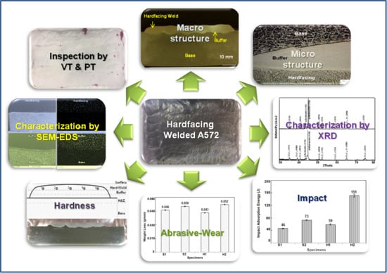
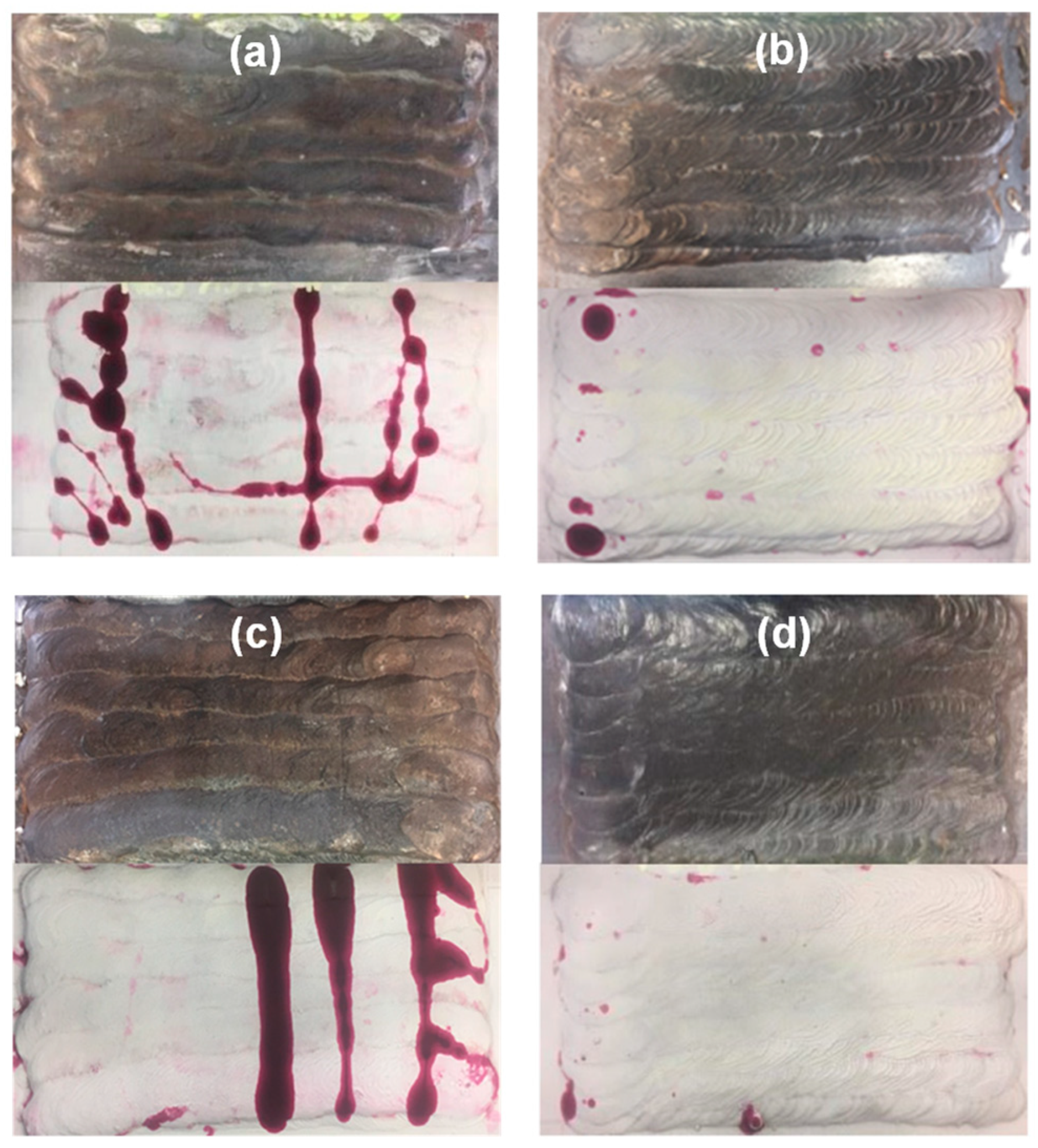
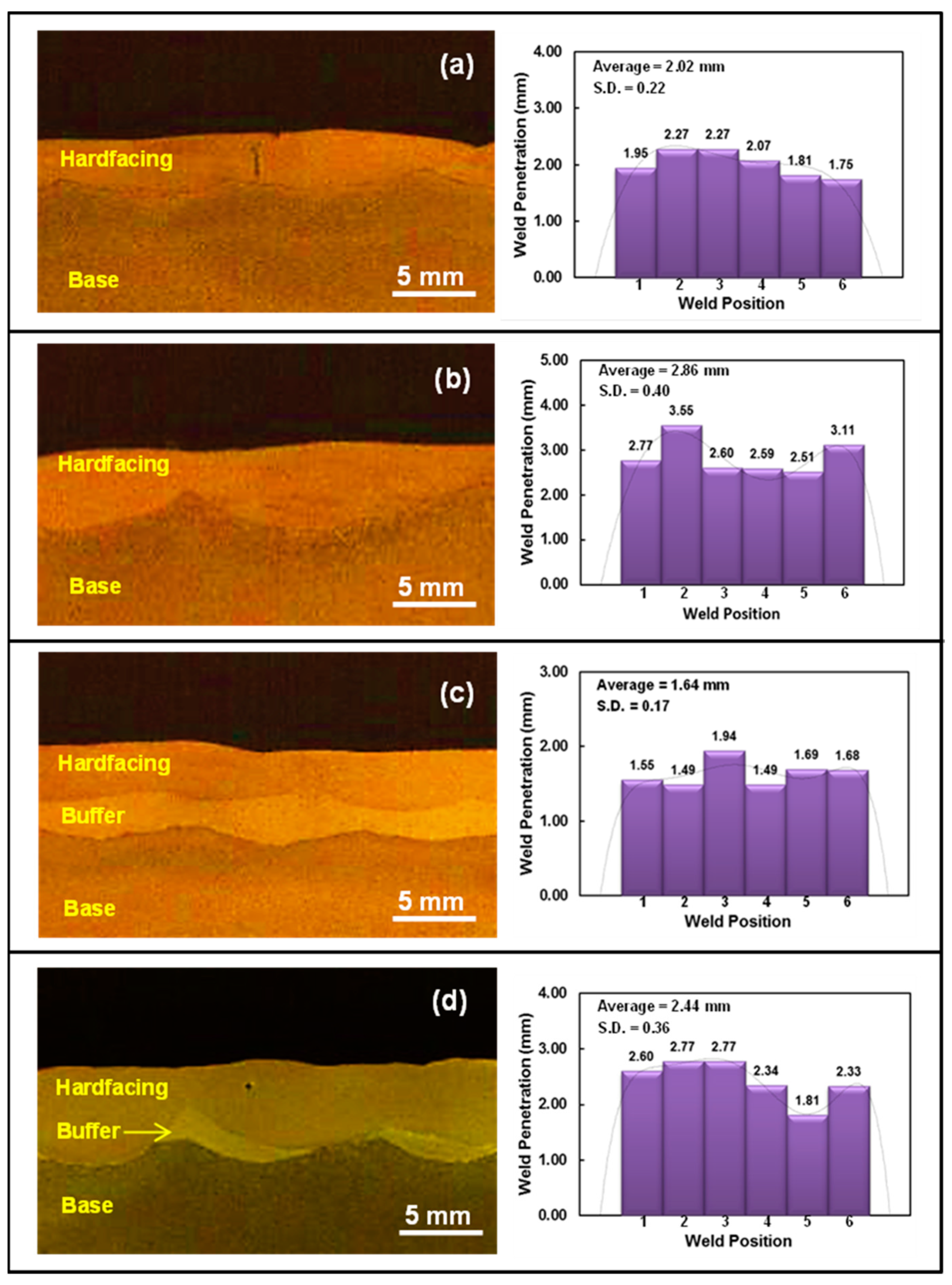
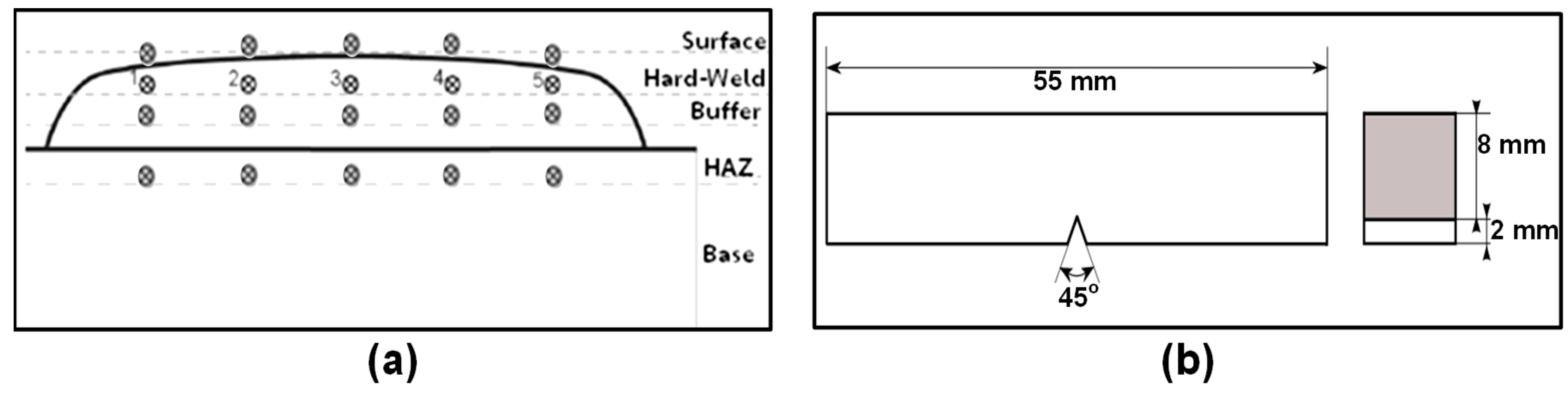
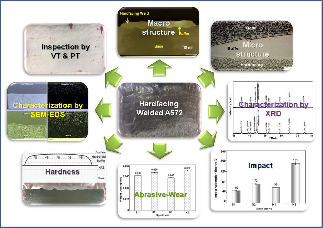
2.3. Hardfacing Welding, Inspection, and Macro–Micro Structure

The buffer and hardfacing electrodes were re-dried before welding for 2 h at 150 °C and 300 °C, respectively [16,18]. The A572 without preheating was used as S1 and H1 specimens, while those preheated at 150 °C for 2 h were labeled as S2 and H2, respectively. In the hardfacing welding process, the specimen was welded by SMAW with the stringer technique, at a flat position. The number of deposited layers (buffer and hardfacing), as well as the welding parameters with heating/cooling conditions are summarized in Table 2. For multiple passes of welding, the interpass temperatures of buffer-based nickel–chromium (Ni–Cr) and chromium hardfacing weld were controlled at 150 °C and 400 °C, respectively [15]. After welding, the S1 and H1 specimens were cooled down in ambient conditions without controlling the cooling rate (~20 °C/min). In the case of S2 and H2, the specimens were embedded under a vermiculite insulator for controlling the cooling rate of 5 °C/min. All welded specimens were observed for the weld quality by visual and penetrant inspections. In addition, the macro–micro structure of the welded specimens at deposited layers was also investigated.

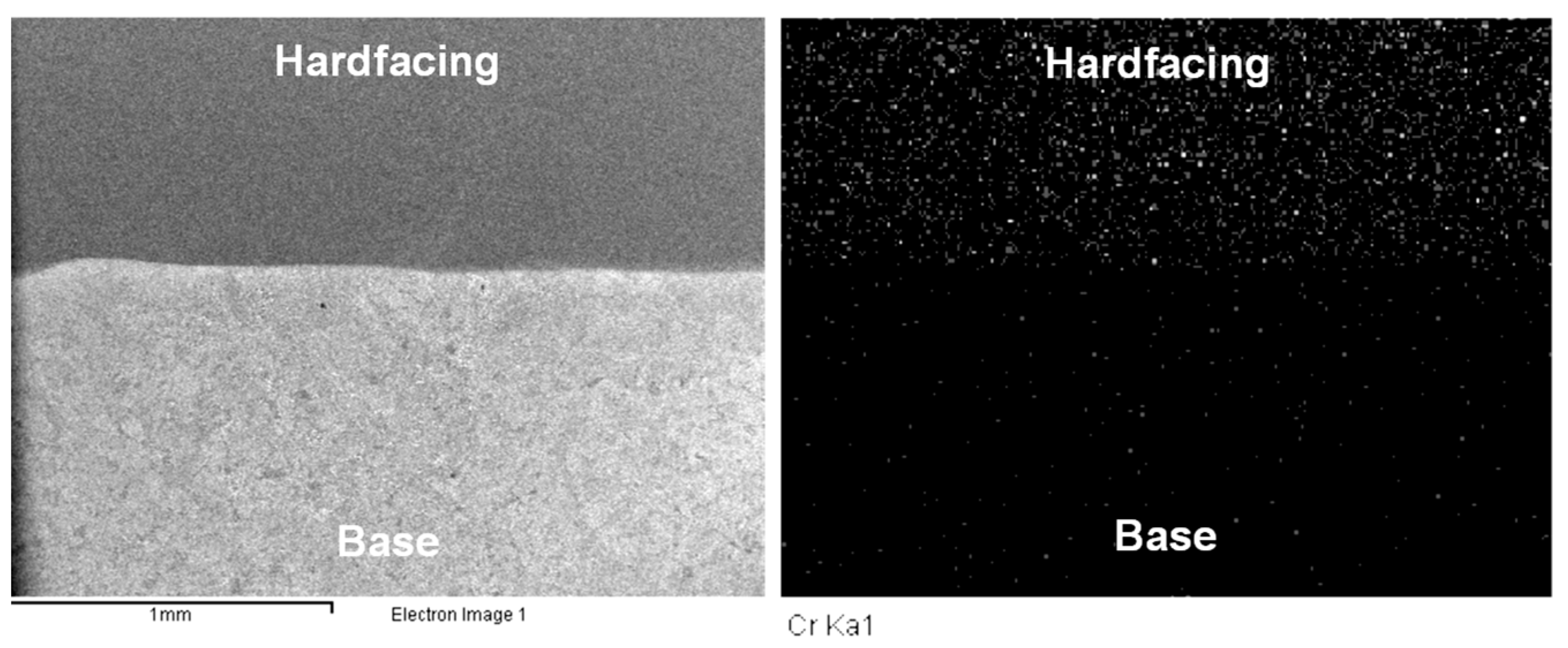
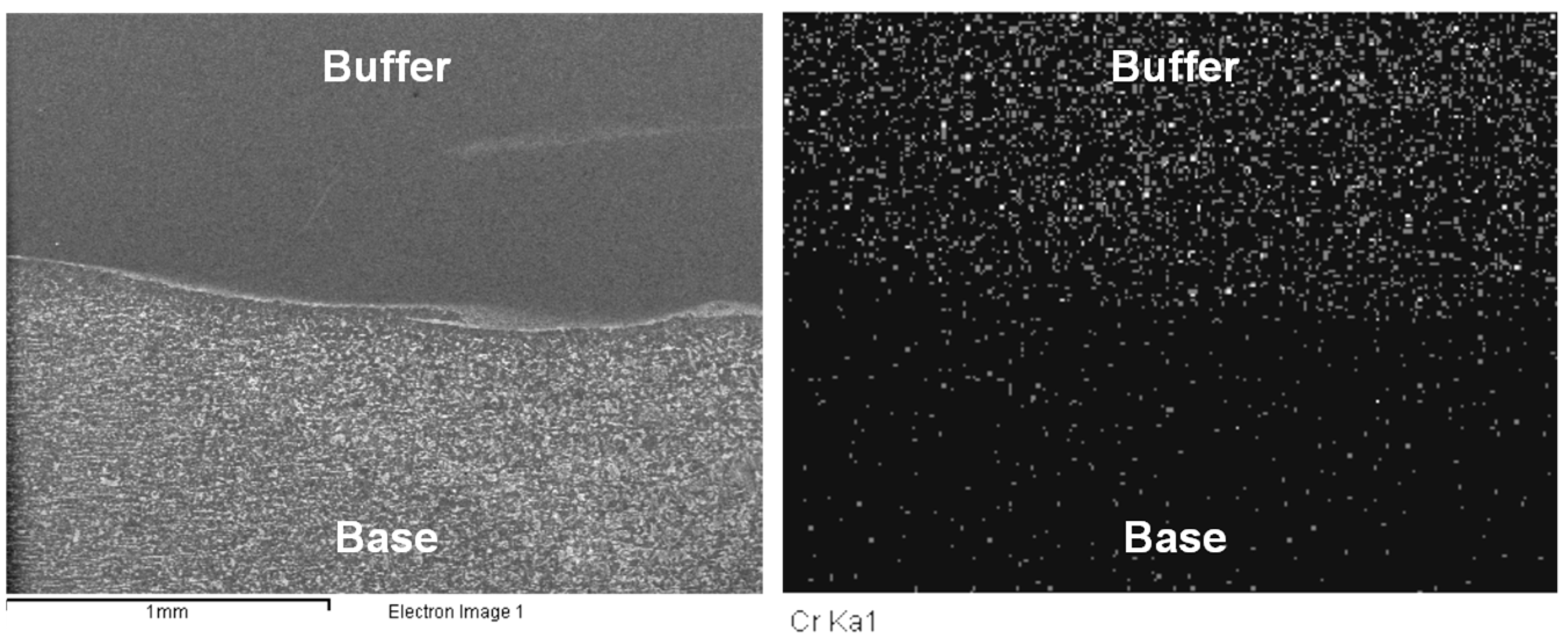
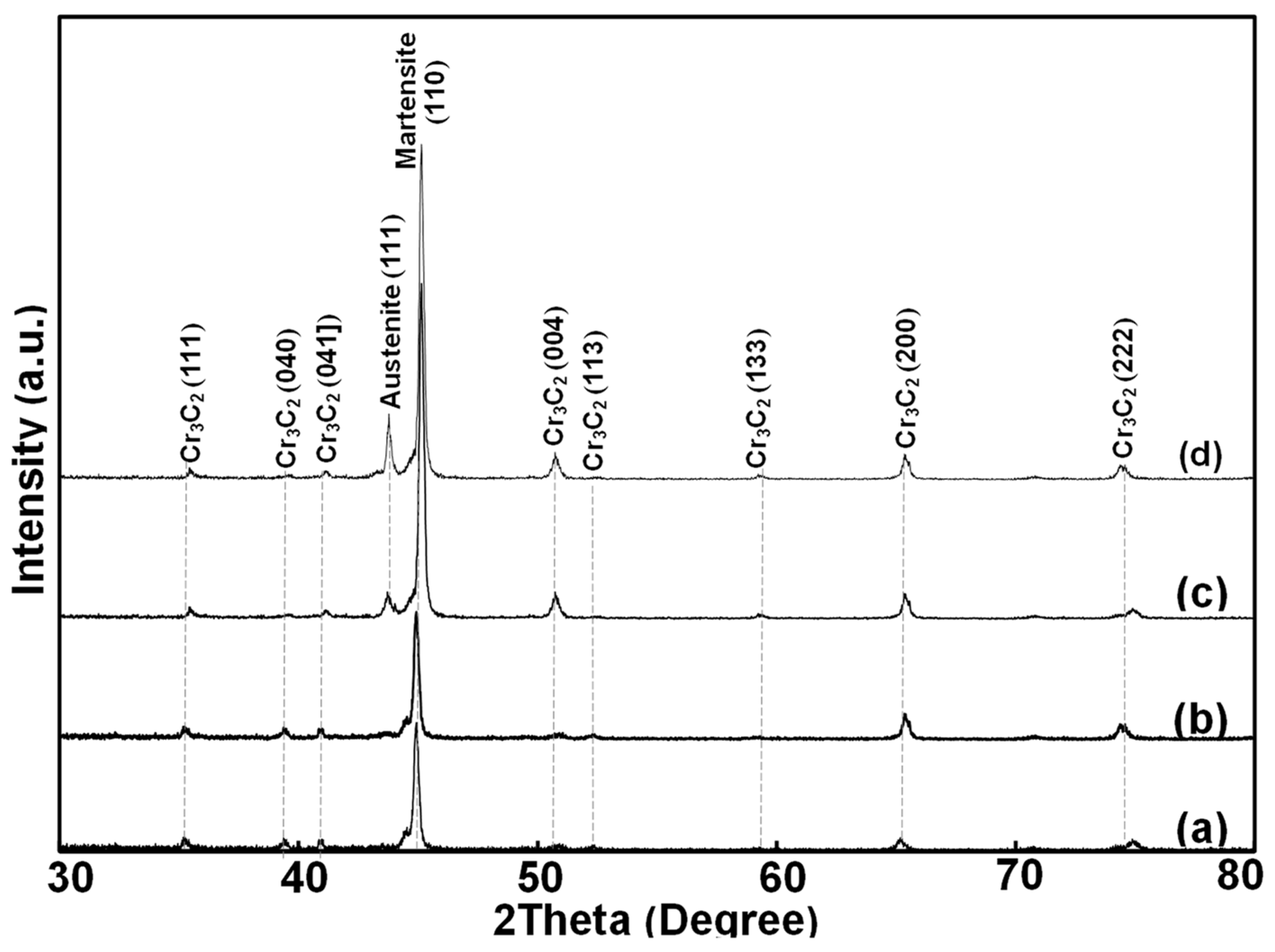
2.4. Structural Characterizations by Scanning Electron Microscope with Energy-Dispersive X-ray Spectrometer and XRD

The elemental composition of the welded specimens at the base, buffer, and hardfacing welding areas was characterized by SEM-EDS. The SEM-EDS with mapping technique was used for studying the compatible elements of the deposited layer. The structural phase of welded specimens was characterized by XRD using Cu-Kα as a radiation source (λ = 1.54 Å), with the 2θ ranging from 30° to 80° at a scanning rate of 0.2 s−1. The crystallite size of the welded specimen was calculated by Scherrer’s equation, as follows:
D = Kλ/βcosθ
where D is the mean size of the ordered (crystalline) domains, which may be smaller or equal to the grain size; K is a dimensionless shape factor with a value of 0.89; λ is the X-ray wavelength; β is the line broadening at half the maximum intensity (FWHM) in radians, after subtracting the instrumental line broadening, which is also sometimes denoted as Δ(2θ); θ is the Bragg angle of the diffraction.

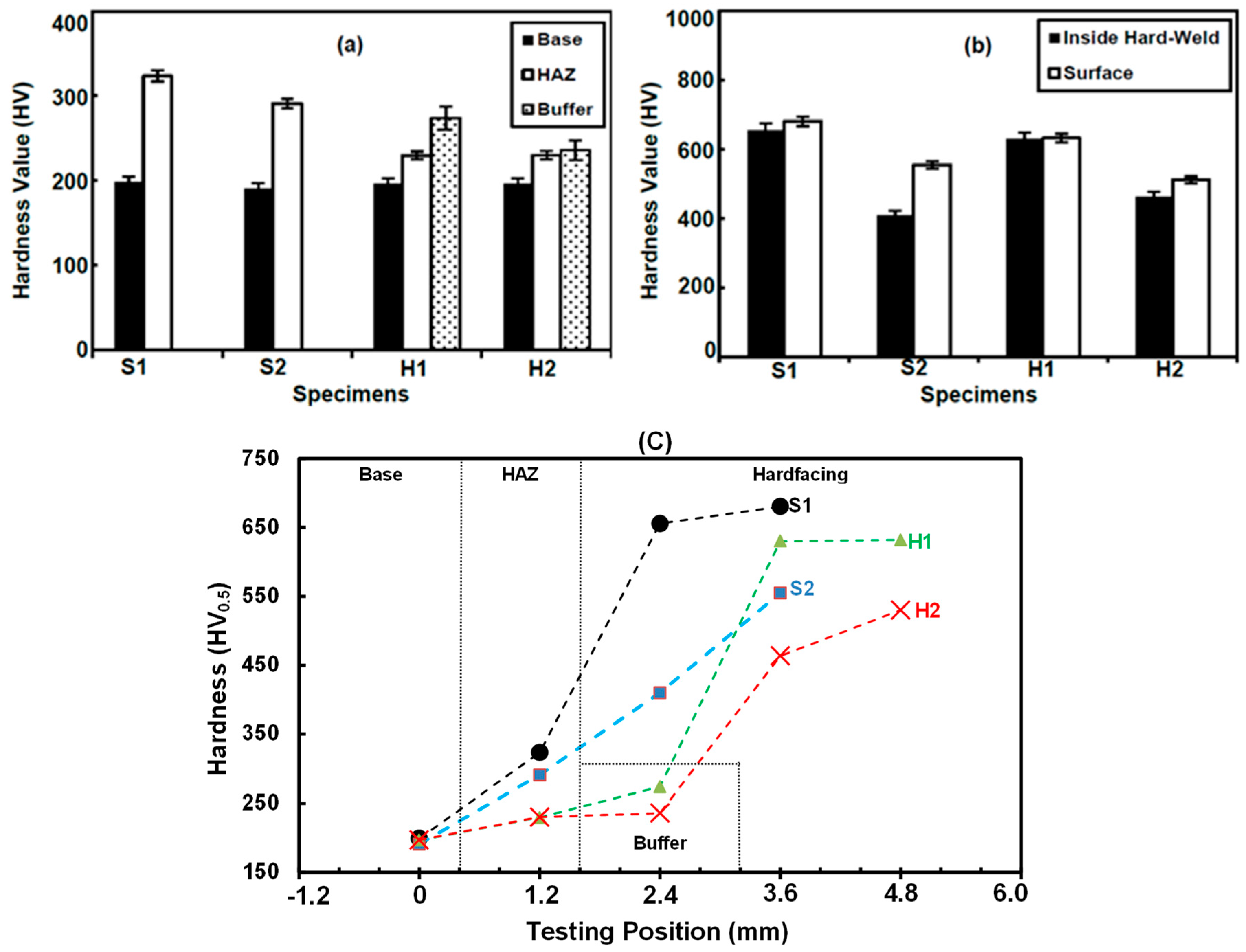
2.5. Hardness, Impact, and Abrasive Wear Properties

The welded specimen was cut into a cross section and tested in five positions for Vickers hardness with load 0.5 kgf. The welded specimen and base metal were prepared in the size of 70 × 25 × 10 mm and further tested for abrasive wear resistance by dry sand rubber wheels, corresponding to the adapted ASTM G65 method with the procedure C (load of 130 N, rotation rate of 200 rpm, and testing time of 30 s) three times, which helps reduce the testing time and accumulated temperature [17]. The abrasive-wear resistance could be considered from weight loss after testing. The welded specimen was prepared as a Charpy V-notch (type A) according to ASTM E23 [21], as shown in Figure 7b, for testing adsorption impact energy at 25 °C.

3. Results and Discussion

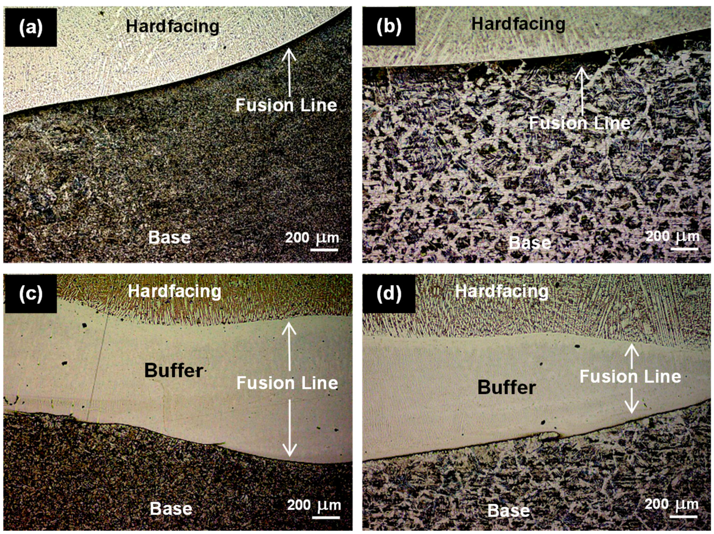
3.1. Hardfacing Welding, Inspection, and Macro–Micro Structure

The visual and penetrant testing results (Figure 1) showed the weld dimension of the specimens (S1, S2, H1, and H2) as approximately 10.0 mm width and 4.0 mm convex. From hardfacing welding, the obtained specimens without heating (S1 and H1) revealed a lot of cracks on the weld (Figure 1a,c). This could be explained in that this welding condition caused residual stress on the hardfacing weld from thermal-volumetric expansions [13]. For welding with preheating and cooling conditions, the welded specimens (S2 and H2) have no planar or critical defects on the surface (Figure 1b,d). This result clearly indicates that preheating and controlling temperature could reduce the critical defects from hardfacing welding, as reported elsewhere [8,9,15].
The deposited layers of hardfacing welded specimens (S1, S2, H1, and H2) were investigated by an optical microscope, as shown in Figure 2 and in the Supplementary Materials (Figure S1). The weld penetration on the base metal of S1, S2, H1, and H2 was determined, and found to be 2.02, 2.86, 1.64, and 2.44 mm, respectively. This implies that the specimens without heating/cooling control (S1 and H1) have a weld penetration lower than those with temperature control (S2 and H2). Moreover, the macroscopic results of H1 (Figure 2c) clearly show the separated layers of base, buffer, and hardfacing, while those of H2 (Figure 2d) exhibit the homogeneous fusion between buffer and hardfacing layers. From the macroscopic results, it might be concluded that hardfacing welding with heating/cooling control could increase the weld penetration. For cooling control, it is possible to get better stresses distribution and values in the buffer layer and melted zones between the base material and buffer, but also between buffer and surface layer.
As shown in Figure 3a–d, the microstructure of the base metal at the heat affect zone (HAZ), both with and without heating/cooling control, showed the mixed phases between ferrite and pearlite. It revealed that the heating/cooling control and hardfacing welding condition had no effect on the structural phase of base metal. However, it was found that the non-heating specimens (S1, H1) showed finer and smaller grains compared to those with heating/cooling control (S2, H2), as shown in the Supplementary Materials (Figure S2). This indicates that the additional heat could increase the grain size of microstructure in the HAZ zone. In the buffer layer, the microstructure of H specimens (Figure 3c,d) showed an austenitic phase, with a small dendritic structure at the grain boundaries (Supplementary Materials, Figure S3). For the hardfacing zone, the microstructure of specimens (Supplementary Materials, Figure S4) clearly showed a martensitic matrix with probably some small austenite fields at the grain boundaries. The dendrite structure (brighten) was denoted as chromium carbide.
At the fusion line (interphase), the S specimens showed a large fusion line from the assembly of carbon elements, due to the low diffusion of carbon elements into the base metal. In the case of H specimens, it was found that the fusion at interphase was observed as a tiny line, indicating that the austenitic buffer layer could help combine and homogenize the elemental components at the interfacial region between base metal and hardfacing material. In addition, the orientation of dendrite shape corresponded to the movement from hardfacing to the buffer layer, clearly indicating the dispersion and dissolution of chromium carbide from hardfacing to the austenitic buffer layer. From macro-microscopic results, it can be clearly concluded that hardfacing welding using a buffer with heating/cooling control could increase the penetration and diffusion of a deposited layer to the base metal.

3.2. Structural Characterization by Scanning Electron Microscope with Energy-Dispersive X-ray Spectrometer and XRD

From the SEM-EDS analysis, the EDS spectrum (Supplementary Materials, Figure S5) at the base metal area showed the peak position of iron (Fe), carbon (C), and manganese (Mn). The spectrum of the buffer layer exhibited the signal of iron, chromium (Cr), nickel (Ni), and manganese. The peaks of iron, chromium, carbon, and silicon (Si) were found in the spectrum of the hardfacing zone. In addition, a chromium element at the interlayer region of the S1 (welding without heating/cooling control, without buffer) and H2 specimens (welding with buffer and heating/cooling control) were analyzed by EDS mapping for consideration of elemental compatibility and dispersion, as shown in Figure 4 and Figure 5, respectively.
For the elemental results of the S1 specimen, it was found that the semi-quantitative amount of carbon content (4.28%) was rather high, which increases the risk of generating defects after welding. In addition, the amount of manganese in S2 (Mn, 1.16%) was in the range of A572-50 specification [1]. This indicates the incompatibility of hardfacing material and base metal, and means the manganese in the base metal could not diffuse into the hardfacing layer. For the base metals of S2 and H2, the relative carbon contents were found to be very low (0.22% and 0.21%, respectively) compared to that of S1, which indicates that the welding with heating/cooling control had no effect on the carbon composition in the base metal. In addition, the manganese in H1 (Mn, 1.56%) and H2 (Mn, 1.60%) was slightly higher than the limit of ASTM A572-50 specification [1] showing the possibility of elemental diffusion from the buffer into the base metal. From these results, it might be concluded that the buffer layer could help improve the welding quality by increasing the elemental diffusion and compatibility between buffer material and base metal.
For S1, the SEM-EDS mapping (Figure 4) clearly showed chromium (Cr), the main element in hardfacing weld, which was separated from base metal. This demonstrates that the weld and base metal had low compatibility, and is related to the microscopic results, which explained that the welding without a buffer layer caused a large fusion line of carbon content and a high barrier for chromium carbide diffusion. Figure 5 shows the SEM-EDS mapping of H2 with the dispersion of Cr in the areas of base metal buffer and hardfacing zone. This result indicates that the buffer layer could help improve the weldability and weld quality of the base metal by increasing the Cr diffusion and compatibility between base metal, buffer, and hardfacing layer.
Phase components of hardfacing welded specimens with and without heating/cooling control (S1, S2, H1, and H2) were characterized by X-ray diffraction. The XRD results of H1 and H2 are showed in Figure 6c,d, respectively. The resulting XRD patterns of the hardfacing welds of H1 and H2 show the peaks of chromium carbide (Cr3C2; ICDD (International Centre for Diffraction Data), No. 03-065-0897), which correspond to the orthorhombic crystal structure. In addition, the peaks at 2θ around 43° and 45° were assigned to the signals of austenite (γ-Fe-C; ICDD No. 33-0397), and martensite (Fe-C; ICDD No. 65-4899), respectively. In the case of S1 and S2, the XRD patterns (Figure 6a,b) showed the diffraction peaks that correspond to martensitite and Cr3C2; no peak of austenite was observed. This result confirmed that the austenite peak of H1 and H2 was from the buffer layer. The structural phase of the hardfacing layer was Cr3C2 and martensite, while that of the austenite was obtained from the buffer layer on the base metal. The ratio of austenitic to martensitic and Cr3C2 of was considered, and the results found that the H1 showed a lower ratio than that of the H2 specimen. This confirmed that the heating/cooling control could help combine the austenitic and martensitic phase and help improve the dilution of buffer and hardfacing layers. Moreover, the good combination of austenitic and martensitic phase in H2 should have had an effect on the hardfacing welded specimen, and it gave no crack in the weld.
From crystallite size calculations at the 2θ of 43° for martensite, 45°for austenite, and 65° for Cr3C2 of the H1 specimen, the crystallite sizes were found to be 43.00, 43.19, and 47.43 nm, respectively. For the H2 specimen, the crystallite sizes of martensite, austenite, and Cr3C2 were found to be 61.44, 60.37, and 64.82 nm, respectively. The results clearly demonstrate that the crystallite size of martensite, austenite, and Cr3C2 is in nano-range, and that heating/cooling control during the welding process made the crystal structure grow to be the larger size, which decreases stress and increases weldability.

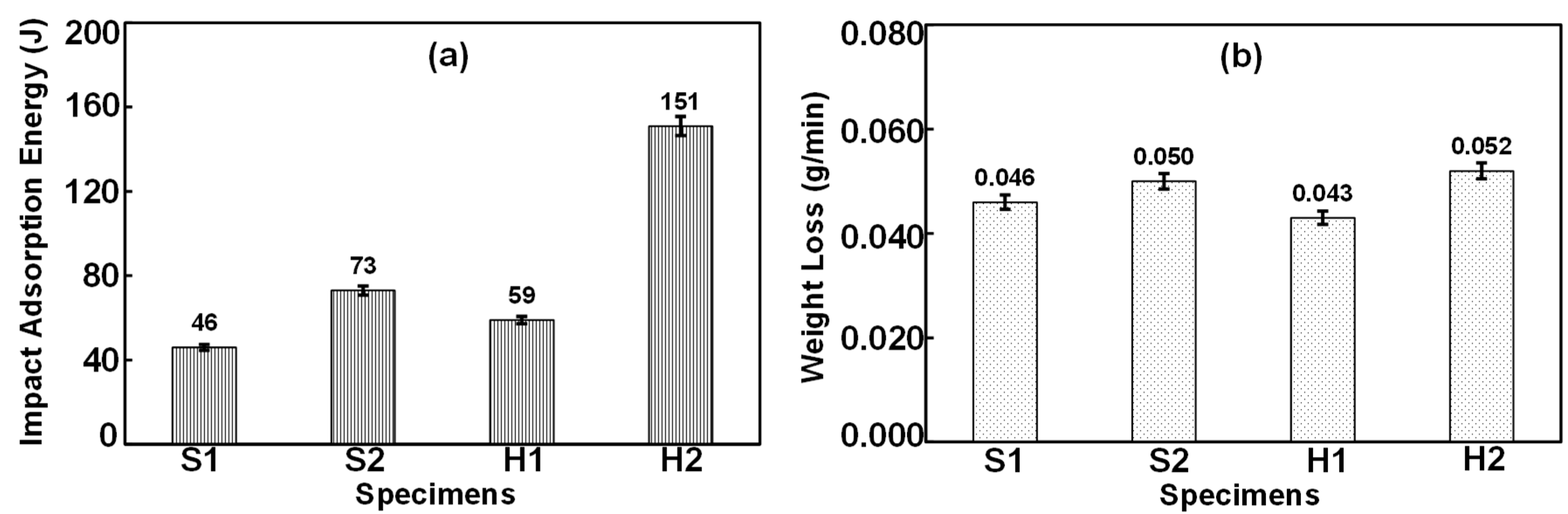
3.3. Hardness, Impact, and Abrasive Wear Properties

The average hardness of all specimens (S1, S2, H1, and H2) in five positions of each area (Figure 7) were observed and compared, as shown in Figure 7 and Figure 8. In the case of the base area, the hardness value of hardfacing welded specimens were found to be around 191–199 HV. This result indicates that the welding process has no effect on hardness at the base area. The welded specimens without buffer layers S1 and S2 showed hardness at heat affected zone (HAZ) values of 323.4 and 290.8 HV, respectively, which are higher than the hardness value (229.7–230.0 HV) of specimens with a buffer layer (H1–H2), as shown in Figure 8a. Based on this result and microstructure, it might be explained that the buffer layer could prevent the direct diffusion of carbon from the hardfacing layer to the HAZ, due to the elemental compatibility of metals such as Cr, Ni, Mn, and Si between the buffer and hardfacing materials, which has the effect of decreasing the hardness. Considering the hardness at the buffer area of H2, it was found that the buffer welding with temperature control showed the hardness value approximately as 235.8 HV, which was close to the hardness of HAZ. On the other hand, the buffer welding without temperature control of H1 showed the hardness value of 273.8 HV, which is higher than that of the hardness of HAZ. This result suggests that the temperature control in welding could better help balance the hardness between the HAZ and buffer than welding without temperature control.
The hardness of hardfacing weld at the surface and its interior to 2 mm (Inside Hard-Weld) were tested, as shown in the Figure 8b. The hardness of S1 and H1 specimens (non-heating/cooling condition) was found to be in the range of 630–655 HV at the inside of the weld, and found to be 631–680 HV at the surface area. For the hardness value of specimens with heating/cooling conditions, it was found that the hardness of S2 and H2 was found to be 410 and 463 HV at the inside of the weld, respectively, and 554 and 511 HV at the surface area, respectively. Figure 8c shows the hardness profile of welded specimens, and finds that the H2 specimen showed the minimum rate of increasing hardness (from base to hardfacing zones). This result clearly indicates that the heating/cooling condition during welding decreased the hardness at the hardfacing weld, because the additional heating during the welding made large grain and crystal sizes, which can relieve stress [22,23,24] and increase weldability at the weld of materials. In addition, the surface hardness of H2 was lower than those of S1, S2, and H1, because the buffer could cause the dilution between buffer and hardfacing materials, resulting in increasing the grain size of microstructure, which reduces the hardness of hardfacing surface.
For impact testing, the impact adsorption energy of welded specimens, S1, S2, H1, and H2, were found to be 46, 73, 59, and 151 joules, respectively, as shown in Figure 9a. It was found that the S1 specimen without buffer and non-heating/cooling control showed an adsorption energy lower than that of the welded specimen (H1) obtained from buffer hardfacing without temperature control. This indicates that the buffer could improve the impact property, because the buffer material consisted of Ni, which could improve the impact property of steels [25]. In addition, the specimens from heating/cooling control (S2 and H2) showed the impact value higher than those S1 and H1 specimens, because the S2 and H2 have a large grain size, which results in high ductility [21]. This result clearly concludes that heating/cooling control during hardfacing can improve the adsorption energy of the weld, which results from decreasing the stress of the weld by increasing the size of the crystal in microstructure.
The A572-50 and welded specimens were tested by a wear testing machine with a dry sand rubber wheel. The wear resistance of all specimens could be determined from the weight loss of the specimen after wear testing, as shown in Figure 9b. From the testing results, it was found that the specimen before welding showed a wear rate of 0.223 g/min, while those of hardfaced specimens exhibited a wear rate of 0.040–0.050 g/min. The results indicate that the hardfacing welding process can help improve the wear resistance of A572-50. When more layers of hardfacing were applied, greater hardness and wear resistance were obtained [10]. Therefore, the hardfacing should carry out two or three hardfacing layers to effectively harden the welded specimen [8,10].

4. Conclusions

The high-strength, low-alloy, steel-based ASTM A572 grade 50 was successfully welded by a hardfacing welding process. For welding with heating/cooling control and buffer, the welded specimens have no critical defects on the surface, which indicates that preheating and controlling temperature with a buffer may reduce the stress in hardfacing welding. From the testing results, the hardfacing welding process with buffer-based Ni-Cr and heating/cooling control could help improve weldability, wear resistance, and adsorption energy. In addition, the XRD results clearly demonstrate that the weld structure was nano-crystalline of martensite, austenite, and Cr3C2. The high austenitic–martensitic ratio might affect the hardfacing welded specimen, which had no cracks. These results indicate that heating/cooling control during the hardfacing welding process made a larger crystalline size, which affected the weldability of specimen. The overall results indicate that the welded specimens from welding with heating/cooling control showed suitable surface properties for wear-resistant applications.

Supplementary Materials

The following are available online at https://www.mdpi.com/2075-4701/9/2/244/s1, Figure S1: Weld penetration of hardfaced specimens: (a) S1, (b) S2, (c) H1 and (d) H1; Figure S2: Microscopic result at HAZ of hardfacing welded specimens: (a) S1, (b) S2, (c) H1 and (d) H2; Figure S3: Microscopic result at buffer of hardfacing welded specimens: (a) H1 and (b) H2; Figure S4: Microscopic result at hardfacing of hardfacing welded specimens: (a) S1, (b) S2, (c) H1 and (d) H2; Figure S5: The EDS spectrum of welded specimen at (a) base, (b) buffer and (c) hardfacing weld.

Author Contributions

N.S. performed research design, grant-materials provision, experiment, data analysis and revised the article. N.K. assisted in experiment and characterization. T.Y. performed materials provision, experiment data analysis and revised the article. A.K. performed research design, characterization, data analysis, wrote and revised the manuscript.

Funding

This research was funded by King Mongkut’s University of Technology North Bangkok, Contract no. KMUTNB-60-ART-030.

Acknowledgments

The authors are very grateful to Department of Materials Engineering, Kasetsart University for supporting X-ray diffractometer. Additional thanks to Vorakorn Thongsang (Thai-German Institute) and Thammanoon Thaweechai (Department of Chemistry, Kasetsart University) for their support of the instruments.

Conflicts of Interest

The authors declare no conflict of interest.

References

  1. ASTM A572/A572M-15: American Society for Testing and Materials (ASTM). Standard Specification for High-Strength Low-Alloy Columbium-Vanadium Structural Steel; ASTM: West Conshohocken, PA, USA, 2015. [Google Scholar]
  2. Desai, S. Plastic Design in A572 (Grade 65) Steel: Mechanical Properties of ASTM A572 Grade 65 Steel. Master’s Thesis, Lehigh University, Bethlehem, PA, USA, 1969. [Google Scholar]
  3. Zhou, J.; Yang, J.; Ye, Y.; Dai, G.; Peng, X. Effect of Heat Input on Microstructure and Properties in Heat Affected Zone of ASTM A572 GR.65 Steel. Adv. Mater. Res. 2011, 148, 553–557. [Google Scholar] [CrossRef]
  4. Doty, W.D. Weldability of constructional steels-USA Viewpoint. Suppl. Weld. J. 1971, 157, 49–57. [Google Scholar]
  5. Shen, Y.F.; Zuo, L. High-strength low-alloy steel strengthened by multiply nanoscale microstructure, HSLA steels 2015. In Micro Alloying 2015 & Offshore Engineering Steels 2015 Conference Proceedings; Springer: Cham, Switzerland, 2015; pp. 187–193. [Google Scholar]
  6. Kenchireddy, K.M.; Jayadeva, C.T.; Sreenivasan, A. Influence of material characteristics on the abrasive wear response of some hardfacing alloys. Glob. J. Eng. Sci. Res. 2014, 1, 12–21. [Google Scholar]
  7. Gómez, A.L.; Cañón, C.F.; Ramírez, D.E. Hard faced welded tips in shredder hammers: Technical and economical performance. Int. Sug. J. 2008, 110, 335–340. [Google Scholar]
  8. Kjellberg, O. Repair and Maintenance Welding Handbook, 2nd ed.; ESAB: Gothenburg, Sweden, 2006; p. 130. [Google Scholar]
  9. O’Brien, A. Welding Processes Part 1, Welding Handbook, 9th ed.; American Welding Society (AWS): Miami, FL, USA, 2004; Volume 2, p. 680. [Google Scholar]
  10. Kumsri, N.; Tippayasam, C.; Srisuwan, N.; Yingsamphancharoen, T.; Kaewvilai, A. Improvement of wear resistant properties of ASTM A572 steel by hardfacing welding process. In Proceedings of the MRS-Thailand International Conference’s E-Proceedings, Chiang Mai, Thailand, 31 October–3 November 2017; pp. 120–124. [Google Scholar]
  11. Lancaster, J.F. Metallurgy of Welding, 6th ed.; Elsevier: Amsterdam, The Netherlands, 1999; p. 464. [Google Scholar]
  12. Yurioka, N. Weldability of modern high strength steels. Adv. Weld. Metall. 1990, 1190, 79–100. [Google Scholar]
  13. Nasir, N.S.M.; Razab, M.K.A.A.; Mamat, S.; Iqbal, M. Review on Welding Residual Stress. ARPN J. Eng. Appl. Sci. 2016, 11, 6166–6175. [Google Scholar]
  14. Srivastava, B.K.; Tewari, S.P.; Prakash, J.A. Review on effect of preheating and/or post weld heat treatmemt (PWHT) on mechanical behaviour of ferrous metals. Int. J. Eng. Sci. Technol. 2010, 2, 625–631. [Google Scholar]
  15. Kobewelding. Available online: http://www.kobewelding.com/SelectingConsumables/hardfacing.pdf (accessed on 7 February 2019).
  16. Bohler-uddeholm. Available online: http://www.bohler-uddeholm.cz/media/UTP%20Maintenance_EN.pdf (accessed on 7 February 2019).
  17. DIN 8555-1, Filler Metals Used for Surfacing; Filler Wires, Filler Rods, Wire Electrodes, Covered Electrodes; Designation; Technical Delivery Conditions; German Institute for Standardisation: Berlin, Germany, 1983.
  18. Bohlerperu. Available online: http://www.bohlerperu.com/images/article/p37_UTP%20LEDURIT%2065.pdf (accessed on 7 February 2019).
  19. Franek, F.; Badisch, E.; Kirchgaßner, M. Advanced methods for characterization of abrasion/erosion resistance of wear protection materials. FME Trans. 2009, 37, 61–70. [Google Scholar]
  20. ASTM G65-16: American Society for Testing and Materials (ASTM). Standard Test Method for Measuring Abrasion Using the Dry Sand/Rubber Wheel Apparatus; ASTM: West Conshohocken, PA, USA, 2016. [Google Scholar]
  21. ASTM E23-18: American Society for Testing and Materials (ASTM). Standard Test Methods for Notched Bar Impact Testing of Metallic Materials; ASTM: West Conshohocken, PA, USA, 2018. [Google Scholar]
  22. Chakrabarty, I. Surface and Heat Treatment Processes. Compr. Mater. Finish. 2017, 2, 246–287. [Google Scholar]
  23. Calcagnotto, M.; Adachi, Y.; Ponge, D.; Raabe, D. Deformation and fracture mechanisms in fine-and ultrafine-grained ferrite/martensite dual-phase steels and the effect of aging. Acta Mater. 2011, 59, 658–670. [Google Scholar] [CrossRef]
  24. Equbal, M.I.; Alam1, P.; Ohdar, R.; Anand, K.A.; Alam, M.S. Effect of cooling rate on the microstructure and mechanical properties of medium carbon Steel. Int. J. Metall. Eng. 2016, 5, 21–24. [Google Scholar]
  25. Gerard, B. Fundamentals of Hardfacing by Fusion Welding, Welding Alloys Group. 2018, pp. 1–37. Available online: https://www.welding-alloys.com/uploads/pdf/brochures/en/wa-consumables/WA%20Hardfacing%20Fundamentals%20by%20arc%20welding.pdf (accessed on 7 February 2019).
Figure 1. Visual (upside) and penetrant (downside) testing results of hardfacing specimens: (a) S1 (without pre-heating), (b) S2 (with pre-heating), (c) H1 (without pre-heating), and (d) H2 (with pre-heating).
Metals 09 00244 g001
Figure 2. Macroscopic results and weld penetration profiles of hardfacing welded specimens: (a) S1, (b) S2, (c) H1, and (d) H2.
Metals 09 00244 g002
Figure 3. Microscopic result of hardfacing welded specimens: (a) S1, (b) S2, (c) H1, and (d) H2.
Metals 09 00244 g003
Figure 4. Scanning electron microscope with energy-dispersive X-ray spectrometer (SEM-EDS) mapping with the Cr element of S1 at the interlayers of the base metal and hardfacing.
Metals 09 00244 g004
Figure 5. SEM-EDS mapping with Cr element of H2 at the interlayers of the base metal and buffer.
Metals 09 00244 g005
Figure 6. XRD Pattern of welded specimens: (a) S1, (b) S2, (c) H1, and (d) H2.
Metals 09 00244 g006
Figure 7. (a) The hardness testing positions and (b) the impact specimen.
Metals 09 00244 g007
Figure 8. The hardness results of welded specimens at the areas of the (a) base, HAZ, and buffer; (b) interior and surface of the hard-weld; and (c) the hardness profiles in various zones of welded specimens (●) S1, () S2, () H1, and () H2.
Metals 09 00244 g008
Figure 9. The testing results of welded specimens: (a) impact and (b) abrasive wear.
Metals 09 00244 g009
Table 1. Elemental composition and hardness of A572 grade 50 steel and welding electrodes.
Materials% Elemental Composition (Fe Balanced)Hardness (HV)
A572 grade 50≤0.23 C≤1.35 Mn≤0.40 Si≤0.05 S≤0.04 P134–137
Buffer Electrode0.10 C19.0 Cr8.50 Ni5.00 Mn0.80 Si194–258
Hardfacing Electrode4.50 C23.5 Cr6.50 Mo5.50 Nb1.50 V594–834
Table 2. Welding parameters.
Specimen No.Preheat Temperature (°C)Deposited Weld LayersInterpass Temperature (°C)Welding ParametersCooling Rate (°C/min)
Current (A)Voltage (V)Travel Speed (mm/min)
S1-Hardfacing-168262020
S2150Hardfacing40016826205
H1-Buffer-106243020
Hardfacing-1682620
H2150Buffer15010624305
Hardfacing4001682620

