Article

The Interfacial Characterization and Performance of Cu/Al-Conductive Heads Processed by Explosion Welding, Cold Pressure Welding, and Solid-Liquid Casting

1
Department of Materials Science and Engineering, Xi′an University of Technology, 5 South Jinhua Road, Xi′an 710048, China
2
Shaanxi Zhituo Solid-State Additive Manufacturing Technology Company, 70 West of Chaoyang Street, Weinan 714000, China
*
Author to whom correspondence should be addressed.
Metals 2019, 9(2), 237; https://doi.org/10.3390/met9020237
Submission received: 4 January 2019 / Revised: 2 February 2019 / Accepted: 13 February 2019 / Published: 16 February 2019

Abstract

:
The Cu/Al composites conductive head is widely used in hydrometallurgy as the core component of cathode plate. Its conductive properties directly affect the power consumption, and the bonding strength and corrosion resistance determine the conductive head service life. The Cu/Al conductive head prepared by explosion welding, cold pressure welding, and solid-liquid casting methods were investigated in this paper. The interface microstructure and compositions were examined by scanning electron microscope and X-ray energy dispersive spectrometry. The bonding strength, interface conductivity, and the corrosion resistance of three types of joints were characterized. The Cu/Al bonding interface produced by explosive welding presented a wavy-like morphology with typical defects and many of brittle compounds. A micro-interlocking effect was caused by the sawtooth structures on the cold pressure welding interface, and there was no typical metallurgical reaction on the interface. The Cu/Al bonding interface prepared by solid-liquid casting consisted mainly of an Al-Cu eutectic microstructure (Al2Cu+Al) and partial white slag inclusion. The thickness of the interface transition layer was about 200–250 µm, with defects such as holes, cracks, and unwelded areas. The conductivity, interfacial bonding strength, and corrosion resistance of the conductive head prepared by explosive welding were superior to the other two.

1. Introduction

Cu/Al composites structures are widely used in electric power, automobiles, electronics, hydrometallurgy, and other fields, due to their corrosion resistance and the light weight properties of Al, as well as the high electrical conductivity, high thermal conductivity, and low contact resistance of Cu [1,2,3,4]. For example, the batteries of electric vehicles require a high number of Cu/Al connections, and the hydrometallurgical cathode plates require Cu/Al composite conductive heads. However, some physical properties of these materials are markedly different, which makes it difficult to weld Al to Cu effectively [5,6]. Furthermore, Cu and Al are relatively negative metals, and they have good intermiscibility [7]. In some temperature regions, they are susceptible to metal brittleness. Certain phases (such as Al2Cu, Al4Cu9, etc.) have a significant effect on the electrical conductivity and bonding strength of the interface [8,9,10,11].
Specifically, the Cu/Al composite conductive head is the core component of cathode plate in the zinc hydrometallurgical system, and it is used in high corrosive environments (acid fog atmosphere) and multiple cold- and hot-cycle (frequent on/off) conditions [12]. Its conductive properties directly affect the power consumption of the zinc hydrometallurgical process, while its bonding strength and corrosion resistance determines the service life of the conductive head. The bonding interface is the weakest area of the Cu/Al conductive head. Its structures are the key factors that determine the ultimate performance of the above conductive head.
Cu/Al composite structure are usually fabricated by explosion welding [13,14,15], cold pressure welding [16], and solid-liquid casting [17]. The different Cu/Al interface structures are obtained by different composite methods. The performances of the conductive heads with different interface structures are different in the zinc hydrometallurgical system. The basic principle of explosive welding consists of taking advantage of the kinetic energy of an explosive placed over a flying plate, which is positioned at a short distance from the stationary plate to be coated. The detonation of the explosive projects the flying plate against the base plate at a very high velocity, causing high pressure at the interface, and establishing the weld [13]. Under the action of severe plastic deformation and vibrational waves, the explosive welding method can produce Cu/Al composite structures with reliable welding quality [18]. However, the large interfacial stress and the regional brittle compound aggregation brought about by this method [19] will produce interfacial cracks in the process of energizing the conductive head. Cold pressure welding is a method where the aluminum and copper pieces are subject to strong pressure at room temperature. The plastic deformation of the welding interface, causing the metal atoms of the workpiece to reach each other’s attractive distance, allows the atoms to diffuse to form a solid phase bond, allows for the formation of a joint [20]. Cold pressure welding is also often used to join Cu and Al to make conductive heads [21]. Cu/Al solid-liquid joining is carried out by a casting method. Molten aluminum with a certain degree of superheat is poured into a cavity where pre-treated copper plates are placed. Then, the sample is cooled in the mold to room temperature [17]. An overwhelming majority of 1.2 m2 cathode conductive heads are produced by the solid-liquid casting method. Although the high interface resistance results in a large voltage drop, it is not easy to exfoliate based on the Al-clad Cu structure design.
This paper focused on the application of a Cu/Al composite structure as a conductive head in the zinc hydrometallurgical system. Cu/Al conductive heads prepared by explosion welding, cold pressure welding and solid-liquid casting methods are investigated. The structure and composition of the Cu/Al interface region are characterized by scanning electron microscopy (SEM) and X-ray energy dispersive spectrometry (EDS). The bonding strengths of three types of joints are characterized by tensile shear testing, and interfacial microhardness distribution is obtained, the resistivity of the three types of joints are estimated, and the accuracy of the measurement technique is verified. The corrosion resistance of the joints is evaluated based on the polarization curve.

2. Materials and Methods

2.1. Experimental Samples

The samples of the Cu/Al cathode conductive head prepared by explosion welding, cold pressure welding, and solid-liquid casting were investigated in this study. Ten Cu/Al cathode conductive heads were prepared by each method. Three samples were randomly selected from each kinds of joints (explosion welding joint, cold pressure welding joint, and solid-liquid casting joint) for analysis and testing. The base materials were commercial T2 Cu (99.9 wt%) and 1060 Al (99.6 wt%). For the Cu/Al explosion welding process, the Cu and Al plates were assembled in parallel as the flying and base plates. The initial distance between them (stand-off distance) was about 1.25 mm. The explosive used in the welding was an emulsion explosive (sensitized with hollow glass microspheres at a proportion of about 15%), using an explosive ratio of 2.1. The detonation velocity was 2100 m/s. The induced impact velocity (Vp = 851 m/s) and β angle (14.3°) were calculated according to the procedure indicated in [18]. For Cu/Al cold pressure welding, the surface treatment before welding was used to remove surface oxide films and impurities. The procedures for cleaning were as follows: sanding the surface with fine sandpaper, pickling in HF solution (10% HF) for 3 min, neutralized with NaOH solution, and then subjected to acetone ultrasonic cleaning for 2 min, which can effectively remove surface impurities and oxide films. The welding pressure of cold pressure welding was 2100 MPa, and the deformation was about 65%. For the Cu/Al solid-liquid casting process, the preheating temperature of the copper plate was 300 °C, and the casting temperature of the aluminum liquid was 700 °C. The preheating temperature of the copper and the casting temperature of the aluminum liquid were determined based on preliminary experimental results and references [22]. All joints were produced in full overlap configuration.

2.2. Analysis Methods

The above three types of joints were cut for section view, and their interface structures and compositions were examined by scanning electron microscopy (SEM, JEOL, JSM-6700, Japan Electronics Co.) equipped with an energy-dispersive spectrum (Oxford INCA, Japan Electronics Co.) with a spectral resolution of 133 eV. The mechanical properties of the joints were evaluated by shear tensile tests (Instron 5880). The microhardness of Cu/Al interfacial transition layer was measured using a TUKON2100 Vickers microhardness tester. The electrical resistance of the joints was tested by a micro-ohmmeter (TEGAM1750, Cleveland, OH, USA), and the resistivity was obtained. Electrochemical tests were performed on a CS 310 electrochemical workstation. The potentiodynamic polarization curve scan range was from −0.5 V to 1 V, and the scan rate was 1 mV/s.

3. Results and Discussion

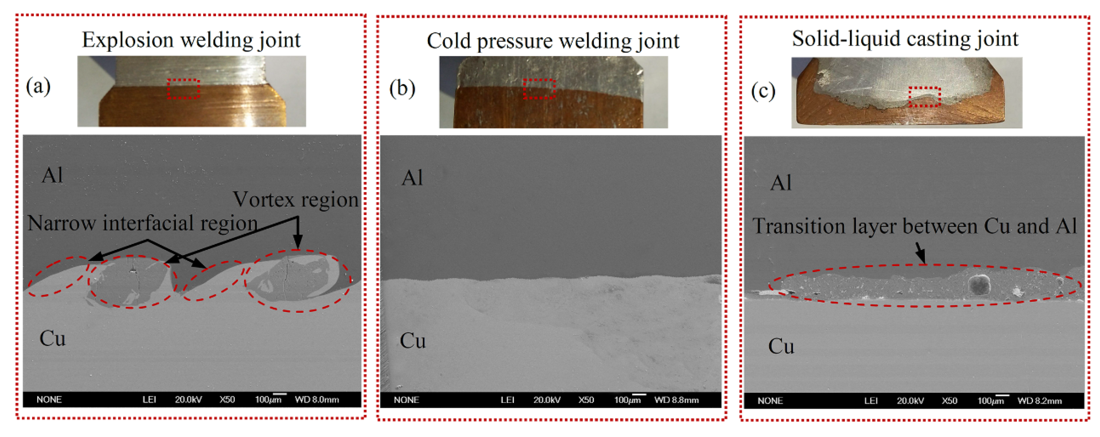
3.1. Joint Appearance and Different Interface Structures

The samples of the Cu/Al cathode conductive head prepared by explosion welding, cold pressure welding, and solid-liquid casting were investigated in this study. Corresponding to the different joining methods, the interface structures were very different. Figure 1 shows the interface macro-appearance and micro-morphologies of the three kinds of interface structures. The explosion welding method was a severe plastic deformation process, in which the thermal shock and severe plastic deformation could accelerate the interface reaction and diffusion, so that metallurgical bonding between Cu and Al metals was finally formed. The appearance of the explosive weld and the typical interface morphology are shown in Figure 1a. It can be observed that the appearance of the explosive weld presented good bonding without typical macro-defects. The bonding interface of the joints presented a wavy-like morphology. The appearance of the cold pressure weld and the micromorphology showed good bonding without typical defects, as illustrated in Figure 1b. However, there was no obvious metallurgical reaction at the interface. The appearance of the solid-liquid casting interface was very distinctive compared to the other two interfaces, as illustrated in Figure 1c. There was a visible layer with uniform thickness between Al and Cu. A number of voids defects with different sizes were presented in the interface zone.

3.2. Microstructures of the Cu/Al Joints

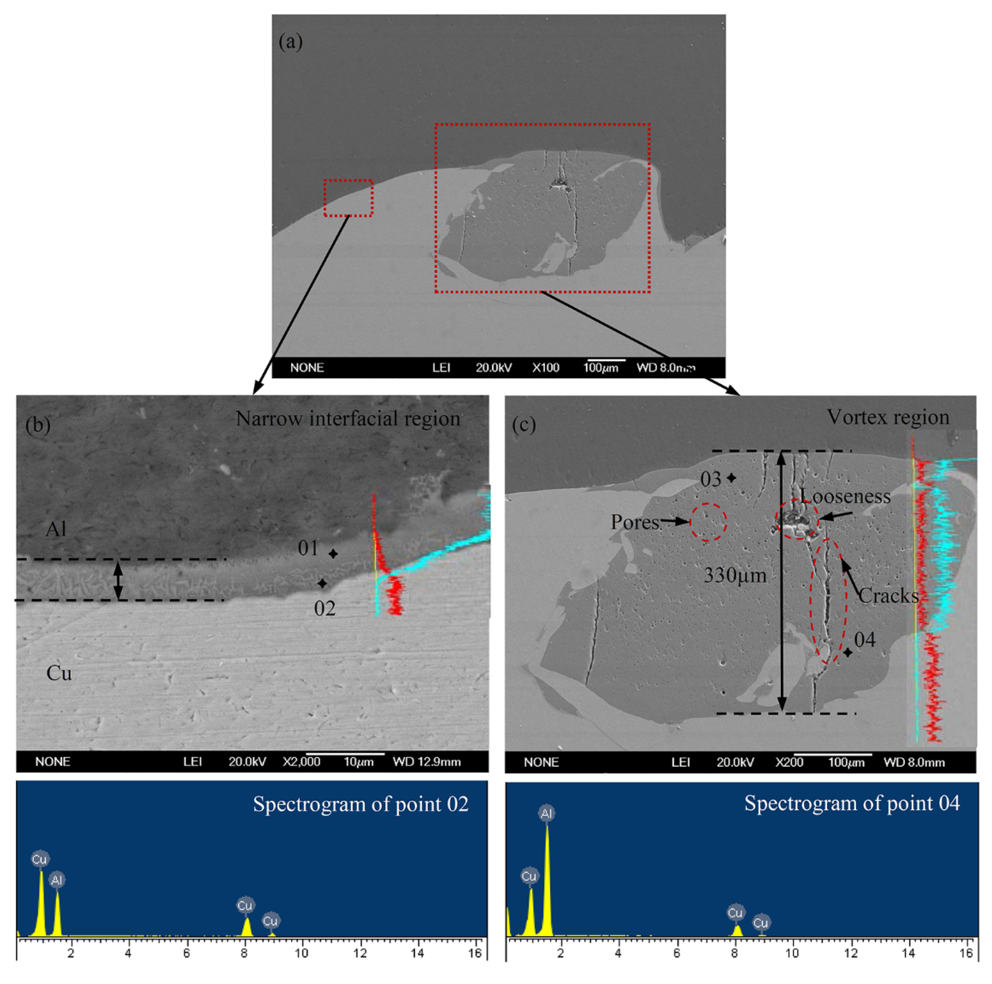
3.2.1. The Microstructure of the Explosion Welding Joint

Figure 2 shows the typical interface morphology of Cu/Al conductive head produced by explosive welding. It could be seen that the bonding interface of the joints presented a wavy-like morphology. There were two distribution patterns on the whole interface. One was the narrow interfacial region without typical defects, and the other was the spiral structure between the compound and the pure metals. At greater magnification, the morphology of the narrow interfacial region is illustrated in Figure 2b. This area presented a good combination feature, and the structural constituent was not evenly distributed. A large number of light gray acicular structures were embedded in a dark gray substrate. More densely distributed light gray acicular structures were presented close to the copper side. An EDS spot scan analysis was used to preliminarily determine the compounds in this area, as shown in Table 1. In view of the atom ratio of Al: Cu, it could be inferred that the area of point 01 near the Al side was an Al-rich solid-solution solid, and the area of point 02, the light gray acicular structures, was a possible Al4Cu9 phase, but this was not accurate enough to allow for the extraction of conclusions about the chemical composition. The line scan components analysis showed a ~5 μm width with a gradual Al element drop off and a Cu element increase from the Al matrix to the Cu matrix, as shown in Figure 2b.
Figure 2c shows the microstructure of the vortex region. This region consisted of a vortex-like structure formed between the compound and the pure metal, which was consistent with [13]. There were typical defects such as pores, cracks, and looseness, as shown in Figure 2c. The micro-morphology analysis of the interface between Cu/Al explosive welding, showed a large deformation at the joining interface, partial melting of the organization, oxide inclusions, pores, and cracks. The interface structure was extremely uneven, and a large number of brittle intermetallic compounds were generated in the vortex-like region. The thickness of this region reached up to approximately 330 μm, and typical defects such as cracking occurred in the compound layer. The Al:Cu atom ratio at the points 03 and 04 indicated that most compounds in the vortex region was possible Al2Cu phases, based on preliminary EDS analysis and XRD phase analysis experiments in [12].

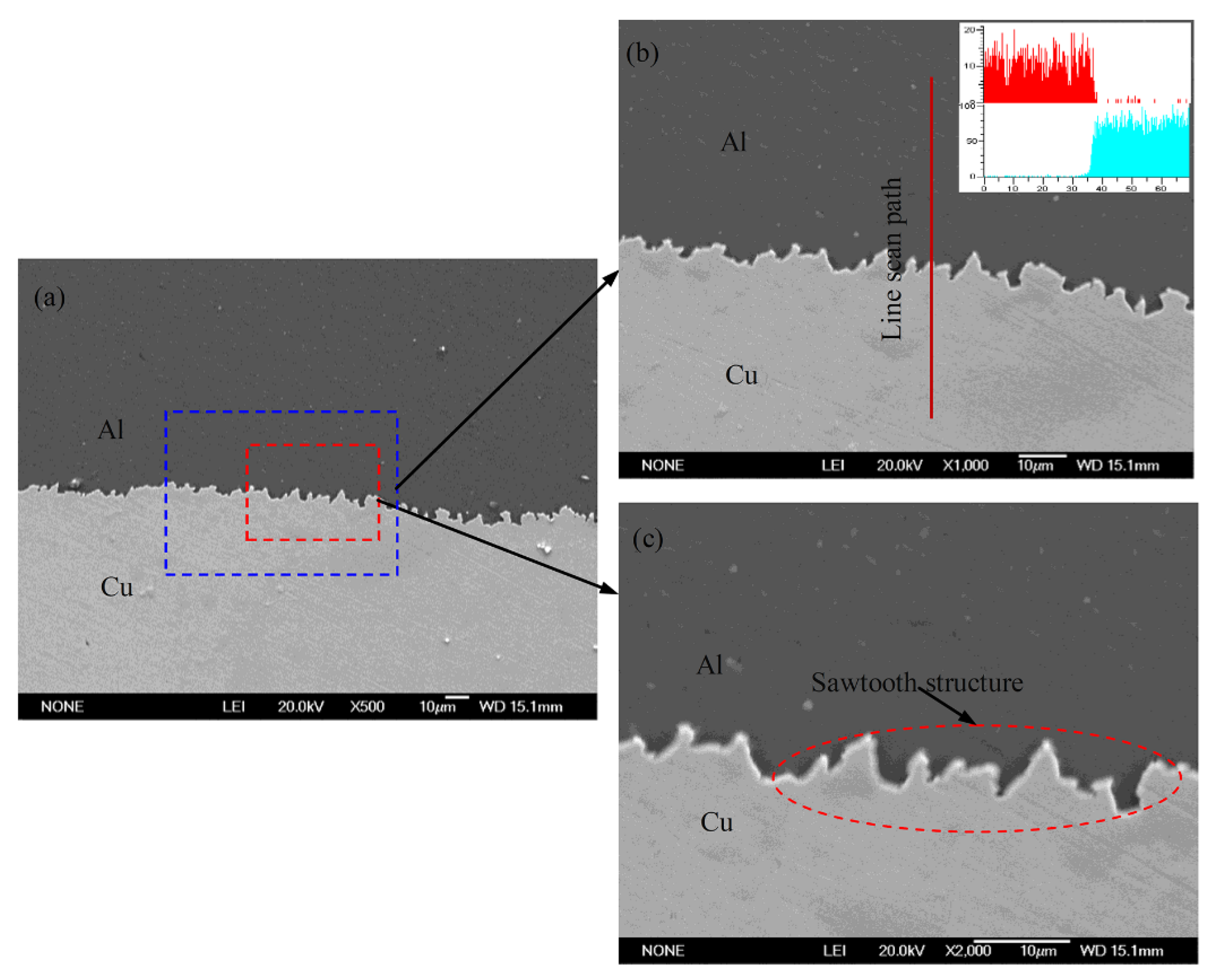
3.2.2. The Microstructure of the Cold Pressure Welding Joint

Figure 3 shows the typical interface morphology of the Cu/Al cathode conductive head produced by cold pressure welding. It could be seen that there was no distinct layer of compounds with distinct gray values on the whole interface. A larger multiple of morphological images with a linear scanning composition distribution of the cold pressure welding interface is shown in Figure 3b. This indicated that there was no obvious diffusion and compound generation during the cold pressure process. However, the interface structure exhibited complex peak and valley morphologies. Serrated interpenetration features, as shown in Figure 3c, were formed on the interface. This sawtooth structures could produce an interlocking effect, which can obviously enhance the bonding strength between Cu and Al [23].

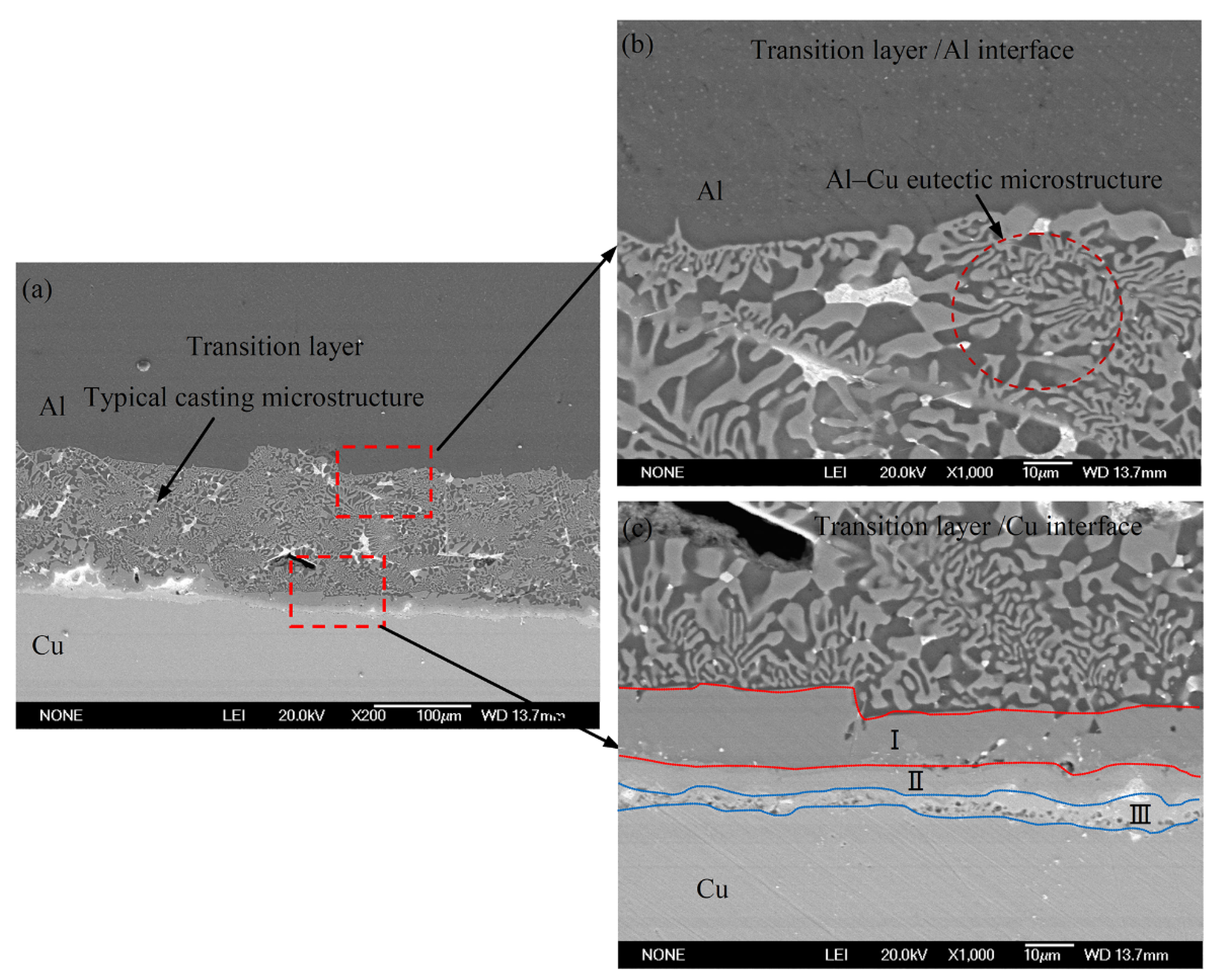
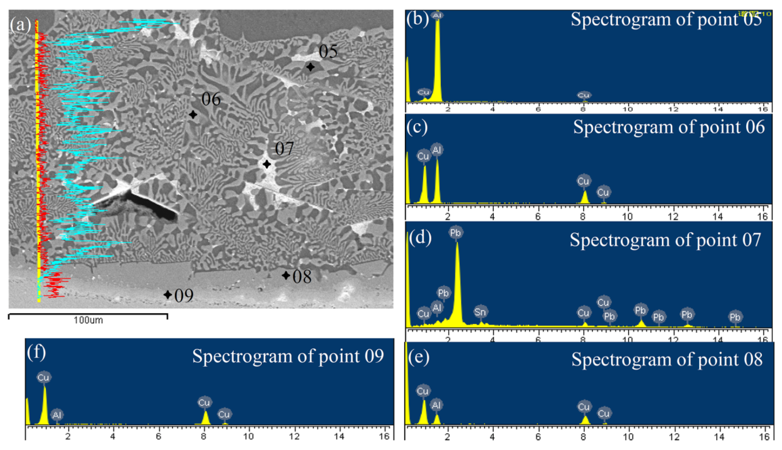
3.2.3. The Microstructure of the Solid-Liquid Casting Joint

For the process of the Cu/Al solid-liquid casting, the mutual diffusion and reaction between liquid aluminium and solid copper formed a metallurgical bond with a certain degree of thickness in the transition layer. Figure 4 showed the typical interface morphology of the Cu/Al cathode conductive head produced by solid-liquid casting. It could be found that the transition layer consisted mainly of an Al-Cu eutectic microstructure (Al2Cu+Al) and a partial white slag inclusion. The Al2Cu phase presented a continuous reticular structure that was widely distributed in interfacial transition layer. Figure 4b,c respectively show the detailed microstructure of the transition layer/Al interface and the transition layer/Cu interface. The transition layer/Al interface shows the irregular intercalation characteristics between the Al matrix and the compound, as shown in Figure 4b. In contrast, the transition layer/Cu interface presented a layered distribution with different grayscale values, as illustrated in Figure 4c. There were three distinct layers (I, II and III, shown in Figure 4c) between the reticular structure and the Cu metal matrix. Layers I and II showed uniform structural characteristics. However, dense hole defects were distributed in the III layer region. The width of the interface transition layer of the solid-liquid casting was approximately 200–250 μm.
Figure 5 showed the distribution of elements that are perpendicular to the interface, and the point component of the analysis spectrogram shown in the solid-liquid casting joint. It could be found that the content of Al and Cu elements were changed consistent with the change of microstructure. EDS spot scan analysis was carried out to determine the possible composition of different regions. The corresponding spectrogram of the different points is shown in Figure 5b–f. The results of the EDS analysis conducted on points 05–09 in Figure 5a are shown in Table 2. This indicates that the reticular zone consisted of an Al matrix (the region of point 05), Al2Cu (the region of point 06) and the slag inclusion (the region of point 07). The layer near the reticular structure (corresponding to layer I in Figure 4c) could be identified as the AlCu phase in view of the atom ratio (n(Al):n(Cu)) that was approximately equal to 1:1 in the positions of point 08. In Layer II, point 09 was a copper matrix with a small amount of Al. This indicated that part of the surface layer of the copper matrix was eutectically melted during the casting of the aluminum liquid.

3.3. The Performance of the Cu/Al Joints with Different Interface Structures

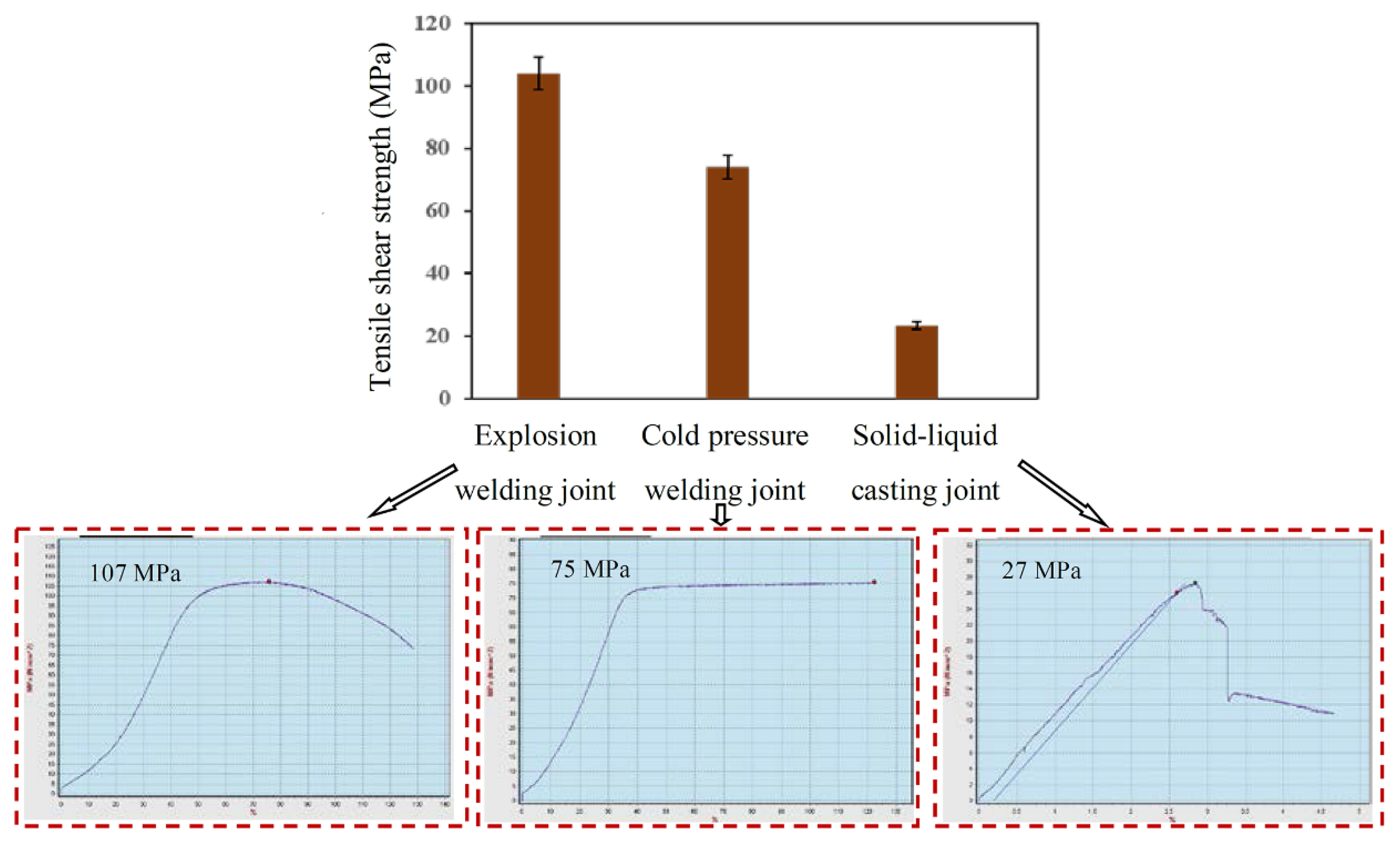
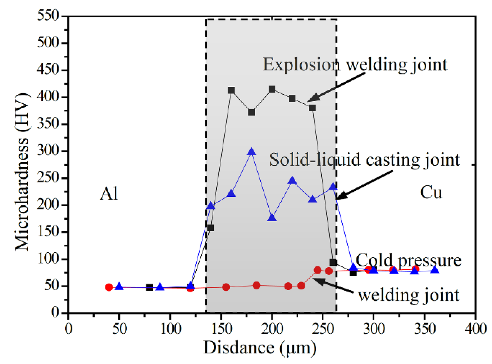
3.3.1. Tensile Strength and Microhardness Distribution of the Joints

Interface bonding strength is of great importance the for Cu/Al conductive head in practical applications. The shear strength of three types of Cu/Al conductive heads were tested, and the fracture mechanisms was analyzed. In this paper, three test samples were selected for each process, and two tensile shear samples were prepared from each test sample. Therefore, there were six tensile samples for each process. The specimens were cut into Φ 10 mm × 40 mm, consisting of half Al and half Cu. The shear strengths and the typical stress-strain curves are shown in Figure 6. It could be seen from the figure that the interface shear strength of the explosive welding Cu/Al joint was the highest, with an average value 104 MPa. This was mainly because of the good metallurgical bonding and special interface structures present. The interfacial shear strength of the joint prepared by cold pressure welding method was about 74 MPa. This might be provided by the special interlocking structures at the interface, although there was no obvious metallurgical bonding layer between Al and Cu. The interface shear strength of the Cu/Al conductive head prepared by the solid-liquid casting method was the lowest, about 23.5 MPa. This was mainly due to the obvious defects of the Cu/Al composite interface which contained mainly shrinkage, porosity, inclusions, and intermetallic compounds near the Cu side. The eutectic structure with a large degree of thickness at the interface, and its obvious solidification defects such as shrinkage holes and inclusions, resulted in a high resistance from the interface transition layer, and serious power consumption when energized.
Because the thickness of Cu/Al transition layer was usually below the millimeter-level, microhardness was chosen. In this paper, the microhardness of Cu/Al interfacial transition layer was measured using the TUKON2100 Vickers microhardness tester. The loading was 10 g and the dwell time was 10 s. The microhardness distributions of the three kinds of interface structures were obtained, as shown in Figure 7. The transition layer of the explosive welding joint had a microhardness range of 372–413 HV. The transition layer of the solid-liquid casting joint had a microhardness range of 176–298 HV. It could be seen that the microhardness of the transition layer on the interface of Cu/Al conductive head prepared by explosive welding and solid-liquid casting was much higher than that of the matrix. The value depended on the composition and microstructure. Also, the width of the high-hardness region was consistent with that of the interfacial transition layer. The microhardness of the Cu/Al interfacial transition layer prepared by cold pressure welding did not increase significantly, mainly because no obvious metallurgical reactions were found on the interface.

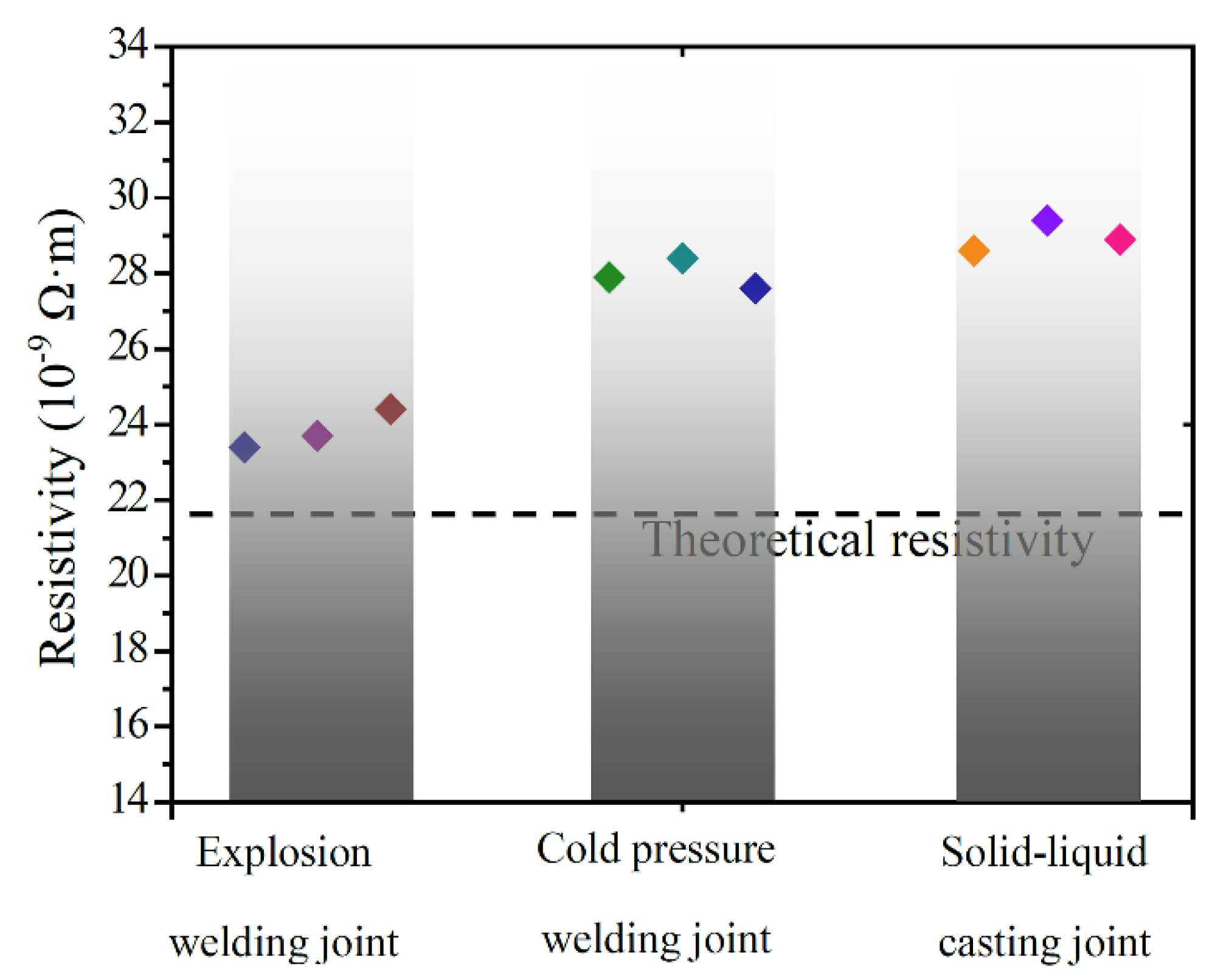
3.3.2. The Resistivity of the Joints

Considering that Cu and Al were all materials with good conductivities, they offered very little electrical resistance. The TEGAM 1750 microhmmeter with a resolution for 0.1 µΩ was used. The samples sizes for the resistance test were 5 mm in diameter and 10 mm in length, with Al and Cu each accounting for half the volume. The resistivity of the joint was estimated by the equation ρ = RS/L, where R is the electrical resistance, S is the sectional area, and L is the specimen length. The TEGAM 1750 microhmmeter utilized the "four-wire test" to eliminate the influence of the lead and contact electrical resistance. The absolute error of the electrical resistance (R), tested by the TEGAM 1750 microhmmeter was 0.1 µΩ. The specimen diameter (d) and length (L) were measured by a spiral micrometer with an absolute error of 0.01 mm. The resistivity was calculated by the equation ρ = RS/L = Rπd2/(4L). The relative error of the resistivity can be estimated as: δρ = ΔR/R + 2Δd/d + ΔL/L = 0.1/11 + 2(0.01/5) + 0.01/10 = 1.41%.
The resistivities of three types of Cu/Al joints were estimated and are shown in Figure 8. According to the binary metal resistivity formula (as shown in equation 1/r = VAl/rAl + VCu/rCu, where r is the theoretical resistivity, VAl, VCu, rAl, rCu are the volume fraction of Al (50%), the volume fraction of Cu (50%), Al resistivity (measured value 28.4 × 10⁻⁹ Ω·m), and Cu resistivity (measured value 17.5 × 10⁻⁹ Ω·m)), respectively and related values, and the theoretical resistivity of the Cu/Al bimetallic composite structures r = 21.6 × 10⁻⁹ Ω·m. It was be found that the resistivity of the explosion welding joint was about 24 × 10−9 Ω·m which was slightly higher than the theoretical resistivity. The resistivity of cold pressure welding and the solid-liquid casting joint was about 28 × 10−9 Ω·m, which was close to that of the Al metal. Compared with Cu and Al, the intermetallic compounds had a high resistivity (such as Al2Cu 80 × 10−9 Ω·m and A14Cu9 142 × 10−9 Ω·m). The presence of the intermetallic compounds will increase the resistivity of the Cu/Al bimetallic composite structures.

3.3.3. The Corrosion Resistance of the Joints

The standard electrode potential of Al was −1.66 V, while that of Cu was +0.34 V. The electrode potential of Al and Cu differed greatly, and serious electrochemical corrosion effects occurred in the corrosive atmosphere, which would lead to the failure of the conductive head. The same size with Al and Cu, each accounting for half the volume of the three interface structures, were used to assess their corrosion resistance. The interface polarization curve was shown in Figure 9. The calculated corrosion potential and corrosion current density are shown in Table 3. It could be seen that the self-corrosion current density of the explosive welding sample was the smallest, and its corrosion rate was slow. The self-corrosion current density of the casting sample was the largest, and its corrosion resistance was the worst, which was mainly caused by its poor bonding quality and a large number of interface defects.

3.4. Comparative Analysis of the Cu/Al Joints with Different Interface Structures

As a conductive component, the Cu/Al conductive head was used in high corrosive environments and in multiple cold- and hot-cycle conditions. The conductive properties directly affected the power consumption, while the bonding strength and corrosion resistance determined the service life of the conductive head. The bonding interface was the weakest area. Its structures were the key factors that determined the ultimate performance of the conductive head.
Based on the above results, it could be found that good metallurgical bonding with a wavy-like morphology was obtained on the Cu/Al explosive welding interface. Under the action of a severe plastic deformation and a vibration wave, the explosive welding method can produce Cu/Al composite structures with reliable welding qualities. The good metallurgical bonding and the large entangled vortex structure greatly improved the interface bond strength, although there were micro-cracks in the vortex region. The shear strength could reach about 104 MPa with the fracture being located on the Al matrix. Furthermore, the good metallurgical bonding interface also gave it better electrical conductivity and corrosion resistance.
The microstructure of the joint prepared by cold pressure welding showed that there was no obvious metallurgical reaction layer on the interface. The shear strength of the joint was about 74 MPa, which was mainly due to the mechanical joining of the sawtooth structure formed during the cold pressure process. Therefore, the interface conductivity was poor, which would result in serious heating from resistance during use. The Cu/Al bonding interface prepared by solid-liquid casting consisted mainly of Al-Cu eutectic microstructures (Al2Cu+Al) with defects such as holes, cracks, and unwelded areas. The conductivity, interfacial bonding strength, and corrosion resistance were all relatively poor. Therefore, in practical applications, Cu/Al conductive heads prepared by explosion welding have the best application performance.

4. Conclusions

The main motivation of this article was to evaluate the interfacial characterization and performance of the conductive head prepared by explosion welding, cold pressure welding, and solid-liquid casting methods. The interface microstructure and compositions were examined. The bonding strength and the interfacial microhardness distributions were obtained. The resistivities of the three types of joints were estimated, and the accuracy of the measurement technique was verified. The corrosion resistances of the joints were evaluated based on the polarization curve. The main conclusions are as follows:
(1)
The bonding interface of the Cu/Al cathode conductive head produced by explosive welding presented a wavy-like morphology, which contain a narrow interfacial region (the width about ~5 μm) and a vortex region (the width about ~330 μm). A micro-interlocking effect was formed by a saw-tooth structure on the cold pressure welding interface, with no obvious metallurgical reaction. The Cu/Al bonding interface prepared by solid-liquid casting consisted mainly of Al-Cu eutectic microstructures (Al2Cu+Al) and partial white slag inclusions (a width of about 200–250 μm) with typical defects such as holes, cracks, and unwelded areas.
(2)
Under the action of severe plastic deformation and vibration waves, the explosive welding Cu/Al joint had reliable welding quality (104 MPa) based on good metallurgical bonding and mechanical joining. The resistivity of the explosion welding joint was relatively low. The Cu/Al cold pressure welding joint strength (74 MPa) was a result of special interlocking structures with higher resistivities due to poor interfacial metallurgical bonding. Poor shear strength and electrical conductivity of the Cu/Al solid-liquid casting joint was mainly due to obvious interface defects.
(3)
It can be concluded that the conductivities, interfacial bonding strengths, and corrosion resistances of the conductive heads prepared by explosive welding were superior to the other two, and it has the best application performance as a conductive head.

Author Contributions

Conceptualization, Y.W. and F.S.; Investigation, H.L.; Resources, J.Z.; Writing—original draft, Y.W.

Funding

This work is financially supported by the National Natural Science Foundation of China under Grant no. 51701154, the Key Research and Development Project of Shaanxi Province under Grant no. 2017ZDXM-GY-033 and 2018ZDXM-GY-136, the China Postdoctoral Science Foundation-Funded Project under Grant no. 2016M592823 and the Scientific Research Project of Shaanxi Provincial Department of Education under Grant no. 17JK0563.

Acknowledgments

The authors would like to thank Shaanxi Province Key Laboratory of Electrical Materials and Infiltration Technology (Xi’an University of Technology, Xi’an 710048, China) for providing some experimental materials, and the Yunnan Chihong Zinc and Germanium Co., Ltd., (QuJing 655011, Yunnan, China) for providing practical applications for conductive heads.

Conflicts of Interest

The authors declare no conflict of interest.

References

  1. Huang, G.Q.; Hou, W.T.; Li, J.P.; Shen, Y.F. Development of surface composite based on Al-Cu system by friction stir processing: Evaluation of microstructure, formation mechanism and wear behavior. Surf. Coat. Technol. 2018, 344, 30–42. [Google Scholar] [CrossRef]
  2. Xiong, J.; Peng, Y.; Zhang, H.; Li, J.; Zhang, F. Microstructure and mechanical properties of Al-Cu joints diffusion bonded with Ni or Ag interlayer. Vacuum 2018, 147, 187–193. [Google Scholar] [CrossRef]
  3. Khan, H.A.; Wang, K.F.; Li, J.J. Interfacial bonding mechanism and mechanical properties of micro friction stir blind riveting for multiple Cu/Al ultra-thin layers. Mater. Charact. 2018, 141, 32–40. [Google Scholar] [CrossRef]
  4. Liu, J.; Cao, B.; Yang, J.W. Effects of Vibration Amplitude on Microstructure Evolution and Mechanical Strength of Ultrasonic Spot Welded Cu/Al Joints. Metals 2017, 7, 471. [Google Scholar] [CrossRef]
  5. Raoelison, R.N.; Racine, D.; Zhang, Z.; Buiron, N.; Marceau, D.; Rachik, M. Magnetic Pulse Welding: Interface of Al/Cu Joint and Investigation of Intermetallic Formation Effect on the Weld Features. J. Manuf. Process. 2014, 16, 427–434. [Google Scholar] [CrossRef]
  6. Liu, G.P.; Hu, X.W.; Fu, Y.S.; Li, Y.L. Microstructure and Mechanical Properties of Ultrasonic Welded Joint of 1060 Aluminum Alloy and T2 Pure Copper. Metals 2017, 7, 361. [Google Scholar] [CrossRef]
  7. Celik, S.; Cakir, R. Effect of friction stir welding parameters on the mechanical and microstructure properties of the Al-Cu butt joint. Metals 2016, 6, 133. [Google Scholar] [CrossRef]
  8. Kim, H.G.; Kim, S.M.; Lee, J.Y.; Choi, M.R.; Choe, S.H.; Kim, K.H.; Ryu, J.S.; Kim, S.; Han, S.Z.; Kim, W.Y.; Lim, S.L. Microstructural Evaluation of Interfacial Intermetallic Compounds in Cu Wire Bonding with Al and Au Pads. Acta Mater. 2014, 64, 356–366. [Google Scholar] [CrossRef]
  9. Xu, H.; Liu, C.; Silberschmidt, V.V.; Pramana, S.S.; White, T.J.; Chen, Z.; Acoffa, V.L. Behavior of Aluminum Oxide, Intermetallics and Voids in Cu-Al Wire Bonds. Acta Mater. 2011, 59, 5661–5673. [Google Scholar] [CrossRef]
  10. Lee, W.B.; Bang, K.S.; Jung, S.B. Effects of intermetallic compound on the electrical and mechanical properties of friction welded Cu/Al bimetallic joints during annealing. J. Alloys Compd. 2005, 390, 212–219. [Google Scholar] [CrossRef]
  11. Mao, Z.P.; Xie, J.P.; Wang, A.Q.; Wang, W.Y.; Ma, D. Interfacial Characterization and Bonding Properties of Copper/Aluminum Clad Sheets Processed by Horizontal Twin-Roll Casting, Multi-Pass Rolling, and Annealing. Metals 2018, 8, 645. [Google Scholar] [CrossRef]
  12. Wei, Y.N.; Luo, Y.G.; Qu, H.T.; Zou, J.T.; Liang, S.H. Microstructure evolution and failure analysis of an aluminum–copper cathode conductive head produced by explosive welding. J. Mater. Eng. Perform. 2017, 26, 1–9. [Google Scholar] [CrossRef]
  13. Loureiro, A.; Mendes, R.; Ribeiro, J.B.; Leal, R.M.; Galvão, I. Effect of explosive mixture on quality of explosive welds of copper to aluminium. Mater. Des. 2016, 95, 256–267. [Google Scholar] [CrossRef]
  14. Asemabadi, M.; Sedighi, M.; Honarpisheh, M. Investigation of cold rolling influence on the mechanical properties of explosive-welded Al/Cu bimetal. Mater. Sci. Eng. A 2012, 558, 144–149. [Google Scholar] [CrossRef]
  15. Acarer, M. Electrical, Corrosion, and Mechanical Properties of Aluminum-Copper Joints Produced by Explosive Welding. J. Mater. Eng. Perform. 2012, 21, 2375–2379. [Google Scholar] [CrossRef]
  16. Woźniak, H. The results of the so far performed investigations of Al-Cu butt cold pressure welding by the method of upsetting. Arch. Civ. Mech. Eng. 2009, 9, 135–145. [Google Scholar] [CrossRef]
  17. Liu, G.; Wang, Q.D.; Zhang, L.; Ye, B.; Jiang, H.Y.; Ding, W.J. Effect of Cooling Rate on the Microstructure and Mechanical Properties of Cu/Al Bimetal Fabricated by Compound Casting. Metall. Mater. Trans. A 2018, 49, 661–672. [Google Scholar] [CrossRef]
  18. Hoseini Athar, M.M.; Tolaminejad, B. Weldability window and the effect of interface morphology on the properties of Al/Cu/Al laminated composites fabricated by explosive welding. Mater. Des. 2015, 86, 516–525. [Google Scholar] [CrossRef]
  19. Denisov, V.; Saykov, I.V.; Kapustin, R.D. Explosion welding of Al + Cu bimetallic joints for electrical contacts. Weld. Int. 2017, 31, 773–776. [Google Scholar] [CrossRef]
  20. Eslami, P.; Karimi Taheri, A.; Zebardast, M.A. Comparison between Cold-Welded and Diffusion-Bonded Al/Cu Bimetallic Rods Produced by ECAE Process. J. Mater. Eng. Perform. 2013, 22, 3014–3023. [Google Scholar] [CrossRef]
  21. Zare, G.R.; Divandari, M.; Arabi, H. Investigation on interface of Al/Cu couples in compound casting. Mater. Sci. Technol. 2013, 29, 190–196. [Google Scholar] [CrossRef]
  22. Tanaka, Y.; Kajihara, M.; Watanabe, Y. Growth behavior of compound layers during reactive diffusion between solid Cu and liquid Al. Mater. Sci. Eng. A 2007, 445–446, 355–363. [Google Scholar] [CrossRef]
  23. Zhang, W.; Shen, Y.F.; Yan, Y.F.; Guo, R. Dissimilar friction stir welding of 6061 Al to T2 pure Cu adopting tooth-shaped joint configuration: Microstructure and mechanical properties. Mater. Sci. Eng. A 2017, 690, 355–364. [Google Scholar] [CrossRef]
Figure 1. The interface macro-appearance and micro-morphologies of three kinds of interface structures, shown as: (a) explosion welding joint, (b) cold pressure welding joint and (c) solid-liquid casting joint.
Metals 09 00237 g001
Figure 2. The typical interface morphology of Cu/Al cathode conductive head produced by explosive welding, shown as: (a) the interface microstructure, (b) the narrow interfacial region, and (c) the vortex region.
Metals 09 00237 g002
Figure 3. The typical interface morphology of the Cu/Al cathode conductive head produced by cold pressure welding, shown as: (a) a typical interface microstructure, (b) the elemental distribution of the vertical interface, and (c) the sawtooth structure.
Metals 09 00237 g003
Figure 4. The typical interface morphology of Cu/Al cathode conductive head produced by solid–liquid casting shown as: (a) the overall characteristics of the interface, (b) the microstructure of the transition layer/Al interface and (c) the microstructure of the transition layer/Cu interface.
Metals 09 00237 g004
Figure 5. The distribution of elements perpendicular to the interface and the point component analysis spectrogram of the solid-liquid casting joint shown as: (a) the distribution of elements, (b) spectrogram of point 05, (c) spectrogram of point 06, (d) spectrogram of point 07, (e) spectrogram of point 08 and (f) spectrogram of point 09.
Metals 09 00237 g005
Figure 6. The shear strengths of three kinds of interfaces, and the corresponding stress–strain curve.
Metals 09 00237 g006
Figure 7. The microhardness distribution across different interface structures.
Metals 09 00237 g007
Figure 8. The resistivities of three types of Cu/Al joints.
Metals 09 00237 g008
Figure 9. The interface polarization curve of three kinds of joints shown as: (a) explosion welding sample, (b) cold pressure welding sample and (c) solid-liquid casting sample.
Metals 09 00237 g009
Table 1. EDS point analysis results of the location in Figure 2 (at %).
Test PositionsAlCuAl:CuPossible Phase
0181.8618.144.5:1Al-rich solid solution
0229.3270.684:9Al4Cu9
0368.2631.742:1Al2Cu
0469.1730.832:1Al2Cu
Table 2. Composition analyses of the points indicated in Figure 5 (at%).
Test PositionsAlCuSnPbPossible Phase
0598.051.95Al metal
0667.8032.20Al2Cu
079.5217.3962.9910.10Slag inclusion
0848.9551.05AlCu
095.3294.68Cu metal
Table 3. The corrosion potential and the corrosion current density in Figure 9.
Sample TypesCorrosion Current Density (A/cm2)Corrosive Potential/V
Explosion welding1.616 × 10−6−0.75925
Cold pressure welding1.609 × 10−7−0.6879
Solid-liquid casting8.456 × 10−6−0.79061
4.456 × 10⁻⁵−1.014

