Manufacturing and Evaluation of Multi-Material Axial-Bearing Washers by Tailored Forming


 , ,
, ,
Abstract
:1. Introduction and Motivation
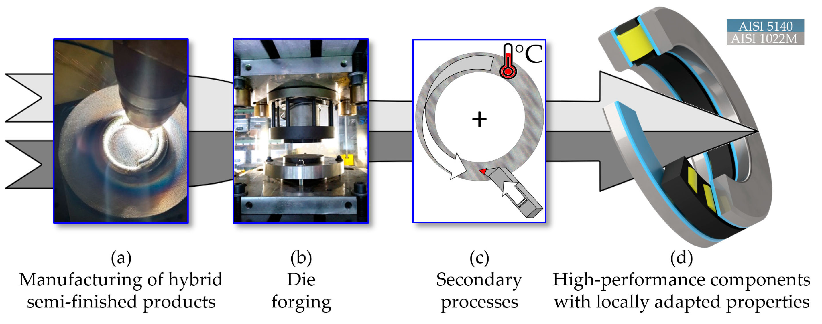
2. Process Chain for the Manufacture of a Hybrid Axial Bearing Washer
3. Methodology for the Production of Hybrid Axial Bearing Washers
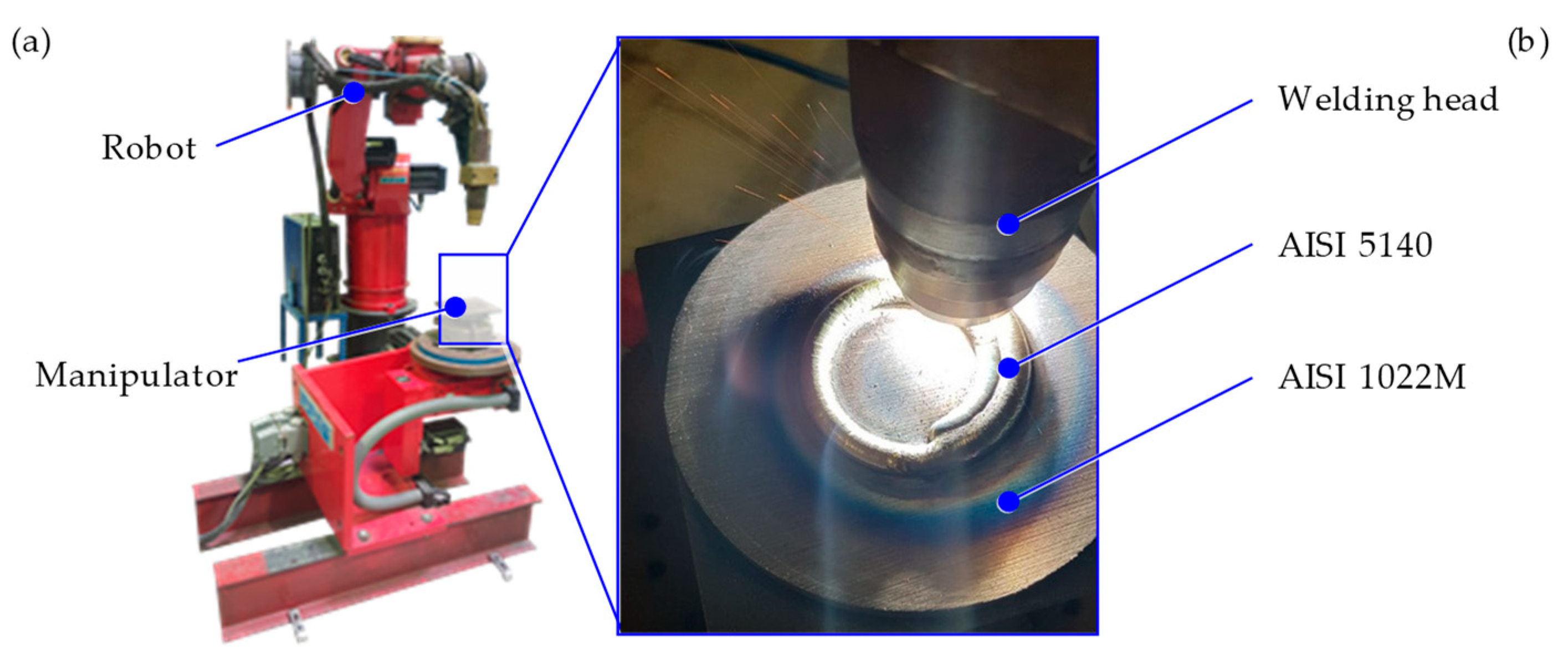
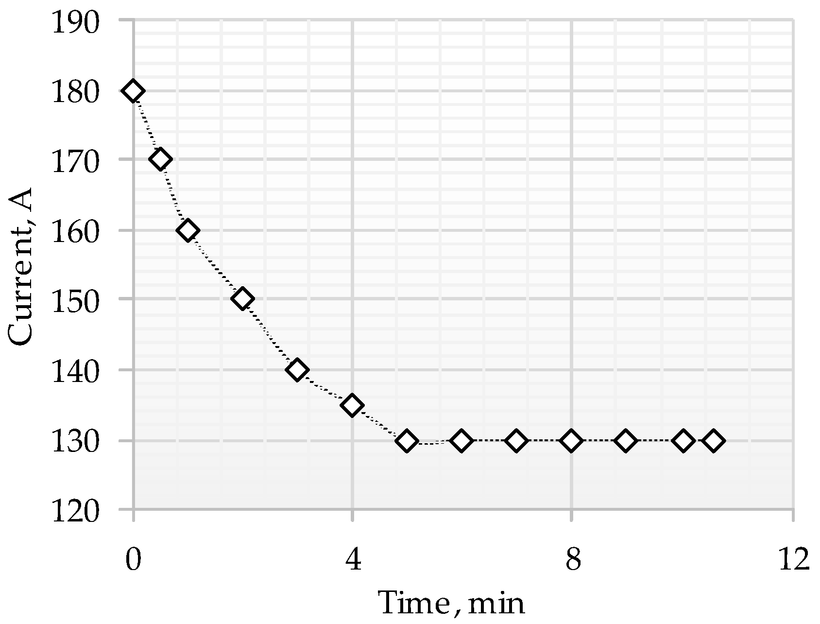
4. Production of Axial-Bearing Washers with Tailored Properties by Plasma Transferred Arc Deposition Welding
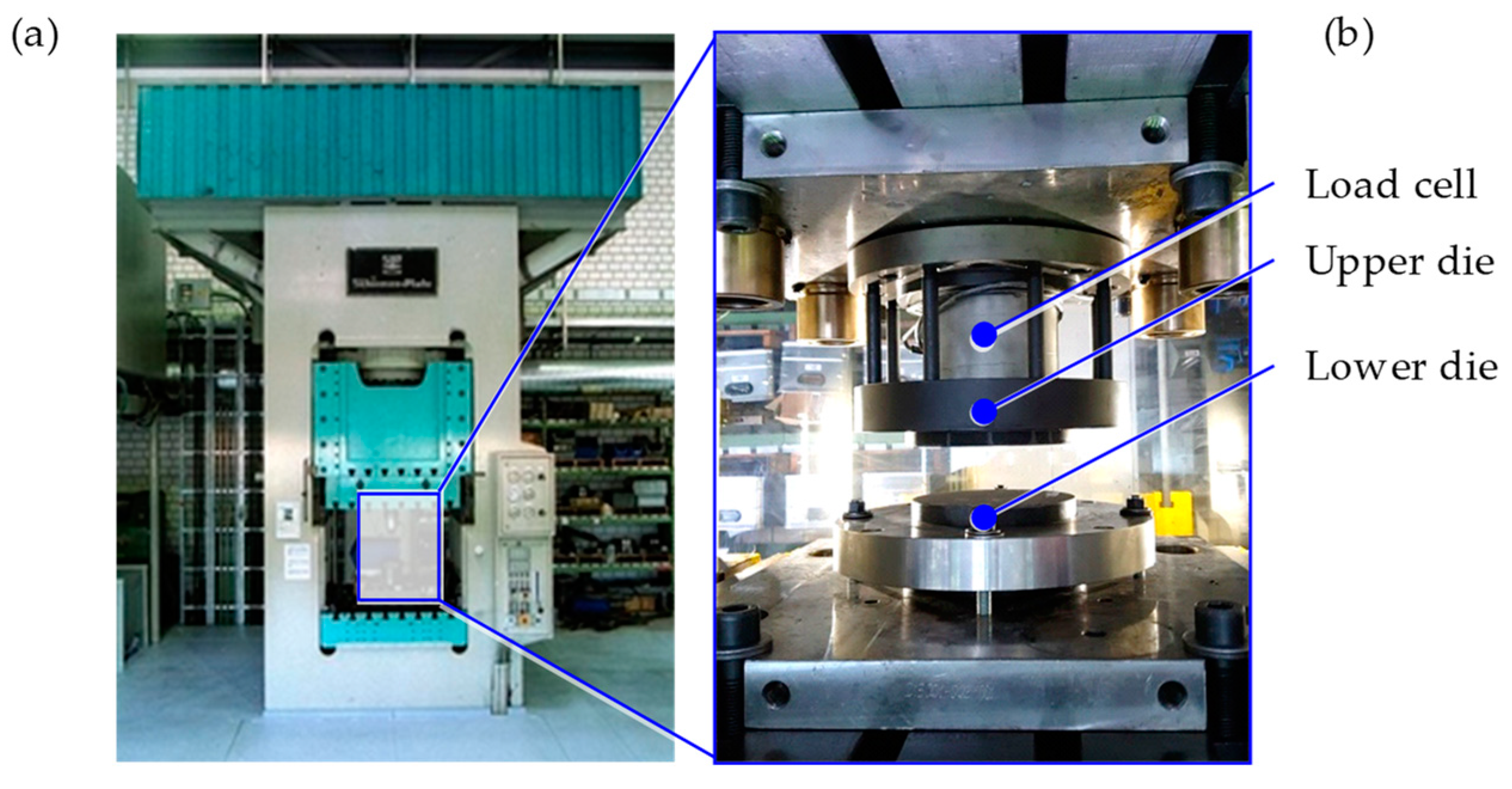
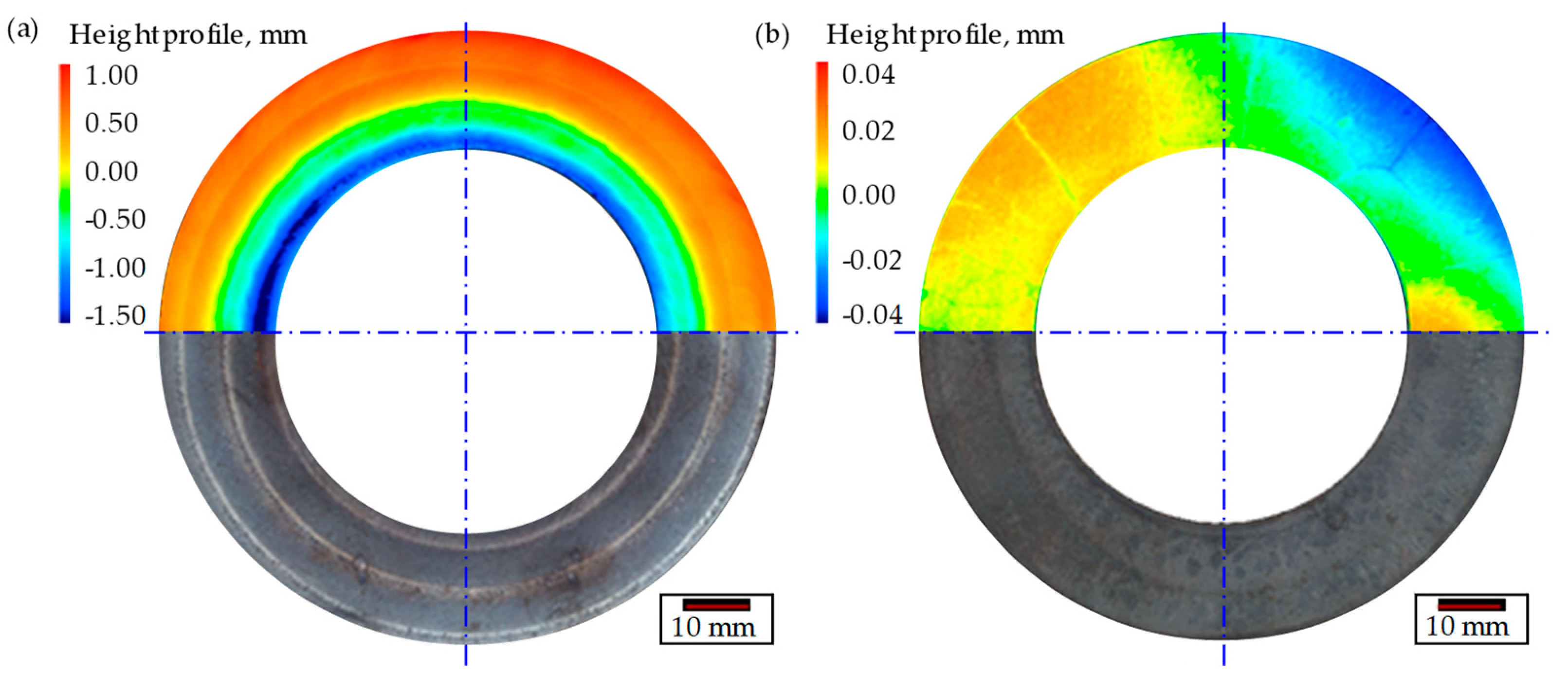
5. Forging of Hybrid Bearing Washers
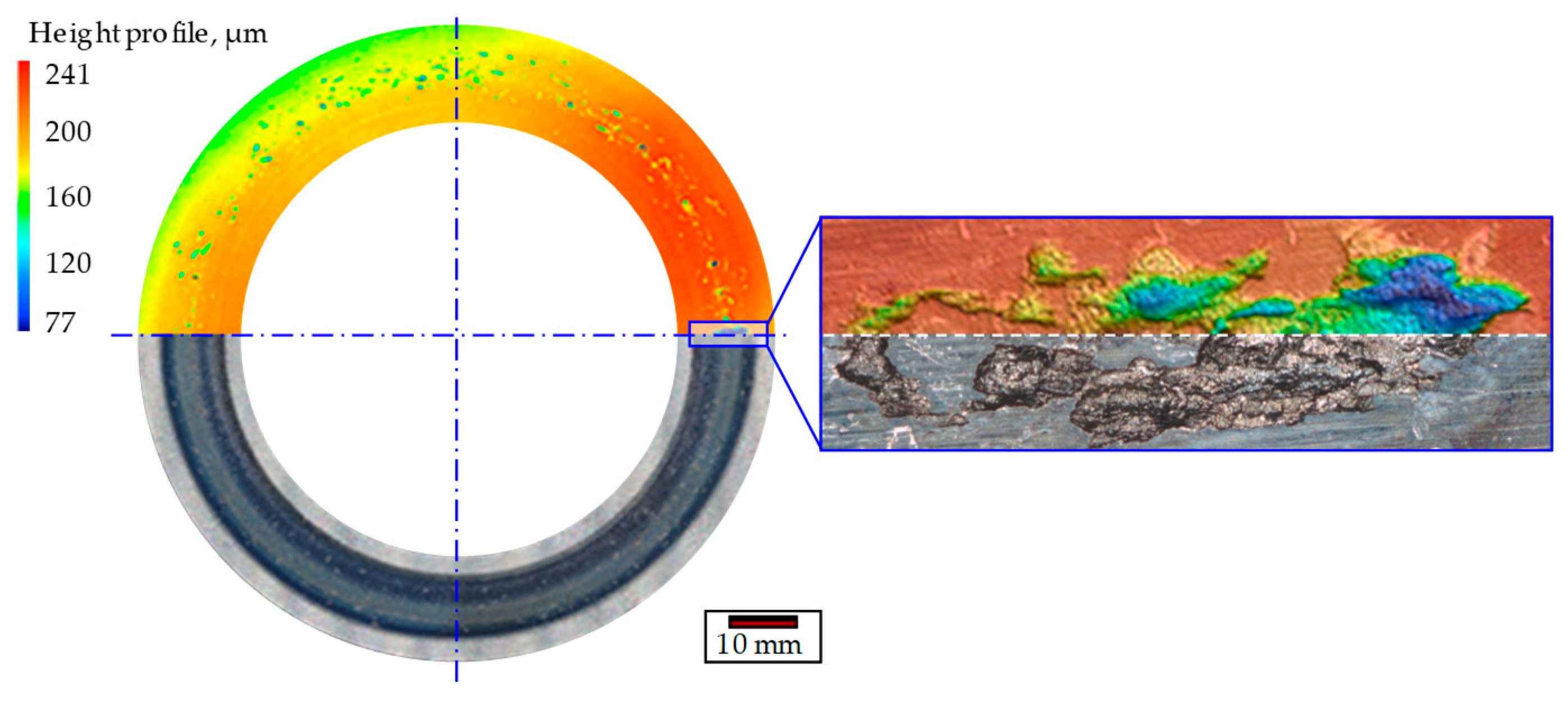
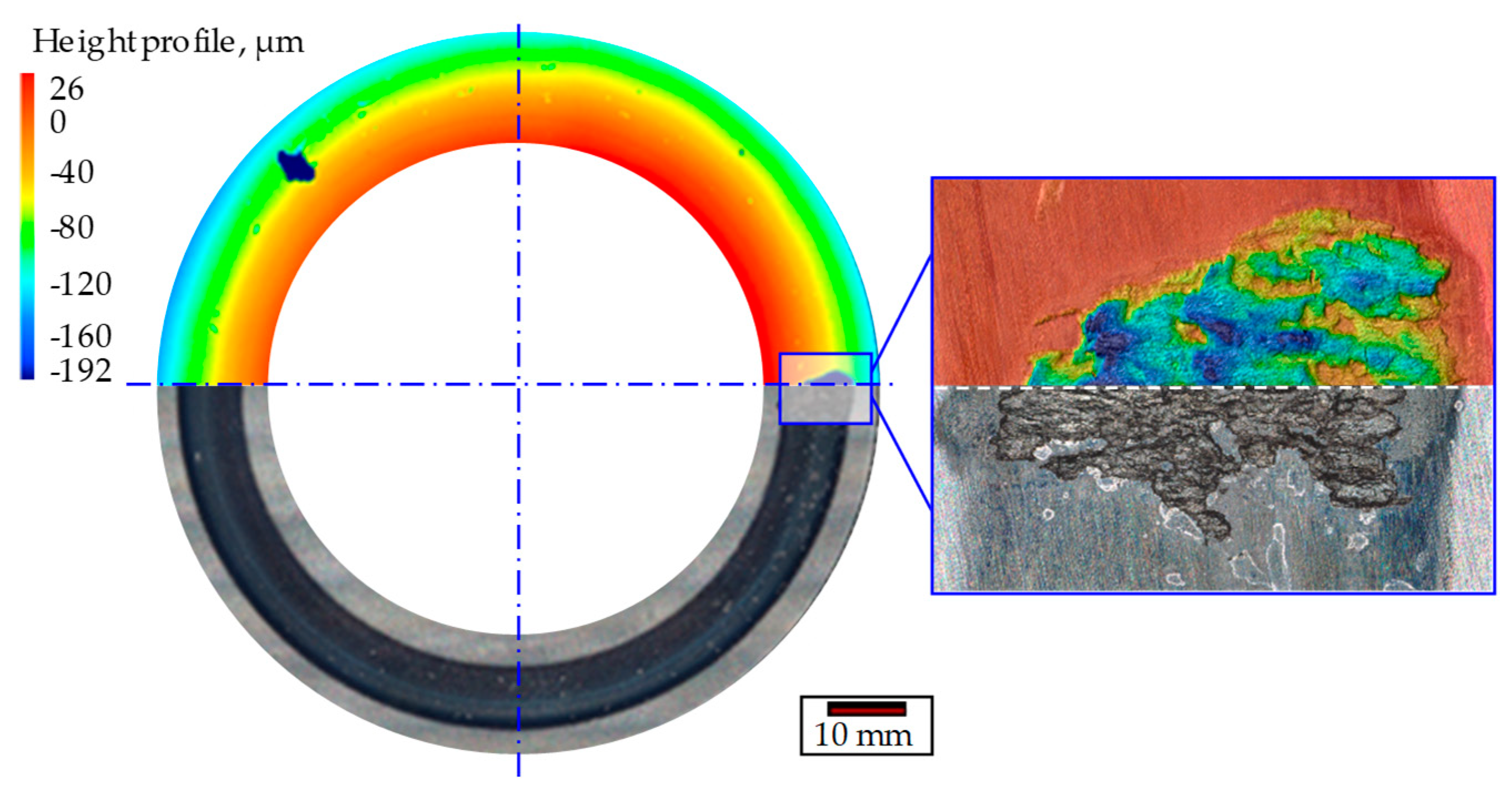
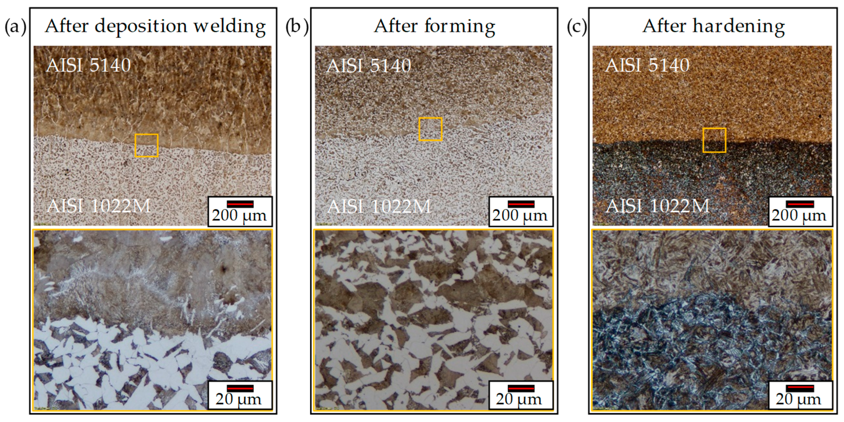
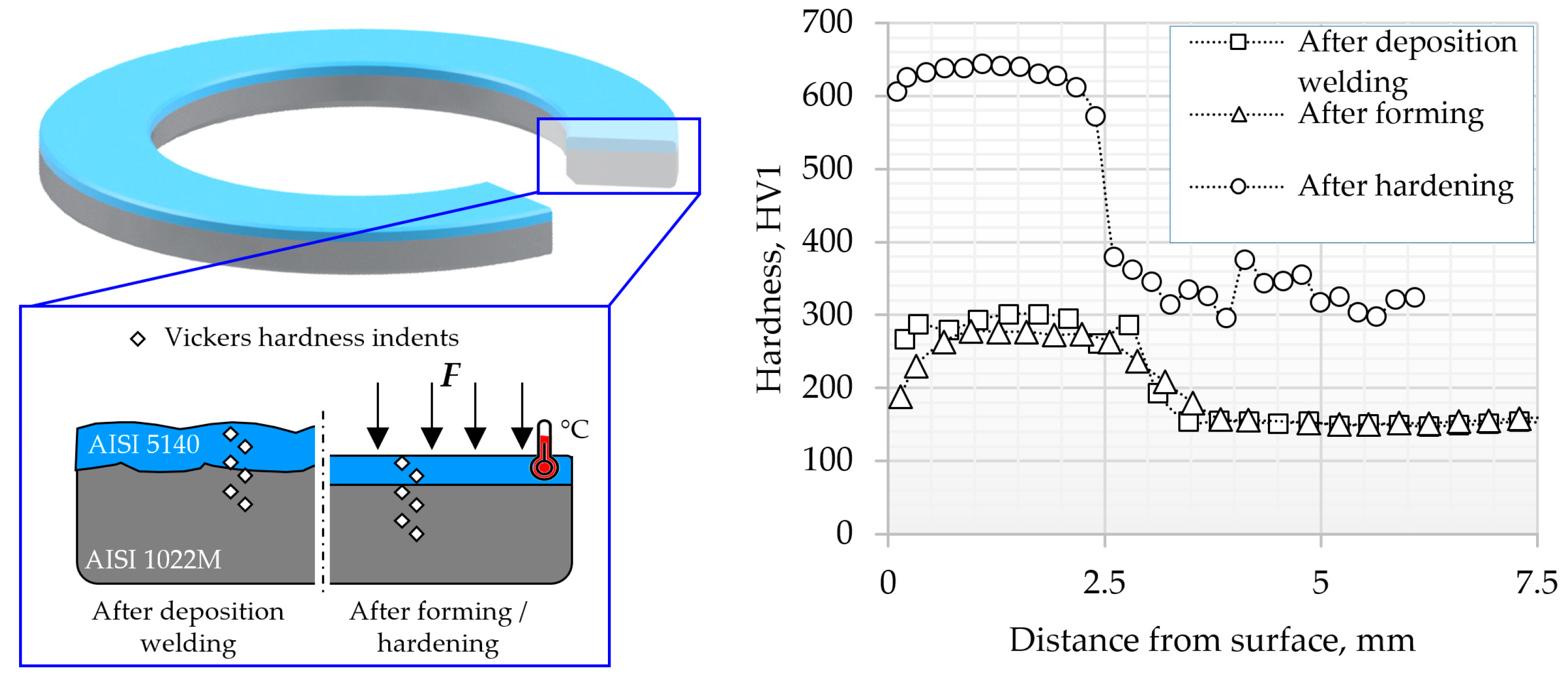
6. Metallographic Investigations
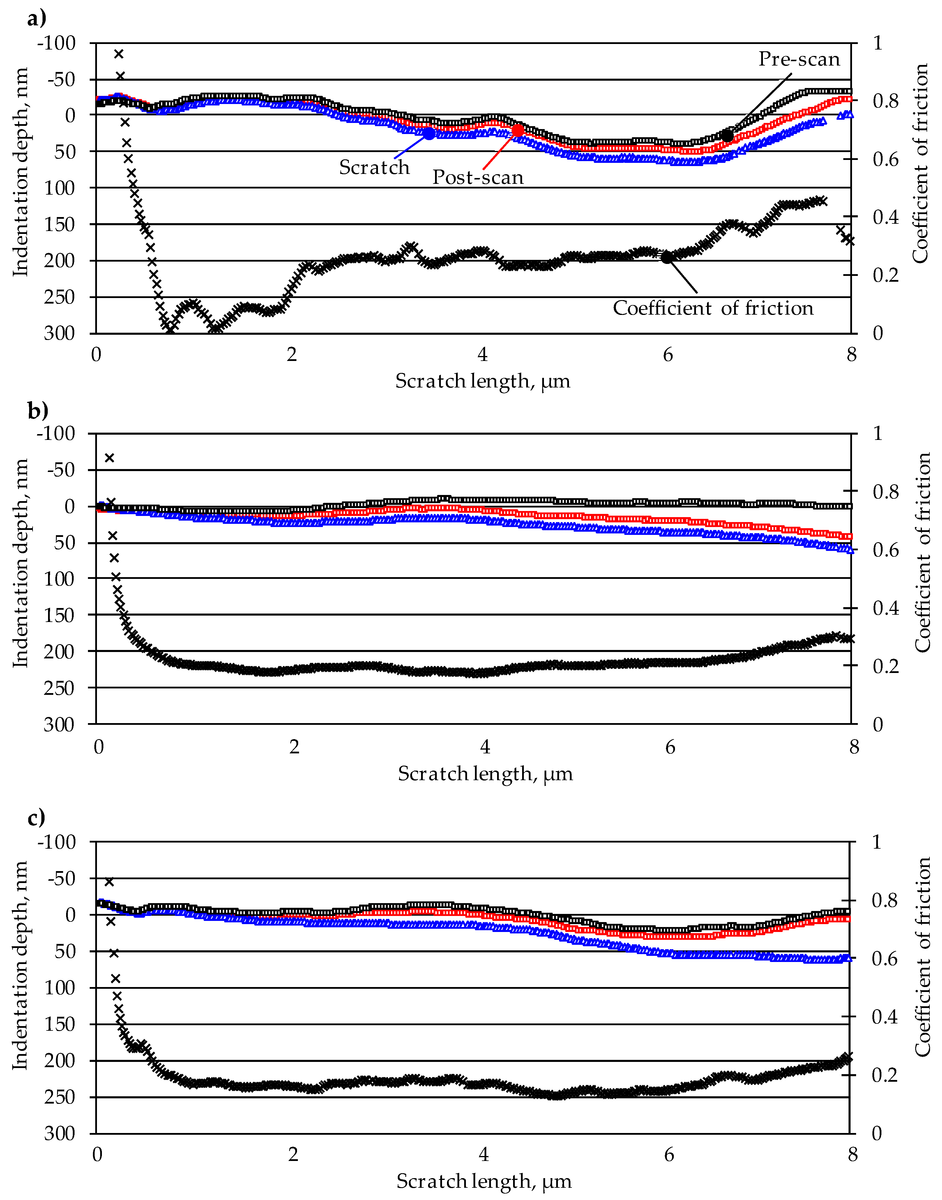
7. Microtribological Investigations
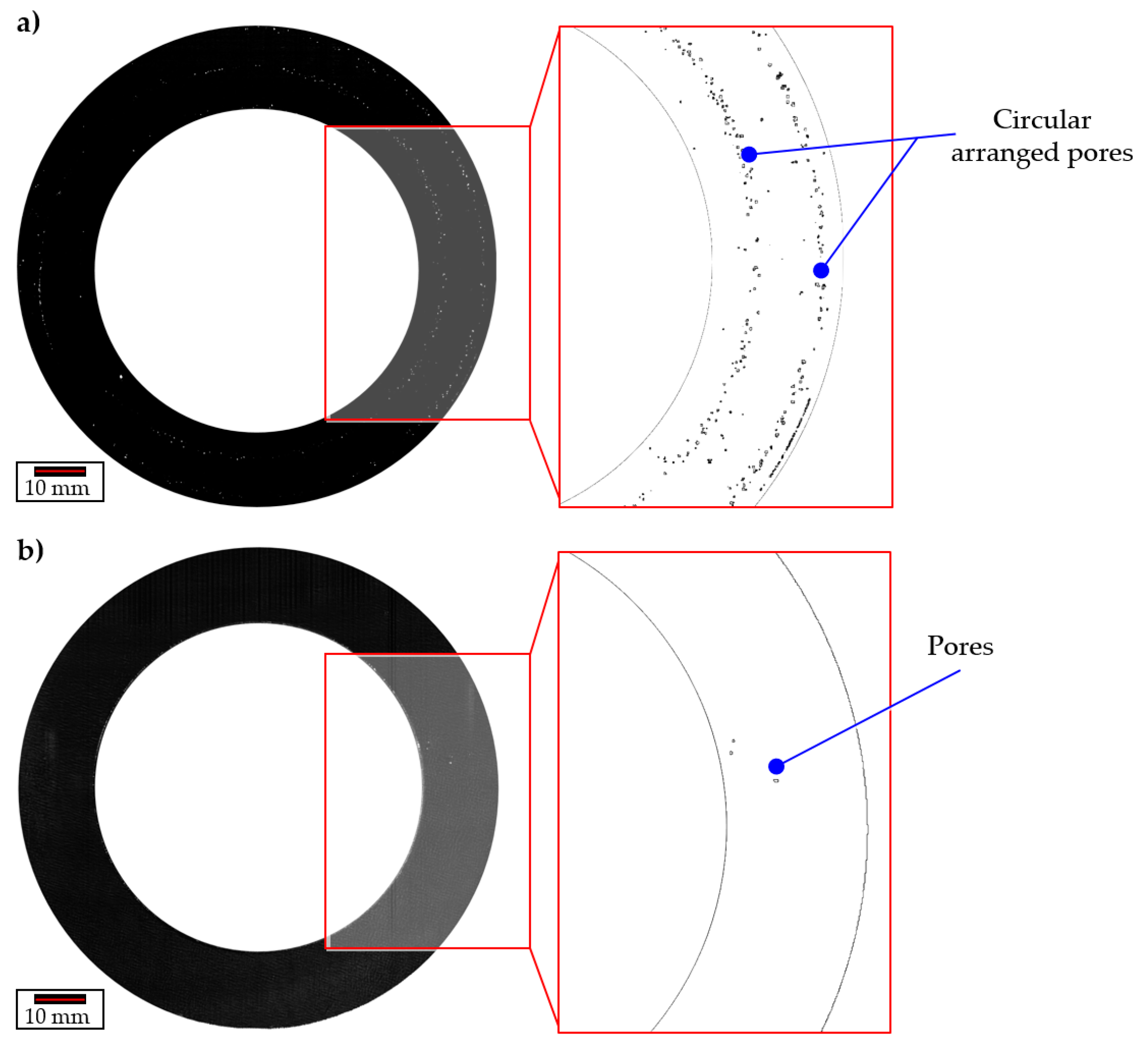
8. Scanning Ultrasonic Microscopy (SAM)
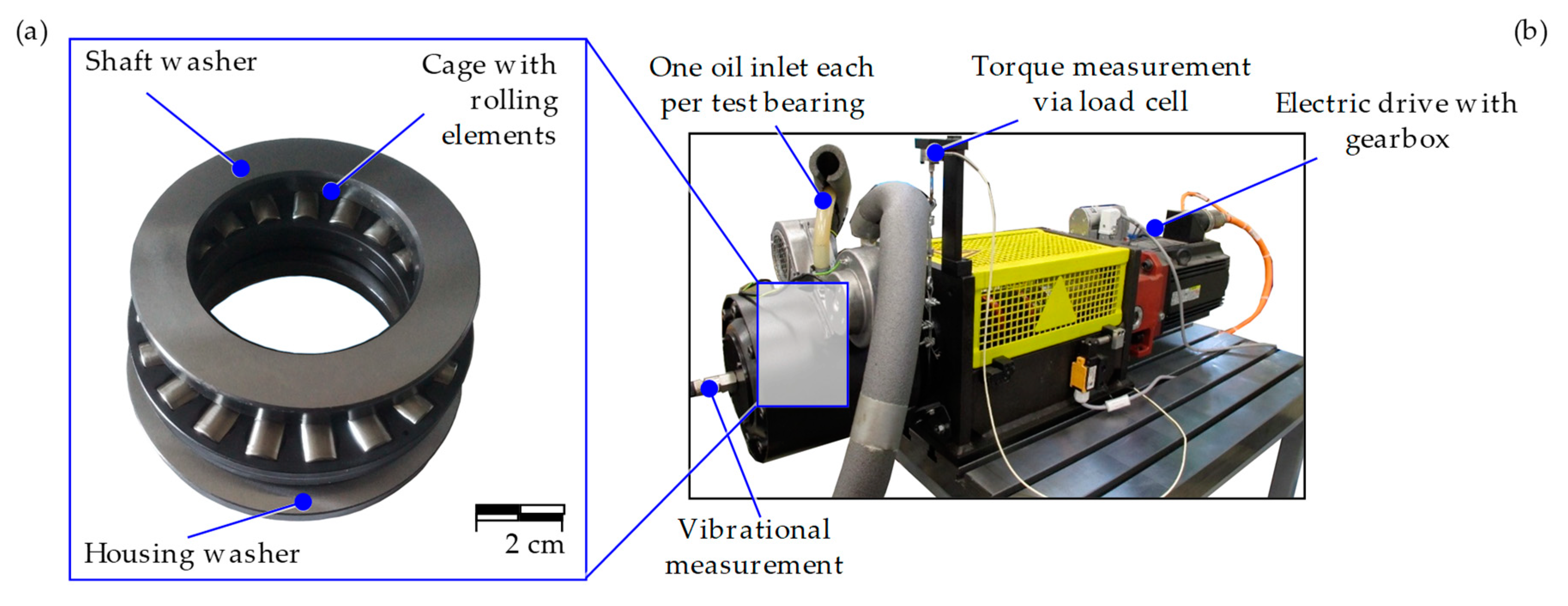
9. Tribological Investigations
10. Conclusion and Outlook
Author Contributions
Funding
Acknowledgments
Conflicts of Interest
References
- Politis, D.J.; Jianguo, L.; Dean, T. Investigation of material flow in forging bi-metal components. In Proceedings of the 14th International Conference on Metal Forming, Krakow, Poland, 16–19 September 2012; pp. 231–234. [Google Scholar]
- Blohm, T.; Mildebrath, M.; Stonis, M.; Langner, J.; Hassel, T.; Behrens, B.-A. Investigation of the cladding thickness of plasma-transferred arc deposition welded and cross wedge rolled hybrid parts. Prod. Eng. 2017, 11, 255–263. [Google Scholar] [CrossRef]
- Mildebrath, M.; Blohm, T.; Hassel, T.; Stonis, M.; Langner, J.; Maier, H.J.; Behrens, B.-A. Influence of cross wedge rolling on the cladding quality of plasma-transferred arc deposition welded hybrid steel parts. Int. J. Emerg. Technol. Adv. Eng. 2017, 7, 1–7. [Google Scholar]
- Mildebrath, M.; Coors, T.; Barroi, A.; Pape, F.; Lammers, M.; Hermsdorf, J.; Overmeyer, L.; Poll, G.; Hassel, T. Herstellungsprozess und wälzfestigkeit von hybriden hochleistungsbauteilen. Konstruktion 2018, 9, 84–89. [Google Scholar]
- Behrens, B.-A.; Bouguecha, A.; Bonk, C.; Bonhage, M.; Chugreeva, A.; Matthias, T. FE-based design of a forging tool system for a hybrid bevel gear. Key Eng. Mater. 2017, 742, 544–551. [Google Scholar] [CrossRef]
- Chugreeva, A.; Bouguecha, A.; Behrens, B.-A. Production Chain of Hot-Forged Hybrid Bevel Gears from Deposition-Welded Blanks. In Proceedings of the 7 WGP-Jahreskongress, Apprimus Verlag, Aachen, Germany, 5–6 October 2017; pp. 21–28. [Google Scholar]
- Pape, F.; Coors, T.; Barroi, A.; Hermsdorf, J.; Kaierle, S.; Matthias, T.; Bonk, C.; Chugreeva, A.; Bouguecha, A.; Mildebrath, M.; et al. Tribological Investigations on Tailored Formed Axial Bearing Washers. In Proceedings of the 6th World Tribology Congress, Beijing, China, 17–22 September 2017; p. 22. [Google Scholar]
- Stanford, M.K.; Jain, V.K. Friction and wear characteristics of hard cladding. Wear 2001, 251, 990–996. [Google Scholar] [CrossRef]
- Ringsberg, J.W.; Skyttebol, A.; Josefson, B.L. Investigation of the rolling contact fatigue resistance of laser cladded twin-disc specimens. Int. J. Fatigue 2005, 27, 702–714. [Google Scholar] [CrossRef]
- Cento, P.; Dareing, D.W. Ceramic materials in hybrid ball bearings. Tribol. Trans. 1999, 42, 707–714. [Google Scholar] [CrossRef]
- Wan, G.T.Y.; Gabelli, A.; Ioannides, E. Increased performance of hybrid bearings with silicon nitride balls. Tribol. Trans. 1997, 40, 701–707. [Google Scholar] [CrossRef]
- Dill, J.F. Hybrid bearing technology for advanced turbomachinery. J. Eng. Gas Turbines Power 1996, 118, 173–178. [Google Scholar] [CrossRef]
- Bach, F.W.; Laarmann, A.; Möhwald, K.; Wenz, T. Moderne Beschichtungsverfahren; Wiley-VCH Verlag GmbH & Co. KGaA: Weinheim, Germany, 2005; pp. 292–305. ISBN 9783527309771. [Google Scholar]
- Torims, T. The application of laser cladding to mechanical component repair, renovation and regeneration. Daaam Int. Sci. Book 2013, 12, 587–608. [Google Scholar]
- Dilthey, U. Schweißtechnische Fertigungsverfahren 2—Verhalten der Werkstoffe beim Schweißen; Springer: Berlin, Germany, 2005; p. 130. ISBN 978-3540216742. [Google Scholar]
- Motallebzadeh, A.; Atar, E.; Cimenoglu, H. Raman spectroscopy characterization of hypo-eutectic CoCrWC alloy tribolayers. Ind. Lubr. Tribol. 2016, 68, 515–520. [Google Scholar] [CrossRef]
- Ferozhkhan, M.M.; Duraiselvam, M.; Ganeshkumar, K.; Ravibharath, R. Plasma transfered arc welding of stellite 6 alloy on stainless steel for wear resistance. Procedia Technol. 2016, 25, 1305–1311. [Google Scholar] [CrossRef]
- Sawant, M.S.; Jain, N.K. Investigations on wear characteristics of Stellite cladding by micro-plasma transferred arc powder deposition process. Wear 2017, 378–379, 155–164. [Google Scholar] [CrossRef]
- Deng, X.; Zhang, G.; Wang, T.; Ren, S.; Bai, Z.; Cao, Q. Investigations on microstructure and wear resistance of Fe-Mo alloy cladding fabricated by plasma transferred arc cladding. Surf. Coat. Technol. 2018, 350, 480–487. [Google Scholar] [CrossRef]
- Behrens, B.-A.; Overmeyer, L.; Barroi, A.; Frischkorn, C.; Hermsdorf, J.; Kaierle, S.; Stonis, M.; Huskic, A. Basic study on the process combination of deposition welding and subsequent hot bulk forming. Prod. Eng. 2013, 7, 585–591. [Google Scholar] [CrossRef]
- Pape, F. Mikrotribologische Untersuchungen an Wälzlagern mit polymeradditiver Fettschmierung; Tewiss Verlag: Hannover, Germany, 2011; ISBN 9783943104158. (In German) [Google Scholar]
- DIN 51819: Mechanisch-dynamische Prüfung auf dem Wälzlagerschmierstoff-Prüfgerät FE8—Teil 3: Verfahren für Schmieröl, Einzusetzende Prüflager, Axialzylinderrollenlager; Beuth Verlag: Berlin, Germany, 2005. (In German)
- Coors, T.; Pape, F.; Poll, G. Bearing Fatigue Life of a Multi-Material Shaft with an Integrated Raceway. In Proceedings of the Bearing World 2018, Kaiserslautern, Germany, 8 March 2018; pp. 23–30. [Google Scholar]


| C | Si | Mn | P | S | Cr |
|---|---|---|---|---|---|
| 0.17–0.24 | <0.40 | 0.40–0.70 | <0.045 | <0.045 | <0.40 |
| C | Si | Mn | P | S | Cr |
|---|---|---|---|---|---|
| 0.38–0.42 | <0.40 | 0.60–0.90 | <0.025 | <0.035 | <0.90–1.20 |
| Parameter | Value |
|---|---|
| Shielding gas flow (Argon) | 10 min−1 |
| Plasma gas flow (Argon) | 1 min−1 |
| Transport gas flow (Argon) | 4 min−1 |
| Welding velocity | 2 mm/s |
| Working Distance | 12 mm |
| Current | Dynamic, 180–130 A |
| Voltage | 25–27 V (depends on current) |
| Powder material | AISI 5140 atomized under argon atmosphere |
| Grid size of powder particles | 0.05–0.15 mm (current industry standard) |
| Powder flow rate | 15 g/min |
| Frequency | Focal Length in Water | Axial Resolution | Detection Limit |
|---|---|---|---|
| 30 MHz | 12.7 mm | 13.68 µm | 6.59 µm |
| 110 MHz | 8 mm | 19.78 µm | 4.56 µm |
© 2019 by the authors. Licensee MDPI, Basel, Switzerland. This article is an open access article distributed under the terms and conditions of the Creative Commons Attribution (CC BY) license (http://creativecommons.org/licenses/by/4.0/).
Share and Cite
Behrens, B.-A.; Chugreev, A.; Matthias, T.; Poll, G.; Pape, F.; Coors, T.; Hassel, T.; Maier, H.J.; Mildebrath, M. Manufacturing and Evaluation of Multi-Material Axial-Bearing Washers by Tailored Forming. Metals 2019, 9, 232. https://doi.org/10.3390/met9020232
Behrens B-A, Chugreev A, Matthias T, Poll G, Pape F, Coors T, Hassel T, Maier HJ, Mildebrath M. Manufacturing and Evaluation of Multi-Material Axial-Bearing Washers by Tailored Forming. Metals. 2019; 9(2):232. https://doi.org/10.3390/met9020232
Chicago/Turabian StyleBehrens, Bernd-Arno, Alexander Chugreev, Tim Matthias, Gerhard Poll, Florian Pape, Timm Coors, Thomas Hassel, Hans Jürgen Maier, and Maximilian Mildebrath. 2019. "Manufacturing and Evaluation of Multi-Material Axial-Bearing Washers by Tailored Forming" Metals 9, no. 2: 232. https://doi.org/10.3390/met9020232
APA StyleBehrens, B.-A., Chugreev, A., Matthias, T., Poll, G., Pape, F., Coors, T., Hassel, T., Maier, H. J., & Mildebrath, M. (2019). Manufacturing and Evaluation of Multi-Material Axial-Bearing Washers by Tailored Forming. Metals, 9(2), 232. https://doi.org/10.3390/met9020232