Article

Direct Correlations among the Grain Size, Texture, and Indentation Behavior of Nanocrystalline Nickel Coatings

1
Tianjin Key Laboratory of Modern Engineering Mechanics, Tianjin 300354, China
2
Department of Mechanics, Tianjin University, Tianjin 300354, China
*
Authors to whom correspondence should be addressed.
Metals 2019, 9(2), 188; https://doi.org/10.3390/met9020188
Submission received: 15 January 2019 / Revised: 28 January 2019 / Accepted: 1 February 2019 / Published: 5 February 2019

Abstract

:
By using nc-Ni coatings as a model system, systematic experiments were designed to evaluate the interaction between the microstructural and mechanical properties tailored by electrodeposition conditions. A direct correlation between grain size and texture was established for the first time. The grain size of the (111) crystalline plane decreases with the texture coefficient (RTC) regardless of the process conditions, and that of the (220) plane has different trends. Then, a peculiar phenomenon is revealed that the dependence of hardness on grain size is accurately described by the Hall-Petch relationship when changing the temperature or pH, but with different slopes, while it deviates from such a relationship with changing current density, denoting more underlying mechanisms related to texture. Finally, a surprising degree of influence of texture on hardness and elastic modulus is also presented, with the overall trend of hardness increasing with texture; and when the RTC of (111) exceeds 40%, the elastic modulus increases with texture, implying a fundamental relationship between modulus and texture. Texture predominates over the other factors on the elastic modulus, revealing the importance of elastic anisotropy. Significantly, the present work suggests a useful tailoring routine to fabricate high quality nc-Ni coatings with the desired structure and mechanical properties.

1. Introduction

Nanocrystalline nickel along with its alloys has been one of the most intensively investigated nanomaterials [1,2,3,4,5,6]. Besides its well-known merits, including environmental friendliness, abundance, and easy synthesis, the tailored architectures of nc-Ni have attracted great interest in the fields of corrosion protection, transportation, energy conservation, catalysis, etc. Such structural features can be tailored by the fabrication process [7,8,9]. Among various coating technologies, electrodeposition (ED) is a low-cost technique suitable for preparing various coatings uniformly with a high rate and efficiency. However, a wide range of deposition parameters need to be selected and optimized to obtain enhanced nanocrystalline characteristics [10,11,12,13]. The fundamental relationship between the microstructure and mechanical properties tailored by fabrication conditions is not fully understood.
The basic structural characteristics include grain size (d) [2], grain boundary (GB) structure [14,15], texture (preferred orientation) [16], defect density [3], etc. The critical mechanical properties mainly include hardness [17,18,19,20], Young’s modulus [9,21], ductility, fracture, and wear [3], etc. Strategies promoting such mechanical properties include tailoring the microstructure of nc-Ni coatings. For example, a refined grain size can improve both the hardness and corrosion resistance of nc-Ni coatings. Matsui et al. [15] reported that hardening can be caused not only by a reduction in the grain size, but also by the GB structure, which is characterized by texture. Godon et al. [18] reported the effects of texture on the Hall-Petch relationship of ED nc-Ni. To date, although several works focused on the interaction between the mechanical properties and microstructural characteristics of nc-Ni, their relationships with fabrication conditions have not been studied. In the present work, we give not only a comprehensive analysis of the direct correlations among the grain size, texture, and indentation behavior of nc-Ni coatings, but also highlight their relationship with fabrication conditions.
During the ED process of Ni coatings, columnar grains commonly form and then induce a fibrous surface texture. Because of the anisotropy of the columnar grain, the grain sizes are believed to be different along different directions, implying that relationships exist between the grain size and texture. As indicated in [12], for Ni-Cu deposits, there is a correlation between the variations of texture and grain size such that a smaller (200) texture coefficient benefits a smaller grain size. Sarac and Baykul [11] concluded that there is a direct correlation between the average crystallite size and the degree of the (111) texture. Savall’s work [21] on nickel coatings also demonstrated that the decrease in grain size is dependent on texture formation in relation with nucleation and growth processes. However, the grain size-texture relationship has rarely been reported. To our knowledge, no research has been dedicated to the quantitative investigation of the direct relationship between grain size and texture and their ability to be tailored by ED parameters, which is one of the goals of the present work. In addition, the relationship between properties and texture is explored. Besides the Hall-Petch relationship linking hardness and grain size, the direct relationship between hardness and texture is also revealed. Furthermore, the fundamental relationship between modulus and texture is disclosed for the first time.
In this context, by using nc-Ni coatings as our model system, we designed systematic experiments to achieve the successful production of coatings with different microstructures on mild steel substrates using six current densities, four bath temperatures, and four electrolyte pH values for ED using a modified Watts bath. Details of the structural and mechanical quantitative variations, which are not common and are often ignored in this field, are disclosed. The present work provides useful guidance for the fabrication of high-quality nc-Ni coatings with desired structures and properties.

2. Experimental

2.1. Materials and Solutions

Nickel coatings were prepared by galvanostatic deposition. A conventional modified Watts-type bath was used, and it contained 240 g/L NiSO4·6H2O, 20 g/L NiCl2·6H2O, and 20 g/L H3BO3. The electrolyte was prepared from analytical grade chemicals and distilled water. All experimental chemicals were provided by Tianjin Guangfu Fine Chemicals Research Center, China, and employed without further refinement. Q235A mild steel was used as the substrates with dimensions of 20 mm × 10 mm × 3 mm.

2.2. Pretreatment of Substrates

The main treatment processes were as follows: Sanding polishing chemical de-oiling electrochemical deoiling. First, the specimens were sanded with corundum grinding wheels, numbers 60 and 80. Then, they were polished by sponge wheels, numbers 300 and 800. The next step was chemical de-oiling, followed by electrical de-oiling. The chemical composition and content of the solution used for chemical de-oiling was composed of 65 g/L NaOH, 17.5 g/L Na2CO3, 17.5 g/L Na3PO4H2O, and 5.0 g/L Na2SiO3H2O. In this test, the specimens were put into the solution at 70 °C for 2 min. Then, electrochemical de-oiling was carried out in a solution containing 15 g/L NaOH, 55 g/L Na2CO3, 35 g/L Na3PO4·H2O, and 7.5 g/L Na2SiO3H2O for 1 min. The current was 0.2 A, with a solution temperature of 70 °C. Finally, the steel substrates were activated in a 10% HCl solution at room temperature for 10 s and then rinsed with distilled water.

2.3. Electrodeposition

For electrodeposition, the Q235A mild steel substrate as described above was used as the working electrode. For better reproducibility, all electrodeposition tests were performed under the same conditions. The electrolyte for the deposition was prepared in two steps. First, NiSO4H2O and NiCl2H2O were added into 500 mL distilled water and then stirred continuously at 50 °C to ensure a uniform distribution of the chemical compositions. Second, 200 mL distilled water was mixed with H3BO3 and heated to 90 °C to dissolve H3BO3. Finally, the plating solution was obtained by mixing the above two solutions and cooling it to room temperature. The plating bath was equipped with a Smart Temperature Control Magnetic Agitator, model number DF-101S, to maintain constant bath temperature during experiments, and agitated by a magnetic stirrer at 150 rpm.
In ED plating, the microstructure and mechanical properties of the resulting deposits depend on process conditions. We focused on three key process parameters, namely, current density, bath temperature, and electrolyte pH. So, three groups of experiments (12 series, considering samples 2, 8, and 12 are identical) were performed with the operating conditions and parameters listed in Table 1.

2.4. Electrochemical Testing and Structural Characterization

Electrochemical testing was carried out with an electrochemical workstation CHI660E (Beijing Huake Putian Technology Co. Ltd., China) in a three-electrode cell system. The substrate to be electrodeposited was used as a working electrode. The counter electrode was a platinum plate, and a saturated calomel electrode (SCE) placed in a separate fritted glass tube was used as the quasi-reference electrode. The cathode polarization tests were conducted in the plating solutions.
Several techniques were adopted to investigate the microstructure and properties of nickel coatings. The X-ray diffraction (XRD) patterns were recorded by a BDX 3300 diffractometer using Cu Kα radiation (λ = 0.15418 nm). The relative intensity was measured with a 2θ range of 10–90° at a scanning rate of 4°·min−1. The morphology was analyzed using a field emission scanning electron microscope (FESEM, JEOL, JSM-6700). Cross-sectional samples, prepared by metallographic cutting, were embedded in room temperature-setting epoxy resin, ground, and polished [22]. Then, they were etched for approximately 8 s with a solution of 50 mL concentrated acetic acid (C2H4O2) and 50 mL concentrated nitric acid (HNO3) [23]. The microstructure of the nickel coatings was also examined by transmission electron microscopy (TEM, Tecnai G2F20 S-Twin) operated at 200 kV, and grain size distribution was determined using nano-measurement software on the TEM bright-field images. Thin foil TEM specimens with a diameter of 3 mm were fabricated by mechanical polishing and Ar ion milling.
The hardness and elastic modulus were evaluated by a Nano indenter (MTS NanoIndenter XP, USA) with a diamond Berkovich indenter tip. The maximum indentation depth was kept at approximately 1–1.3 μm for 10 s (no more than 10% of each coating thickness) to eliminate the substrate effect, and six indents on different areas for each specimen were performed to obtain reliable statistics.
The hardness and elastic modulus of coatings can be evaluated by the nanoindentation test from the load-displacement curves using the standard analysis procedure proposed by Oliver and Pharr [24]. Hardness (H) was calculated from:
  H = P m a x A
where P m a x is the maximum load applied during nanoindentation and A is the contact area.
The contact stiffness, S, of the sample can be obtained from the slope of the beginning of the unload curve. Then, the reduced elastic modulus, Er, was evaluated [25]:
S = β 2 π E r A
where β is a dimensionless parameter that depends on the geometry of the indenter, which is 1.034 for a Berkovich indenter.
The Young’s modulus of the coating, E, can then be determined as:
1 E r = 1 γ 2 E + 1 γ i 2 E i
where, E and γ are the Young’s modulus and Poisson’s ratio, respectively, for the sample and E i and γ i are the corresponding parameters for the indenter. In this study, we take γ i = 0.07 and E i = 1141   GPa [25].
XRD was employed to determine the grain sizes and texture of nc-Ni electrodeposits. The crystallite size was calculated using Scherrer’s equation [16]:
FWHM = K λ d   c o s θ 180 π
where FWHM is the full width at half maximum in 2 θ degrees, d is the crystallite size in nm, and K and λ take the values of 0.94 and 0.154 nm, respectively.
To describe the structure and quantitatively determine the preferred orientation of deposits, the relative texture coefficient, R T C ( h k l ) , was calculated by [16]:
R T C ( h k l ) = I ( h k l ) / I ( h k l ) 0 1 n I ( h k l ) / I ( h k l ) 0 × 100 %
where I ( h k l ) are diffraction intensities of the ( h k l ) lines determined by the diffractogram of deposits and I ( h k l ) 0 are the corresponding intensities of a standard Ni sample randomly orientated from JCPDS 04-0850.

3. Results and Discussion

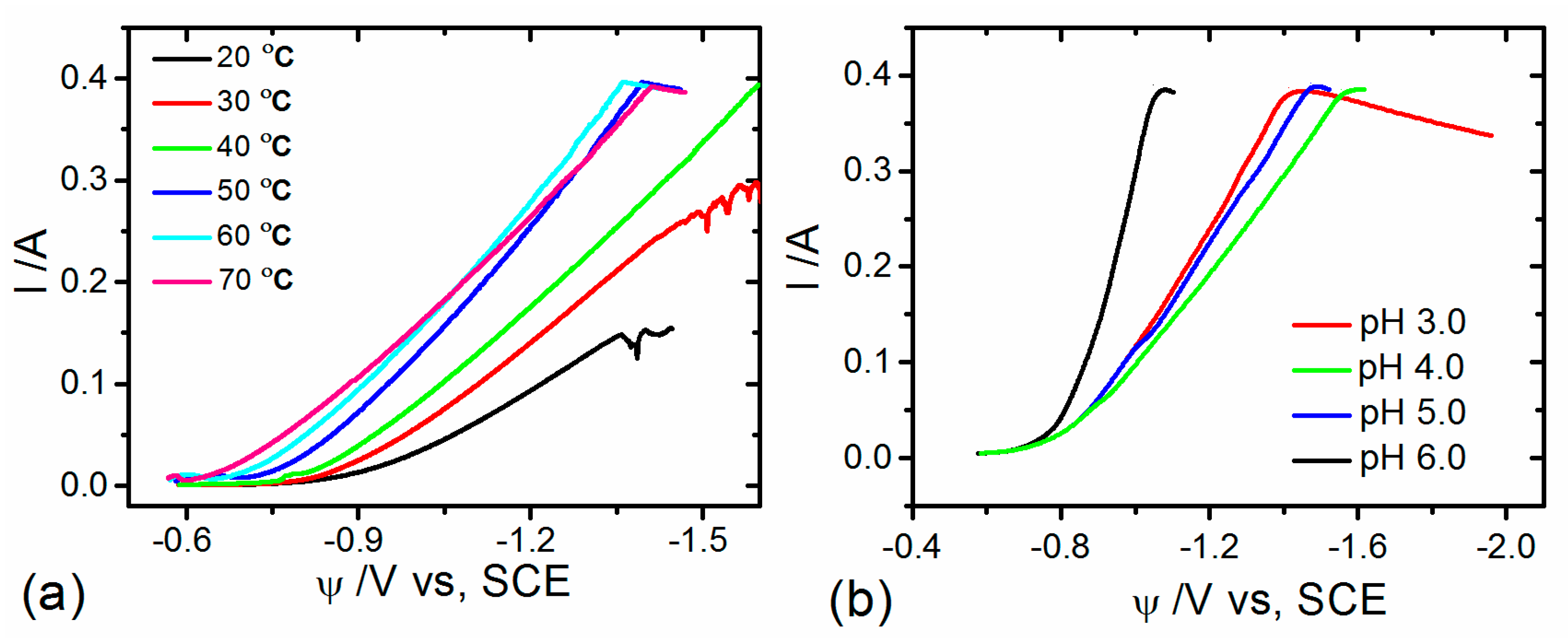
3.1. Voltametric Behavior

In electrodeposition, it is important to consider the electrochemical behavior of metal ions. In this section, the reduction process of Ni2+ on Q235A mild steel substrates was examined by the linear sweep voltametry method. Cathodic polarization curves were constructed to study the effects of bath temperature and electrolyte pH on the cathode. According to these results, we can determine the suitable range for these process parameters.
Figure 1a shows the cathodic polarization curves at different temperatures. It is apparent that the influence of temperatures on nickel deposition is significant. The decrease of bath temperature produces an inhibition of the Ni deposition current. When potentials were in the range of 0.57   V ~ 0.70   V , the deposition current was small at different temperatures, while as the potential was more negative than −0.70 V, the deposition current became larger and increased with increasing temperature. This denotes that the decrease of temperature increases polarization and inhibits the deposition of Ni2+. However, when the temperature exceeded 60 °C, water vapor evaporation was accelerated, and the electrolyte became unstable and unfavorable for deposition. Normally, the temperature of electrodeposition is chosen in the range of 25–55 °C [11]. According to these results, the range of temperature in the present study was set in the range of 40 to 60 °C.
Figure 1b shows the cathodic polarization curves at different pH values. When the pH value increased from 3.0 to 4.0, the polarization of the cathode was increased, and the current density decreased, suggesting that the overpotential for the nickel deposition was increased. When the pH level increased to 5.0, a slight shifting of the cathodic current peak towards a less negative potential than that of pH 4.0 indicates a decrease in polarization. However, when the pH value increased to 6.0, the cathodic polarization decreased substantially to promote the nickel deposition with the expectation of more rough and loose deposits. Based on these results, we chose the pH values in the range of 3.5~5.0 for our electrodeposition experiments as shown in Table 1.

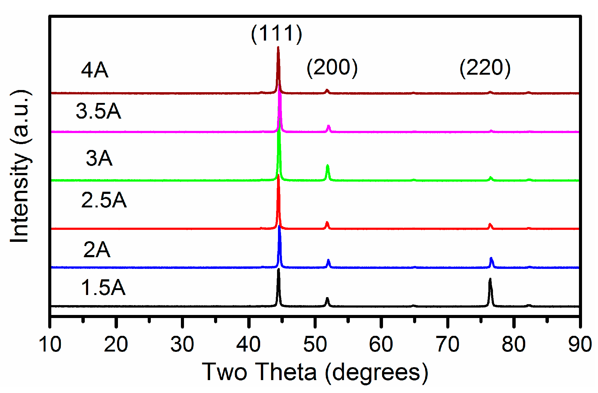
3.2. Effects of Current Densities on Morphology and Microstructure

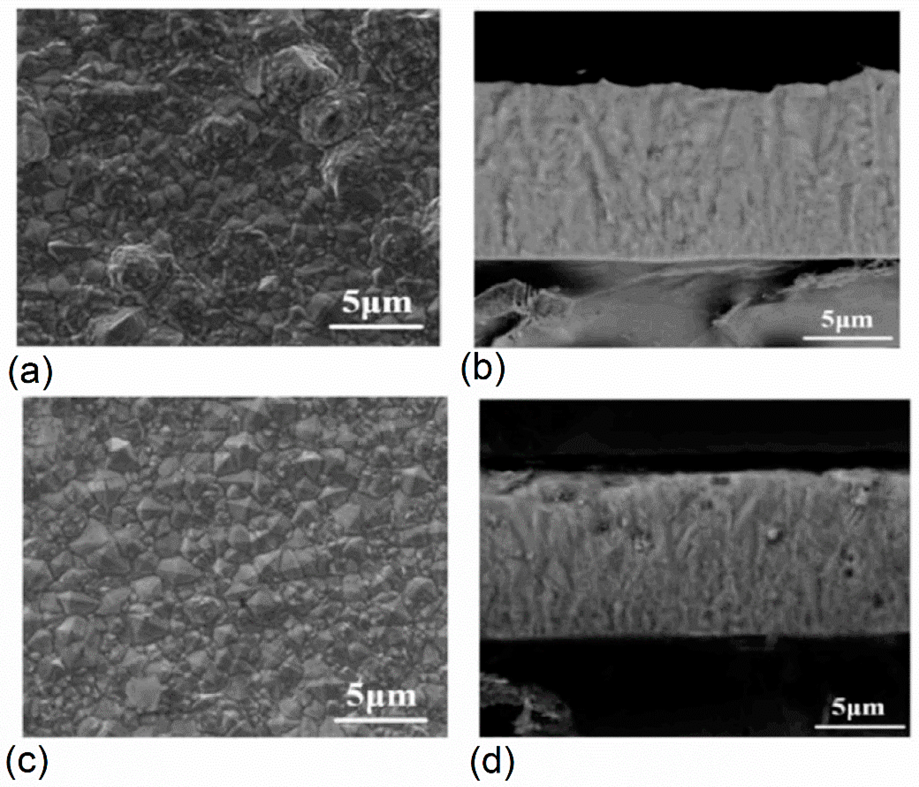
3.2.1. Morphological Characterization

The surface images of Ni coatings deposited at different current densities are presented in Figure 2. The nickel coatings have similar surface appearances, but the shape of the coatings changes with increasing current density. All the morphologies show a mixed structure of truncated pyramids and cauliflower shapes. Figure 2a shows the surface of coatings deposited at the current density of 1.5 A·dm−2 with more pronounced cauliflower-like structures and deep crevices outlining groups of smaller substructures that are visible over the entire surface. However, when the current density increases, the coating surface becomes more compact and smoother. The microcrevices between different grains gradually disappear as indicated by Figure 2c, and the grains are separated by clear boundaries. Contrary to other works, we chose the current densities in a narrow range, from 1.5 A·dm−2 to 4.0 A·dm−2, to examine their subtle effects on the microstructure and mechanical properties.
Figure 2b,d show the cross-sectional SEM images (backscattered electron mode) of Ni coatings deposited at the current densities of 1.5 and 3.5 A·dm−2. Cross-section observations of both coatings after chemical etching exhibit the formation of long columnar grains, parallel to the growth direction, with a width of a few micrometers. In both images, the blanket films are still attached to the substrates, and these films appear as somewhat finer-grained regions at the substrate interface with some non-uniformity and cavity structures. The microstructure of the deposits at the interface is initially equiaxial, but with continued growth, it rapidly evolves into columnar structures. This result agrees with that obtained by Godon et al. [26] and Bund et al. [23]. The thickness of the coating was uniform with an average value in the range of 14~16 μm based on more than six profile measurements at different positions.

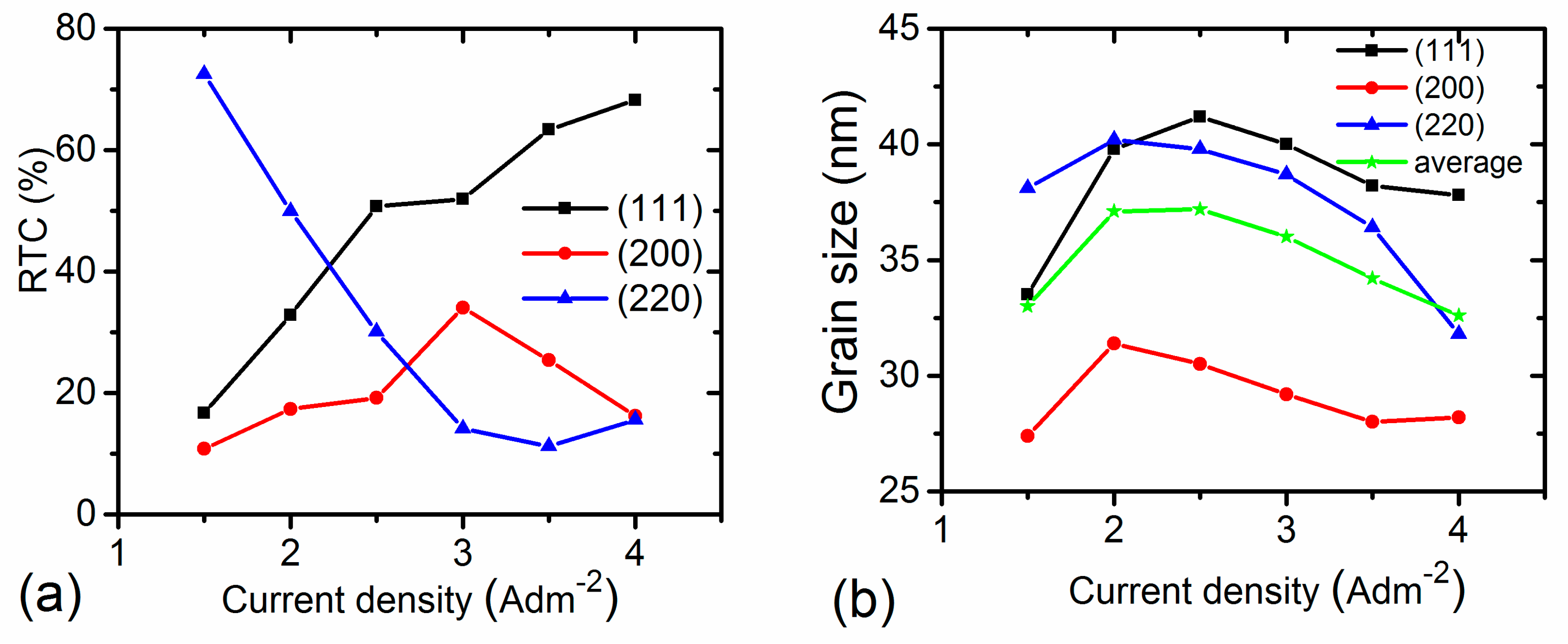
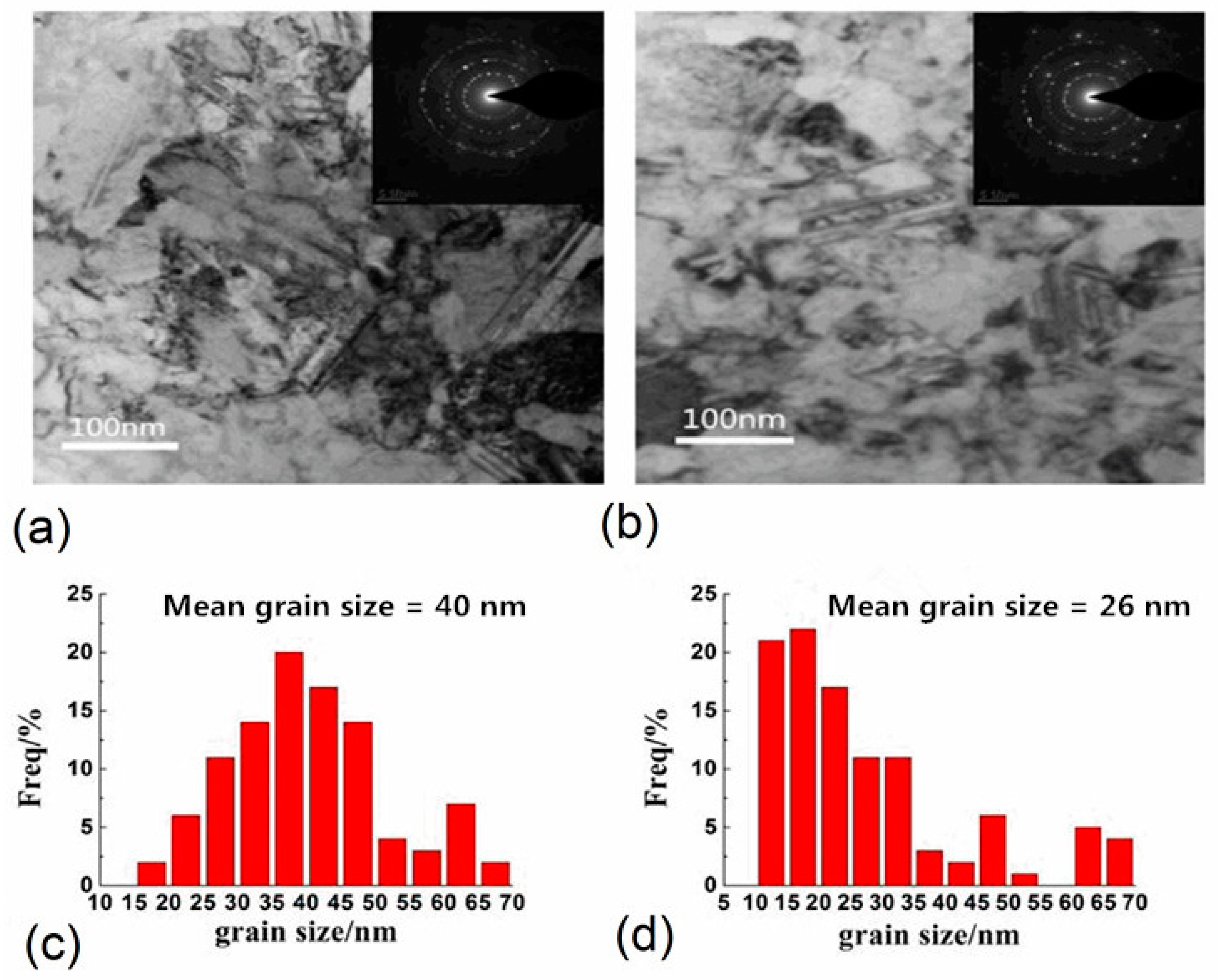
3.2.2. Structure Properties

Details of the grain size and texture evolution of nc-Ni coatings were examined using XRD analysis. Figure 3 shows the XRD pattern of deposits plated at different current densities, revealing that all deposits display three main Bragg diffraction peaks indexed as the (111), (200), and (220) planes of the face-centered cubic (FCC) crystal structure. By comparing the XRD spectra, an apparent change in the crystallographic structure according to the intensities of the (111) and (220) diffraction peaks is observed. This result means that the current density plays a critical role in controlling the Ni (111) and (220) peak intensities. In contrast, the intensity of the Ni (200) peak shows little change. This phenomenon implies that the crystallographic orientation was not randomly orientated, but grains grew in specific orientations and were significantly influenced by current density.
The relationship between the current density and the R T C ( h k l ) is described in Figure 4a. We can see that the preferred orientation is the (220) crystalline plane at the lowest current density of 1.5 A·dm−2, as indicated by the intensive (220) line and a high value of R T C ( 220 ) . Nevertheless, the increase in current density leads to a decrease in the strong (220) texture, owing to the enhancement of the (111) crystalline plane. Grain size calculated from the Scherrer equation shows that grain refinement is observed with an increase in current density. We compared the changes in the grain size of different crystalline planes, as shown in Figure 4b. The figure shows that the grain size of the (111) and (220) crystalline planes first increases and then decreases gradually with a further increase in current density. Variations in the current density have little influence on the grain size of the (200) crystalline plane. Average grain sizes obtained from the (111), (200), and (220) peaks for each nc-Ni coating are also examined as described in Figure 4b.
The Ni coating was further investigated by TEM. Figure 5 shows TEM bright-field images, the corresponding selected area diffraction (SAD) patterns, and the grain size distribution of coatings deposited at the current densities of 2.0 A·dm−2 and 4.0 A·dm−2. Both Ni coatings are composed of uneven grains. Some larger grains are divided into two or more smaller grains, and a number of nanoscale twins are also observed. The grain size distributions determined from TEM bright-field images with average grain sizes of 40 nm at 2.0 A·dm−2 current density and 26 nm at 4.0 A·dm−2 current density are shown in Figure 5b and d. Therefore, the latter displays a somewhat finer grain size than that of the former, which agrees with the SEM results above. However, there are some slight deviations between the results from XRD and TEM, similar to the results reported in [14,15]. Figure 5 also shows typical electron diffraction patterns. Three sharp rings, corresponding to (111), (200), and (220) of the Ni, confirmed the Ni nanocrystalline coating with an FCC structure, which is consistent with the XRD results.

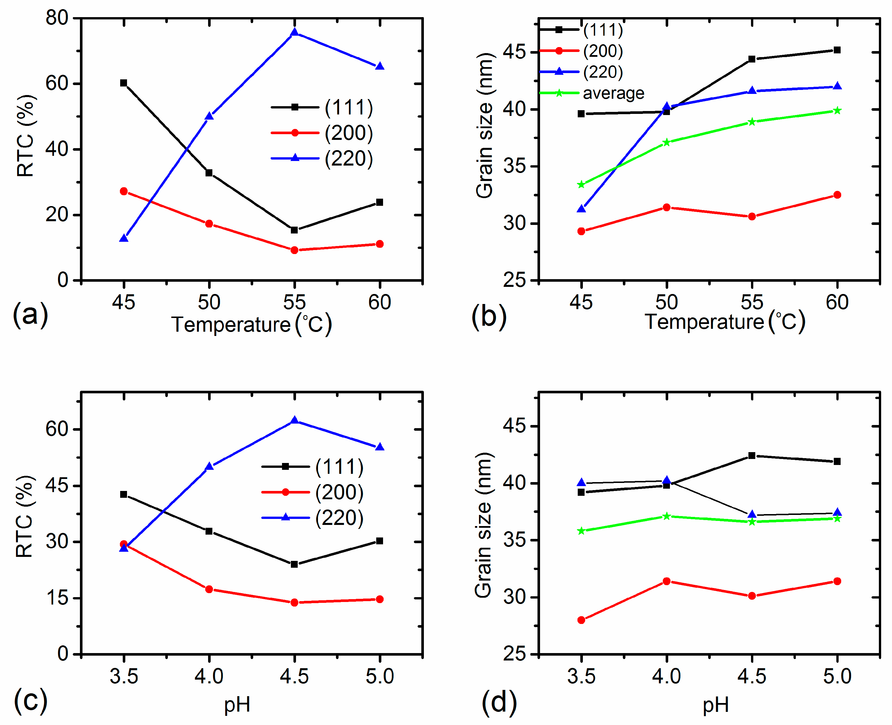
3.3. Effects of Temperature and pH Value on Morphology and Microstructure

In this section, we focused on the role of bath temperature and pH value on the surface morphology and crystallographic structure of nc-Ni coatings. The influence of bath temperature and pH value on the surface morphology was examined by SEM, but is not presented here. All films displayed pyramid-like grains with different sizes, featuring cauliflower-like clusters in some regions, and the surface morphology was considerably influenced by bath temperature and pH value.
The structure properties of the coatings were explored by XRD analyses (not displayed here). All films showed face-centered cubic (FCC) structures with different widths of the FCC reflections across various samples. The RTCs of the (111), (200), and (220) peaks as a function of electrolyte temperatures and pH values are shown in Figure 6a,c. The variations in temperature have noticeable effects on the texture evolution along different orientations. At a temperature of 45 °C, the nickel film has a (111) preferred orientation, but with increasing electrolyte temperature, RTC(111) decreases continuously, while the (220) texture becomes dominant until the temperature reaches 55 °C. Further increasing of the bath temperature leads to a decrease of the (220) texture and increase of the (111) texture. Accordingly, a rise in electrolyte temperature seems to weaken the degree of the (111) texture and enhance the (220) texture, which is consistent with former investigations [11].
The values of grain size from the (111), (200), and (220) peaks and the average grain size as a function of the bath temperatures are illustrated in Figure 6b. The grain sizes of the deposits were found to be in the range of 29.2 = 3 ± 2–45.2 ± 2 nm, which indicates a nanocrystalline structure. For the (200) crystalline plane, there is no apparent difference in grain size between each temperature. By contrast, the largest increase in grain size occurs in the grain of the (220) crystalline plane when the temperature rises from 45 °C to 60 °C, while the average grain size and the grain size of the (111) crystalline plane rise gradually with an increasing temperature. In summary, the overall trend is that the grain size of deposits increases with increasing bath temperature. The complicated phenomena can be interpreted that, as shown in Figure 1a, the cathodic overpotential increases towards more positive values with increasing electrolyte temperature, and a higher cathodic overpotential decreases the energy of the nucleus formation, leading to an increase in the nucleus densities and a decrease in the crystallite size.
Next, we examined the effect of the pH value. At a pH of 3.5, RTC(111) is about 42.6%, while both RTC(220) and RTC(200) are approximately 28%; this implies that the preferred orientation is the (111) crystalline plane. With increasing pH levels, RTC(111) decreases, while RTC(220) increases slowly and becomes dominant. This illustrates that the texture of the coatings varies gradually from the (111) plane to the (220) plane with the increase in pH values. Boubatra el al. [13] reported the formation of FCC-structured Ni thin films with a preferred orientation along the Ni (111) at various electrolyte pH values. The crystallite sizes of the (111), (200), and (220) crystalline planes, together with the average grain size, are exhibited in Figure 6d. It is shown that the pH has little influence on grain size. This result also denotes that, compared to current density and bath temperature, the electrolyte pH has only a minor effect on the grain size.
It is generally acknowledged that there are a set of chemical reactions assumed to be more relevant to nickel deposition. The related reactions can be expressed as follows [27,28]:
2 H 2 O + 2 e H 2 + 2 OH
Ni 2 + + OH NiOH +
NiOH + ( NiOH ) ads +
( NiOH ) ads + + 2 e Ni + OH
The changes in the surface morphology and microstructure of nc-Ni films may be attributed to the formation of different interfacial inhibitors, such as H2, Hads, or Ni(OH)2, during the electrodeposition process. Inhibitory nickel hydroxide is formed by the above reactions; H2 and Hads are produced by the hydrogen evolution reaction (HER), which proceeds simultaneously and depends on pH levels. It is generally assumed that there are two reactions for HER during the electrodeposition of nickel coatings from aqueous solution, which can be described as [27]:
Ni + H + + e Ni H ads
2 Ni H ads 2 Ni + H 2   or   Ni H ads + H + + e Ni + H 2
The hydrogen reaction may change the electrochemical conditions near the cathode, leading to the formation of different crystalline structures. The texture degrees of electrodeposited coatings may change due to the presence of these inhibiting species.

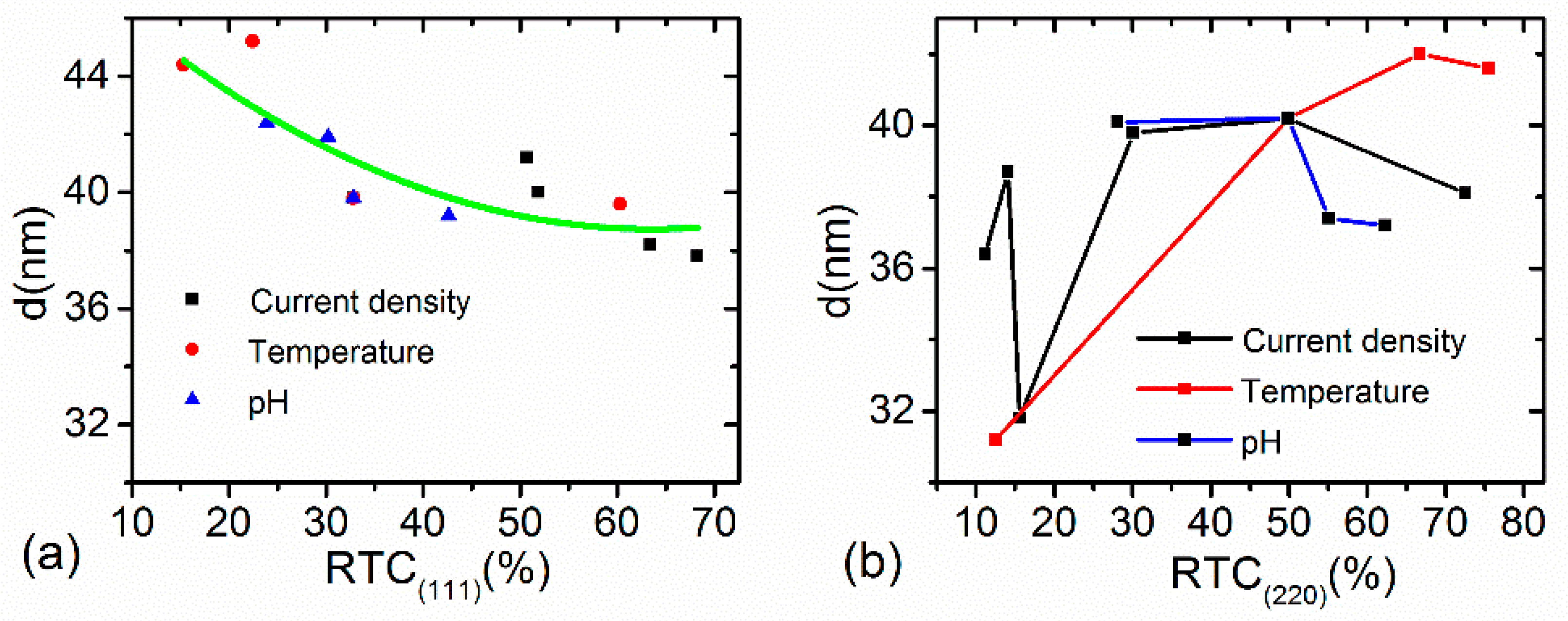
3.4. Relationship between Grain Size and Texture

Generally, both texture and grain size are controlled independently by process parameters under the influence of nucleation and growth. Recently, research [11,12,21] has found that changes in texture formation may cause variations in grain size. However, there has been no quantitative investigation on the correlation between them. Another question raised here is whether such a relationship is affected by process conditions, and if yes, to what degree. Towards this direction, we reexamined the above experimental results, and the relationship between texture formation and grain size is first revealed. Here, we present the relationship between texture coefficients and grain sizes of the (111) and (220) planes in Figure 7 for different controlling process conditions.
First, we examined the relationship between grain size and texture formation when changing the current density with a constant bath temperature and pH value. It was observed that when changing the current density, the overall trend of the grain size of the (111) crystalline plane decreases with increasing RTC(111), while the grain size of the (220) crystalline plane remains in a narrow range with some fluctuations. Next, we investigated the case when changing the bath temperature with a constant current density and pH value. The results show that the grain size from the (111) peak decreases with an increase in RTC(111), while the grain size from the (220) peak increases with an increase in RTC(220). Then, we investigated the case when changing the electrolyte pH values while keeping the current density and temperature fixed. Results indicated that the grain size from the (111) peak decreases with increasing RTC(111), but the grain size from the (220) peak has little change with increasing RTC(220).
At this point, we can draw several conclusions from Figure 7. First, the grain size from the (111) peak is the largest compared with the grain size of the other two crystalline planes. Second, the grain size from the (111) peak decreases with RTC(111) regardless of the process conditions. The grain size from the (220) peak remains nearly constant with increasing RTC(220) when changing the current density or pH value, but it increases with RTC(220) when changing the bath temperature. These results denote that temperature has a significant influence on the grain size of the (220) crystalline plane and that the electrolyte pH value only affects texture, but has little effect on the grain size of the (220) crystalline plane.
The above work indicated that the changes in texture formation with process parameters may affect the grain size. It can be explained by the differences in the nucleation mode, controlled by the thermodynamic and kinetic driving force, leading to alterations in grain size. It is well known that a decrease in the thermodynamic driving force of crystallization can lead to enhancement in the critical size of nuclei, which gives rise to lower nucleus densities, resulting in the formation of coarse grains [10,11]. However, an enhancement in the kinetic driving force may result in a higher nucleation rate, leading to the formation of finer grains [10,11]. As indicated in [13], the competition between growth and nucleation determines the granularity of deposits. Another possible explanation for the modifications in grain size may be assigned to the differences in the rate of deposition, growth, and diffusion of metal atoms on the cathode surface and the velocity of metal ions at the cathode surface due to process parameters.
Several processes can be involved during electrodeposition. Crystallization can occur, resulting in grain growth. The opposite trend was also observed and attributed to the blocking of growing crystallites due to the adsorption of inhibiting species, like hydrogen and nickel hydroxide [12,13,21]. Such species can be formed depending on the electrolyte composition and deposition conditions. The involvement of preferential adsorption of the inhibiting species on a specific (hkl) plane leads to growth rate anisotropy [21], causing the change in the texture degree of the nickel coating. Energy considerations are another important factor that have been proposed to explain texture evolution versus deposition conditions [21]. Several assumptions have been proposed to illustrate texture formation versus deposition conditions, such as surface energy minimization during grain growth [21,29]. As described in [29], during the crystallization process, atoms tend to crystallize in the close-grained plane, which has a lower surface energy. For example, the atomic density of the (200) plane is lower than that of the (111) plane in a face-centered cubic structure, so the surface energy of the (111) plane is lower than that of the (200) plane. This can be used to explain that the grain size of the (111) preferred plane is larger than that of the (200) preferred plane.
Finally, if a specific (hkl) plane is the easiest growth facet in crystals, fresh atoms are most likely resting on this plane, resulting in the coating exhibiting an obvious (hkl) preferred orientation [2,29]. This explains why the highest intensity is observed for the (hkl) peak. However, for these fresh atoms resting on the (hkl) plane, their further development may have two possibilities, namely, nucleation or growth. If nucleation of these fresh atoms on such a crystalline plane increases, the grain size corresponding to this crystalline plane decreases, and the inverse is also true.

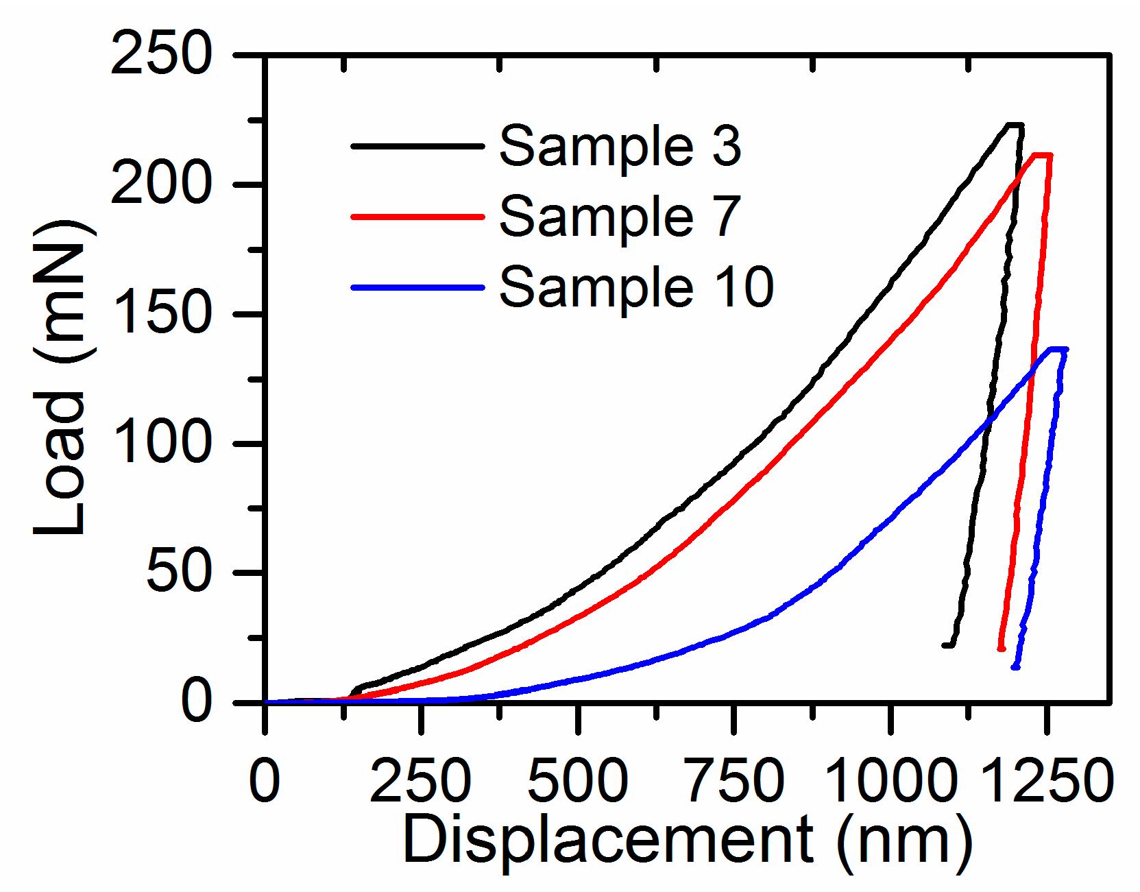
4. Mechanical Properties of nc-Ni Coatings

Among the mechanical properties, hardness, H, and elastic modulus, E, have received considerable attention [30,31]. Here, we include a survey of how variations in texture and grain size, tailored by process parameters, affect E and H. Three series of nanoindentation experiments were performed, which are listed in Table 1. Figure 8 presents three representative nanoindentation load-displacement curves for samples 3, 7, and 10 listed in Table 1. For the same 1200 nm penetration depth, sample 3 has the maximum load compared to the others, which indicates it has the highest hardness. According to the load-displacement curves, the hardness and elastic modulus of these coatings could be calculated as shown in Table 2.

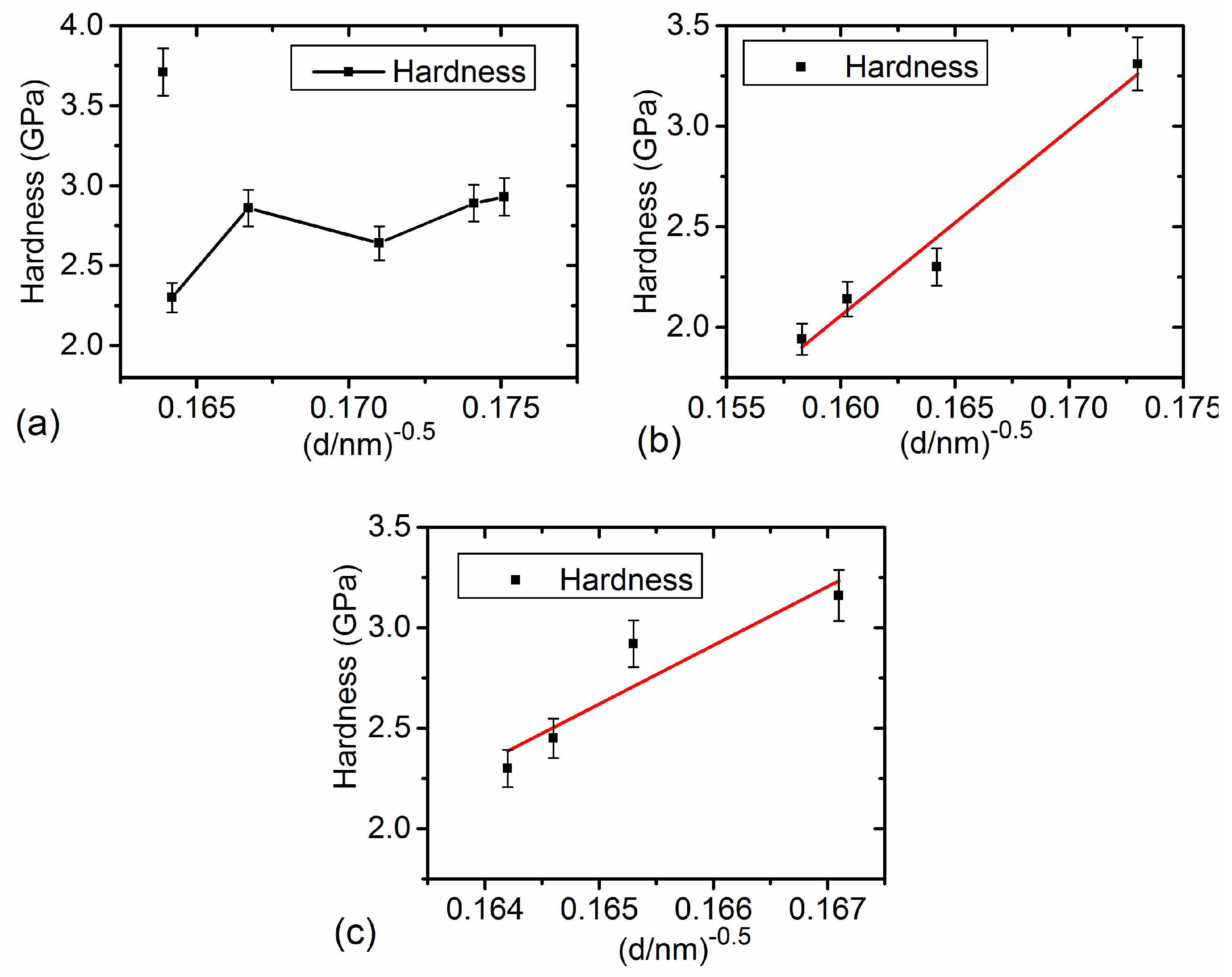
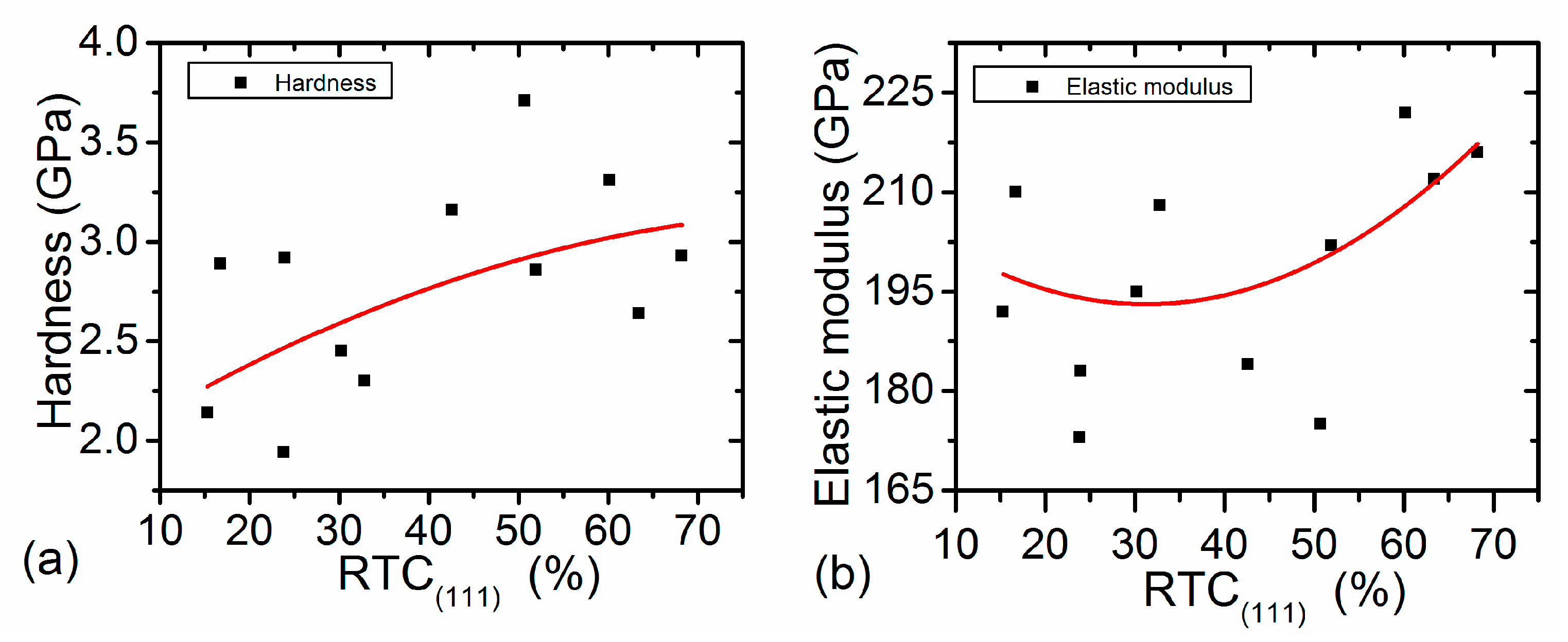
4.1. Hardness in Link with Structural Characteristics

Many researchers have demonstrated that grain size plays a dominant role in the final hardness of deposits. The relationship between hardness and grain size can be expressed by the Hall-Petch equation [32]:
H = H 0 + k d 0.5
where H 0 is the hardness constant, k is an additional constant, and d is the diameter of grains, which shows a smaller grain size corresponds to a higher hardness. The Hall-Petch relation is satisfied by many experiments, but there are some exceptions [18,32].
The effect arising from texture formation is another important factor. Godon et al. [18] reported experimental findings that illustrate the effect of crystallographic texture on the relationship between grain size and flow stress. Also, texture together with grain boundary structure has a key determining role in the mechanical properties in addition to the grain size [14,15]. In this study, systematic experiments were performed to investigate hardness-related issues. The dependence of the coating hardness on the employed deposition conditions is given in Table 2. In agreement with the literature [28], the hardness of nc-Ni coatings varied from 1.94 ± 0.3 to 3.71 ± 0.3 GPa.
Detailed information about the influence of process variables on hardness can be deduced from these experimental data. First, we analyzed the effect of current density on the hardness of deposits. From Table 2, we can see that when changing the current density from 1.5 A·dm−2 to 4.0 A·dm−2, the coating reached its maximum hardness of 3.71 ± 0.3 GPa at a current density of 2.5 A·dm−2 and its minimum value of 2.3 ± 0.3 GPa at 2.0 A·dm−2. This observation may be due to variations in the grain size as well as microstructure changes. Pathak et al. [19] found that the Ni coating hardness decreased slowly from 3.46 to 2.49 GPa with increasing current density, while the opposite trend was observed in [33] in which the hardness increased with increasing current density. However, our experimental results show that current density affects the hardness by means of tailoring the grain size and texture. For example, when the current density changed from 1.5 A·dm−2 to 2.0 A·dm−2, the texture coefficient of the (111) orientation (see Figure 4a) increased, causing the enhancement of hardness, while the average grain size (see Figure 4b) increased, leading to a reduction in hardness. The competition between them leads to a hardness reduction. As indicated in [32], it was shown that the nc-Ni coatings with (111) textures possess a higher strength compared to coatings with (100) and (220) textures. When the current density increased to 2.5 A·dm−2, the RTC(111) increased, and grain size decreased. The two factors consistently improved the hardness.
When the current density and pH value were held constant, from Table 2, we find that the hardness continuously decreased with increasing bath temperature, which was the expected result. Similar results were also reported by Kang et al. [17]. It can be explained by considering the microstructure variations. In such a case, the average grain size (see Figure 6b) increases with raising the bath temperature, leading to the reduction of deposit hardness, and RTC(111) decreases with increasing temperature, which also causes the reduction of hardness. Thus, the ultimate hardness decreased with increasing temperature. When keeping the current density and bath temperature fixed, we can see that the hardness goes from 3.16 GPa (pH 3.5) to 2.3 GPa (pH 4.0). This is a big change. Given the negligible change in grain size, as shown in Figure 6d, this big change is attributed to texture, as shown in Figure 6c. When further increasing the pH values, there are no significant changes in magnitude of hardness. Ultimately, this work begs the question that there is some relationship between hardness and texture analogous to a Hall-Petch relationship, which will be further investigated.
To further clarify the grain size effect, the relationship between d−0.5 and hardness is presented in Figure 9 under different process conditions. It is interesting to find that this relationship has different forms under the three tested process conditions. As shown in Figure 9a, the Hall-Petch relationship breaks down when changing the current density. This result suggests that the well known grain-boundary strengthening is not the dominant factor for the hardness of nc-Ni coatings under such process conditions. As discussed above, other factors, such as texture, also affect hardness. However, the d−0.5 and hardness follows the Hall-Petch relationship very well when changing the bath temperature as shown in Figure 9b. This result reveals that the grain size strengthening is the dominant factor for the hardness response when changing the bath temperature. Similarly, the hardness follows the Hall-Petch relation approximately, when changing pH values, while the slope is different from that when changing the bath temperature. This experimental result implies that the action modes of different process variables on hardness are different. It is usually assumed that the behavior of materials following the Hall-Petch equation is controlled by the deformation of grains. As indicated by Godon [18] and Matsui [15], the distribution of grain orientations and GB types can clearly modify the physical basis of the Hall-Petch law and influence the slope, k.
Second, regarding the effect of texture on hardness, Figure 10a presents the relationship between hardness and RTC(111) of all the samples. It reveals that when RTC(111) changes from 15.3% to 68.2%, the overall trend of hardness increases gradually, though some points deviate from this trend due to the influence of grain size. The Hall-Petch effect is attributed to the grain boundaries acting as efficient obstacles for the accumulation of dislocation inside a grain. However, the present investigation found that the texture effect provides a new opportunity to revise the mechanisms proposed to account for GB and grain deformation.

4.2. Elastic Modulus in Link with Structural Characteristics

Usually, hardness is strongly dependent on grain size, which has less influence on the elastic modulus. Many publications have indicated that for a given composition, E is lower for films with smaller crystalline sizes. For example, the elastic modulus of nanocrystalline materials is lower than that of coarse-grained materials by as much as 70% in some cases [25]. In contrast to grain size, texture formation is a prime consideration controlling the elastic modulus [34,35]. To clarify this issue, we define the elastic modulus as E111 for a (111) texture, E110 for a (110) texture, and E100 for (100) texture. E111, E110, and E100 can be measured and calculated. It shows that E111 > E110 > E100 and thus the deposit with higher RTC(111) has a higher value of E [34]. Thus, texture is an important parameter that can be used to predict and analyze the change of elastic modulus.
First, we analyzed the effect of current density on the elastic modulus. Many prior works suggested that pure nickel coatings prepared at lower current densities possess smoother, denser microstructures and higher elastic moduli [19]. It was also found the change of deposition current density shows little effect upon the deposit response to indentation [25]. Our experimental results showed that when the current density changes from 1.5 to 4.0A dm−2, while keeping both temperature and pH value fixed, there exists two stages in the value of elastic modulus from Table 2. In the first stage, the elastic modulus decreases from 210 ± 4.2 to 175 ± 5.1 GPa when current density increases from 1.5 A·dm−2 to 2.5 A·dm−2, while in the second stage, the elastic modulus increases from 175 ± 5.1 to 216 ± 5.2 GPa with a further increase in current density.
Contrary to the case of changing current density, the effect of process temperature variation on the elastic modulus is direct and clear. It is clear from Table 2 that the elastic modulus decreases from 222.8 ± 4.1 to 172.7 ± 3.9 GPa when the temperature increases from 45 to 60 °C. Similar results can be found in previous publications [20]. The decrease of elastic modulus with increasing plating temperature in the present study can be explained from the viewpoint of microstructure variations. From Figure 6b, we can see that the grain size increases with bath temperature, leading to an increase in the elastic modulus. Since grains with (220) texture have lower modulus values for Ni than grains with (111) texture, the decrease in the elastic modulus with the bath temperature is also a direct consequence of the change in the grain texture from (111) to (220), as shown in Figure 6a. The combined effects determine the reduction of the elastic modulus with increasing temperature.
As a key process parameter, the pH value also has an influence on the elastic modulus. Elastic modulus ranging between 183.8 ± 4.1 and 208 ± 4.3 GPa were obtained for the deposits when the pH changed from 3.5 to 5.0 while maintaining the other parameters from Table 2. This variation can be clarified by accounting for the microstructural characteristics of nc-Ni coatings. For example, when the pH increases to 4.5, RTC(111) further decreases, leading to the reduction of E, while the grain size along the (111) orientation increases, causing the enhancement of E. Here, the final elastic modulus decreases. This result demonstrates that texture is a dominant factor on E. With an increasing pH to 5.0, RTC(111) begins to increase, causing the enhancement of E, further implying the dominant effect of texture on E. In summary, the variations of E with process parameters can be partly explained by considering the corresponding changes in structural characteristics, like texture and grain size. Among these factors, texture related to elastic anisotropy takes a dominant effect.
From the above work, we are keen to know about the fundamental relationship between modulus and texture. A relationship between modulus and RTC(111) is disclosed in Figure 10b for the first time. It shows that the variation of modulus with texture is divided into two stages, namely, the first stage when RTC(111) is smaller than 40%, and the second stage when RTC(111) exceeds 40%. We cannot find some relationship between texture and modulus in the first stage; however, in the second stage, it is apparent that modulus increases with RTC(111). It can be explained that when RTC(111) is smaller than 40%, implying (111) orientation is not a preferred orientation, and its influence on modulus is slight, we cannot get the definite trend between them. However, when RTC(111) exceeds 40%, implying (111) orientation is preferred, the modulus increases with RTC(111), further denoting the importance of elastic anisotropy.

5. Conclusions

The correlations among the process parameters, microstructure, and mechanical properties of nc-Ni coatings were disclosed through a consistent set of experiments in this work. Several important and interesting findings, which are uncommon and often ignored, were revealed. The main conclusions can be summarized as follows:
(1) For nc-Ni coatings with FCC structures, a direct correlation between the grain size and texture was disclosed quantitatively for the first time. The grain size of the (111) crystalline plane decreases with RTC(111) regardless of the process conditions, but that of the (220) plane barely changes with increasing RTC(220) when changing the current density or electrolyte pH. The grain size of (220) does increase with texture when changing the bath temperature. These results denote that the change in temperature has a great influence on the grain size; however, the electrolyte pH has a minor effect on the grain size.
(2) Another important finding is that the dependence of the grain size on hardness is accurately described by the Hall-Petch relationship in the case of changing bath temperatures and electrolyte pH values, while it breaks down when changing current densities. The hardness discrepancy from the Hall-Petch relation can be principally attributed to texture formation and the compactness of deposits. The Hall-Petch slope depends on texture in relation to the distribution of grain boundaries, controlled by process parameters. Regarding the effect of texture, it was found that the overall trend of hardness increases with increasing of RTC(111).
(3) The elastic modulus decreases almost linearly with an increase in temperature, but the electrolyte pH has little effect on the elastic modulus. The elastic modulus vs. process parameters revealed that this may be explained by considering the superposition of prevailing effects related to grain size and texture formation. An important finding was that when RTC(111) exceeds 40%, modulus increases with RTC(111). In contrast to the case of hardness, texture formation prevails over the other two factors for the elastic modulus values, which denotes that the elastic anisotropy has a great influence.

Author Contributions

L.F. wrote the original manuscript and conceived experiments. Y.-y.R. performed the experiments, S.W. and L.L. supervised experimental work, revised the manuscript.

Funding

The authors acknowledge the financial support from the National Natural Science Foundation of China (Grant Nos. 11272231, 11472186, 11572218).

Conflicts of Interest

The authors declare no conflict of interest.

References

  1. Beltowska-Lehman, E.; Bigos, A.; Indyka, P.; Chojnacka, A.; Drewienkiewicz, A.; Zimowski, S.; Kot, M.; Szczerba, M.J. Optimisation of the electrodeposition process of Ni-W/ZrO2 nanocomposites. J. Electroanal. Chem. 2018, 813, 39–51. [Google Scholar] [CrossRef]
  2. Sajjadnejad, M.; Omidvar, H.; Javanbakht, M.; Mozafari, A. Textural and structural evolution of pulse electrodeposited Ni/diamond nanocomposite coatings. J. Alloy. Compd. 2017, 704, 809–817. [Google Scholar] [CrossRef]
  3. Kim, K. Measurement and analysis of friction and wear on electrodeposited coatings against a high carbon chrome steel ball. J. Mater. Res. 2016, 31, 1865–1872. [Google Scholar] [CrossRef]
  4. Awasthi, S.; Pandey, C.P.; Balani, K. Synergistic role of carbonaceous reinforcements on multi length scale tribology of electrophoretically deposited nickel-boron nitride coatings. Mater Res Bull. 2018, 99, 61–72. [Google Scholar] [CrossRef]
  5. Ziebell, T.D.; Schuh, C.A. Residual stress in electrodeposited nanocrystalline nickel-tungsten coatings. J. Mater. Res. 2012, 27, 1271–1284. [Google Scholar] [CrossRef]
  6. Shen, X.; Wu, M.; Ji, D.; Xu, Q.; Cheng, D. The mechanical behavior of a layered nanostructured Ni with an alternating growth of ultrafine grains and nano-sized grains fabricated by electrodeposition. Mater. Sci. Eng. A 2018, 713, 43–51. [Google Scholar] [CrossRef]
  7. Bakonyi, I.; Toth-Kadar, E.; Tarnoczi, T.; Varga, L.K.; Cziraki, A.; Gerocs, I.; Fogarassy, B. Structure and properties of fine-grained electrodeposited nickel. Nanostruct. Mater. 1993, 3, 155–161. [Google Scholar] [CrossRef]
  8. Bakonyi, I.; Toth-Kadar, E.; Pogany, L.; Cziraki, A.; Gerocs, I.; Varga-Josepovits, K.; Arnold, B.; Wetzig, K. Preparation and characterization of DC-plated nanocrystalline nickel electrodeposits. Surf. Coat. Technol. 1996, 78, 124–136. [Google Scholar] [CrossRef]
  9. Toth-Kadar, E.; Bakonyi, I.; Pogany, L.; Czira’ki, A. Microstructure and electrical transport properties of pulse-plated nanocrystalline nickel electrodeposits. Surf. Coat. Technol. 1997, 88, 57–65. [Google Scholar] [CrossRef]
  10. Rashidi, A.M.; Amadeh, A. Effect of electroplating parameters on microstructure of nanocrystalline nickel coatings. J. Mater. Sci. Technol. 2010, 26, 82–86. [Google Scholar] [CrossRef]
  11. Sarac, U.; Baykulb, M.C. Morphological and microstructural properties of two-phase Ni–Cu films electrodeposited at different electrolyte temperatures. J. Alloy. Compd. 2013, 552, 195–201. [Google Scholar] [CrossRef]
  12. Haciismailoglu, M.; Alper, M. Effect of electrolyte pH and Cu concentration on microstructure of electrodeposited Ni–Cu alloy films. Surf. Coat. Technol. 2011, 206, 1430–1438. [Google Scholar] [CrossRef]
  13. Boubatra, M.; Azizi, A.; Schmerber, G.; Dinia, A. The influence of pH electrolyte on the electrochemical deposition and properties of nickel thin films. Ionics 2012, 18, 425–432. [Google Scholar] [CrossRef]
  14. Ghosh, P.; Petegem, S.V.; Swygenhoven, H.V.; Chokshi, A.H. An in-situ synchrotron study on microplastic flow of electrodeposited nanocrystalline nickel. Mater. Sci. Eng. A 2017, 701, 101–110. [Google Scholar] [CrossRef]
  15. Matsui, I.; Kanetake, M.; Mori, H.; Takigawa, Y.; Higashi, K. Relationship between grain boundary relaxation strengthening and orientation in electrodeposited bulk nanocrystalline Ni alloys. Mater. Lett 2017, 205, 211–214. [Google Scholar] [CrossRef]
  16. Nasirpouri, F.; Sanaeian, M.R.; Samardak, A.S.; Sukovatitsina, E.V.; Ognev, A.V.; Chebotkevich, L.A.; Hosseini, M.G.; Abdolmaleki, M. An investigation on the effect of surface morphology and crystalline texture on corrosion behavior, structural and magnetic properties of electrodeposited nanocrystalline nickel films. Appl. Surf. Sci 2014, 292, 795–805. [Google Scholar] [CrossRef]
  17. Kang, J.; Zhao, W.; Zhang, G. Influence of electrodeposition parameters on the deposition rate and microhardness of nanocrystalline Ni coatings. Surf. Coat. Technol. 2009, 203, 1815–1818. [Google Scholar] [CrossRef]
  18. Godon, A.; Creus, J.; Cohendoz, S.; Conforto, E.; Feaugas, X.; Girault, P.; Savall, C. Effects of grain orientation on the Hall–Petch relationship in electrodeposited nickel with nanocrystalline grains. Scripta Mater. 2010, 62, 403–406. [Google Scholar] [CrossRef]
  19. Pathak, S.; Guinard, M.; Vernooij, M.G.C.; Cousin, B.; Wang, Z.; Michler, J.; Philippe, L. Influence of lower current densities on the residual stress and structure of thick nickel electrodeposits. Surf. Coat. Technol. 2011, 205, 3651–3657. [Google Scholar] [CrossRef]
  20. Baskaran, I.; Narayanan, T.S.N.S.; Stephen, A. Pulsed electrodeposition of nanocrystalline Cu–Ni alloy films and evaluation of their characteristic properties. Mater. Lett. 2006, 60, 1990–1995. [Google Scholar] [CrossRef]
  21. Savall, C.; Godon, A.; Creus, J.; Feaugas, X. Influence of deposition parameters on microstructure and contamination of electrodeposited nickel coatings from additive-free sulphamate bath. Surf. Coat. Technol. 2012, 206, 4394–4402. [Google Scholar] [CrossRef]
  22. Bolelli, G.; Candeli, A.; Lusvargh, L.; Manfredini, T.; Denoirjean, A.; Valette, S.; Ravaux, A.; Meillot, E. “Hybrid” plasma spraying of NiCrAlY+Al2O3+h-BN composite coatings for sliding wear applications. Wear 2017, 68, 378–379. [Google Scholar]
  23. Bund, A.; Thiemig, D. Influence of bath composition and pH on the electrocodeposition of alumina nanoparticles and nickel. Surf. Coat. Technol. 2007, 201, 7092–7099. [Google Scholar] [CrossRef]
  24. Oliver, W.C.; Pharr, G.M. An improved technique for determining hardness and elastic modulus using load and displacement sensing indentation experiments. J. Mater. Res. 1992, 7, 1564–1583. [Google Scholar] [CrossRef]
  25. Pellicer, E.; Varea, A.; Pané, S.; Sivaraman, K.M.; Nelson, B.J.; Suriñach, S.; Baró, M.D.; Sort, J. A comparison between fine-grained and nanocrystalline electrodeposited Cu–Ni films. Insights on mechanical and corrosion performance. Surf. Coat. Technol. 2011, 205, 5285–5293. [Google Scholar] [CrossRef]
  26. Godon, A.; Creus, J.; Feaugas, X.; Conforto, E.; Pichon, L.; Armand, C.; Savall, C. Characterization of electrodeposited nickel coatings from sulphamate electrolyte without additive. Mater. Charact. 2011, 62, 164–173. [Google Scholar] [CrossRef]
  27. Oriňáková, R.; Oriňák, A.; Vering, G.; Talian, I.; Smith, R.M.; Arlinghaus, H.F. Influence of pH on the electrolytic deposition of Ni–Co films. Thin Solid Films 2008, 516, 3045–3050. [Google Scholar] [CrossRef]
  28. Moharana, M.; Mallik, A. Nickel electrocrystallization in different electrolytes: An in-process and post synthesis analysis. Electrochimica. Acta. 2013, 98, 1–10. [Google Scholar] [CrossRef]
  29. Xue, Z.; Lei, W.; Wang, Y.; Qian, H.; Li, Q. Effect of pulse duty cycle on mechanical properties and microstructure of nickel-graphene composite coating produced by pulse electrodepositionunder supercritical carbon dioxide. Surf. Coat. Technol. 2017, 325, 417–428. [Google Scholar] [CrossRef]
  30. Sribalaji, M.; Asiq Rahman, O.S.; Laha, T.; Keshri, A.K. Nanoindentation and nanoscratch behavior of electroless deposited nickel-phosphorous coating. Mater. Chem. Physics 2016, 177, 220–228. [Google Scholar] [CrossRef]
  31. Müller, T.; Grimwood, J.; Bachmaier, A.; Pippan, R. Electrodeposition of Fe-C alloys from citrate baths: structure, mechanical properties, and thermal stability. Metals 2018, 8, 363. [Google Scholar] [CrossRef]
  32. Wang, L.; Gao, Y.; Xu, T.; Xue, Q. A comparative study on the tribological behavior of nanocrystalline nickel and cobalt coatings correlated with grain size and phase structure. Mater. Chem. Phys. 2006, 99, 96–103. [Google Scholar] [CrossRef]
  33. Mishra, A.C.; Thakur, A.K.; Srinivas, V. Effect of deposition parameters on microstructure of electrodeposited nickel thin films. J. Mater. Sci. 2009, 44, 3520–3527. [Google Scholar] [CrossRef]
  34. Torrents, A.; Yang, H.; Mohamed, A.F. Effect of annealing on hardness and the modulus of elasticity in bulk nanocrystalline nickel. Metall. Mater. Trans. A 2010, 41, 621–630. [Google Scholar] [CrossRef]
  35. Milstein, F.; Chantasiriwan, S. Theoretical study of the response of 12 cubic metals to uniaxial loading. Phys. Rev. B 1998, 58, 6006–6018. [Google Scholar] [CrossRef]
Figure 1. (a) Effects of temperature and (b) pH value on the cathode polarization of Ni electrodeposition from the modified Watts bath.
Metals 09 00188 g001
Figure 2. Surface morphologies and cross-sectional SEM micrographs (backscattered electrons mode) of Ni films plated at current densities: (a,b) 1.5 A/dm2; (c,d) 3.5 A·dm−2.
Metals 09 00188 g002
Figure 3. XRD spectra of nc-Ni coatings prepared at different current densities.
Metals 09 00188 g003
Figure 4. (a) Variation of RTC(hkl) for different diffraction peaks with varied current densities; (b) effect of current density on grain size from different diffraction peaks and average grain size.
Metals 09 00188 g004
Figure 5. TEM bright-field images, selected area electron diffraction, and grain size distribution of the nickel coatings: (a,b) for the coating deposited at 2.0 A·dm−2; (c,d) for the coating deposited at 4.0 A·dm−2.
Metals 09 00188 g005
Figure 6. Variation of RTC(hkl) and grain size from different diffraction peaks: (a,b) with bath temperature; (c,d) with pH.
Metals 09 00188 g006
Figure 7. Relationship between the grain size and texture coefficient under different deposition conditions from: (a) the (111) peak; (b) the (220) peak.
Metals 09 00188 g007
Figure 8. Representative load-displacement curves of nanoindentation tests for three samples.
Metals 09 00188 g008
Figure 9. Hardness of nc-Ni coatings as a function of the inverse square root of the grain size under different process conditions: (a) changing current density; (b) changing bath temperature; (c) changing pH value.
Metals 09 00188 g009
Figure 10. (a) Variation of hardness with RTC111; (b) variation of elastic modulus with RTC111.
Metals 09 00188 g010
Table 1. Process conditions for the three groups of electrodeposition tests.
SampleVaried Parameters
Current density (A dm−2) (T = 50 °C, pH 4)11.5
22
32.5
43
53.5
64
Temperature (°C) (pH 4, I = 2 A·dm−2)745
850
955
1060
pH (I = 2 A·dm−2, T = 50 °C)113.5
124
134.5
145
Table 2. Hardness and elastic modulus of nc-Ni coatings deposited under different process conditions.
j (A·dm2)H (GPa)E (GPa)T (°C)H (GPa)E (GPa)pHH (GPa)E (GPa)
1.52.89 ± 0.3210.0 ± 4.2453.31 ± 0.3222.8 ± 4.13.53.16 ± 0.3184.4 ± 3.8
2.02.30 ± 0.3208.0 ± 3.4502.30 ± 0.3208.0 ± 5.34.02.30 ± 0.3208.0 ± 4.3
2.53.71 ± 0.3175.0 ± 5.1552.14 ± 0.3191.7 ± 4.34.52.92 ± 0.3183.8 ± 4.1
3.02.86 ± 0.3202.4 ± 3.6601.94 ± 0.3172.7 ± 3.95.02.45 ± 0.3195.2 ± 3.9
3.52.64 ± 0.3212.0 ± 3.8
4.02.93 ± 0.3216.0 ± 5.2

