Article

Numerical Simulation Analysis of Dual-Beam Laser Welding of Tailored Blanks with Different Thicknesses

1
School of Mechanical and Aerospace Engineering, Jilin University, Changchun 130025, China
2
State Key Laboratory of Advanced Welding and Joining, Harbin Institute of Technology, Harbin 150001, China
*
Author to whom correspondence should be addressed.
Metals 2019, 9(2), 135; https://doi.org/10.3390/met9020135
Submission received: 6 December 2018 / Revised: 23 January 2019 / Accepted: 24 January 2019 / Published: 26 January 2019
(This article belongs to the Special Issue Application of Numerical Simulation in Welding)

Abstract

:
In order to meet the requirements of alignment capability, gap tolerance and welding track control, dual-beam laser welding has been put forward to weld tailored blanks with different thicknesses. The arrangement mode and power ratio of dual-beam laser determine the heat transfer and temperature field distribution, and then influence the weld profile and weld quality. In this study, based on consideration of the temperature dependence of material physical properties, convection and radiation heat transfer, and material latent heat, the finite element model was developed. The model validated was conducted to compare with experimental results and it showed good agreement. The arrangement mode and power ratio of dual-beam laser welding were compared and optimized based on the consideration of the weld width on top surface and gap tolerance. Finally, the temperature field characteristics with the preferable process were analyzed in detail according to the numerical simulation. The calculated results indicated the weld width is mainly controlled by the laser irradiation on the thin plate, and dual-beam laser welding of tailored blanks has great advantages on improving heat transfer, weld profile and gap tolerance, which helps to reduce welding defects and enhance welding quality.

1. Introduction

Tailor-welded blanks (TWBs) technology is widely used in car body manufacturing, which are defined as tailored blanks with different thicknesses, material or properties welded together and then formed. The advantages of TWBS technology is improving car manufacturing accuracy, reducing the weight of the car body, saving manufacturing cost, reducing pollution, and so on [1,2,3]. Tailored blanks have been welded using many welding methods [4,5,6,7,8,9,10,11]. Owing to the high welding velocity, low welding thermal distortion and high operation flexibility, the research of tailored blanks welding has been mainly focused on laser welding in past decades. However, because the diameter of the laser beam focused spot is small, the requirements for alignment capability, gap tolerance and welding track control are very high during single laser welded tailored blanks. Hence, dual-beam laser welding has been put forward to weld tailored blanks with different thicknesses to solve the above problems [12]. However, in previous studies, there are few investigations on numerical simulation of dual-beam laser welded tailored blanks with different thicknesses because of the complex process and mechanisms.
Numerical simulation is an important means to explain the physical mechanism and optimize the process of laser welding, which began in 1970s. Swif-Hook et al. [13] first put forward a line heat source model to achiev the analytical solution for laser welding. Steen [14] used a point source which was added near the surface of the workpiece to correspond to the semi-circular region at the top of the weld on the basis of the line source. Kazemi et al. [15] developed a hybrid heat source that combined the circular disk source and line source to simulate the laser full penetration welding process, and the calculated result was nearly the same to that of experimental result. Shanmugam et al. [16] established a finite element model with conical Gaussian heat source to model temperature distribution and weld profile of laser welding of the T-joint, and the calculated errors of the weld depth and width were only 2.78% and 1.9%, when comparing the experiment and simulation results. Yu et al. [17,18] used Gaussian function heat source model to calculate temperature and stress-strain field of laser welded aluminum plate with different thicknesses. However, there were no more reports on laser welding of tailored blanks with different thicknesses because of too many complicated factors for numerical simulation.
Some studies on numerical simulation of dual-beam laser welding were carried out. Hu et al. [19,20] developed mathematical models to simulate transient heat transfer and weld pool flow in the dual-beam laser welding process. On the basis of Hu’s model, Zhou et al. [21] further developed a three-dimensional moving heat-flow coupling model, and studied the flow field and temperature field of molten pool under different configurations of lasers (longitudinal arrangement and traverse arrangement) for dual-beam laser welding. Hou [22] used one laser beam to assist and the other laser beam was used to weld, and the distance between dual-beam laser was larger than laser beam focused spot diameter. Liu et al. [23] fulfilled the numerical simulation analysis during dual-beam laser (longitudinal arrangement) welding involving the application of one laser beam as the major heat source hybrid on a defocused laser beam as preheating, and the simulation results showed that the cooling rates effectively reduced. However, to the best of the authors’ knowledge, there are few studies on numerical simulation of dual-beam laser (traverse arrangement) welding of tailored blanks with different thicknesses in previous literature.
In the present study, a three-dimensional mathematical model is developed to perform the numerical simulation analysis during dual-beam laser (traverse arrangement) welding of tailored blanks with different thicknesses. According to numerical simulation based on the mathematical model, the effects of the arrangement mode and power ratio of dual-beam laser on the weld width were evaluated and optimized. Finally, the distribution characteristics of temperature field were analyzed in detail.

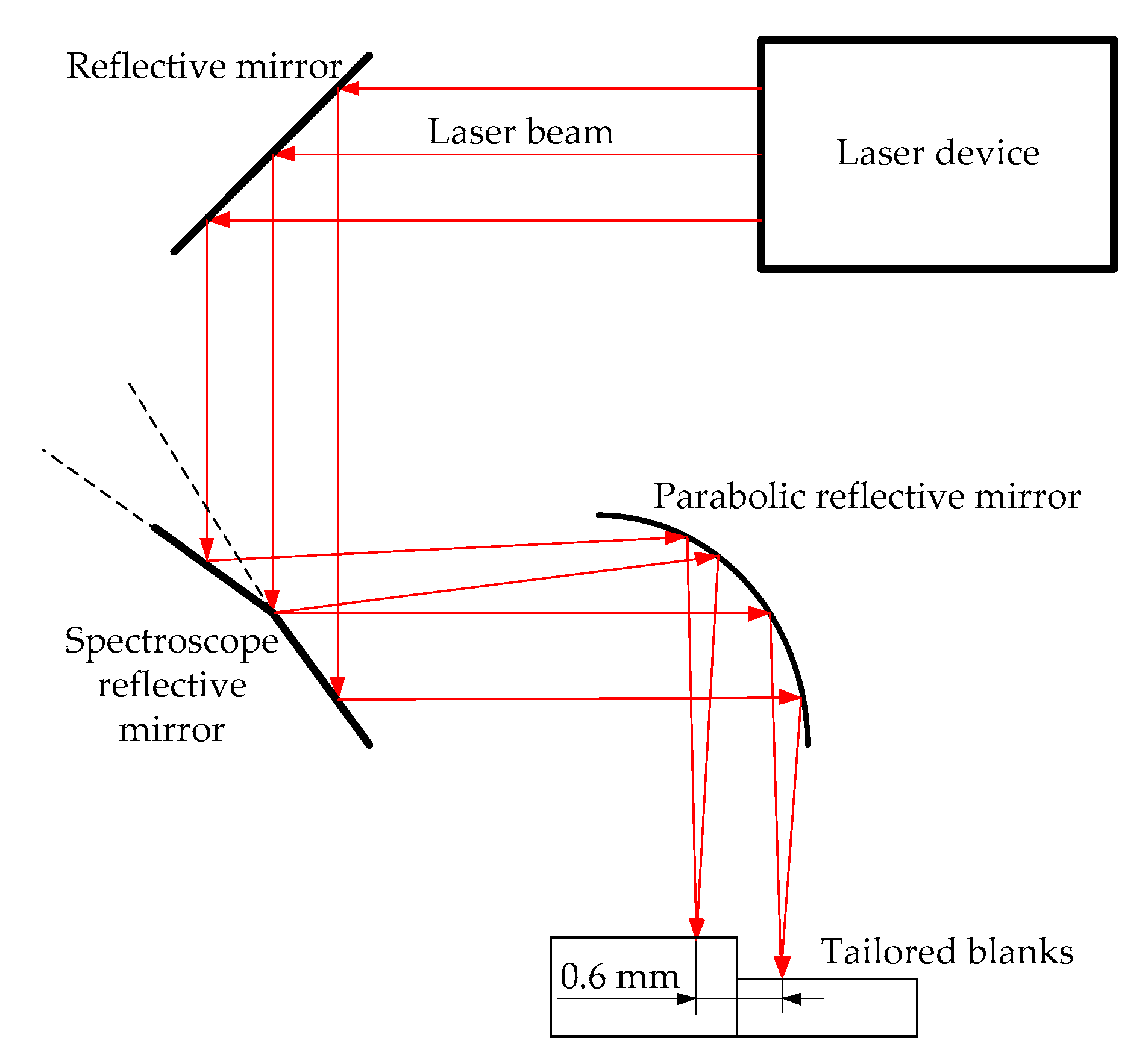
2. Experimental Procedure

To confirm the mathematical model and calculation results, the dual-beam laser welding of tailored blanks experiment was performed using a CO2 laser equipment (DC-030, ROFIN-SINAR Corp., Hamburg, Germany) and the fixture mechanisms. In present study, one CO2 laser beam was divided into a parallel dual-beam laser with a distance of 0.6 mm as shown in Figure 1 by a spectroscope, which was used to weld tailored blanks with different thicknesses. The rayleigh length of focused laser beam is 2.14 mm and the characteristic parameter of focused laser beam is 3.78 mm.mrad. The schematic diagram of dual-beam laser welded tailored blanks with different thicknesses is displayed in Figure 1. Two laser beams with different energy ratios were obtained by changing the irradiation area ratio of the upper and lower parts of a single laser beam on the spectroscope mirror, and the focal spots of the two laser beams were circular. The tailored blanks joints were comprised of steel plates with 1.4 and 0.8 mm respectively. The bottom surfaces of tailored blanks were leveled. The dual-beam laser was focused on the top surfaces of the tailored blanks. The radius of focused spot was 0.2 mm. The shielding gas was pure argon with a flow rate of 25 L/min. The chemical compositions of carbon structure steel (Trade name: Q195) plate are illustrated in Table 1.
After welding, the welded joint of tailored blanks was sectioned, mounted, and then polished using the solution of 5 vol% HNO3 and 95 vol% ethanol for about 15 s. The cross-section of welded joint was observed with optical microscope (E200, Nikon Co., Ltd., Tokyo, Japan).

3. Mathematical Modeling

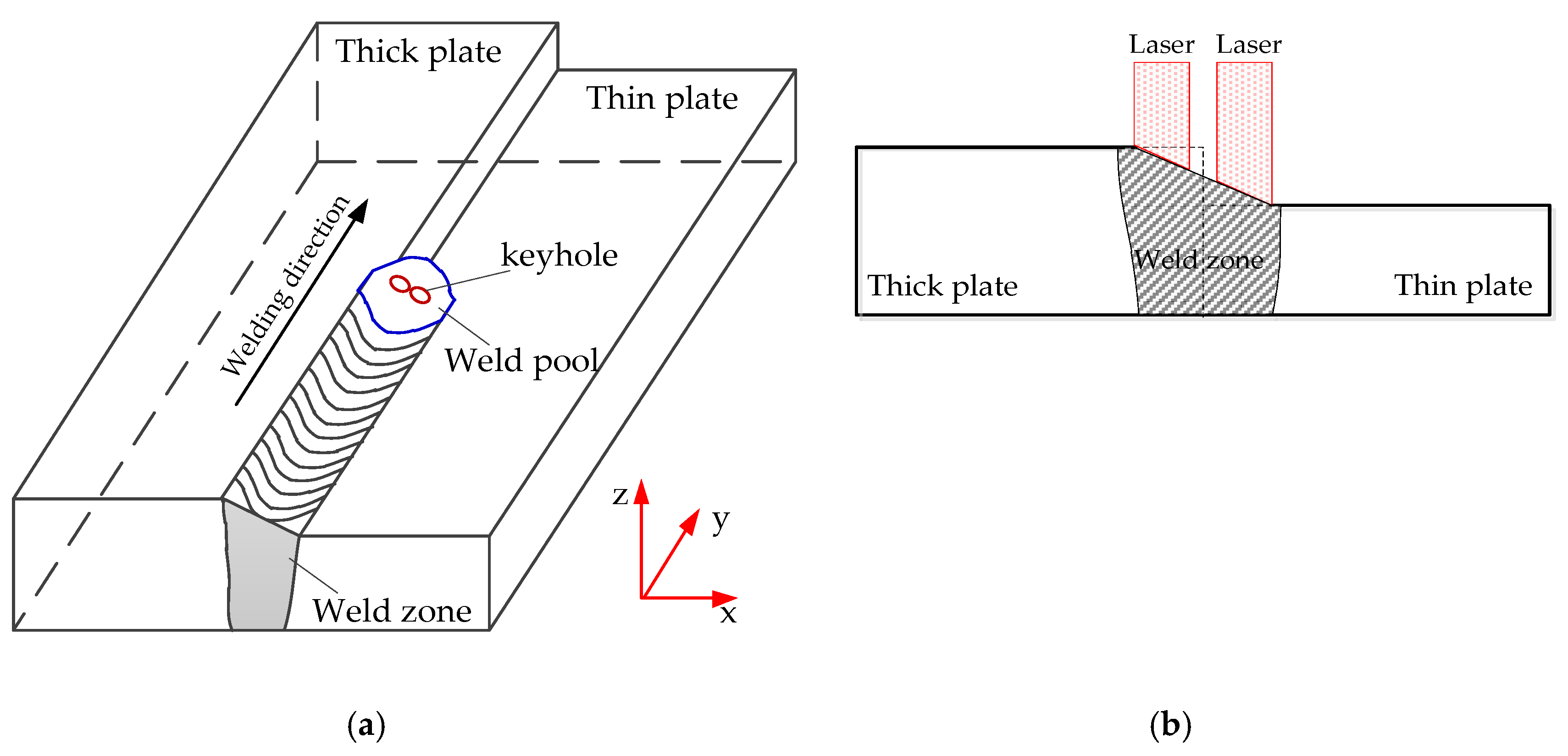
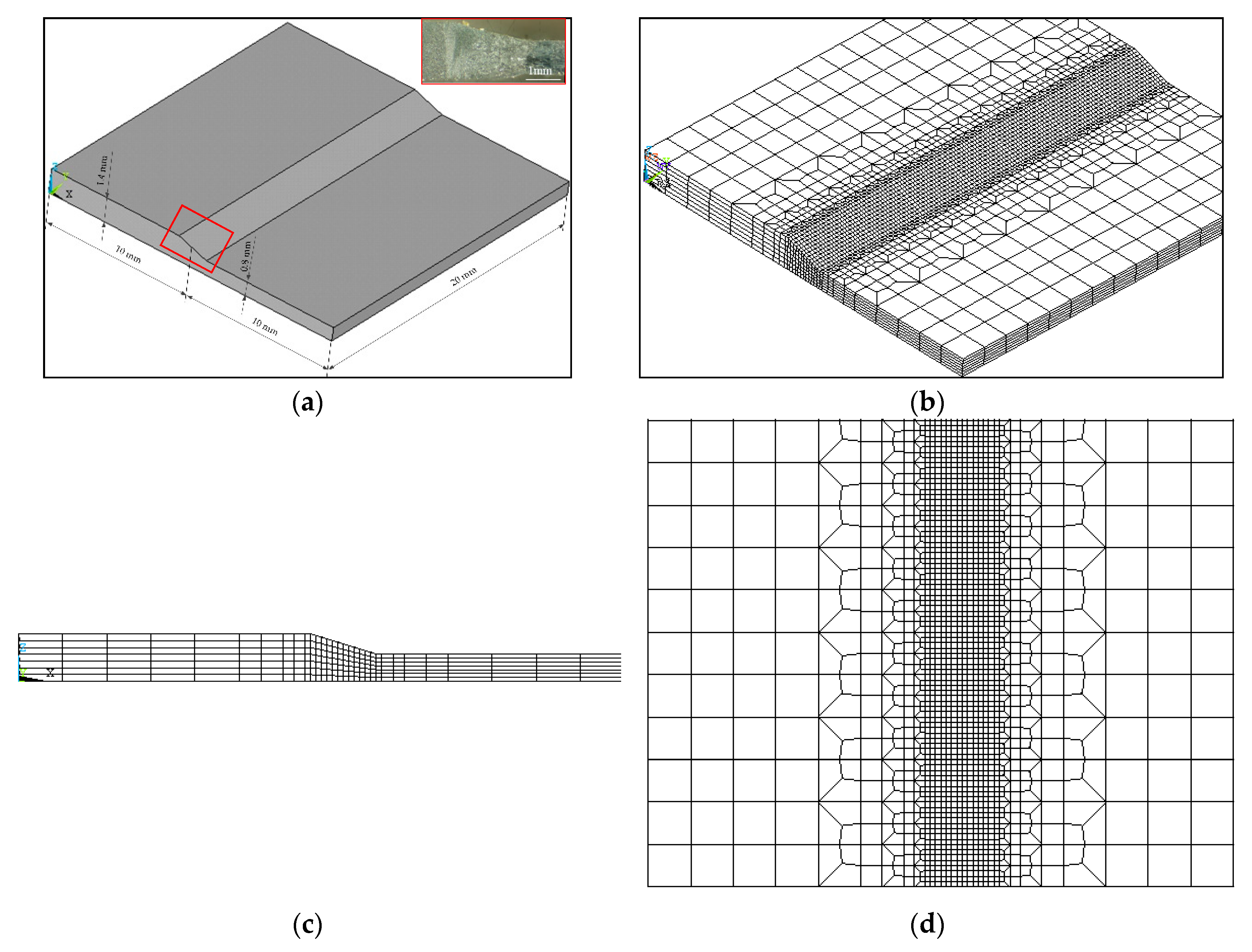
3.1. Model Description

While dual-beam laser welding of tailored blanks with different thicknesses was performed, the thick plate and thin plate were all locally melted, and so the tailored blanks were joined after the solidification of the molten pool. Due to the difference between the thickness of tailored blanks, while the bottom surfaces of tailored blanks were leveled, the top surface of weld zone was not flat, as shown in Figure 2. In this study, the distance between the dual-beam laser was fixed which was 0.6 mm, and two keyholes were generated in the molten pool. Meanwhile, the plasma was emitted from the two keyholes which converged together at the opening, and so single stable plasma was generated above the workpiece.
Due to the complex physical phenomena during the dual-beam laser welding process and considering the number of calculations, the physical model was reasonably simplified. The main assumptions were as follows:
(1)
The welding process is quasi-steady state.
(2)
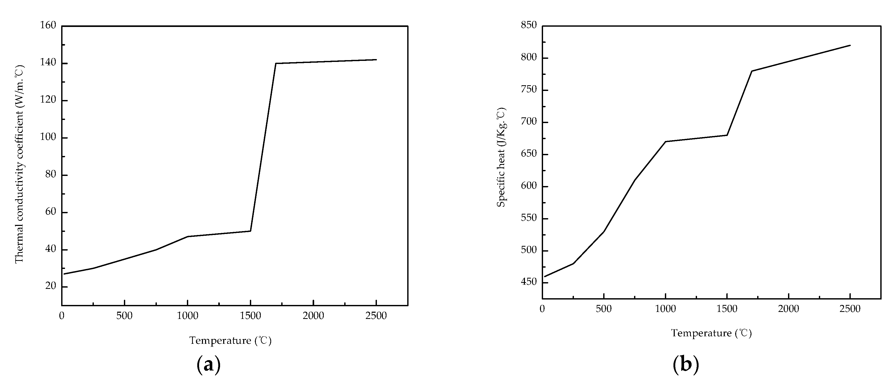
The material is isotropic and continuous medium, and some physical properties of material (thermal conductivity and specific heat) vary with temperature. The density of material is constant.
(3)
The weld shape was prefabricated based on the preliminary experimental results.
(4)
Above melting temperature, the effect of convection on heat transfer in weld pool (caused by molten pool flow) is compensated according to the increase in thermal conductivity of the material.
(5)
The surface absorption of melt material is constant.
(6)
The heat transfer by radiation and convection between the workpiece and ambient environment are considered.
(7)
The latent heat of solid-liquid phase transformation is considered, but the latent heats of solid phase transformation and evaporation (much smaller than that of the solid–liquid phase transformation) are all ignored.
(8)
The energy density of the laser beam is Gaussian distribution.
(9)
The ambient temperature is 20 °C.

3.2. Heat Source Model

In order to accurately study dual-beam laser energy coupled with tailored blanks, a combined heat source which consisted of a surface heat source above the weld pool surface and double body heat sources in the weld pool was modeled in the present work.

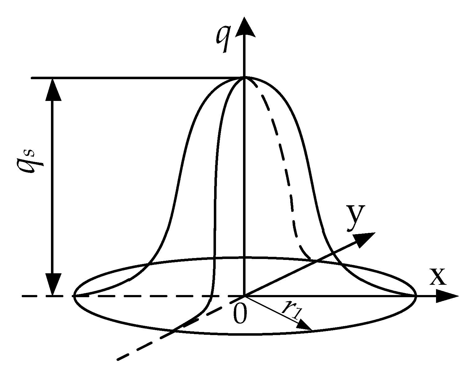
3.2.1. Surface Heat Source Model

The heat source model directly affects the computational accuracy of the dual-laser welding temperature field. For the dual-laser welding process, the plasma temperature was very high, and it should be considered to be a surface heat source with Gaussian distribution as shown in Figure 3. The heat flux density could be defined as:
q ( x , y ) = q s exp ( λ s ( x 2 + y 2 ) r 1 2 ) ,
where qs is the peak heat flux density, r1 is effective radius and λs is the concentrated coefficient for the surface heat source, and the peak heat flux density qs could be expressed as:
q s = λ s π r 1 2 p T η k ,
where pT is total laser power, η is coefficient of effective laser power, and k is coefficient of the surface heat source to total laser power.

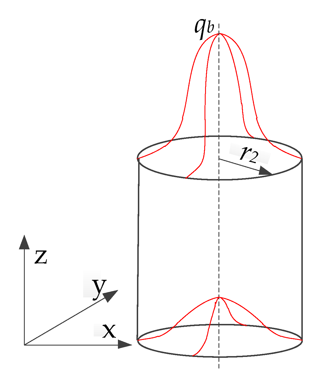
3.2.2. Body Heat Source Model

While the laser passed through the plasma above weld pool surface and entered the keyhole in weld pool, the laser should be coupled with plasma in the keyhole by the way of inverse bremsstrahlung absorption [24]. For simplicity in the present paper, it was considered that the laser energy was linearly attenuated in the keyhole thickness direction, namely:
p z = p T ( 1 η ) α A exp ( β z ) ,
where pz is the laser power at the z depth of the keyhole, α is the coupling coefficient, A is laser absorptivity ratio of material, β is laser attenuation coefficient. It is assumed that the laser power density of the X-Y cross-section of keyholes was also Gaussian distribution, and the keyhole was a cylinder as shown in Figure 4. The peak heat flux density qb could be expressed as:
q b = λ b π r 2 2 p z = λ b p T ( 1 η ) α A exp ( β z ) π r 2 2 ,
where λb is the concentrated coefficient of the body heat source, r2 is the bottom radius of the cylinder keyhole. The body heat source could be defined:
q ( x , y , z ) = q b exp ( λ b ( x 2 + y 2 ) r 2 2 ) .
According to Equation (5), the body heat source was finally defined:
q ( x , y , z ) = λ b p T ( 1 η ) α A exp ( β z ) exp ( λ b ( x 2 + y 2 ) r 2 2 ) π r 2 2 .

3.3. Governing Equation

The dual-beam laser welding is extremely nonlinear, a transient problem, and some material physical properties are closely related to the temperature. Therefore, for the three-dimensional heat transfer model, the governing equation can be given by Fourier heat conduction differential equation, as follows:
ρ C p ( T ) T t = x [ λ ( T ) T x ] + y [ λ ( T ) T y ] + z [ λ ( T ) T z ] + q ( x , y , z , t ) + H ( T ) ,
where T is temperature, t is time, ρ is the density, Cp is the specific heat capacity, λ is the thermal conductivity, q(x, y, z, t) is body heat source heat flux, and H(T) is latent heat of phase transformation.
H includes the latent heat of solid and solid-liquid phase transformation. The latent heat of solid phase transformation is generally much smaller than solid-liquid phase transformation, so the latent heat of solid phase transformation is ignored. The latent heat of solid-liquid transformation was described as:
H ( T ) = { 0 if T < T m H m if T T m ,
where Tm is melting temperature, Hm is melting latent heat.

3.4. Boundary Conditions

During the laser welding process, there must be heat transfer between the workpiece boundary and the ambient because of different temperature, and heat transfer is mainly carried out by heat convection and radiation.
Based on the Stefan–Boltzmann law, the heat radiation density could be expressed as:
q τ = σ ε ( T 4 T a 4 ) ,
where σ is the Stefan–Boltzmann constant, ε is the heat radiation ratio of workpiece surface, T is workpiece surface temperature, Ta is ambient temperature.
The heat convection density between workpiece surfaces apart from the top surface and ambient medium could be expressed as:
q s = h s ( T T a ) ,
where hs is the convective heat transfer ratio.
On the workpiece top surface, the boundary condition could be expressed as follows:
q st = q ( x , y ) + h s ( T s T a ) ,
where q(x, y) is heat flux of the surface heat source.
The total heat transfer coefficient by radiation and convection is considered, and the heat flux density of boundary loss was defined:
q = h T ( T T a ) ,
where hT is total ratio by radiation and convection.
For natural convection condition, the total heat transfer ration of radiation and convection was defined with the following empirical equation [25]:
h T = 2.2 × ( T T a ) 0.25 + 4.6 × 10 8 ( T 2 + T a 2 ) ( T + T a ) .

3.5. Numerical Method

The numerical simulation was carried out using the finite element software ANSYS. As the focused spot diameter of the laser was small, and the laser welding temperature gradient was great, the computational grids needed to be meshed very fine. On the basis of ensuring the calculation time and accuracy, the calculated model size was 10 × 20 × 1.4 mm and 10 × 20 × 0.8 mm, respectively. In the present study, in order to simplify the calculation, the weld zone was pre-formed in the geometric model as shown in Figure 5a, and the heat transfer induced by molten metal flow was considered while the heat source model was built. Moreover, this simplification was often employed in previous studies [26,27]. The minimum mesh size in the weld zone was 0.15 mm. The mesh size enlarged away from weld zone, as shown in Figure 5b–d. The movement of the heat source was achieved by the secondary development using the APDL language of ANSYS software (ANSYS 15.0, ANSYS Inc. in China, Beijing, China).

3.6. Physical Properties of Material

The material physical properties, for example, thermal conductivity and specific heat, always vary with the temperature. In the dual-beam laser welding process, the workpiece was heated locally to a high temperature and the temperature distribution of the whole workpiece varied greatly. If all the thermo-physical properties of the metal material were not considered with the variation of temperature, the results of the numerical calculation would have a great error. However, the thermo-physical property parameters of metal materials are always absent at high temperatures, especially near the melting states. In this paper, the thermo-physical property parameters at high temperature were obtained by the interpolation method and the heat conductivity coefficient and specific heat of base material are shown in Figure 6. In this study, the material parameters which were assumed to be constant are shown in Table 2.

4. Results and Discussion

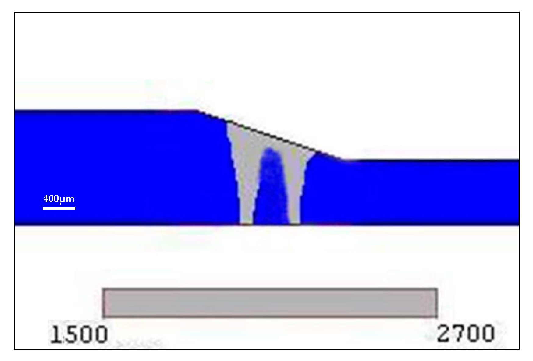
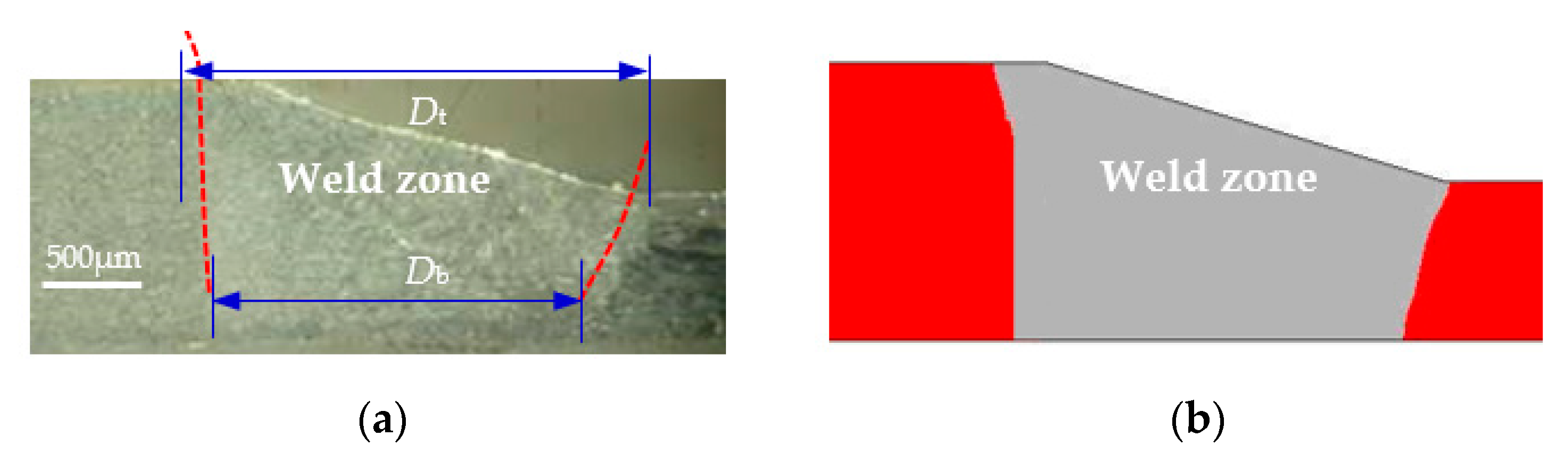
4.1. Model Validation

The mathematical model was validated according to a comparison of the weld cross-section of the calculated result with that of experimental result. The weld width Dt (top surface) and Db (bottom surface) were employed to quantitatively evaluate the calculated result and experimental result. The Dt and Db of the calculated values are 103.3% and 97.5% of the experimental value, respectively. As shown in Figure 7, it can be seen that the simulated result and experimental result display that they are good agreement with each other. Therefore, the mathematical model with the assumptions in present study were all acceptable. The temperature field could be analyzed, and the weld profile could be predicted by the numerical simulation based on the present mathematical model.

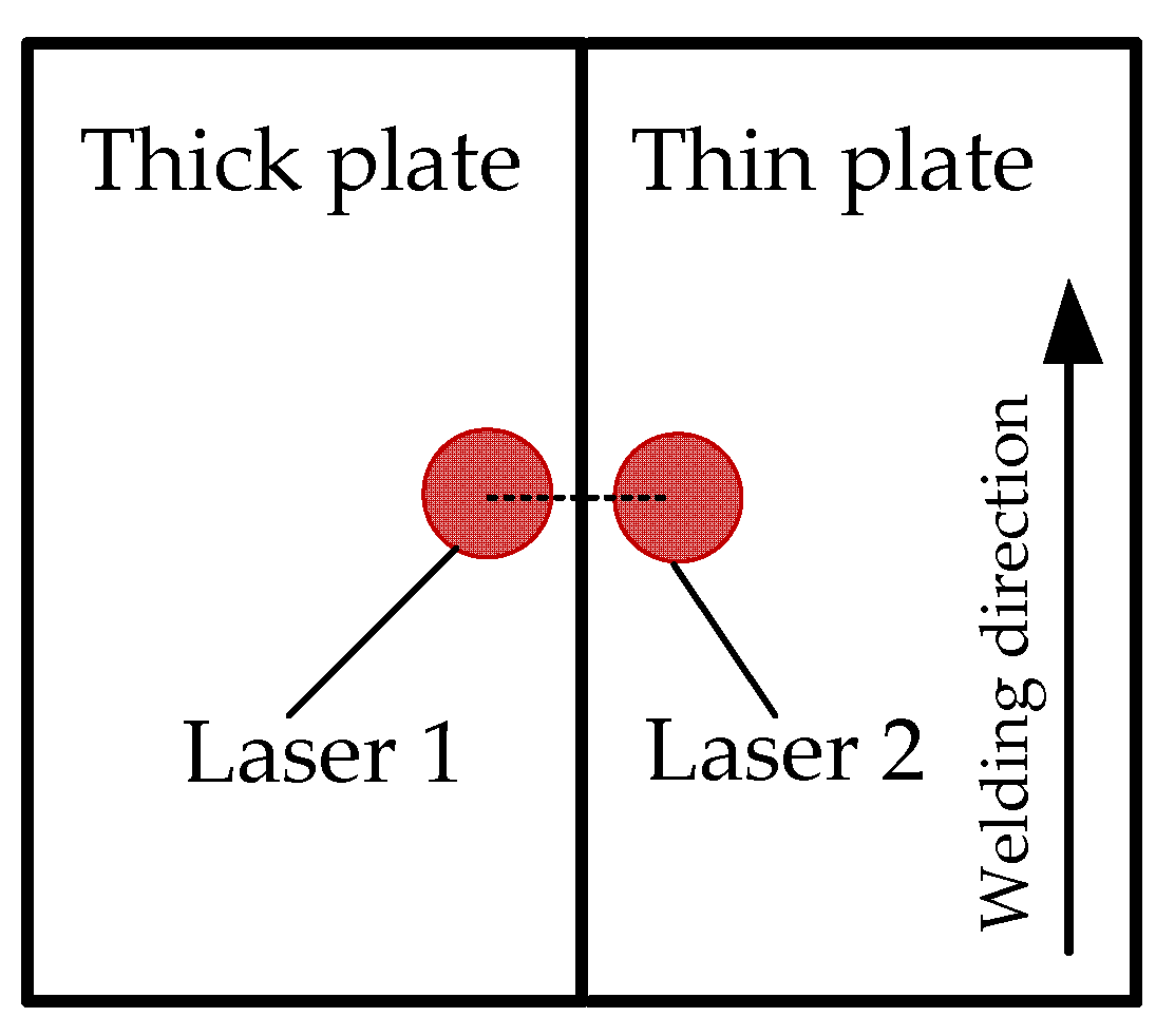
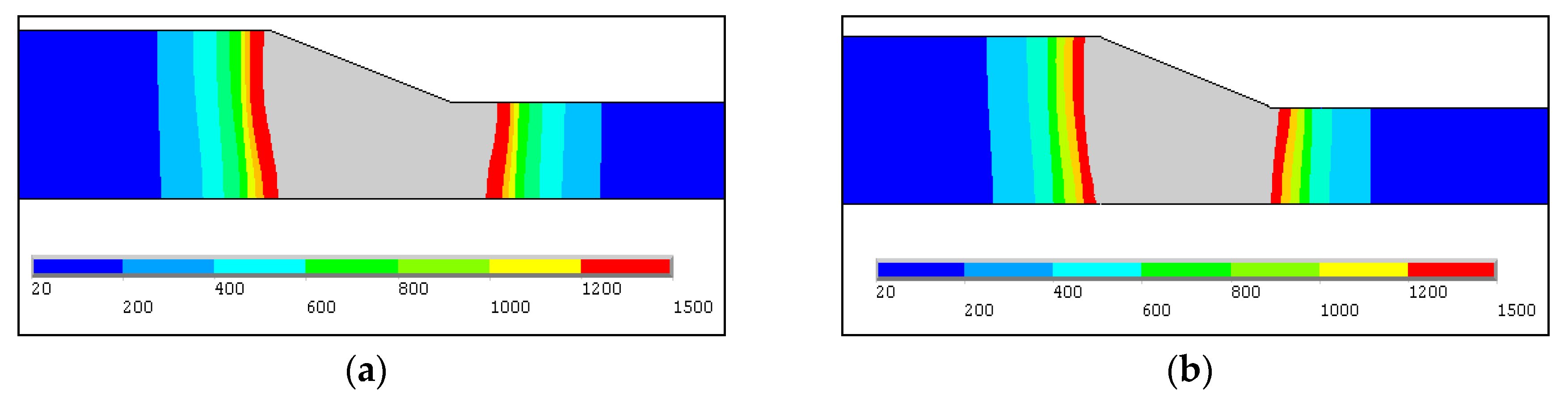
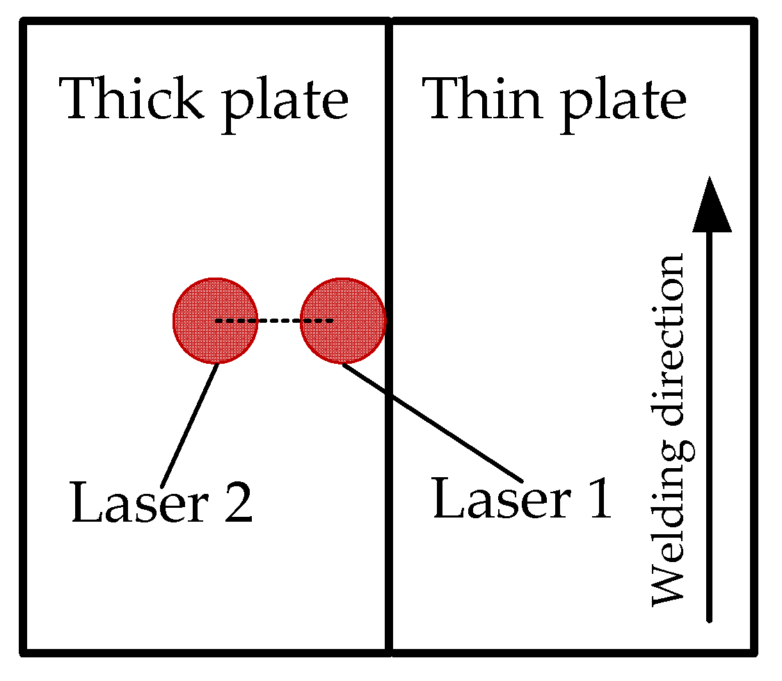
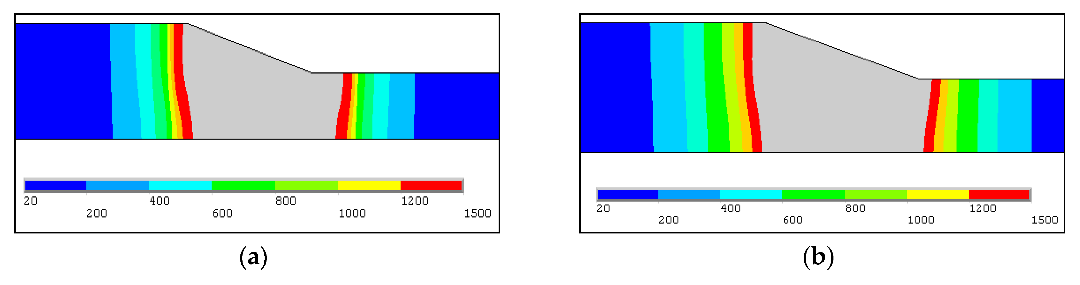
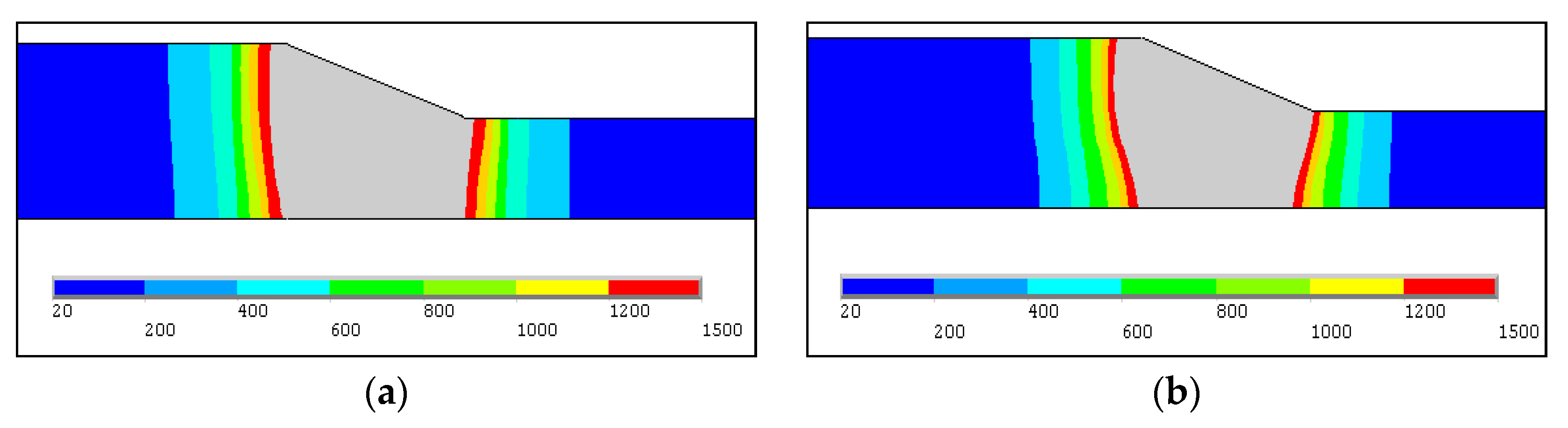
4.2. Optimization of Dual-Beam Laser Arrangement Based on Weld Profile Simulation

During the welding of tailored blanks with different thicknesses, the weld profile must be different from that of the equal thickness, and there is a certain inclination angle on the top surface of the weld because of the difference of the plate thicknesses [28,29]. The mechanical properties of welded joints are directly affected by the width of the weld surface and the transition morphology between thick plate and thin plate. Forsman et al. [30] investigated the formability of laser welded tailored blanks by Erichsen test and found that the smallest weld width on the top surface had the best formability. In addition, the width of the weld surface should also be narrow from the aspects of weld appearance and corrosion resistance properties, so the weld width on the top surface is taken into account as a criterion to evaluate the weld quality. During dual-beam laser welding of tailored blanks, the welding energy was controlled via changing the dual-beam laser arrangement, and then changing weld profile.
While the tailored blanks are conducted using dual-beam laser welding, the arrangement mode I of the dual-beam laser (traverse arrangement), as shown in Figure 8, is usually employed to increase the welding efficiency and gap tolerance [12,21,30]. Namely, as shown in Figure 8, one laser beam irradiates on the thick plate and the other laser beam irradiates on the thin plate, and the line connecting focused spot centers of the dual-beam laser is perpendicular to the welding direction. Figure 9 shows the calculated weld cross-section of tailored blanks with the dual-beam laser arrangement mode I and different dual-beam laser power ratio (Plaser 1/Plaser 2). The calculated results indicate that the weld width on the top surface gained by 1:1 power ratio of dual-beam laser is evidently bigger than that of the 2:1 power ratio. This is because when the power ratio of the dual-beam laser was 1:1, the heating effect on the thin plate would be more than that on the thick plate, so more metal in the thin plate was melted to form the weld, which would inevitably result in the distinct increase of the weld width of tailored blanks.
In order to decrease the weld width of dual-beam laser welded tailored blanks, the arrangement mode II of dual-beam laser indicated in Figure 10 was considered to be used and compared with that of the arrangement mode I. For the arrangement mode II, dual-beam lasers all irradiate on the thick plate, and the line connecting focused spot centers of the dual-beam laser is perpendicular to the welding direction. Figure 11 shows the calculated weld cross-section of tailored blanks with different arrangement modes and the same 1:1 power ratio of dual-beam laser. The weld width on top surface achieved by dual-beam laser arrangement mode I is larger than that of dual-beam laser arrangement mode II. While dual-beam laser power ratio was 1:1 and the irradiated position of laser 1 was fixed, there must be more metal of the thin plate to be melted than that of the thick plate when the laser 2 irradiated on the thin plates, and thus the weld width increased. While the dual-beam laser power ratio increased to be 2:1, the calculated results as shown in Figure 12 clearly display that the weld width achieved by dual-beam laser arrangement mode I was also larger than that by dual-beam laser arrangement mode II. Therefore, the dual-beam laser arrangement mode II is more suitable for reducing the weld width compared with the dual-beam laser arrangement mode I. In addition, the greater the power ratio of dual-beam laser (Plaser 1/Plaser 2), the narrower the weld width was, as shown in Figure 11b and Figure 12b. However, for dual-beam laser arrangement mode II, because dual-beam lasers all irradiate on the thick plate and the focused spots of dual-beam laser were all very small, there was lower tolerance to gap between the tailored blanks compared with the dual-beam laser arrangement mode I [12].
In order to both reduce the weld width and improve the gap tolerance, the dual-beam laser arrangement mode III as shown in Figure 13 was designed to weld tailored blanks. For the dual-beam laser arrangement mode III, one laser beam irradiates on the thick plate and the other laser beam on the thin plate, and the line connecting the dual-beam laser focused spot centers inclines to the welding direction at an angle of 45°. The calculated weld cross-section of the tailored blanks cross-section with the different dual-beam laser arrangement mode and the same 2:1 power ratio (Plaser 1/Plaser 2 = 2:1) are presented in Figure 14. It was found that the weld width on top surface decreased 16.7% with the dual-beam laser arrangement mode III compared with the arrangement mode II, and this was because the effective heating width W, as shown in Figure 14, was smaller than that of dual -beam laser arrangement mode II, which caused a wide decrease of the heating zone. However, it is important to note that the angle between the line connecting dual-beam laser focused spot centers and the welding direction cannot be too small, otherwise, the advantages of the good gap tolerance for dual-beam laser welding technology will not be brought into play. Therefore, in this study, considering the weld width and the gap tolerance, the dual-beam laser arrangement mode III and 2:1 power ratio (Plaser 1/Plaser 2) are a relatively optimized process.

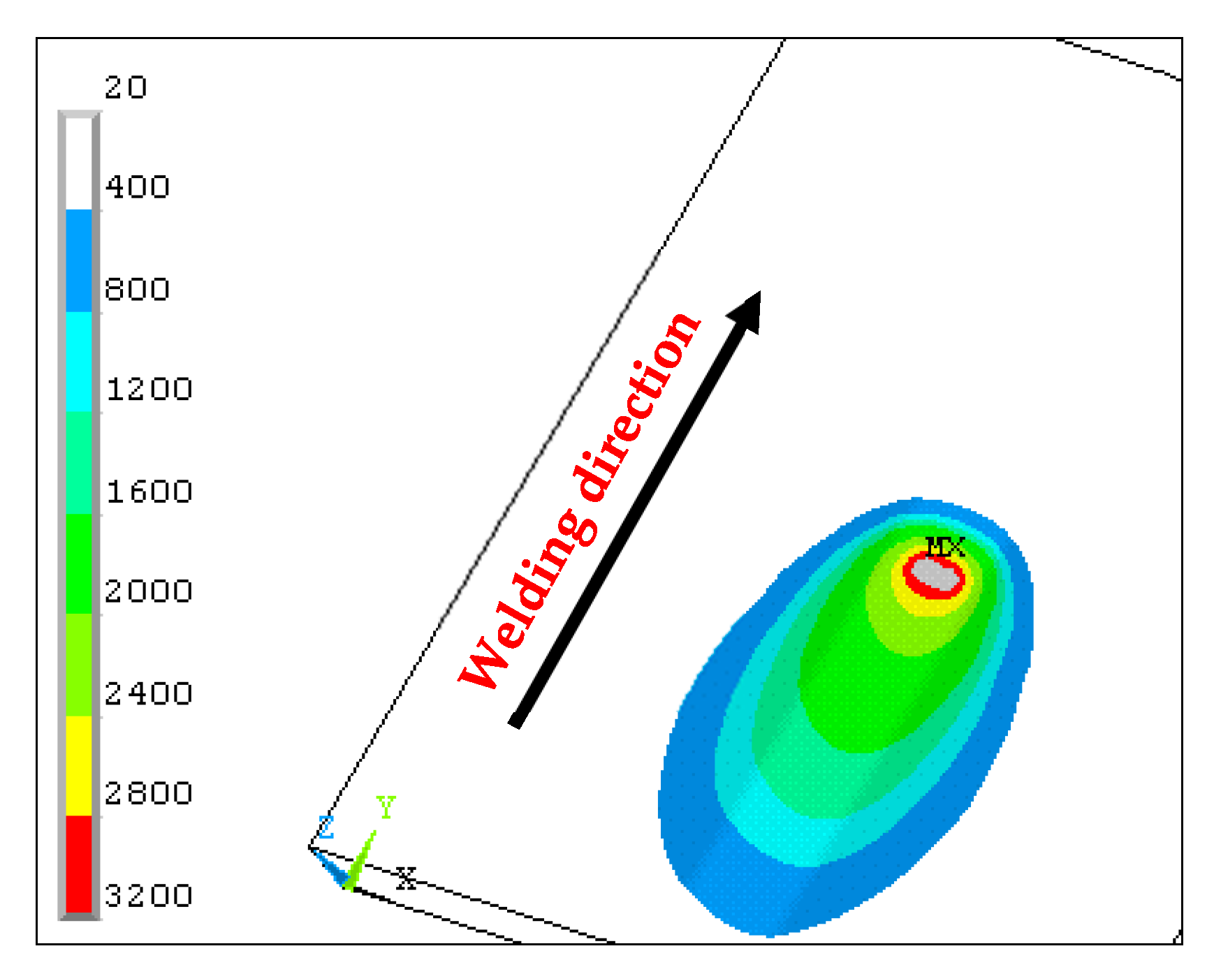
4.3. Temperature Field Characteristic

Due to the unique heat transfer mechanism of dual-beam laser welding process and different thicknesses of tailored blanks, the distribution of temperature field had its own characteristics and should be obviously different from that of the common welding process.
While the dual-beam laser with 1800 W total power and 2:1 power ratio was focused, respectively, on the thick plate and thin plate as showed in Figure 13, meanwhile the welding speed was 1.2 m/min. The contour of transient temperature field on the top surface of tailored blanks during dual-beam laser welding process was given in Figure 15. It can be seen that the fusion zone and heat affected zone are all narrow, owing to the small heating zone with the high-power laser and high welding speed. Figure 15 also indicates that the opening of keyhole is expanded, which helps the plasma ejection from the keyhole, and then provides the stable welding process and high weld quality [31,32]. Figure 16 shows the cross-section of tailored blanks and the gray area is the keyhole shape by numerical calculation. The calculated result of the keyholes shape in this paper are good agreement with that of Hu et al. [19,20]. It clearly displays that two separate keyholes converged together at the top opening, and the size of keyhole tends to get smaller from top to bottom, which is caused by gradual attenuation of laser power due to the inverse toughening absorption of laser by plasma in the keyholes.
Figure 17 indicates the calculated thermal cycle of a point (on top surface) in the tailored line between the thick plate and thin plate. The results demonstrated that the temperature rose quite quickly, and it could reach more than 3300 °C in an instant when there was laser heat source during dual-beam laser welding of tailored blanks. The cooling rate was very fast, which got to 104 °C/s order of magnitude. On the one hand, the thermal conductivity of steel was small, so the heat generated by the laser transmits slowly around the motel pool; on the other hand, it is determined by the characteristics of the laser high energy concentration, fast welding speed and low line energy. However, owing to the increase of the heated zone and weld pool, the cooling rate was obviously lower than that of single beam laser welding [16], which was favorable to reduce welding porosity defect and weld delayed crack. Figure 18 presents the temperature distributions perpendicular to the welding direction in three typical positions. It clearly indicated that the temperature of the laser heating area was very high, which was up to 3500 °C in the dual-beam laser irradiated position. Along the X axis direction, the temperature dropped rapidly near the heating zone and the high temperature region was narrow. Moreover, because of the dual-beam laser welding, there were two temperature peak points in weld pool zone. Behind the heat source, the temperature decreased obviously, and the width of weld pool increased. The region above liquidus temperature for the thin plate was evidently larger than that for the thick plate, which meant that the weld width of thin plate was greater than that of thick plate. In contrast to Figure 17 and Figure 18, the peak temperature points were not on the center of the weld pool, but on the dual-beam laser irradiated positions.
To sum up, above all, the weld width can be mainly controlled by the laser acting on the thin plate based on temperature field distribution, and compared with single beam laser welding, the dual-beam laser welding of tailored blanks has great advantages on improving the heat transfer, temperature field and weld profile during the welding process, which results in reducing welding defects and enhancing welding quality.

5. Conclusions

In the present investigation, a three-dimensional mathematical model has been put forward to analyze and optimize dual-beam laser welding process for tailored blanks with different thicknesses. The main conclusions are presented as follows:
(1)
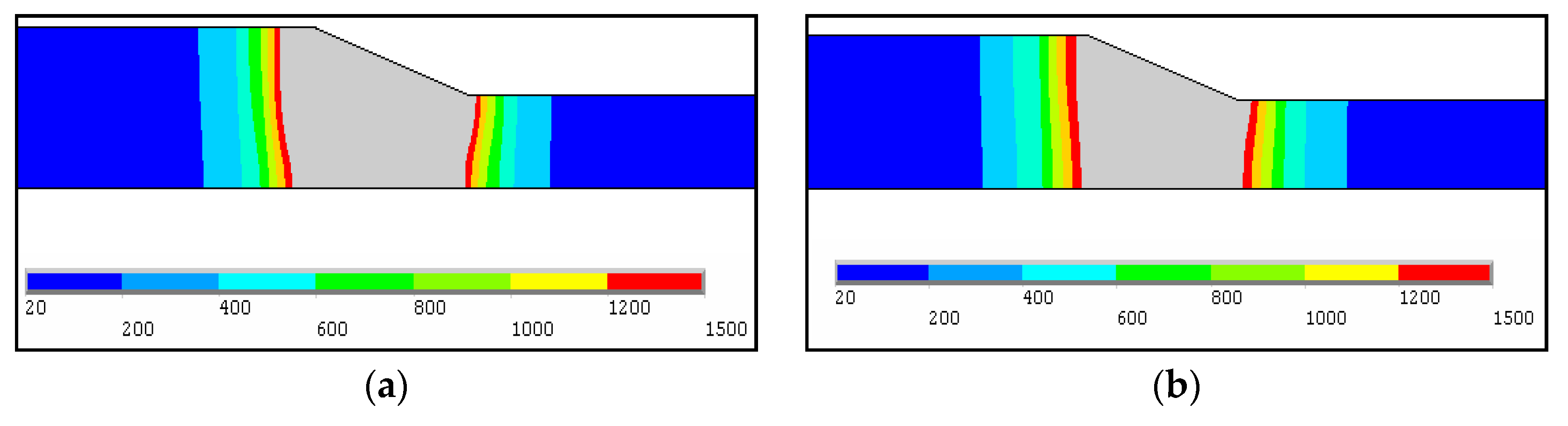
A hybrid heat source model consisted of one surface heat source and double body heat sources was established, namely, the plasma above the workpiece was considered by a surface heat source and heat transfer of double keyholes in the weld pool was simulated by two cylindrical heat sources. Based on the consideration of the temperature dependence of material physical properties, convection and radiation heat transfer, and latent heat of the material, the finite element model for numerical simulation of temperature field was developed by assuming and simplifying the model. When comparing the weld cross-section, the calculated result displayed a good agreement with the experimental result.
(2)
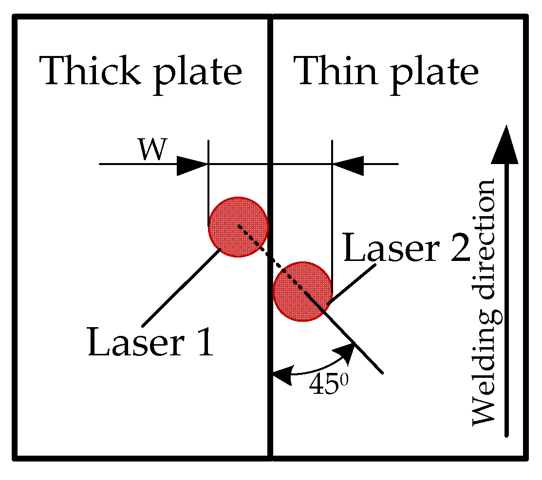
While the weld width on the top surface and gap tolerance were taken into account as evaluating criterion, the arrangement mode of dual-beam laser that one laser beam irradiated on the thick plate and the other laser beam on the thin plate, and the line connecting the dual-beam laser focused spot centers inclines to the welding direction at an angle of 45°, with 2:1 power ratio was the preferable process for dual-beam laser welding of tailored blanks with different thicknesses.
(3)
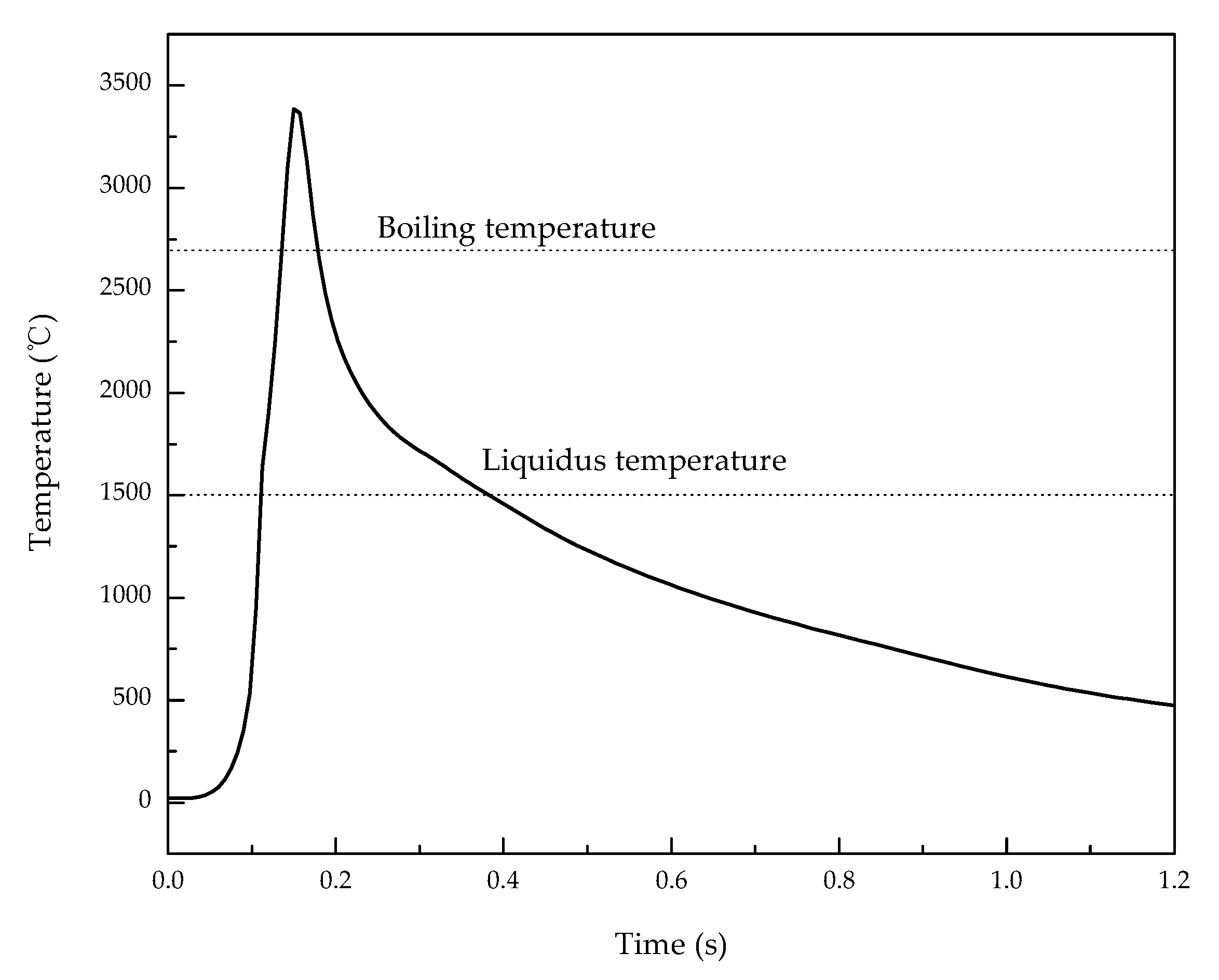
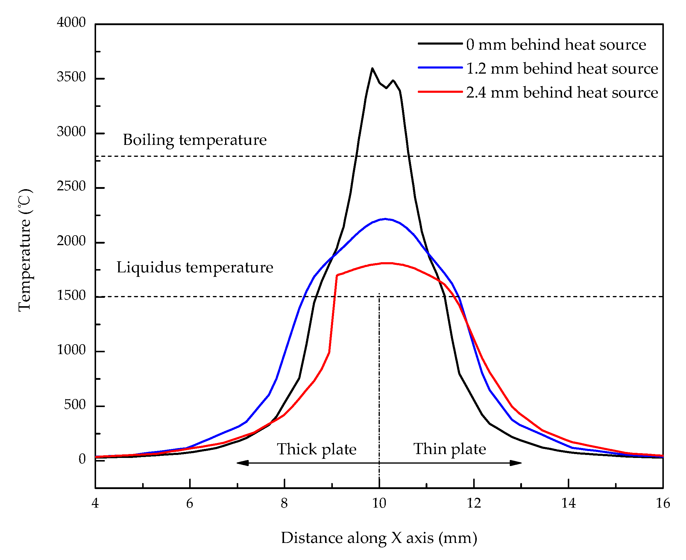
The opening of keyhole was expanded, which helps the plasma ejection from the keyhole, and although the cooling rate was very fast, it was obviously lower than that of single beam laser welding, which was favorable to reduce welding defects and improve weld quality. The peak temperature points were not located on the center of the weld pool, but on dual-beam laser irradiated positions. The weld width can be mainly controlled by the laser acting on the thin plate based on the temperature field distribution during dual-beam laser welding of tailored blanks.

Author Contributions

Writing—original draft, investigation and funding acquisition: X.Z. (Xinge Zhang); methodology: L.L.; conceptualization, Y.C.; formal analysis: X.Z. (Xiaocui Zhu); data curation: S.J.

Funding

The research was financially supported by the Jilin Scientific and Technological Development Program (20160520055JH).

Acknowledgments

The work was supported by the program for the JLU Science and Technology Innovative Research Team (JLUSTIRT).

Conflicts of Interest

The authors declare no conflict of interest.

References

  1. Song, Y.; Yu, C.; Yu, H.; Zhao, C. Mechanical properties improvement of laser tailor welded blanks of DP600 steel by magnetic treatment. Metals 2017, 7, 85. [Google Scholar] [CrossRef]
  2. Yun, J.-G.; Lee, J.-H.; Kwak, S.-Y.; Kang, C.-Y. Study on the formation of reaction phase to Si addition in boron steel Hot-Dipped in Al–7Ni Alloy. Coatings 2017, 7, 186. [Google Scholar] [CrossRef]
  3. Chan, S.M.; Chan, L.C.; Lee, T.C. Tailor-welded blanks of different thickness ratios effects on forming limit diagrams. J. Mater. Process. Technol. 2003, 132, 95–101. [Google Scholar] [CrossRef]
  4. Min, K.B.; Kim, K.S.; Kang, S.S. A study on resistance welding in steel sheets using a tailor-welded blank (1st report) evaluation of upset weldability and formability. J. Mater. Process. Technol. 2000, 101, 186–192. [Google Scholar] [CrossRef]
  5. Davies, R.W.; Grant, G.J.; Eddie Oliver, H.; Khaleel, M.A.; Smith, M.T. Forming-limit diagrams of aluminum tailor-welded blank weld material. Metall. Mater. Trans. A 2001, 32, 275–283. [Google Scholar] [CrossRef]
  6. Shakeri, H.R.; Buste, A.; Worswick, M.J.; Clarke, J.A.; Feng, F.; Jain, M.; Finn, M. Study of damage initiation and fracture in aluminum tailor welded blanks made via different welding techniques. J. Light Met. 2002, 2, 95–110. [Google Scholar] [CrossRef]
  7. Zadpoor, A.A.; Sinke, J.; Benedictus, R. Mechanics of tailor welded blanks: an overview. Key Eng. Mater. 2007, 344, 373–382. [Google Scholar] [CrossRef]
  8. Staud, D.; Merklein, M.; Fratini, L.; Buffa, G. Investigations on the mechanical properties and formability of friction stir welded and laser welded aluminum tailored blanks. Key Eng. Mater. 2007, 344, 143–150. [Google Scholar]
  9. Anand, D.; Chen, D.L.; Bhole, S.D.; Andreychuck, P.; Boudreau, G. Fatigue behavior of tailor (laser)-welded blanks for automotive applications. Mater. Sci. Eng. A 2006, 420, 199–207. [Google Scholar] [CrossRef]
  10. Farabi, N.; Chen, D.L.; Li, J.; Zhou, Y.; Dong, S.J. Microstructure and mechanical properties of laser welded DP600 steel joints. Mater. Sci. Eng. A 2010, 527, 1215–1222. [Google Scholar] [CrossRef]
  11. Merklein, M.; Johannes, M.; Lechner, M.; Kuppert, A. A review on tailored blanks—production, applications and evaluation. J. Mater. Process. Technol. 2014, 214, 151–164. [Google Scholar] [CrossRef]
  12. Hsu, R.; Engler, A.; Heinemann, S. The gap bridging capability in laser tailored blank welding. In Proceedings of the 17th International Congress on Application of Lasers and Electro-Optics (ICALEO’98), Orlando, FL, USA, 16–19 November 1998; pp. 224–231. [Google Scholar]
  13. Swif-Hook, D.T.; Gick, A.E.F. Penetration welding with lasers—Analytical study indicates that present laser beam welding capabilities may be extended tenfold. Weld. J. 1973, 52, 492–499. [Google Scholar]
  14. Steen, W.M.; Dowden, J.; Davis, M.; Kapadia, P. A point and line source model of laser keyhole welding. J. Phys. D Appl. Phys. 1998, 21, 1255–1260. [Google Scholar] [CrossRef]
  15. Kazemi, K.; Goldak, J.A. Numerical simulation of laser penetration welding. Comp. Mater. Sci. 2009, 44, 841–849. [Google Scholar] [CrossRef]
  16. Shanmugam, N.S.; Buvanashekaran, G.; Sankaranarayanasamy, K.; Kumarc, S.R. A transient finite element simulation of the temperature and bead profiles of T-joint laser welds. Mater. Des. 2010, 31, 4528–4542. [Google Scholar] [CrossRef]
  17. Yu, S.R.; Xiong, J.H.; Fan, D.; Chen, J.H. Numerical simulation on temperature field in laser welding of thin aluminum alloy plate with different thickness. Trans. China Weld. Inst. 2007, 28, 17–20. [Google Scholar]
  18. Yu, S.R.; Fan, D.; Xiong, J.H. Numerical simulation on stress-strain field of laser welding aluminum alloy joints with different thickness. Trans. China Weld. Inst. 2008, 29, 25–28. [Google Scholar]
  19. Hu, J.; Tsai, H.L. Fluid flow and weld pool dynamics in dual-beam laser keyhole welding. In Proceedings of the 2003 ASME International Mechanical Engineering Congress & Exposition (IMECE’03), Washington, DC, USA, 16–21 November 2003. IMECE2003-41711. [Google Scholar]
  20. Hu, J.; Tsai, H.L.; Lee, Y.K. Modeling of weld pool dynamics during dual-beam laser welding process. In Proceedings of the 22th International Congress on Application of Lasers and Electro-Optics (ICALEO’03), Jacksonville, FL, USA, 13–16 October 2003; p. 1009. [Google Scholar]
  21. Zhou, J.; Tsai, H.L. Investigation of fluid flow and heat transfer in 3-D dual-beam laser keyhole welding. In Proceedings of the ASME 2010 International Manufacturing Science and Engineering Conference, Erie, PA, USA, 12–15 October 2010; pp. 247–254. [Google Scholar]
  22. Hou, C.A. Finite element simulation of dual-beam laser welding using ANSYS. In Proceedings of the Conference of the International Association for the Study of Traditional Environments, Pittsburgh, PA, USA, 15–18 May 1994; pp. 430–433. [Google Scholar]
  23. Liu, Y.N.; Kannatey-Asibu, E. Finite Element Analysis of heat flow in dual-beam laser welded tailored blanks. J. Manuf. Sci. Eng. 1998, 120, 272–278. [Google Scholar] [CrossRef]
  24. Solana, P.; Ocaña, J.L. A mathematical model for penetration laser welding as a free-boundary problem. J. Phys. D Appl. Phys. 1997, 30, 1300–1313. [Google Scholar] [CrossRef]
  25. Feng, X.S. The Analysis of Temperature Field and Stress-Strain Field in Laser Welding of Titanium Alloy T-Joint. Master’s Thesis, Harbin Institute of Technology, Harbin, China, July 2003. [Google Scholar]
  26. Deng, D.; Murakawa, H. Numerical simulation of temperature field and residual stress in multi-pass welds in stainless steel pipe and comparison with experimental measurements. Comp. Mater. Sci. 2006, 37, 269–277. [Google Scholar] [CrossRef]
  27. Zain-ul-abdein, M.; Nélias, D.; Jullien, J.F.; Boitout, F.; Dischert, L.; Noe, X. Finite element analysis of metallurgical phase transformations in AA 6056-t4 and their effects upon the residual stress and distortion states of a laser welded t-joint. Int. J. Pres. Ves. Pip. 2011, 88, 45–56. [Google Scholar] [CrossRef]
  28. Lamprecht, K.; Geiger, M. Experimental and numerical investigation of the formability of laser welded patchwork blanks. Adv. Mater. Res. 2005, 6, 689–696. [Google Scholar] [CrossRef]
  29. Qiu, X.G.; Chen, W.L. The study of numerical simulation on the laser tailor welded blanks stamping. J. Mater. Process. Technol. 2007, 187, 128–131. [Google Scholar] [CrossRef]
  30. Forsman, T.; Sweden, S. Laser welding of tailored blanks. In Proceedings of the 21th International Congress on Application of Lasers and Electro-Optics (ICALEO’02), Scottsdale, AZ, USA, 14–17 October 2002; pp. 956–960. [Google Scholar]
  31. Cho, W.I.; Na, S.J.; Thomy, C.; Vollertsen, F. Numerical simulation of molten pool dynamics in high power disk laser welding. J. Mater. Process. Technol. 2012, 212, 262–275. [Google Scholar] [CrossRef]
  32. Deutsh, M.G.; Punkari, A.; Weckman, D.C.; Kerr, H.W. Weldability of 1.6 mm thick aluminium alloy 5182 sheet by single and dual beam Nd:YAG laser welding. Sci. Technol. Weld. Joi. 2003, 8, 246–256. [Google Scholar] [CrossRef]
Figure 1. Schematic diagram of dual-beam laser welding of tailored blanks with different thicknesses.
Metals 09 00135 g001
Figure 2. Dual-beam laser welding of tailored blanks with different thicknesses: (a) Schematic diagram; (b) cross-section of tailored blanks welded joint.
Metals 09 00135 g002
Figure 3. Gaussian distribution of heat flux for surface heat source.
Metals 09 00135 g003
Figure 4. Distribution of heat flux for body heat source.
Metals 09 00135 g004
Figure 5. (a) Geometric model; (b) overall schematic diagram of mesh; (c) mesh of X-Z plane; (d) mesh of X-Y plane.
Metals 09 00135 g005
Figure 6. The material physical properties vary with temperature: (a) Thermal conductivity coefficient; (b) specific heat.
Metals 09 00135 g006
Figure 7. Comparison of weld cross-section: (a) Experimental result; (b) calculated result.
Metals 09 00135 g007
Figure 8. The arrangement mode I of dual-beam laser: one laser beam irradiates on the thick plate and the other laser beam on the thin plate. The line connecting the dual-beam laser focused spot centers is perpendicular to the welding direction.
Metals 09 00135 g008
Figure 9. The calculated weld cross-section of tailored blanks cross-section (Arrangement mode I, 1800 W total power, and 1.2 m/min welding speed): (a) 1:1 power ratio; (b) 2:1 power ratio.
Metals 09 00135 g009
Figure 10. The arrangement mode II of dual-beam laser: dual-beam lasers all irradiate on the thick plate, and the line connecting the dual-beam laser focused spot centers is perpendicular to the welding direction.
Metals 09 00135 g010
Figure 11. The calculated weld cross-section of tailored blanks cross-section (1:1 power ratio,1800 W total power, and 1.2 m/min welding speed): (a) The arrangement mode I; (b) the arrangement mode II.
Metals 09 00135 g011
Figure 12. The calculated weld cross-section of tailored blanks cross-section (2:1 power ratio,1800 W total power, and 1.2 m/min welding speed): (a) The arrangement mode I; (b) the arrangement mode II.
Metals 09 00135 g012
Figure 13. The arrangement mode III of dual-beam laser: one laser beam irradiates on the thick plate and the other laser beam on the thin plate. The line connecting the dual-beam laser focused spot centers inclines to the welding direction at an angle of 45°.
Metals 09 00135 g013
Figure 14. The calculated weld cross-section of the tailored blanks cross-section (2:1 power ratio, 1800 W total power, and 1.2 m/min welding speed): (a) The arrangement mode II (b) the arrangement mode III.
Metals 09 00135 g014
Figure 15. Contour of transient temperature field on top surface of tailored blanks.
Metals 09 00135 g015
Figure 16. The cross-section of keyholes during dual-beam laser welding of tailored blanks.
Metals 09 00135 g016
Figure 17. Calculated thermal cycle of a point in the tailored line between thick plate and thin plate.
Metals 09 00135 g017
Figure 18. Temperature distribution perpendicular to the welding direction.
Metals 09 00135 g018
Table 1. Chemical compositions of steel plate (wt.%).
ComponentCMnSiSPFe
wt.%0.090.300.250.030.02Balance
Table 2. The physical properties parameters of the base material.
Density kg/m3Solidus Temperature °CLiquidus Temperature °CBoiling Temperature °CMelting Latent Heat J/kg
77781460150027002.5 × 105

