Article

Effect of Heat Treatment on the Microstructure and Properties of Ultrafine WC–Co Cemented Carbide

1
College of Materials Science and Engineering, Fuzhou University, Fuzhou 350116, China
2
Xiamen Tungsten Co., LTD. Technology Center, Xiamen 361009, China
3
College of Materials Science and Engineering, Fujian University of Technology, Fuzhou 350118, China
4
Fujian Provincial Key Laboratory of New Material Preparation and Forming Technology, Fuzhou 350118, China
*
Author to whom correspondence should be addressed.
Metals 2019, 9(12), 1302; https://doi.org/10.3390/met9121302
Submission received: 15 October 2019 / Revised: 27 November 2019 / Accepted: 30 November 2019 / Published: 3 December 2019

Abstract

:
In this paper, the effect of heat treatment on the microstructure and properties of a 0.8 μm WC–10%Co ultrafine cemented carbide was studied. The results show that the microstructural differences in ultrafine WC–Co cemented carbides without and with heat treatment are mainly reflected in the Co phase. For conventional cemented carbides, the hardness and wear resistance can be increased only at the expense of the toughness and strength. An ultrafine-grained WC–Co cemented carbide with good hardness and toughness can be obtained by strengthening the Co phase through an appropriate heat treatment process, and the service life of the ultrafine-grained WC–Co cemented carbide can be improved under actual cutting conditions.

1. Introduction

In WC–Co cemented carbides, the Co binder phase bridges the framework of the hard phase. The structure of the Co phase plays an important role in the strength and toughness of cemented carbides. As early as the 1940s, scholars began to study the heat treatment of cemented carbides [1,2,3,4,5]. The focus of research has mainly been on the effect heat treatment has on the texture of the Co phase and the changes in the cemented carbide properties. Between the 1960s and 1980s, extensive investigations on the mechanism of the precipitation of intermetallic phases from W-supersaturated Co binder in hardmetals [2,3,4,5] were conducted by annealing experiments. The most detailed work reported on phase transformations in Co–W–C alloys was carried out by Jonsson and Aronsson [2]. This work was carried out on Co–W–C alloys which simulated a range of binder phase compositions with varying W and C contents. Combined transmission electron microscopy and X-ray diffraction showed that a whole range of transformation products could arise depending upon the alloy composition and the ageing temperature. Jonsson [3,4] followed-up on the previous work on simulated binder phase alloys and showed by transmission electron microscopy that similar precipitation reactions also occur in the binder phase of aged cemented carbides. Depending on the annealing temperature, different shapes of these precipitations, not all of which could be characterized structurally, were reported: coherent precipitations of 3–5 nm were formed at 550–600 °C, coherent precipitations of 15 nm, partially grown to lamellae at 650 °C; coherent precipitations (30 nm) in the form of lamellae, plates, and Co3W formed at 700 °C and at 750 °C, lamellae and plate-shaped Co3W. Since then, cemented carbides have been successfully applied in industrial production. Heat-treated cemented carbides are used for steel-bonded carbides, hard mining alloys, cutting tool materials, and composite materials [6,7,8,9,10,11,12,13].
The dissolution and precipitation of WC in the Co phase always occurs during the sintering process which can change the structure and composition of the binder phase [14]. The calculation of the W–Co–C ternary phase diagram has shown that the solubility of WC in the Co phase increases with increasing temperature [15,16,17]. The fact that the solubility of tungsten carbide decreases with decreasing temperature provides a basis for changing the properties of WC–Co alloys by heat treatment [18]. Studies [18,19,20] show that the solid solubility of W in the Co phase can be increased through an appropriate heat treatment process which leads to the strengthening of the Co phase. The dissolution of W and C in the Co phase increases the stacking fault energy and martensitic transformation temperature, inhibits the martensitic transformation, and stabilizes the cobalt phase with a face-centered cubic crystal structure (fcc Co phase) which increases the toughness of the cemented carbide [14,18]. These studies clarified the basic principle of heat treatment on cemented carbide strengthening and promoted the application of heat treatment of cemented carbides.
Until now, the successful application of heat treatments has mainly focused on medium coarse-grained and coarse-grained cemented carbides which are used as mining and engineering tool materials. Research on the heat treatment and mechanical properties of a WC–8.4%Co coarse-grained cemented carbide showed that the hardness of the binder phase was improved by heat treatment which resulted in an improvement in the overall hardness of the alloy [21]. In the investigation of oil bath quenching of a YG11 cemented carbide, it was observed that the transverse rupture strength (TRS) of a YG11 cemented carbide was increased by a rapid cooling process [18]. The residual stress in the YG10 cemented carbide caused by work hardening was eliminated by an appropriate annealing process, and the annealed alloy had excellent thermal stability under high-temperature conditions [22]. Therefore, the hardness, transverse rupture strength, toughness, and thermal stability of cemented carbide can be optimized by an appropriate heat treatment process. However, research on the heat treatment of submicron- and ultrafine-grained cemented carbides is still very limited. In this paper, a 0.8 μm WC-10%Co ultrafine-grained cemented carbide was prepared by vacuum sintering. The effects of the heat treatment process on the microstructure, properties, and performance of the ultrafine-grained cemented carbide were studied, and the findings provide a reference for the performance optimization of ultrafine-grained WC–Co cemented carbide materials.

2. Experimental Methods

In the present study, a WC-10%Co ultrafine-grained cemented carbide with a WC particle size of 0.8 μm and a nominal cobalt content of 10% was prepared by vacuum sintering. The grain inhibitor of the cemented carbide comprised Cr3C2 with a content of 0.6%. The experimental samples were sintered in a PVSGgr 20/20 vacuum sintering furnace (Shimadzu, Kyoto, Japan). The sintering temperature was 1420 °C with a holding time of 1 h, and the cooling rate was 5 °C/min during the cooling process to prepare the conventional alloy. The specific heat treatment process was as follows. The sample was sintered at 1420 °C with a holding time of 1 h (mentioned previously), cooled at 5 °C min to 1280 °C, then rapidly cooled to room temperature at a cooling rate of 86 °C/min in the furnace. Then, the samples were annealed at 300 °C, 500 °C, and 800 °C with a holding time of 5 h in a vacuum furnace. The heating rate of the annealing process was 3 °C/min, and the cooling rate was 2 °C/min when the annealing process was finished. A schematic diagram of the sintering and heat treatment processes is shown in Figure 1.
The coercive force (Hc) and magnetic saturation (Ms) of the cemented carbides were measured using a SM-8100/LDJ-702 coercive force and magnetic saturation measurement instrument manufactured by Leco (St. Joseph, MI, USA). The HV30 and KIC of the alloy were determined with a Tukon2100B hardness tester (Instron, Grove City, PA, USA) according to the ISO 28079:2009 standard (Hardmetals—Palmqvist toughness test). The transverse rupture strength (TRS) was measured on polished specimens with dimensions of 6.5 mm × 5.25 mm × 20 mm by a CMT5305 universal testing machine (MTS, Shenzhen, China) according to the ASTM B406 standard (Standard Test Method for Transverse Rupture Strength of Cemented Carbides). Each of the values for HV30, KIC, and TRS were the average of five measure values. The phase of the specimens was detected by X-ray diffraction (XRD) on an X’Pert PRO X-ray diffractometer (PANalytical, Eindhoven, The Netherlands), and Rietveld refinement was utilized to quantitatively determine the content of the fcc Co phase (face-centered cubic crystal structure) and hcp Co phase (hexagonal close-packed crystal structure) in the binder phase of the specimens. The morphology of the alloy was observed with scanning electron microscopy (SEM) on a S-4800 instrument (Hitachi, Tokyo, Japan). The average grain size and size distribution of the alloy were determined by the linear intercept method. The microstructure was observed with transmission electron microscopy (TEM) on a JEM 2100 instrument (JEOL, Tokyo, Japan). The differences in the structure and composition of the alloy were further confirmed by transmission electron microscopy (TEM) and energy dispersion spectroscopy (EDS).

3. Results and Discussion

3.1. Analysis of Conventional Properties

Table 1 shows the conventional properties of alloy samples without and with heat treatment. As shown in Table 1, the effect of heat treatment on the magnetic saturation (Ms) of the ultrafine-grained cemented carbide was small, but the samples treated with rapid cooling from 1280 °C had a higher coercive force (Hc) than that of the other samples. The transverse rupture strength of the alloy was increased by rapid cooling, but the effect of subsequent annealing treatment on the transverse rupture strength of the alloy was not significant. In fact, the transverse rupture strength (TRS) is one of the most important mechanical properties of WC–Co cemented carbides, and it is affected by many factors. When the porosity of an alloy is negligible, the transverse rupture strength mainly depends on the cobalt content, WC particle size distribution, carbon content, other chemical compositions, and microstructure [23,24]. For the effect of heat treatment on the hardness (HV30) of the alloy, rapid cooling improved the hardness of the alloy. However, with increasing annealing temperature, the hardness of the alloy decreased. The fracture toughness (KIC) of the alloy decreased slightly after rapid cooling which may be attributed to an increase in the internal stress of the alloy after rapid cooling treatment. The fracture toughness of the alloy that experienced rapid cooling from 1280 °C and was then annealed at 500 °C was the best among the samples herein. However, when the annealing temperature was increased to 800 °C, the fracture toughness (KIC) of the alloy decreased sharply. This was mainly due to the change of alloy phase at the annealing temperature of 800 °C. The research result of Wirmark [5] indicated that transformation at 750 °C by either quench ageing or direct isothermal transformation resulted in the discontinuous precipitation of lamellar Co3W. Generally, the formation of intermetallic phases (Co3W) in hardmetals decreases the fracture toughness (KIC) of the alloy.

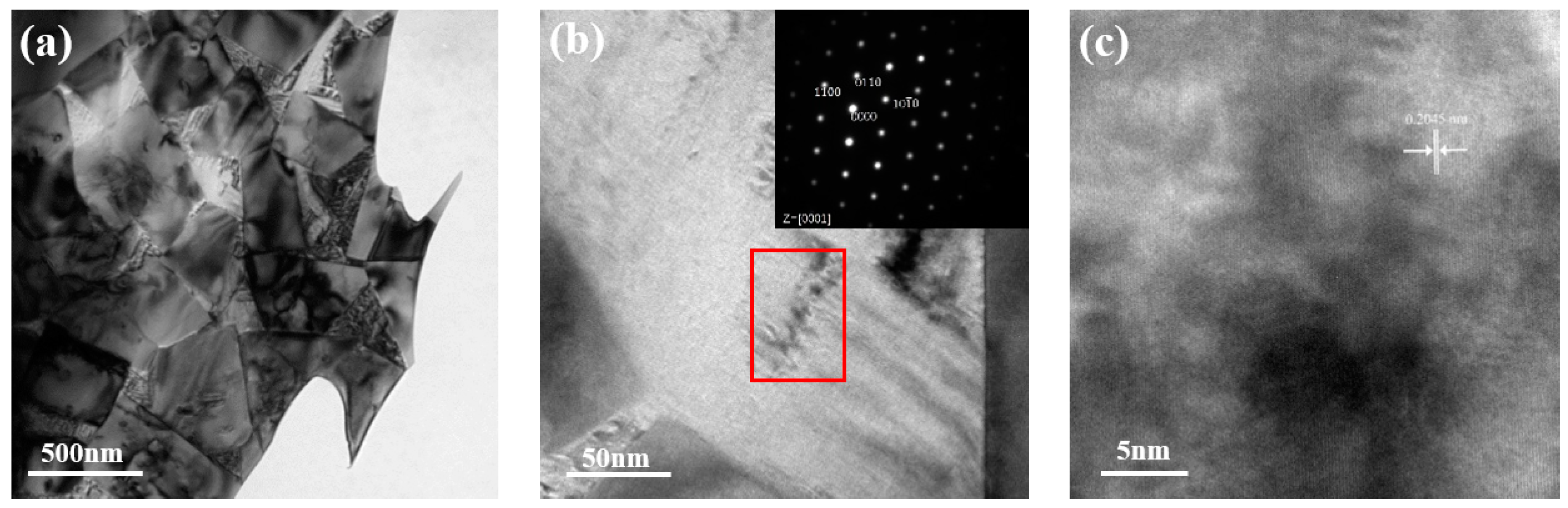
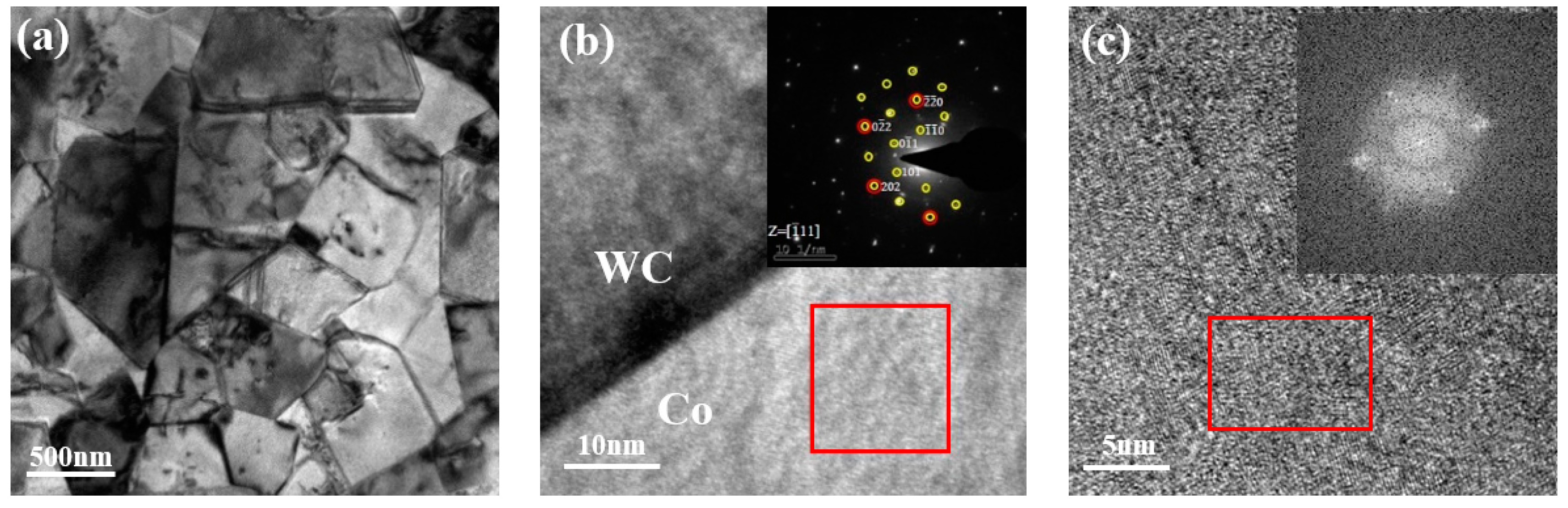
3.2. Effect of Heat Treatment on the Microstructure of Ultra-Fine Cemented Carbide

Figure 2 shows the XRD pattern of the different heat-treated alloys. Table 2 shows the XRD characterization results of the Co phase peak and the resulting Co(hcp)-to-Co(fcc) ratio of the alloy without and with heat treatment. As shown in Figure 2 and Table 2, both the (100) hcp Co and (200) fcc Co peaks shifted to low angles after rapid cooling which indicates that the W content in the Co phase increased, and that the Co phase was strengthened by the solid solution. On the one hand, a solid solution of W in Co can stabilize the fcc Co and inhibit the transformation of the fcc Co to hcp Co. On the other hand, the supersaturated W may precipitate in the Co phase as nanosized particles [25].
Among the two isomers of Co, fcc Co has four slip planes and 12 slip systems, while hcp Co has only one slip plane and three slip systems [26]. Therefore, the higher the content of fcc Co in the binder phase, the better the toughness and transverse rupture strength of the alloy. In addition, fcc Co is metastable at low temperatures, and the martensitic transformation from fcc Co to hcp Co may occur under a sufficient shear stress. This stress-induced martensitic transformation can absorb considerable elastic energy and prevent fracture. Under this mechanism, the higher the content of fcc Co in the binder phase, the higher the transverse rupture strength of cemented carbide. Table 2 shows the results of hcp/fcc Co phase ratio in each alloy sample. As shown in Table 2, the amount of hcp Co in the Co phase of the alloy treated by rapid cooling from 1280 °C tended to decrease, which is consistent with the results indicating an increase in the transverse rupture strength of the alloy that experienced rapid cooling in Table 1. However, it is noteworthy that the alloys that experienced rapid cooling from 1280 °C and were then annealed at 500 °C had the highest KIC value obtained herein and an elevated hcp Co content in the binder phase. Previous studies have shown that an annealing temperature of 500 °C, which is higher than the phase transition temperature of Co at 427 °C, can inhibit the phase transformation of the Co phase [18]. The cooling process after annealing was accompanied by the precipitation of W and C atoms in the Co phase. This precipitation process also led to a phase transformation of the Co phase, and part of the fcc Co phase transformed to hcp Co, resulting in an increase in the hcp Co content in the Co phase. However, since the Co phase did not have fluidity at 500 °C, the precipitated W and C atoms only remained at the dislocation sites inside the Co phase in the form of nanoparticles [2,27], and it was difficult to deposit on the surface of the original WC particles through diffusion; these factors played a role in the dispersion strengthening of the Co phase. When the annealing temperature continued to increase to 800 °C, the KIC of the alloy began to decrease. This is because, at the annealing temperature of 800 °C, the fluidity of the Co phase increased, and the mean free path of the Co phase in the ultrafine-grained cemented carbide decreased. The diffusion of the W and C atoms increased, resulting in an increase in the precipitation of the W and C. On the other hand, during a subsequent slow cooling process, the metastable fcc Co phase formed by rapid cooling was transformed into a stable hcp Co phase at room temperature, and the content of the fcc Co was further reduced in the binder phase.
It was not difficult to see that there were great differences in the microstructure of the Co phase between the alloys without and with the rapid cooling treatment. Therefore, the differences between the two alloys were further confirmed by TEM and EDS analysis. Figure 3 shows the TEM morphology of conventional alloys and the rapidly cooled alloys. Table 3 shows the EDS component analysis results of the areas covered with red dots in Figure 3a,b, where it can be seen that the content of W in the binder phase of the rapidly cooled alloy was higher than that of the conventional alloy which is consistent with the results of the XRD analysis.
The microstructure of the conventional and rapidly cooled alloy was observed by SEM after polishing and etching as shown in Figure 4. The distribution of the WC grain size in 10 randomly taken SEM images under a magnification of 10,000 times was calculated by ImageJ software, and the statistical results are shown in Figure 5. As shown in Figure 4 and Figure 5, the average WC grain size of the conventional alloys was 0.59 μm, and there were a few coarse grains with a size of 2 μm. The average WC grain size of the rapidly cooled alloys was 0.54 μm, and there were no obvious coarse grains. From the TEM morphology of the alloy shown in Figure 3, we can see that the WC grain edges of the conventional alloy were sharp (Figure 3a). After rapid cooling, the WC grain edges became rounded (Figure 3b) which can be explained by the sharp edges of the WC grains preferentially diffusing into the Co phase during the high-temperature heat treatment; the precipitation of the W and C atoms in the Co phase was also suppressed during the rapid cooling process [18]. It is well known that the hardness of cemented carbide has a certain corresponding relationship with the mean free path in the Co phase and WC particle size [28]. With a refinement of the WC grains, the hardness of the alloy increased which corresponds to an increase in the hardness of the alloy after rapid cooling treatment as shown in Table 1.
From the mechanical properties of the alloys treated by different heat treatments in Table 1, the alloy that experienced rapid cooling from 1280 °C and was then annealed at 500 °C had the best comprehensive properties among the samples herein. To explore the differences in the mechanical properties between the conventional alloy and the alloy that was treated with a 1280 °C rapid cooling process + 500 °C anneal, the microstructures of the two kinds of alloys were analyzed by TEM as shown in Figure 6 and Figure 7, respectively.
Figure 6 shows the TEM morphology of the conventional alloy. Figure 6a shows that there are large dark areas within the Co phase. Figure 6b shows the magnified morphology of the Co phase, and the selective electron diffraction (SAED) pattern of the Co phase in the red box is shown in the upper right corner. As shown in the region marked by the red box in Figure 6b, there were regular needle-like precipitates in the Co. Upon combining the TEM images (Figure 6b) and the detailed characterization of Co3W in Reference [27], it was speculated that brittle Co3W were present in the Co phase. According to the literature [29], the precipitation of Co3W in a Co phase can improve the hardness of the alloy, but it reduces the strength and toughness of it. Upon magnifying the structure of the Co phase in Figure 6b, it was found that the lattice of the Co phase was discontinuous in the dark region as shown in Figure 6c.
Figure 7 shows the TEM morphology of the alloy that experienced rapid cooling from 1280 °C and was then annealed at 500 °C. Figure 7a shows that the interface between the WC and Co was clear, and the growth steps of the WC grains can be clearly distinguished. From Figure 7b, it can be seen that there was a very good coherent match at the interface between the WC and Co phases in the alloy, which indicates that the bonding between the WC and Co phases was very good. The SAED analysis of the Co phase showed that there were reflections of the new phase, as shown in the upper right corner of Figure 7b, where the reflections from the new phase are marked with yellow and those from the Co phase are marked with red. As can be seen in Figure 7c, there are many uniformly distributed nanosized particles in the Co phase which correspond to thet “new phase” characterized by SAED analysis. According to the previous analysis, the nanosized particles were W and C atoms that precipitated in the Co phase and did not precipitate on the surface of WC during the rapid cooling and annealing processes. The structures are certainly related to the Co3W phase and are probably a precursor state of the Co3W (named έ by Jonsson and Aronsson [2]). From the research of Wawrzik et al. [30], the formation of the Co3W phase or their fine precursor state (έ) occurs also in industrial samples at significantly shorter annealing times, leaving hardness and TRS unchanged, but increasing the erosion resistance. However, investigations published by Konyashin et al. [27] proved that a dramatically increased combination of hardness, wear-resistance, fracture toughness, and strength of cemented carbides was achieved as a result of the precipitation of extremely fine nanoparticles in the Co binder. In our opinion, the presence of nanosized particles enabled dispersion strengthening of the Co phase which is the reason the material achieved significantly improved combinations of hardness, wear resistance, and fracture toughness (as shown in Table 1).

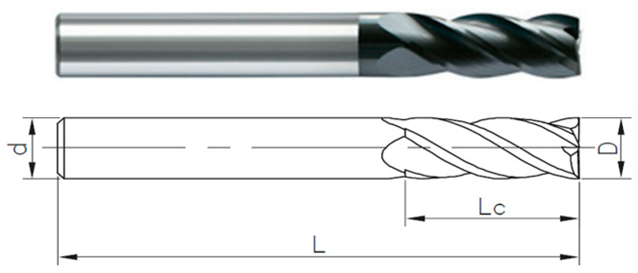
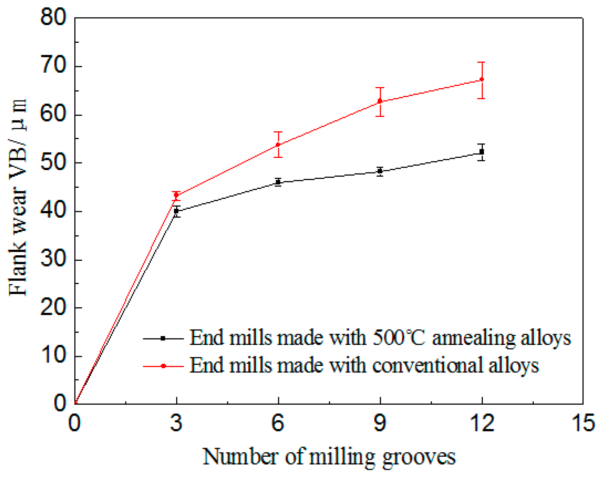
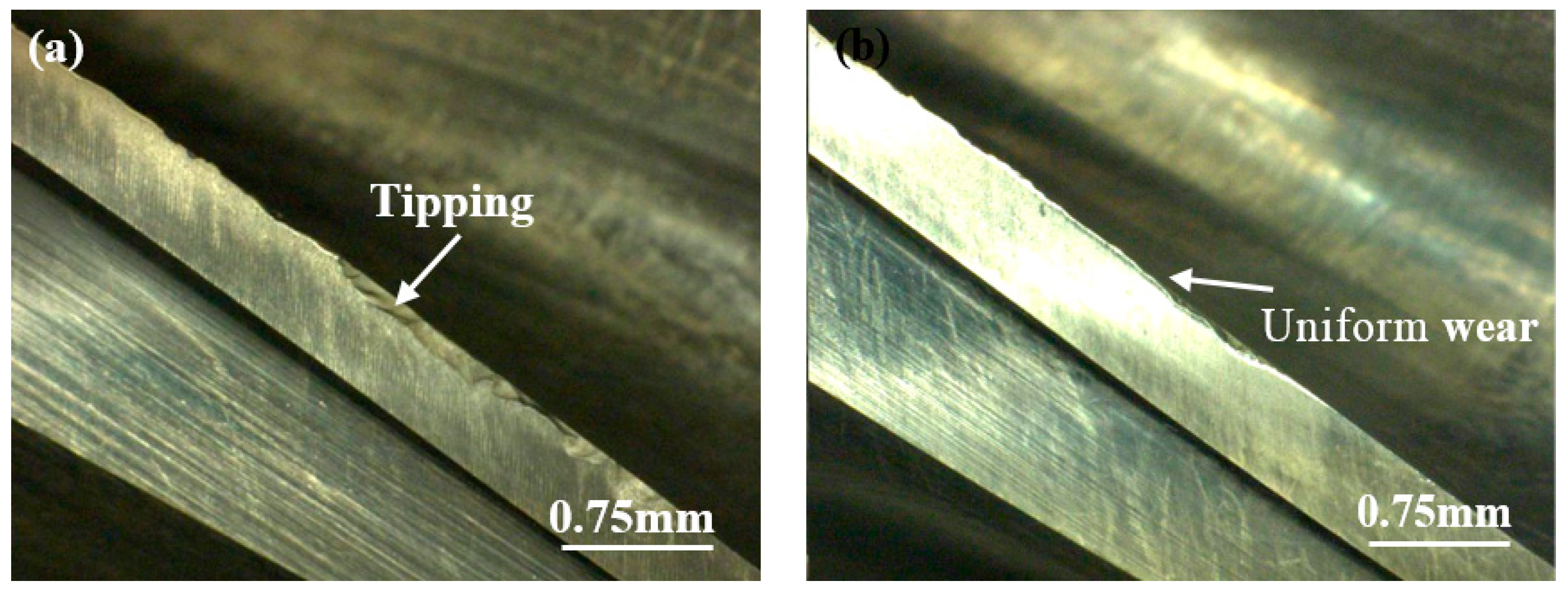
3.3. Cutting Experiment

According to the characterization of the structure and properties of the ultrafine-grained WC–Co cemented carbide without and with heat treatment, the alloy that experienced rapid cooling from 1280 °C and was then annealed at 500 °C had the best comprehensive properties among the samples herein because of the dispersion strengthening of the Co phase by the nanosized particles in the binder phase. To further determine the relationship between the mechanical properties of the ultrafine-grained WC–Co cemented carbide and its service life under specific working conditions, cutting experiments were carried out with cutting tools made of the different alloys. Standard four-edge end mills (as shown in Figure 8) with a diameter of 12.7 mm were prepared with the conventional alloys and the alloys that experienced rapid cooling from 1280 °C and were then annealed at 500 °C. The cutting experiments were carried out according to the cutting parameters shown in Table 4.
The results of the cutting experiments are shown in Figure 9 and Figure 10, where we can see that the wear resistance of the end mills prepared with the alloys that experienced rapid cooling from 1280 °C and were then annealed at 500 °C was better than that of the conventional alloys under actual cutting conditions (Figure 9), and the flank wear of the end mill mainly had uniform wear (Figure 10b). Only a small area of spalling occurred on the cutting edge which indicates that the alloy had good toughness and wear resistance. However, in addition to spalling of the cutting edge, a large area of tipping also appeared at the tip of the tool prepared with the conventional alloy (Figure 10a), which intensified the wear failure of the tools during subsequent processing. Therefore, the ultrafine-grained WC–Co cemented carbide with good hardness and toughness was obtained by strengthening the Co phase through an appropriate heat treatment process, and the service life of the ultrafine-grained WC–Co cemented carbide was improved under actual cutting conditions.

4. Conclusions

(1)
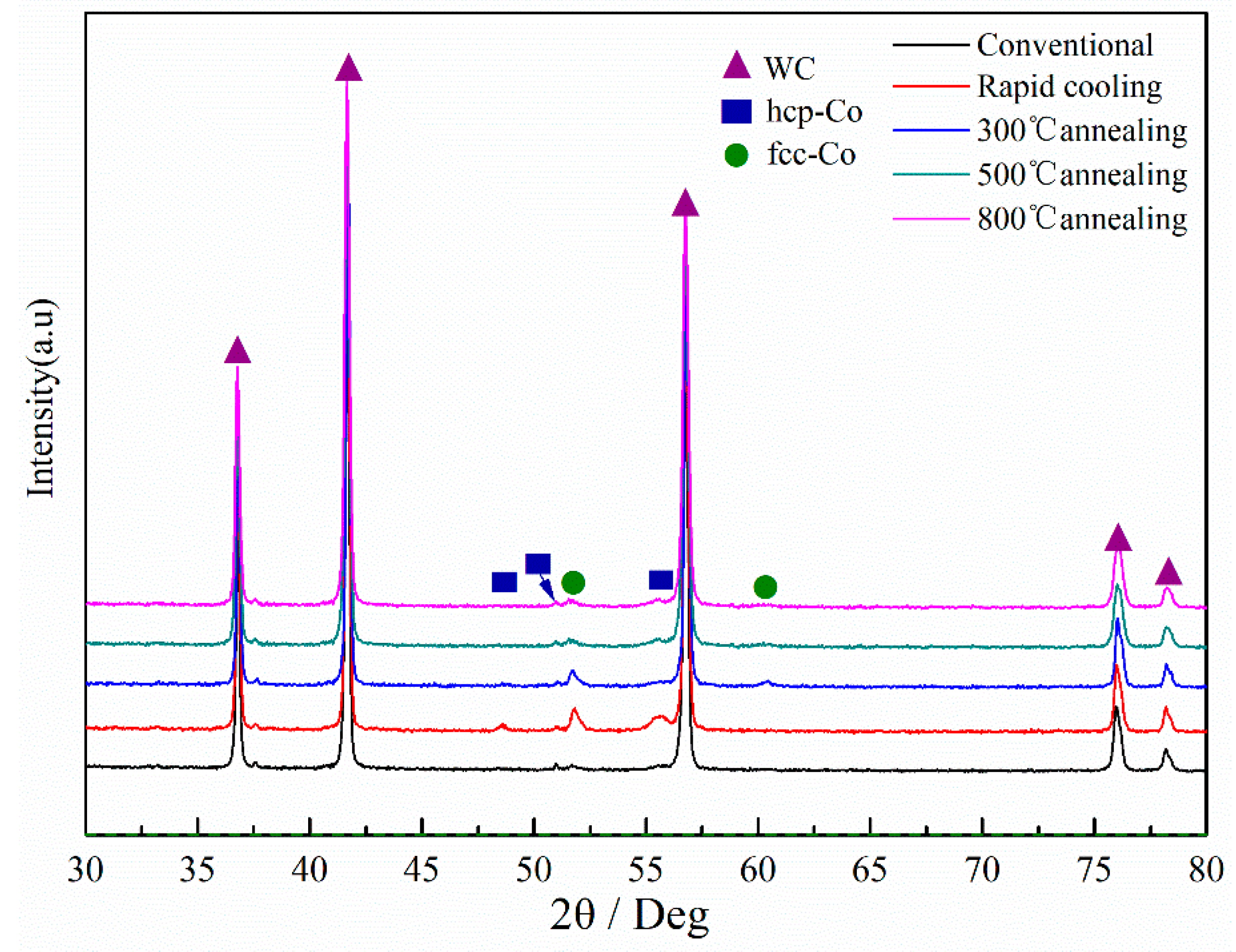
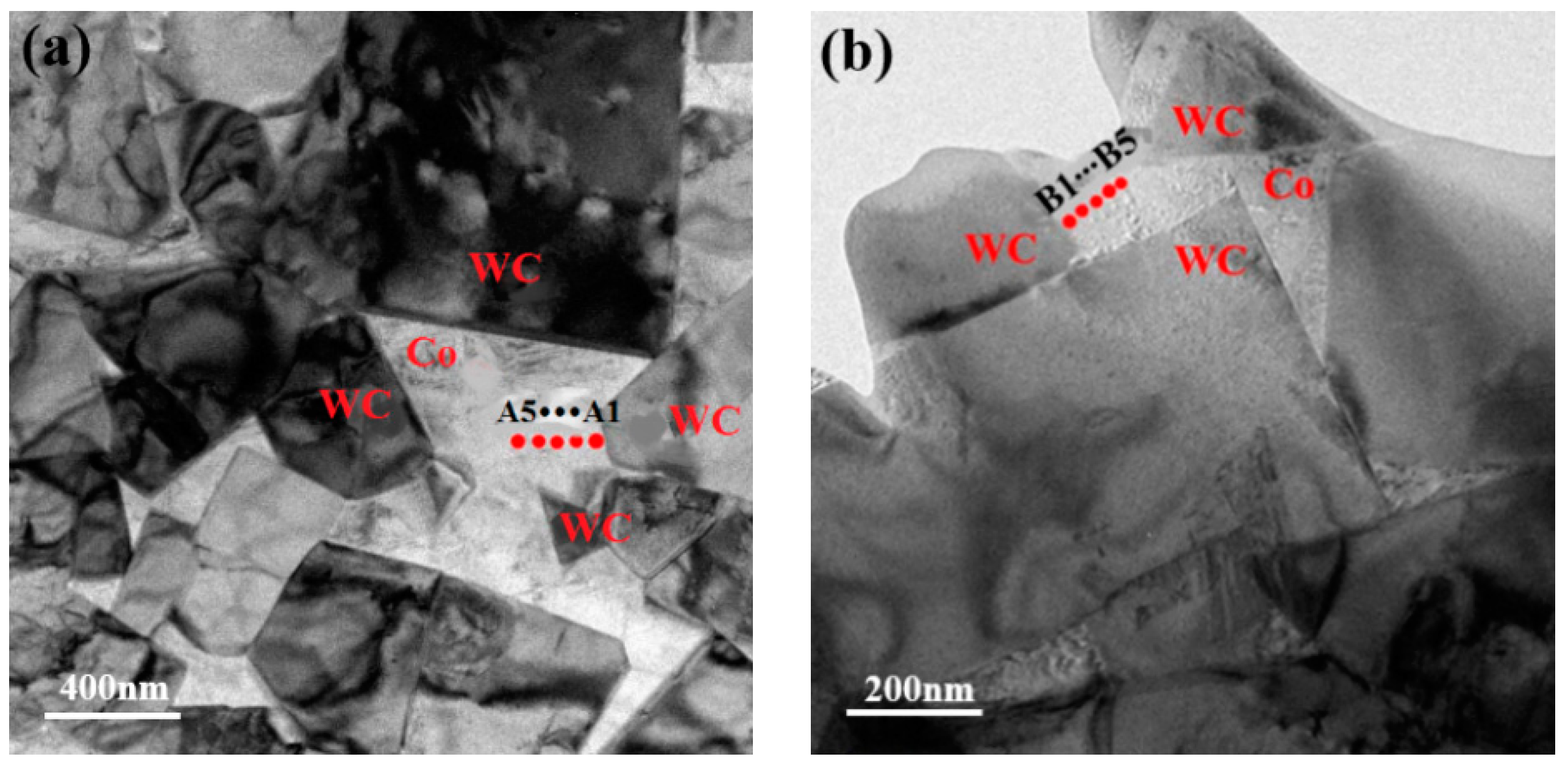
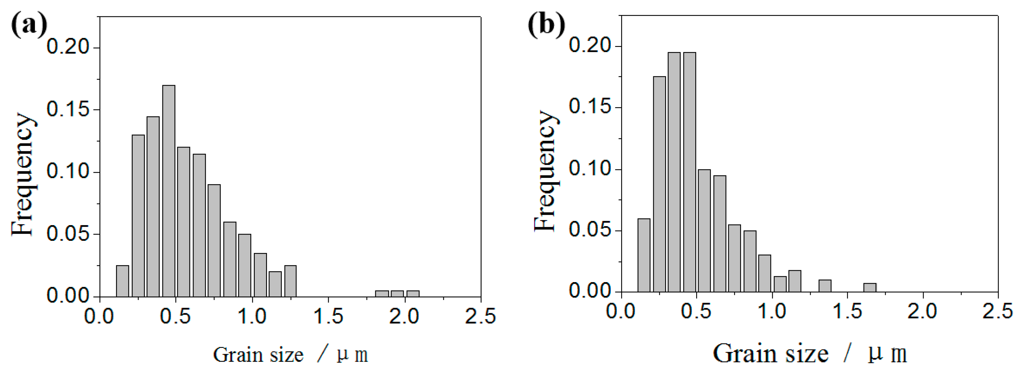
Microstructural differences in the ultrafine-grained WC–Co cemented carbides treated by conventional and rapid cooling processes were mainly reflected in the Co phase. With the rapid cooling treatment, the solid solubility of the W and the proportion of fcc Co in the Co phase increased. In terms of the effect on the hard phase (WC), the rapid cooling treatment inhibited the precipitation of the W and C atoms on the surface of WC particles which resulted in rounding of the WC grain edges and refinement of the WC grains.
(2)
The presence of nanosized particles increased the dispersion strengthening of the Co phase which improved the comprehensive properties of the ultrafine-grained WC–Co cemented carbide and increased the hardness, wear resistance, and toughness of the alloys.
(3)
The ultrafine-grained WC–Co cemented carbide with good hardness and toughness was obtained by strengthening the Co phase through an appropriate heat treatment process, and the service life of the ultrafine-grained WC–Co cemented carbide was improved under actual cutting conditions.

Author Contributions

Conceptualization, Z.X. and P.D.; methodology, Z.X.; validation, Z.L.; formal analysis, Z.X.; investigation, Z.L.; data curation, F.C.; writing—original draft preparation, Z.X.; writing—review and editing, Z.X.; visualization, Z.L.; supervision, P.D.; project administration, P.D.; funding acquisition, P.D.

Funding

This research was funded by Science and Technology Major Project of Fujian , grant number 2017HZ0001-1. The authors thank the funding for University-Industry cooperation project in Fujian Province under project 2019H6022.

Conflicts of Interest

The authors declare no conflict of interest.

References

  1. Tumanov, V.I.; Funke, V.F.; Trukhanova, Z.S.; Novikova, T.A.; Kuznetsova, K.F. The heat treatment of tungsten carbide-cobalt alloys. Trans. Poroshkovaya Metall. 1964, 2, 57–60. [Google Scholar] [CrossRef]
  2. Jonsson, H.; Aronsson, B. Microstructure and hardness of cobalt-rich Co-W-C alloys after ageing in the temperature range 400–1000 °C. J. Inst. Met. 1969, 97, 281–288. [Google Scholar]
  3. Jonsson, H. Studies of the binder phase in WC-Co cemented carbides heat-treated at 650 °C. Powder Metall. 1972, 15, 1–10. [Google Scholar] [CrossRef]
  4. Jonsson, H. Studies of the binder phase in WC-Co cemented carbides heat-treated at 950 °C. Planseeber. Pulvermetall. 1975, 1, 37–55. [Google Scholar]
  5. Wirmark, G.; Dunlop, G.L. Phase transformation in the binder phase of Co-W-C cemented carbides. In Science of Hard Materials; Springer: Boston, MA, USA, 1983; pp. 311–328. [Google Scholar]
  6. Parker, S.R.; Whiting, M.J.; Yeomans, J.A. Control of carbon content in WC-Co hard metal by heat treatment in reducing atmospheres containing methane. Int. J. Refract. Met. Hard Mater. 2017, 66, 204–210. [Google Scholar] [CrossRef] [Green Version]
  7. Sunny, Z.; Apurbba, K.S. Microstructure and wear performance of heat treated WC-12Co microwave clad. Vacuum 2016, 131, 213–222. [Google Scholar]
  8. Yuan, Y.G.; Ding, J.J.; Wang, Y.K.; Sun, W.Q. Fabrication of functionally gradient ultrafine grained WC-Co composites. Appl. Mech. Mater. 2013, 423–426, 885–889. [Google Scholar] [CrossRef]
  9. Fernandes, C.M.; Guisbiers, G.; Pereira, S.; Barradas, N.P.; Alves, E.; Senos, A.M.R.; Vieira, M.T. Annealing Ni nanocrystalline on WC-Co. J. Alloy. Compd. 2009, 482, 131–136. [Google Scholar] [CrossRef]
  10. Ho, W.Y.; Chen, C.W.; Wang, D.Y.; Ho, W.Y. Cutting performance of TiAlSiN coated cemented carbide tool with post-deposition heat treatment. Adv. Mater. Res. 2009, 79–82, 767–770. [Google Scholar] [CrossRef]
  11. Saito, Y.; Isozaki, T.; Masuda, A.; Fukumoto, K.; Chosa, M.; Ito, T.; Bauer, C.E.; Inspektor, A.; Oles, E.J. Adhesion strength of diamond film on cemented carbide insert. Diam. Relat. Mater. 1993, 2, 1391–1395. [Google Scholar] [CrossRef]
  12. Chae, K.W.; Park, J.K.; Lee, W.S. Adhesion strength of diamond films on heat-treated WC-Co cutting tools. Diam. Relat. Mater. 2007, 16, 1992–1995. [Google Scholar] [CrossRef]
  13. Delfosse, D.; Cherradi, N.; Ilschner, B. Numerical and experimental determination of residual stresses in graded materials. Compos. Part B Eng. 1997, 28, 127–141. [Google Scholar] [CrossRef]
  14. Thakur, D.; Ramamoorthy, B.; Vijayaraghavan, L. Influence of different post treatments on tungsten carbide cobalt inserts. Mater. Lett. 2008, 62, 4403–4406. [Google Scholar] [CrossRef]
  15. Routala, P.; Norton, J.T. Tungsten-Cobalt-Carbon System. Trans. AIME 1952, 4, 1045–1050. [Google Scholar] [CrossRef] [Green Version]
  16. Andrén, H.-O. Microstructures of cemented carbides. Mater. Des. 2001, 22, 491–498. [Google Scholar] [CrossRef]
  17. Fernandes, C.M.; Senos, A.M.R. Cemented carbide phase diagrams: A review. Int. J. Refract. Met. Hard Mater. 2011, 29, 405–418. [Google Scholar] [CrossRef]
  18. Gu, L.; Huang, J.; Tang, Y.; Xie, C.; Gao, S. Influence of different post treatments on microstructure and properties of WC-Co cemented carbides. J. Alloy. Compd. 2015, 620, 116–119. [Google Scholar] [CrossRef]
  19. Tan, Y.; Cai, H.; Liu, Z.; Zhu, W.; Ma, B. TEM Investigation of WC-Co Cemented Carbides after Heat Treatment. Rare Met. Mater. Eng. 1997, 26, 58–62. [Google Scholar]
  20. Andrén, H.-O. Microstructure development during sintering and heat-treatment of cemented carbides and cermets. Mater. Chem. Phys. 2001, 67, 209–213. [Google Scholar] [CrossRef]
  21. Cheng, X.; Zhang, L. Effects of heat treatment on the mechanical properties of coarse-grained cemented carbide. Rare Met. Cem. Carbides 2012, 40, 45–47. [Google Scholar]
  22. Wang, C.X.; Jiang, C.H.; Ji, V. Thermal stability of residual stresses and work hardening of shot peened tungsten cemented carbide. J. Mater. Process. Technol. 2017, 240, 98–103. [Google Scholar] [CrossRef]
  23. Fang, Z.Z. Correlation of transverse rupture strength of WC-Co with hardness. Int. J. Refract. Met. Hard Mater. 2005, 23, 119–127. [Google Scholar] [CrossRef]
  24. Cha, S.I.; Lee, K.H.; Ryu, H.J.; Hong, S.H. Effect of size and location of spherical pores on transverse rupture strength of WC-Co cemented carbides. Mater. Sci. Eng. A 2008, 486, 404–408. [Google Scholar] [CrossRef]
  25. Li, J.Y.; He, P. Study on microstructure and properties of WC-Co cemeneted carbide. Rare Met. Mater. Eng. 1995, 24, 53–58. [Google Scholar]
  26. Xiao, M.D.; Xiao, W.; Jiang, J.L. Cobalt phase structure of cemented carbide. Mater. Sci. Eng. Powder Metall. 2010, 15, 611–614. [Google Scholar]
  27. Konyashin, I.; Lachmann, F.; Ries, B.; Mazilkin, A.A.; Straumal, B.B.; Kübel, C.; Llanes, L.; Baretzky, B. Strengthening zones in the Co matrix of WC–Co cemented carbides. Scr. Mater. 2014, 83, 17–20. [Google Scholar] [CrossRef]
  28. Makhele-Lekala, L.; Luyckx, S.; Nabarro, F.R.N. Semi-empirical relationship between the hardness, grain size and mean free path of WC-Co. Int. J. Refract. Met. Hard Mater. 2001, 19, 245–249. [Google Scholar] [CrossRef]
  29. Tillwick, D.L.; Joffe, I. Precipitation and magnetic hardening in sintered WC-Co composite materials. J. Phys. D 1973, 6, 1585–1597. [Google Scholar] [CrossRef]
  30. Wawrzik, S.; Buchegger, C.; Lengauer, W.; van den Berg, H.; Rödiger, K.; Wolf, M.; Helldörfer, A.; Bernardi, J.; Gruber, J. Precipitation of intermetallic phases in coarse-grained hardmetals by low-temperature annealing. In Proceedings of the EuroPM 2015, Reims, France, 4–7 September 2015. [Google Scholar]
Figure 1. Schematic diagram of the heat treatment process.
Metals 09 01302 g001
Figure 2. XRD patterns of the different heat-treated alloys. The peak position of the cobalt phase is marked with a blue line.
Metals 09 01302 g002
Figure 3. TEM morphology of (a) conventional alloys and the (b) rapidly cooled alloys.
Metals 09 01302 g003
Figure 4. SEM morphology of (a) conventional alloys and the (b) rapidly cooled alloys.
Metals 09 01302 g004
Figure 5. Grain size distribution statistics of (a) conventional alloys and the (b) rapidly cooled alloys.
Metals 09 01302 g005
Figure 6. TEM analysis of conventional alloy. (a) Low-magnification morphology; (b) magnified morphology of the Co phase, and the SAED pattern of the Co phase in the red box region is shown in the lower right corner; (c) microstructure of the Co phase.
Metals 09 01302 g006
Figure 7. TEM analysis of the alloy that experienced rapid cooling from 1280 °C and was then annealed at 500 °C. (a) Low-magnification morphology; (b) phase interface of WC and Co, and the pattern of SAED of the Co phase in the red box region (inset in (b)), where the reflections from the nanoparticles are marked by yellow and those from the Co phase are marked by red; (c) microstructure of the Co phase and the fast fourier transformation (FFT) photos of the Co phase in the red region.
Metals 09 01302 g007
Figure 8. Schematic diagram of the standard four-edge end mills.
Metals 09 01302 g008
Figure 9. Flank wear of the end mills made with alloys treated by different heat treatment process.
Metals 09 01302 g009
Figure 10. Flank wear morphology of the end mills made with alloys treated by different heat treatment processes: (a) conventional alloys and (b) 1280 °C rapid cooling + 500 °C annealing alloy.
Metals 09 01302 g010
Table 1. Properties of alloy without and with heat treatment.
Heat Treatment ProcessMs%HcTRS (MPa)HV30KIC (MPa·m1/2)
Conventional alloy87 ± 2235 ± 124053 ± 651580 ± 3010.3 ± 0.3
1280 °C rapid cooling87 ± 2245 ± 124205 ± 581612 ± 2810.2 ± 0.2
1280 °C rapid cooling + 300 °C annealing88 ± 1240 ± 114293 ± 531610 ± 2610.5 ± 0.1
1280 °C rapid cooling + 500 °C annealing87 ± 1235 ±104253 ± 501602 ± 2510.8 ± 0.1
1280 °C rapid cooling + 800 °C annealing87 ± 3236 ±124181 ± 551593 ± 2710.3 ± 0.3
Table 2. XRD analysis of alloy without and with heat treatment.
Heat Treatment ProcessCo(hcp)(100)(°)Co(fcc)(200)(°)Co(hcp)/Co(fcc)
StandardActualStandardActual
Conventional alloy48.6848.4260.6360.070.23
1280 °C rapid cooling48.2459.970.16
1280 °C rapid cooling + 300 °C annealing48.3860.040.17
1280 °C rapid cooling + 500 °C annealing48.3860.050.36
1280 °C rapid cooling + 800 °C annealing48.4160.080.41
Table 3. EDS component analysis of Co phase region (wt.%).
SitesWCrCoSitesWCrCo
A16.153.0988.77B110.541.887.64
A29.271.8387.72B29.571.5788.85
A37.812.8489.34B38.981.6785.26
A47.962.6589.37B48.821.4484.61
A57.011.6191.36B59.771.688.64
Table 4. Cutting parameters for the cutting experiments.
Speed (rpm)fz (mm/rev)ap (mm)ae (mm)Cutting ModeCooling ModeWorkpiece Material
6110.0412.76.35groove milling7% water-based emulsionInconel 718

