Article

Study on Surface Longitudinal Crack Formation of Typical Hypoeutectoid Steel Produced on a Caster with Billet and Slab

1
State Key Laboratory of Advanced Metallurgy, University of Science and Technology Beijing, Beijing 100083, China
2
China Petroleum Materials Procurement Center, China National Petroleum Corporation, Beijing 100029, China
3
Xiangtan Iron & Steel Co., Ltd. of Hunan Valin, Xiangtan 411101, China
*
Author to whom correspondence should be addressed.
Metals 2019, 9(12), 1269; https://doi.org/10.3390/met9121269
Submission received: 15 November 2019 / Revised: 23 November 2019 / Accepted: 26 November 2019 / Published: 27 November 2019

Abstract

:
This paper investigates the formation mechanism of typical hypoeutectoid steel with longitudinal cracks produced on a caster with billet and slab. It was found that the microstructure of the proeutectoid ferrite is the most critical factor affecting the longitudinal crack. The formation conditions of the proeutectoid ferrite and the reasonable control direction were determined through experiments and calculations. High-temperature tensile experiments revealed that enhanced cooling did not cause additional cracks. Therefore, the final plan was to reduce the formation of proeutectoid ferrite by strengthening the cooling process. As a result, the optimized surface temperature quickly passed the phase transition region of the proeutectoid ferrite and no cracks were found in the optimized billet.

1. Introduction

In the industrial continuous casting (CC) process, the probability of surface cracking is high, which not only affects the quality of the product and the rhythm of production, but also increases the production cost of steel [1,2]. The presence of cracks seriously affects the material properties such as strength, hardness, ductility and toughness. Hence, control of cracks formation is currently a crucial issue, as industry engineering develops rapidly [3]. The causes of cracks in various steel grades are different, and there are corresponding control methods for different types of cracks [4,5,6,7,8,9,10,11,12,13]. Wang et al. [14] analyzed the effect of inclusions on the initiation of cracks. Zhang et al. [15] eliminated transverse corner cracks in low-carbon steel by optimizing the cooling strategy to avoid brittleness in certain parts of the steel. Ma et al. [3] investigated the effects of precipitates and pro-eutectoid ferrite on surface cracks in micro-alloyed steel. Brimacombe et al. [16] suggested that the impinging metal stream, steel composition, and end-plate taper significantly influence the formation of longitudinal midface cracks. Li et al. [17] analyzed the effect of subsurface microstructure evolution on the transverse crack of micro-alloyed steel. Kong et al. [11] predicted the formation of cracks by using mathematical model.
A longitudinal crack is a typical surface crack that often occurs in hypoeutectoid steel [16,18,19]. Researchers usually control the longitudinal crack by improving the properties of the mold power [20], stabilizing the heat flow of the mold [21], using a suitable taper and pouring temperature, etc [12,16,22,23,24,25]. However, as the problem of longitudinal cracking persists, longitudinal cracks caused by the precipitation phase have rarely been researched. This is the case with proeutectoid ferrite the grain boundary and its vicinity are inherently weaker than the interior of the grain. Proeutectoid ferrite, which is precipitated along the austenite grain boundary, reduces the continuity of austenite, and crack sensitivity increases as a result [3,15,17,26]. The factors that affect the formation of proeutectoid ferrite include chemical composition, cooling rate, heating temperature, and holding time [27]. Among those factors, the cooling rate is the most easily controlled in the production process currently used in steel plants [28].
This paper provids the a detailed analysis of a billet of hypoeutectoid steel with a longitudinal crack produced on a caster with billet and slab. First, we analyzed the microstructure of the crack on the sample. Second, an experimental test and the corresponding calculations were used to determine the formation conditions of proeutectoid ferrite. Third, a high-temperature thermal simulator (Gleeble 1500, Dynamic Systems Inc., Poestenkill, NY, USA) was utilized to analyze the thermoplasticity of the steel, in order to ensure that the enhanced cooling did not cause additional cracks. Fourth, we determined the best position from which to increase the water flow by calculating the surface temperature of the billet using numerical simulation. Finally, the macroscopic morphology and microstructure of the billet surface were observed, and the crack of the steel was completely controlled once the process was optimized.

2. Materials and Methods

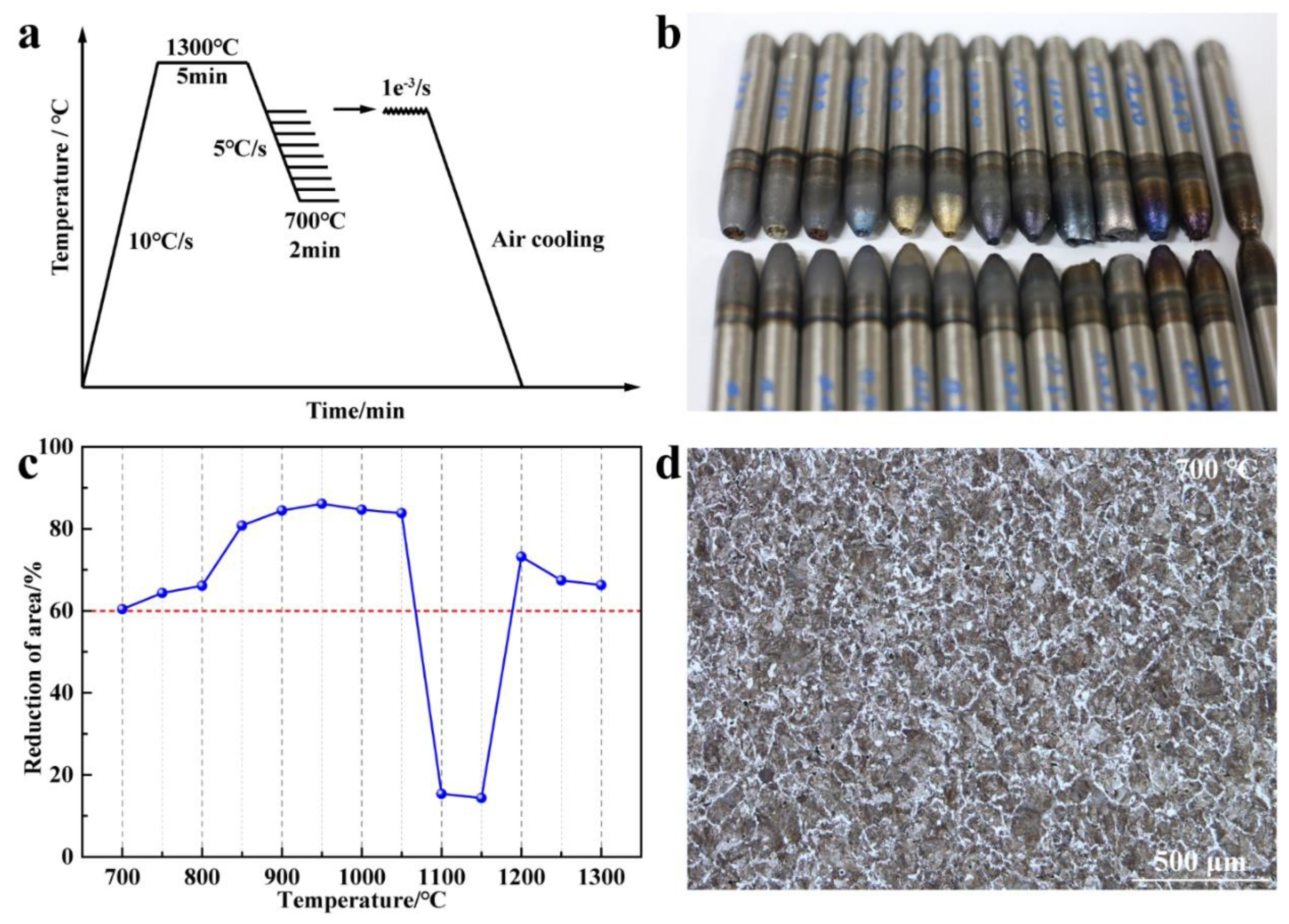
2.1. Materials and Experimental Procedure

The surface crack specimens were sampled from a billet produced by Xiangtan Iron & Steel Co., Ltd., of Hunan Valin, with a cross-section of 300 × 430 mm2. The chemical compositions of the steel samples are shown in Table 1. The surface rust was etched off with a solution of HCl/H2O at a 1:1 ratio for 30 min. Specimens of 10 × 10 × 10 mm3 were cut from the surface of the billet for subsequent analysis. The specimens were ground, polished, and then etched in a 4% nital solution for about 10 s. The microstructure of the specimens was then observed with an optical microscope (OM, DM4M, Leica, Wetzlar, Germany). The microhardness of the different microstructures was measured by a micro-hardness tester (THV-1MDX, Jiu bin, Shanghai, China). Tensile tests of steel as-cast samples were carried out at different temperatures by using a Gleeble 1500 thermal simulator at a strain rate of 10−3, s−1 to detect the hot ductility of the steel. The continuous cooling transformation (CCT) curves of the different steel samples were first calculated using JMatPro 7.0 software (Thermotech, Rossendale, UK) and then experimentally verified with a RITA Dilatometer (L78, Baehr-Thermo, Hüllhorst, Germany). The surface temperature of the billet was numerically simulated using ProCAST software and verified with an infrared thermometer (PT300-HW, Wu Jiu, Shanghai, China).

2.2. Numerical Model

In this paper, we applied the method of two-dimensional (2D) slicing to the billet, and the different boundary conditions in the continuous casting direction to simulate the steady heat transfer of a pseudo -three-dimensional (3D) model. Boundary conditions were handled as follows:
(1)
Heat transfer in the direction of continuous casting was ignored.
(2)
The heat flow rate in the mold can be expressed by
q m   =   2680000     301360 · Z V c .
(3)
The heat transfer coefficient in water spray cooling can be represented by
h w   =   1.57 · W 0.55 · 1     0.0075 · T w 4 .
(4)
The heat transfer coefficient in mist (water + air) cooling can be represented by
h s   =   391 · W   0.451 .
(5)
The heat flow rate in the radiation cooling zone can be expressed by
q r   =   σ · ε · ( T 0 4 T a 4 ) .

3. Results and Discussion

3.1. Longitudinal Crack Distribution and Features

Many small longitudinal cracks appear on the surface of a billet when producing 42CrMo1-08 blooms on a caster with billet and slab in a steel plant. However, it is difficult to find the defect before the acid etches off the surface rust. As shown in Figure 1a, there were 33 small longitudinal cracks on the wide face of the billet and 26 small longitudinal cracks on the narrow face. The length of the cracks was between 5 and 10 mm. The sample with the cracks was cut along the cross-section of the billet. Then, the sample was observed with an OM, after ground and polished. In the specimens with cracks on the wide face, the depth of the cracks (≈400 μm) is generally smaller than that of the specimens with cracks on the narrow face (≈1200 μm; Figure 1b). No obvious foreign matter was found inside the cracks, which indicates that they were not caused by inclusions.

3.2. Analysis of the Causes of Longitudinal Cracks

First, the microstructure near the cracks (Figure 2) was analyzed in order to determine why the cracks occured. The result shows that there was no decarburized layer near the crack, which indicates that the crackwas generated at a relatively low temperature (<850 °C) whilst many proeutectoid ferrites precipitated along the grain boundary on the surface of the billet. The largest size of the narrow-faced proeutectoid ferrite (188 vs. 354 μm) and the proportion of proeutectoid ferrite at a depth of 500 μm below the surface (20% vs. 55%) are larger than those of the wide-faced proeutectoid ferrite. Compared with the wide face, the proeutectoid ferrite on the narrow face appeared not only on the grain boundary but also in the crystal. This indicates that the cooling rate of the narrow face was lower than that of the wide face. More interestingly, the cracks were all caused by proeutectoid ferrite precipitated along the grain boundary.
Hypoeutectoid steel inevitably forms proeutectoid ferrite along the austenite grain boundary at temperatures below A3 (as shown in Figure 3a), which eventually forms a ferrite film [29]. Firstly, the strength of ferrite grains is much lower than that of austenite. In addition, the presence of a ferrite film interrupts the austenite’s continuity. Hence, the stress tends to accumulate on the ferrite film. Secondly, the grain boundary is weakened by factors such as precipitation along the grain boundary. The strength of the grain boundary is therefore lower than that inside the grain. Finally, the precipitation of the ferrite film precipitates along the grain boundary further weakens the boundary. When the strength is lower than the stress generated in the vicinity thereof, cracks appear in the ferrite film deposited along the grain boundary (Figure 3b).
In order to visually and quantitatively determine the difference in hardness between the pro-eutectoid ferrite and the matrix, a microhardness test was performed using a microhardness tester. Figure 4 shows that the average microhardness of proeutectoid ferrite was lower than that of the matrix with 37 Vickers-hardness (HV). It has been proven once again that proeutectoid ferrite is a limiting factor with respect to a sample’s material properties. Therefore, it is necessary to control proeutectoid ferrite in order to decrease cracks.

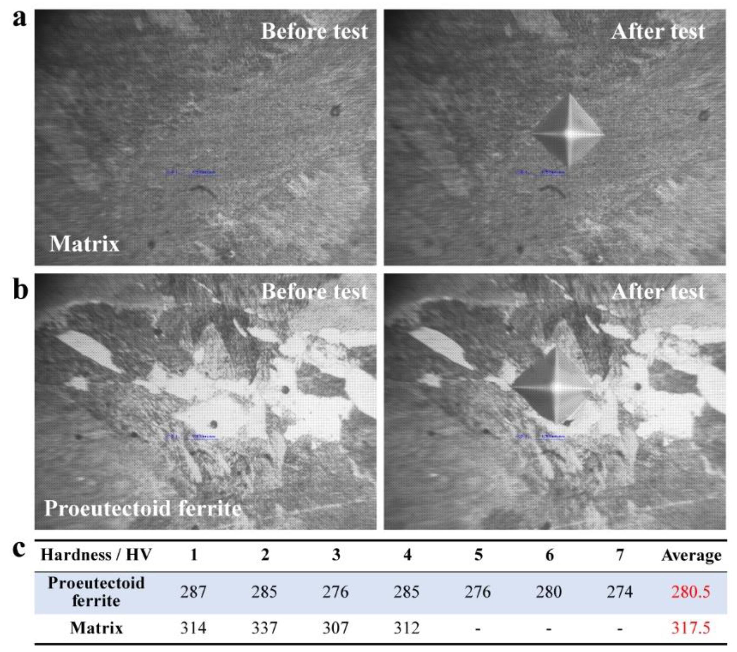
3.3. Determining the Conditions for the Formation of Proeutectoid Ferrite

As mentioned earlier, the cooling rate is the easiest way to control the formation of proeutectoid ferrite during continuous casting. JMatPro software was used to calculate the transformation behavior of a microstructure under different cooling rates. Figure 5 shows that ferrite and pearlite precipitate when the cooling rate is lower than about 40 and 5 °C/min, respectively. In other words, due to the temperature recovery on the surface of the billet, the surface cooling rate in the stage of transition from austenite to ferrite is slower than 40 °C/min.
To verify the accuracy of the calculation, the CCT curves were tested using a dilatometer. The temperature control program is shown in Figure 6a. The sample was firstly austenitized at 900 °C for 10 min to ensure that fine recrystallized austenite grains would be the first microstructure obtained before the transformation [30]. The CCT curves of the experimental test are represented in Figure 6b, which shows good agreement and consistency with the calculated results. Ferrite begins to precipitate when the temperature is below 700 °C and the cooling rate is below 50 °C/min. Therefore, in order to control the quantity and size of the proeutectoid ferrite, the cooling rate should be when the surface temperature of the billet reaches 900 °C, whilst the cooling rate should be kept as much as possible around 50 °C/min.
A hot tensile test was performed to measure the thermoplasticity of the steel. The temperature control program is shown in Figure 7a. Firstly, the sample was heated to 1300 °C at a heating rate of 10 °C/s and held for 5 min. Then it was cooled to the target temperature (700–1300 °C) at a cooling rate of 5 °C/s and held for 2 min. Afterwards, it was stretched until it broke, and finally air cooled to room temperature. The photo of the tensile specimen after pulling off is shown in Figure 7b. The hot ductility curve obtained is shown in Figure 7c. When the hot tensile test was carried out at 1100 and 1150 °C, the reduction of area (RA) reached the lowest value (≈15%), attesting to the hot brittleness of 42CrMo1-08 at high temperatures. No decarburization layer was found near the crack, which indicates that the crack was not caused by high-temperature (1100–1150 °C) hot brittleness under the original process conditions. Hence, the cooling condition at high temperature should be maintained. When the hot tensile test was carried out between 1050 and 700 °C, the RA decreased along with the temperature. However, the RA in the temperature range of 700-1050 °C was greater than 60%, which indicates that the thermoplasticity of the steel was outstanding. Therefore, the reinforced cooling of the surface temperature of the billet at 900 °C will not cause cracks due to the steel’s excellent plasticity. The microstructure near the fracture of the hot tensile specimen at 700 °C is shown in Figure 7d. When a hot tensile test at 700 °C was carried out, a large amount of pro-eutectoid ferrite was found in the grain boundary. As a result, it should pass 700 °C quickly to reduce crack sensitivity in actual production.

3.4. Optimization of Local Secondary Cooling

In general, the resulting microstructure near the crack shows that the crack is generated at a low temperature and is closely related to the pro-eutectoid ferrite. Because steel has a brittle zone at high temperatures (1100–1150 °C), the reinforced cooling experiment was carried out only in a low-temperature zone, at 900 °C, whilst the cooling strength in the high-temperature zone was left unchanged. However, the location of the low-temperature zone was difficult to determine. Thus, numerical simulation was used to determine the location of the billet temperature below 900 °C. The caster with billet and slab is shown in Figure 8. When the caster with billet and slab produces a billet, the spray zone is similar to that of a normal slab caster. Therefore, the overall cooling is uneven and weak, which leads the number and width of the narrow-faced proeutectoid ferrite to surpass those of the wide-faced proeutectoid ferrite. The spray zone location and the water flow rate distribution in the secondary cooling zones of the caster are shown in Table 2. It is worth noting that the water flow is intermittent from zone 6 on, and that the cooling water of the inner arcs in zones 9 and 10 is used to cool the rollers. The outer arc, on the other hand, is air-cooled, which inevitably leads to insufficient cooling. The narrow face in zone 5-10 has no cooling water. Accordingly, the cooling rate of the narrow face is lower than that of the wide face, which results in the amount of the narrow-faced pro-eutectoid ferrite being larger than that of the wide-faced one.
The temperature field of the billet was calculated by establishing a numerical model. The required parameters are shown in Table 2 and Table 3. The temperature profile at different positions of the billet, under the original cooling conditions, is shown in Figure 9. The temperature of the narrow face gradually increased from the mold region to the spray cooling zone 5, whilst the temperature of the narrow surface gradually decreased in the subsequent spray cooling zone. The inner and outer arcs of the wide face repeatedly passed the A3 point in zone 7, and the temperature slowly decrease during this process. The surface temperature of the slab was measured by an infrared thermometer, and the calculated results show a good fit with the experimental results. The wide/narrow-face temperature reached 900 °C at a position of about 25 m from the meniscus, which means that the pro-eutectoid ferrite requires a long incubation time. In order to weaken the kinetic conditions of pro-eutectoid ferrite formation, we decided to increase the flow rate of water from zone 7 to minimize the growth of pro-eutectoid ferrite. The suggested water flow rate is also shown in Table 2. The temperature profile of the billet after the optimization of the water flow rate is shown in Figure 9. The surface temperature of the billet quickly reached 900 °C and the surface temperature rose much less than before. The surface temperature after the optimization of the inner arc was tested using a hand-held infrared thermometer. The errors between the test result and the calculation result were less than 3%, which confirmed the credibility of the model result.
The optimized secondary cooling scheme was validated in industrial practice. The optimized billet was sampled, acid etched to remove the surface rust, and photographed as shown in Figure 10a,b. No longitudinal cracks were found on either the broad or narrow side of the billet, which strongly suggests that the optimization scheme is well worth promoting. Further analysis of the surface sample (Figure 10c–f) shows that both the number and the width of the pro-eutectoid ferrite in the wide and narrow faces are effectively controlled. The proportion of pro-eutectoid ferrite at a depth of 500 μm below the surface is only about 3%. It is worth noting that the narrow-faced intragranular ferrite completely disappeared after the optimization process.

4. Conclusions

This paper offers a detailed analysis of the causes of longitudinal cracks in hypoeutectoid steel produced on a caster with billet and slab. Moreover, it indicates the direction of crack control. The research conclusions can be summarized as follows:
(1) The formation of pro-eutectoid ferrite is the main cause of longitudinal cracks in hypoeutectoid steel. Due to uneven and insufficient cooling of the narrow face of the caster with billet and slab, the narrow surface is more likely to crack, and the cracks are deeper than those on the wide surface.
(2) The microhardness of pro-eutectoid ferrite is 37 HV lower than that of the matrix. Hence, the stress tends to accumulate on the ferrite film, and the cracks occur when it reaches the ultimate stress of the steel.
(3) It was found that the precipitation of pro-eutectoid ferrite can be effectively controlled when the cooling rate is as close to 50 °C/min as possible. Furthermore, the reinforced cooling of the billet will not cause cracks, due to the excellent plasticity of the steel.
(4) After determining the surface temperature of the billet through the numerical simulation, we decided to strengthen the cooling after zone 6. As a result, the surface temperature quickly passed through the phase transition zone of the pro-eutectoid ferrite, and the longitudinal cracks on the surface no longer occurred.

Author Contributions

Conceptualization, L.X. and Y.B.; methodology, F.Z. and B.C.; software, Z.Z.; formal analysis, M.W.; investigation, L.X.; writing—original draft preparation, L.X.; writing—review and editing, L.X. and J.G.

Funding

This work was financially supported by the National Natural Science Foundation of China (No. 51774031).

Conflicts of Interest

The authors declare no conflict of interest.

References

  1. Xie, H.; Jiang, Z.; Yuen, W.Y.D. Analysis of Microstructure Effects on Edge Crack of Thin Strip During Cold Rolling. Metall. Mater. Trans. B 2011, 42, 1244–1252. [Google Scholar] [CrossRef]
  2. Brimacombe, J.K.; Sorimachi, K. Crack formation in the continuous casting of steel. Metall. Trans. B 1977, 8, 489–505. [Google Scholar] [CrossRef]
  3. Ma, F.J.; Wen, G.H.; Tang, P.; Yu, X.; Li, J.Y.; Xu, G.D.; Mei, F. Causes of transverse corner cracks in microalloyed steel in vertical bending continuous slab casters. Ironmak. Steelmak. 2013, 37, 73–79. [Google Scholar] [CrossRef]
  4. Saleem, S.; Vynnycky, M.; Fredriksson, H. The Influence of Peritectic Reaction/Transformation on Crack Susceptibility in the Continuous Casting of Steels. Metall. Mater. Trans. B 2017, 48, 1625–1635. [Google Scholar] [CrossRef]
  5. Tsuprun, A.Y.; Fedosov, A.V.; Pashchuk, D.V.; Tskitishvili, E.O.; Ottsevich, V.V. Reduction in Slab Surface Corner Crack Damage due to Development of Rational Secondary Cooling Regimes. Metallurgist 2014, 57, 824–829. [Google Scholar] [CrossRef]
  6. Ozturk, S.; Arikan, M.M.; Kacar, Y. Effects of Nickel Coating of Mold Plates on Star Crack Defects. Metall. Mater. Trans. B 2013, 44, 706–710. [Google Scholar] [CrossRef]
  7. Hui, Z.; Minglin, W.; Yeming, W.; Mei, W.; Xilin, L. Novel Casting Technology Preventing Slab Transverse Corner Cracks of Typical Micro-alloyed Steels. In Adv. High Strength Steel; Springer: Singapore, 2018; pp. 159–170. [Google Scholar]
  8. Zhang, H.; Yang, C.Z.; Wang, M.L.; Tao, H.B.; Liu, H.P.; Wang, X.B. Technology Development for Controlling Slab Transverse Corner Crack of Typical Micro-alloyed Steels. J. Iron Steel Res. Int. 2015, 22, 99–105. [Google Scholar] [CrossRef]
  9. Takeuchi, E.; Brimacombe, J.K. Effect of oscillation-mark formation on the surface quality of continuously cast steel slabs. Metall. Trans. B 1985, 16, 605–625. [Google Scholar] [CrossRef]
  10. Sinel’nikov, V.A.; Filippov, G.A. Production of high-quality slabs during continuous casting of cracking-sensitive steel: Part 2. Russ. Metall. 2015, 2014, 956–960. [Google Scholar] [CrossRef]
  11. Kong, Y.; Chen, D.; Liu, Q.; Long, M.A. Prediction Model for Internal Cracks during Slab Continuous Casting. Metals 2019, 9, 587. [Google Scholar] [CrossRef]
  12. Guo, J.; Wen, G. Influence of Alloy Elements on Cracking in the Steel Ingot during Its Solidification. Metals 2019, 9, 836. [Google Scholar] [CrossRef]
  13. Gu, C.; Bao, Y.P.; Gan, P.; Wang, M.; He, J.S. Effect of main inclusions on crack initiation in bearing steel in the very high cycle fatigue regime. Int. J. Miner. Metall. Mater. 2018, 25, 623–629. [Google Scholar] [CrossRef]
  14. Wang, Q.Y.; Bathias, C.; Kawagoishi, N.; Chen, Q. Effect of inclusion on subsurface crack initiation and gigacycle fatigue strength. Int. J. Fatigue 2002, 24, 1269–1274. [Google Scholar] [CrossRef]
  15. Zhang, L.; Yang, X.; Li, S.; Li, M.; Ma, W. Control of Transverse Corner Cracks on Low-Carbon Steel Slabs. JOM 2014, 66, 1711–1720. [Google Scholar] [CrossRef]
  16. Brimacombe, J.K.; Weinberg, F.; Hawbolt, E.B. Formation of longitudinal, midface cracks in continuously-cast slabs. Metall. Trans. B 1979, 10, 279–292. [Google Scholar] [CrossRef]
  17. Li, Y.F.; Wen, G.H.; Tang, P.; Li, J.Q.; Xiang, C.L. Effect of Slab Subsurface Microstructure Evolution on Transverse Cracking of Microalloyed Steel during Continuous Casting. J. Iron Steel Res. 2014, 21, 737–744. [Google Scholar] [CrossRef]
  18. Tehovnik, F.; Vodopivec, F.; Celin, R.; Arzenšek, B.; Gontarev, J. Effect of δ-ferrite, lead and sulphur on hot workability of austenitic stainless steels with solidification structure. Mater. Sci. Technol. 2013, 27, 774–782. [Google Scholar] [CrossRef]
  19. Mintz, B. The Influence of Composition on the Hot Ductility of Steels and to the Problem of Transverse Cracking. ISIJ Int. 1999, 39, 833–855. [Google Scholar] [CrossRef]
  20. Zhang, Y.; Wang, W.; Zhang, H. Development of a Mold Cracking Simulator: The Study of Breakout and Crack Formation in Continuous Casting Mold. Metall. Mater. Trans. B 2016, 47, 2244–2252. [Google Scholar] [CrossRef]
  21. Lyu, P.; Wang, W.; Zhang, H. Mold Simulator Study on the Initial Solidification of Molten Steel Near the Corner of Continuous Casting Mold. Metall. Mater. Trans. B 2016, 48, 247–259. [Google Scholar] [CrossRef]
  22. Sun, Y.H.; Ni, Y.J.; Wang, H.T.; Xu, Z.B.; Cai, K.K. Longitudinal surface cracks of thin slabs. Int. J. Miner. Metall. Mater. 2010, 17, 159–166. [Google Scholar] [CrossRef]
  23. Terčelj, M.; Turk, R.; Kugler, G.; Peruš, I. Neural network analysis of the influence of chemical composition on surface cracking during hot rolling of AISI D2 tool steel. Comput. Mater. Sci. 2008, 42, 625–637. [Google Scholar] [CrossRef]
  24. Shabovta, V.P.; Torgovets, A.K.; Maksimov, E.V. Formation of longitudinal cracks on slabs. Steel Transl. 2010, 40, 558–561. [Google Scholar] [CrossRef]
  25. Yang, G.; Zhu, L.; Chen, W.; Yu, X.; He, B. Initiation of Surface Cracks on Beam Blank in the Mold during Continuous Casting. Metals 2018, 8, 712. [Google Scholar] [CrossRef]
  26. Xu, L.J.; Zhang, S.L.; Qiu, C.G.; Qiu, S.T.; Zhang, X.Z. Surface microstructure control of microalloyed steel during slab casting. J. Iron Steel Res. Int. 2017, 24, 803–810. [Google Scholar] [CrossRef]
  27. Liu, Z.Q.; Yang, Z.G.; Li, Z.D.; Zhang, C. Transformation character of ferrite formation by a ledge mechanism under a mixed-control model. Int. J. Miner. Metall. Mater. 2012, 19, 428–433. [Google Scholar] [CrossRef]
  28. Ma, F.; Wen, G.; Wang, W. Effect of Cooling Rates on the Second-Phase Precipitation and Proeutectoid Phase Transformation of a Nb-Ti Microalloyed Steel Slab. Steel Res. Int. 2013, 84, 370–376. [Google Scholar] [CrossRef]
  29. Enomoto, M.; Yang, J.B. Simulation of Nucleation of Proeutectoid Ferrite at Austenite Grain Boundaries during Continuous Cooling. Metall. Mater. Trans. A 2008, 39, 994–1002. [Google Scholar] [CrossRef]
  30. Yamashita, T.; Enomoto, M.; Tanaka, Y.; Matsuda, H.; Nagoshi, M. Analysis of Carbon Partitioning at an Early Stage of Proeutectoid Ferrite Transformation in a Low Carbon Mn–Si Steel by High Accuracy FE-EPMA. ISIJ Int. 2018, 58, 1079–1085. [Google Scholar] [CrossRef] [Green Version]
Figure 1. (a) Scheme depicting the small longitudinal cracks on the billet. (b) Micromorphology of the cracked specimens.
Metals 09 01269 g001
Figure 2. Microstructure near cracks on specimens with a wide face (ac) and a narrow face(df).
Metals 09 01269 g002
Figure 3. (a) Partial magnification of the Fe-C phase diagram. (b) Scheme depicting the crack formation mechanism.
Metals 09 01269 g003
Figure 4. Microhardness test of (a) matrix and (b) proeutectoid ferrite. (c) Corresponding hardness values of matrix and proeutectoid ferrite.
Metals 09 01269 g004
Figure 5. Calculated continuous cooling transformation (CCT) curves of 42CrMo1-08 steel.
Metals 09 01269 g005
Figure 6. (a) The temperature control program used in CCT tests. (b) CCT curves of experimentally tested 42CrMo1-08 steel.
Metals 09 01269 g006
Figure 7. (a) The temperature control program used in hot tensile tests. (b) Photo of the broken sample. (c) Hot ductility curve of the steel. (d) The microstructure of the hot ductility test samples at 700 °C.
Metals 09 01269 g007
Figure 8. Schematic diagram of the caster with billet and slab.
Metals 09 01269 g008
Figure 9. Simulation of the surface temperature profile of the billet.
Metals 09 01269 g009
Figure 10. (a,b) Photo of the billet after optimization. The optimized microstructure of the billet’s wide face (c)and narrow face (d).
Metals 09 01269 g010
Table 1. Chemical composition of the steel samples (wt %).
SteelCSiMnPSCrMoAl
42CrMo1-080.390.210.750.020.0241.120.180.016
Table 2. Spray zone location and water flow rate distribution in the secondary cooling zones of the caster.
Spray ZoneLength (m)Water Flow Rate (L/min)Suggested Water Flow Rate (L/min)
1N0.7128128
1IO0.248787
2IO0.567575
3N1.113535
3IO1.114242
4N1.553535
4IO1.554040
5IO1.923636
6I3.841616
6O3.842121
7I3.84831
7O3.84831
8I6.63830
8O6.63946
9I6.871835
10I6.861835
Table 3. The parameters used in the model.
ParametersValueUnit
Billet cross section300 × 430mm2
Pouring temperature1522°C
Liquidus temperature1504°C
Solidus temperature1421°C
Mold length (Z)0.8m
Casting speed (Vc)0.65m/min
Latent heat of solidification272KJ/Kg
Density7400Kg/m3

