Article

An Experimental Study on the Erosion-Corrosion Performance of AISI 1018 Carbon Steel and AISI 304L Stainless Steel 90-Degree Elbow Pipe

Mechanical Engineering Department, Universiti Teknologi PETRONAS, Perak 32610, Malaysia
*
Authors to whom correspondence should be addressed.
Metals 2019, 9(12), 1260; https://doi.org/10.3390/met9121260
Submission received: 21 October 2019 / Revised: 8 November 2019 / Accepted: 12 November 2019 / Published: 25 November 2019

Abstract

:
Erosion-corrosion is an unavoidable material degradation process in flow pipelines transporting abrasive particles with carrier fluids. In this study, the multiphase flow loop apparatus is employed to assess the erosion-corrosion behavior and mechanism relative to AISI 1018 carbon steel (CS) and AISI 304L stainless steel (SS) 90° long radius elbows with the inner diameter of 50.8 mm. Fine silica sand of 50 µm average size was used as a dispersed phase and erosion-corrosion tests were conducted for slug flow conditions. The erosion-corrosion analysis of 90° elbows was determined from its surface morphologies before and after the experiment using confocal and scanning electron microscopy (SEM). The direct mass loss was measured to quantify the erosion-corrosion rate of the elbow configurations. Additionally, multilayer paint modeling experiments were performed to relate qualitative inferences on erosion distribution and location with the erosion-corrosion mechanism. It was observed that the erosion or corrosion pitting mechanism prevailed on the 1018 CS elbow surface, and the 304L SS displayed excellent erosion-corrosion resistance properties. Moreover, the erosion-corrosion rate was found to be 4.12 times more in the 1018 CS compared to the 304L SS with the maximum particle impaction identified at the exit of the horizontal-horizontal (H-H) 90° elbow for slug flow.

1. Introduction

Degradation of flow changing devices due to erosion-corrosion is a serious concern in hydrocarbon and mineral processing industries, especially those involved with solid particle transportation at high conveying velocities. In comparison to erosion induced damage, the action of cumulative degradation due to erosion and corrosion can enhance the material removal rate of flow devices up to two times [1,2].
Erosion-corrosion resistance of ductile materials is governed by impact conditions, material properties, erodent characteristics, and flow conditions [3,4,5,6,7,8]. Many studies [1,9,10,11,12,13,14,15] are reported in the literature which highlight the erosion-corrosion phenomena of different types of carbon steel (CS) and austenitic stainless steel (SS). Both 304L SS and 1018 CS have excellent mechanical properties and high thermal persistence, which determine their ubiquitous applications in hydrocarbon and mineral processing pipeline systems. It is vital to evaluate the erosion-corrosion mechanism of both materials in order to mitigate induced damage due to erosion-corrosion in practice.
A 90° elbow is a critical component used to redirect flow in a pipeline network of hydrocarbon and mineral processing industries [1,16,17,18,19]. However, the long radius curvature geometry of 90° elbow results in severe particle impaction, rebound, and mass transfer at different locations around the elbow configurations [16,17]. The erosion wear and the cumulative erosion-corrosion mechanism of the 90° elbows have been experimentally evaluated by some authors to acquire meaningful data on the erosion-corrosion in elbow configurations for field working conditions [4,9,20]. In most studies, the mass loss of the whole elbow geometry is measured after the experiment to quantify the erosion-corrosion rate. This method allows quantifying the overall degradation rate on the elbow geometry, but it does not provide the location of degradation and distribution around the elbow. Because existing methods for mass loss measurements of elbows are inadequate, it is considered a necessity for the development of a technique to acquire useful experimental data for quantifying elbow erosion-corrosion rates under working conditions.
In a hydrocarbon production pipeline, the gas–liquid–solid flow patterns (i.e., stratified flow, bubbly flow, annular flow, and slug flow, etc.) are often observed at different transportation velocities [21,22]. Amongst these flow patterns, liquid–solid–gas slug flow is very commonly encountered under turbulent conditions. However, it is complicated due to the passage of multiple carrier phases and a dispersed phase with a highly turbulent slug front which enhances erosion-corrosion damage in flow changing devices [23,24].
Zeng et al. [10] observed that the degradation rate at the 90° elbow outer curvature was more than that at the inner curvature in liquid–sand flow conditions and increased as the flow approached downstream. Owen et al. [25] recently developed 90° elbow geometry to investigate erosion-corrosion damage of carbon steel and found that high material degradation inferred in erosion-corrosion conditions. Kesana et al. [26] investigated the effect of erodent size and carrier fluid viscosity on wear rate for multiphase flow conditions in 90° elbow geometry. Vieira et al. [27] carried out multiple experimental runs to evaluate 90° elbow erosion in multiphase flow. They concluded that elbow orientation strongly influences impact conditions and erosion rates. Parsi et al. [28] performed a numerical study to simulate pseudo-slug flow erosion in 90° elbow for sand particles. Results showed that the top of the elbow experiences maximum erosion for horizontal orientation.
Huang et al. [29] investigated the flow accelerated corrosion mechanism of carbon steel elbows using a flow loop apparatus and found the degradation rate increased when flow approached from the upstream to downstream. They also found that minimal corrosion manifested at the inner curvature. Liu et al. [30] experimentally investigated erosion-corrosion of pipelines to obtain valuable erosion-corrosion information in working conditions. They concluded hydrodynamic conditions inside the pipe would strongly affect erosion and localized corrosion. In liquid–solid–gas flow conditions, increasing the flow rate of carrier phases could restrain the corrosion and wash away the mineral deposits inside pipes. However, the local turbulences incurred at high transportation velocities could erode the protective layer on the metal surface and enhance erosion-induced damage [31,32,33].
So far, the flow-induced degradation of 90° elbow caused by erosive slug flow has not been thoroughly studied. Notably, little has been found on the performance of erosion-corrosion of the AISI 1018 carbon steel and AISI 304L stainless steel elbow configurations for slug flow. Understanding the erosion-corrosion mechanism of 1018 CS and 304L SS flow changing devices may be of vital importance to the hydrocarbon and mineral processing industries. This will also aid in the development of new erosion models for future tribological analysis.
In this study, the cumulative degradation mechanism of AISI 1018 CS and AISI 304L SS long radius 90° elbows in erosion-corrosion environment for erosive slug flow is discussed and compared. The experimental work was implemented in a closed flow loop apparatus to simulate the degradation by erosion-corrosion and fine silica sand in water–air slug flow. The degradation mechanism of the 90° elbow is explained through multilayer paint modeling, surface roughness analysis, mass loss analysis, microscopic analysis, hardness measurements, and SEM/EDX observation to evaluate the overall behaviors of 304L SS and 1018 CS materials in the multiphase flow conditions.

2. Experimental Methods and Materials

The 90° long radius elbows used for the erosion-corrosion experiment were cut into the bottom half (BH) and the upper half (UH) section before the test, as illustrated in Figure 1. The elbows specimen preparation involved axial cutting, grinding and polishing. The specimens were cut axially using the wire electrical discharge machining (WEDM) process, and surface finishes of 90° elbow internal surface were achieved through grinding and polishing procedures by reducing the internal surface to the low level of roughness. During the grinding and polishing process, the variable speed pneumatic angle grinding machine with a flap wheel grinding tool and sandpapers of different grit sizes were used and then polished with sponge disks using crystalline diamond suspension to achieve the adequate surface finish on the contact area before the test. Specimens were then cleaned with ethanol, dried with a heat gun, and placed in desiccators to avoid moisture exposure before the tests. Mass loss of each elbow section after a 10 h flow time was reported using a precision electronic balance (Mettler Toledo, OH, United States). Fine silica particles with a sub-angular shape were used as the erosive phase. The abrasive sand particle used in this study had a mean diameter of 50 ± 2 µm measured using a laser scattering particle size distribution analyzer (Malvern Mastersizer 2000, Worcestershire, UK). The microstructure of the abrasive particles and test materials are presented in Figure 2a–c. Table 1 shows the elemental composition of AISI 1018 carbon steel and AISI 304L stainless steel material which was measured by an optical emission spectrometry method and the hardness level of the material before and after the test was evaluated by using a Vickers hardness (Hv) tester (Leco LM 247AT, Saint Joseph, MO, USA). The Vickers hardness of the exit section was measured at an applied load of 5 N with an indentation time of 15 s utilizing a diamond indenter. The average value was reported for five measurements. 3D surface scans were performed using a laser scanning microscope (Sensofar, Barcelona, Spain) to evaluate surface topographies and roughness parameters of the different elbow’s sections, and waviness components were filtered out using a Gaussian filter. For surface characterization, square specimens of size 10 mm were cut from the inlet, middle, and outlet of the 90° elbows by a WEDM process to evade changes in the surface properties during specimen preparation. The 2D roughness profile value of the worn surface was measured for each square specimen over a sampling length of 3508.8 μm using a Sensofar S lynx microscope (Sensofar, Barcelona, Spain) to evaluate the surface roughening behavior of internal surface after erosion-corrosion.

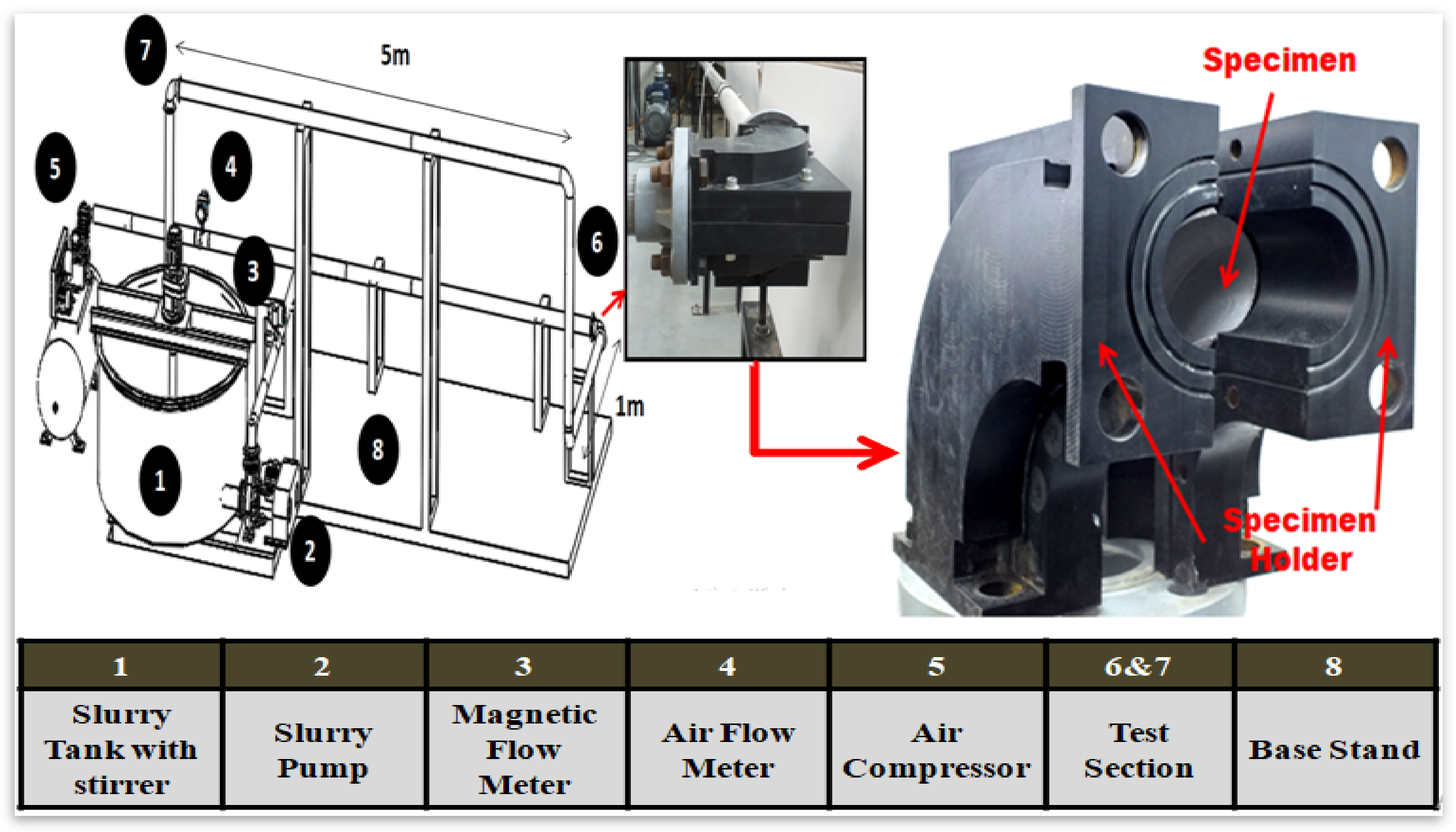
2.1. Multiphase Flow Loop Apparatus and Medium
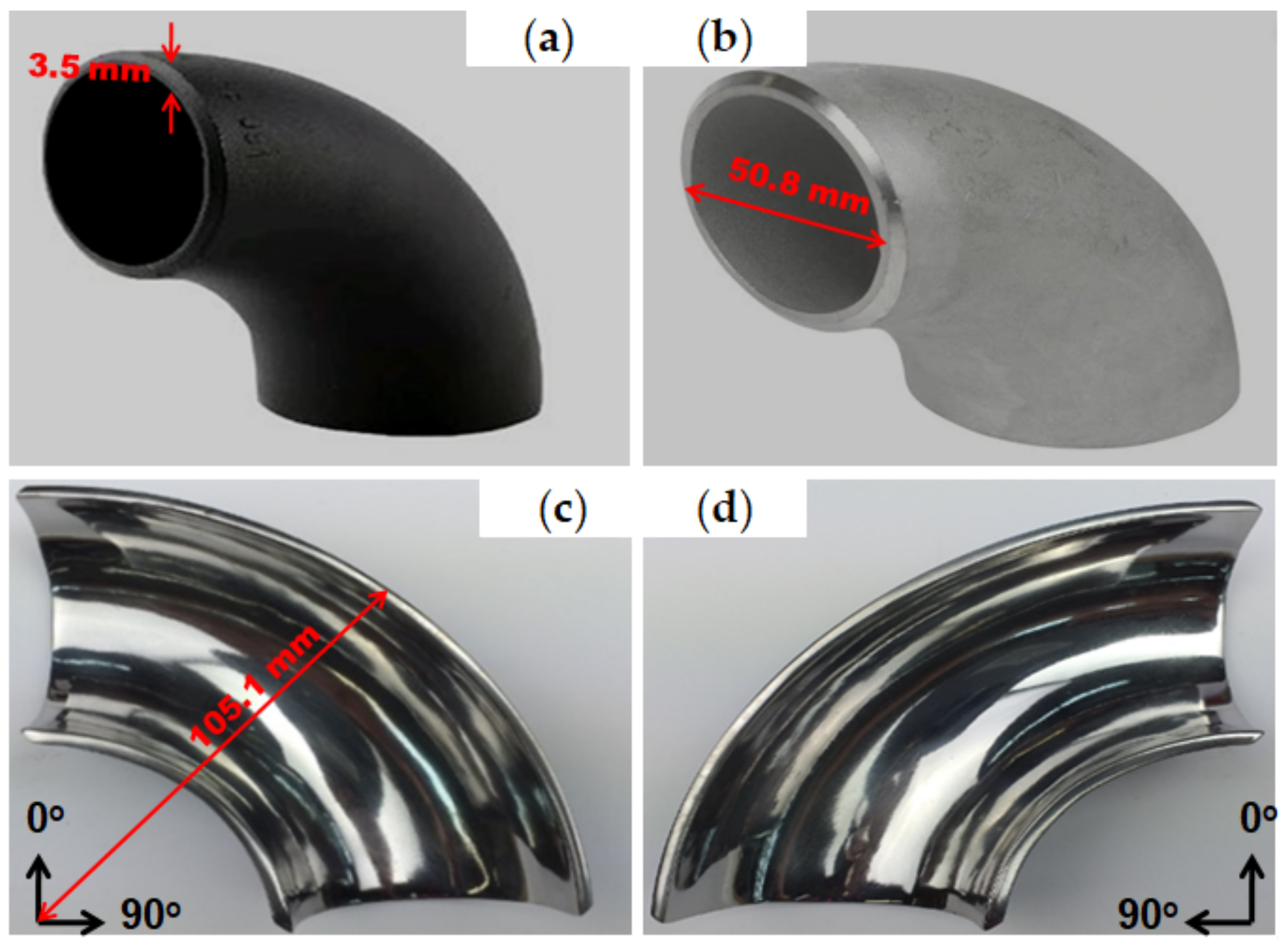
Figure 3 illustrates a schematic representation of the experimental apparatus employed to evaluate the erosion-corrosion performance of 90° elbow configurations. For the experiments presented in this work, fine silica sand was mixed with water in a 600 L slurry storage tank using an electric mixer to make sure the sand-water mixture was homogenous. The sand-water slurry was entrained into the pipeline using a slurry pump with a variable flow rate controller. The slurry flow rate was obtained by the electromagnetic flowmeter fitted adjacent to the outlet of the slurry pump and the air flow rate was measured using an air rotameter. The liquid–solid–gas slug mixture flowed into a 50.8 mm pipe that contained a transparent observation section of 5 m length upstream, and 1m length downstream of the test section. The superficial water velocity VsL = 0.5 m/s and superficial air velocity VsG = 2.5 m/s were set for all cases based on Madhane et al. [34] flow pattern map to generate slug flow. Since the main focus of this research was the application of abrasive particles transported in the hydrocarbon production, experiments were conducted using a low sand concentration of 2% and 5% (wt/wt) and small particles of 50 ± 2 µm. Table 2 presents the elemental compositions of the sand particles. The multiphase erosion tests were carried out for 60 min for multilayer paint modeling (MPM) and to investigate the erosion-corrosion rate of the 304L SS and 1018 CS elbow. The experiment run time of 10 h was set for all cases. Before and after the tests, each specimen was weighed using a precision balance to quantify the erosion-corrosion rate in kg/s-m2 using the difference in weight loss for each test.

2.2. Test Section

The test section design employed in the experimental study is shown in Figure 3. The experimental test section blocks were fabricated using a polyoxymethylene (POM) material, with a cavity of long radius 90° elbow machined inside to place specimens for evaluation of erosion-corrosion performance in multiphase flow conditions. Due to the abrasive nature of the dispersed phase, the test section could easily be superseded if it endured any material degradation due to multiple test runs. The specimens were cut axially into two sections with a WEDM for the purpose of multilayer paint modeling and erosion-corrosion rate measurements. The 90° elbow BH and UH sections were implanted together in a silicone housing to abridge specimen misalignment before the test. The 90° elbow specimens were then placed in specimen holders, and to provide sealing the toric joint was positioned along the inner and outer curvature and around the inlet and outlet in order to avert leakage of carrier phases. Multilayer paint modeling was performed to detect the maximum erosion location repercussion of particle-wall impaction on the internal surface of elbow specimens in erosive slug flow. After the detection and evaluation of paint removed locations, the test was completed by placing fine polished specimens for erosion-corrosion rate measurements.

3. Results and Discussion

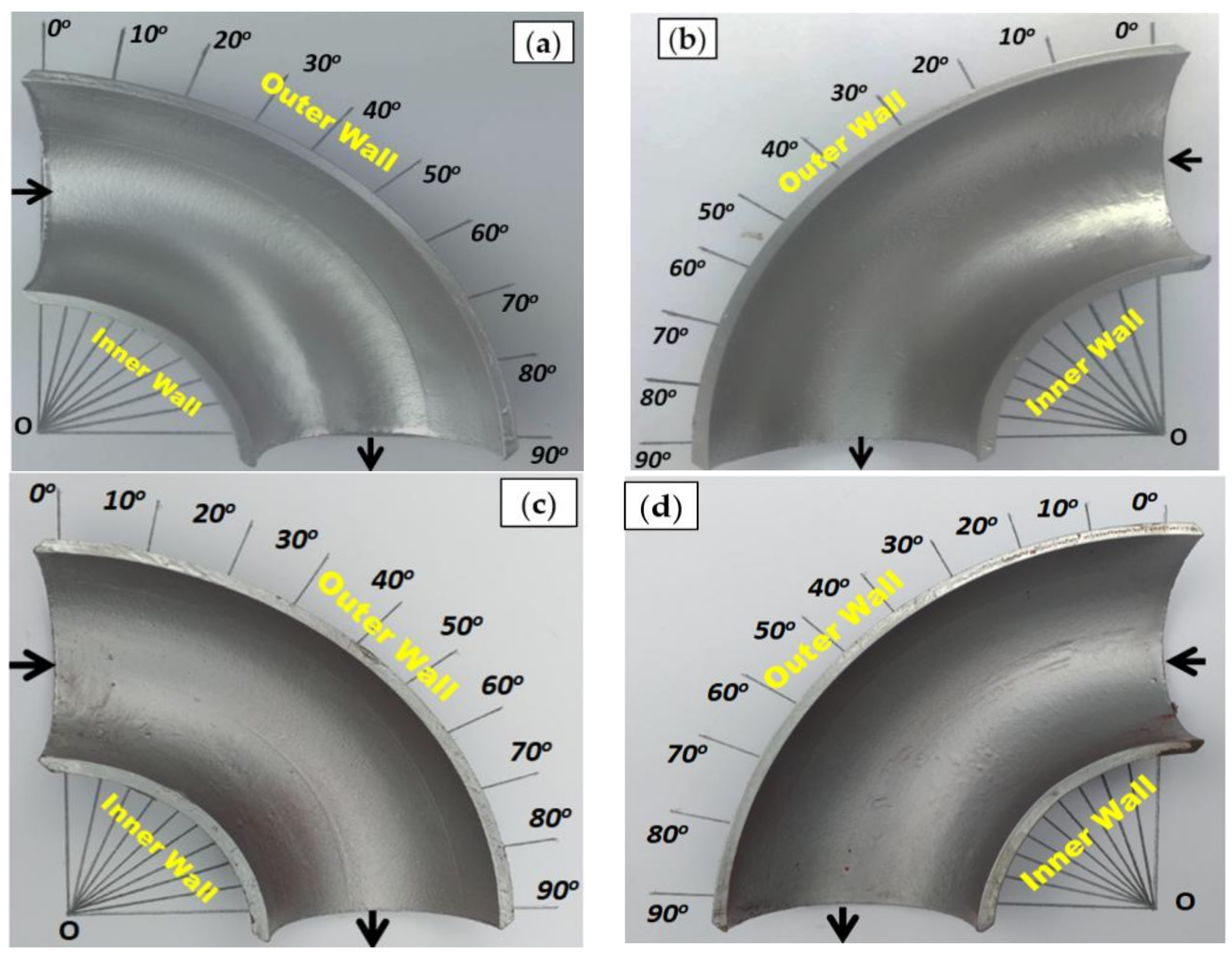
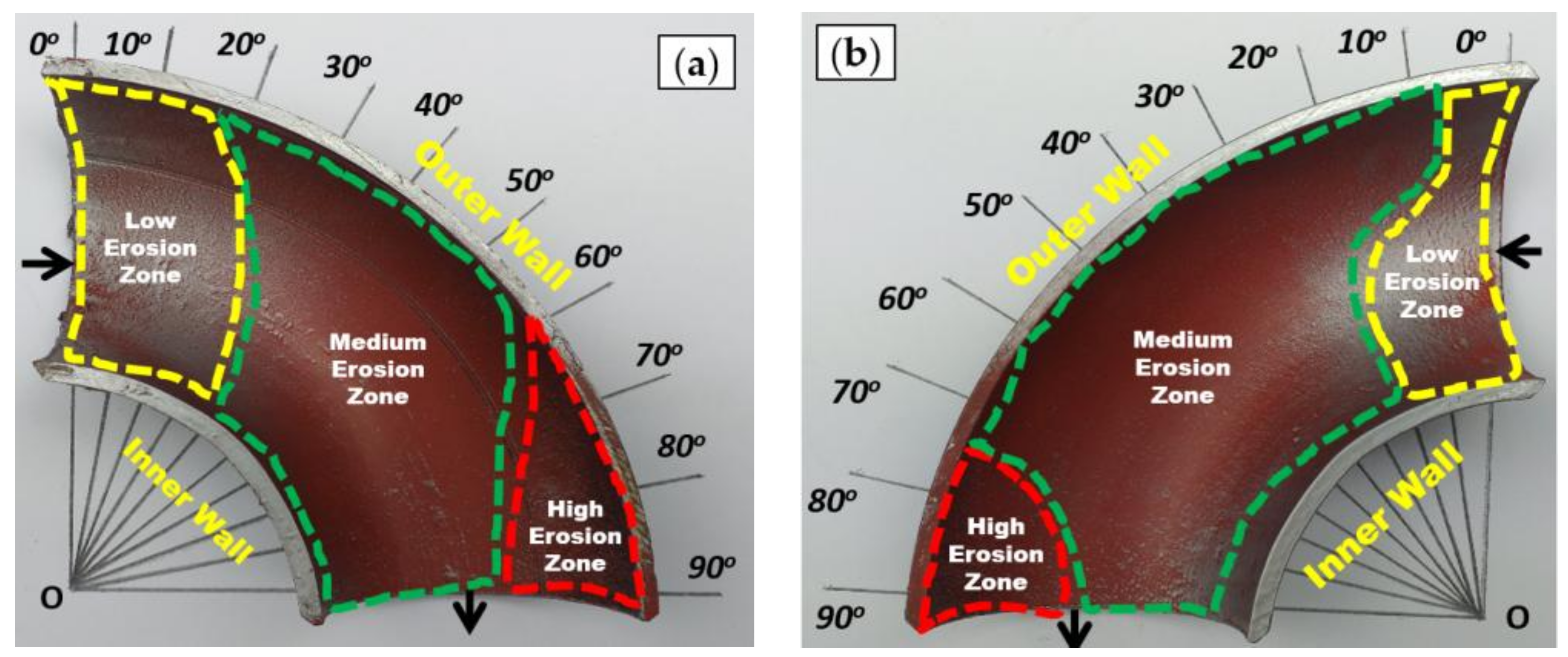
3.1. Multilayer Paint Modeling (MPM) to Determine Erosion Patterns

The multilayer paint modeling (MPM) technique adopted in this research has been used at the Flow Assurance Facility at Universiti Teknologi PETRONAS to perform erosion distribution analysis of flow changing devices for multiphase test conditions. In MPM, the erosion behavior of the multilayer paint coating under slug flow was scrutinized. In order to extract an unambiguous map of erosion hotspots, two paint coats of the red color followed by silver color were coated with a well-defined thickness on the elbow internal surface. To investigate and obtain an understanding of the influence of flow conditions on paint removal, the initial test was carried out under slug flow without sand particles for 1 h flow time.
To illustrate, Figure 4 shows the pattern of the paint removed in a 90° elbow upper half (UH) and bottom half (BH) sections after operating under slug flow conditions without abrasive medium for 1 h in a multiphase flow loop, compared to the paint removal pattern that ensued on a similar flow loop with 2% and 5% (wt/wt) sand concentrations (Figure 5 and Figure 6).
The qualitative paint removal pattern indicates that symmetrical erosion distribution was incurred around the horizontally oriented 90° elbow for erosive slug flow under 2% and 5% (wt/wt) concentrations. The qualitative results conferred in Figure 6 show that the maximum paint is removed for 5% sand concentration for slug flow, which is adequate to deduce that the location of maximum erosion adjacent to an outlet in elbow configurations are equitably well captured by the multilayer paint modeling. The low, medium, and high paint erosion locations were clearly visible in 90° elbow sections after exposure to the erosive slug flow for 2% and 5% (wt/wt) sand concentrations. The high erosion location extended between 60° and 90° with completely eroded paint in the UH and BH section (Figure 6). This indicates that severe particle impacts do occur at high sand concentration adjacent to the outlet compared to elsewhere around the 90° elbow pipe. On the other hand, a collation between the qualitative data showed that the extent of erosion developed in a 2% (wt/wt) sand concentration was significantly less compared to 5% (wt/wt) sand concentration under identical test conditions. This result encapsulates that the 2% (wt/wt) sand concentration operating condition would significantly reduce erosion in the 90° elbow pipe. Since MPM modeling showed that for 5% (wt/wt) sand concentration elbows experienced the maximum erosion-corrosion rate in contrast to that of the 2% (wt/wt) test case, further study of surface characterization and erosion-corrosion rate quantification was carried out for a 5% (wt/wt) sand concentration in slug flow. Additional observations from erosion that developed in painted elbows elucidate that severe particle-wall impaction incurred in the UH section compared to the BH section for erosive slug flow, as was also reported by Kesana et al. [26].

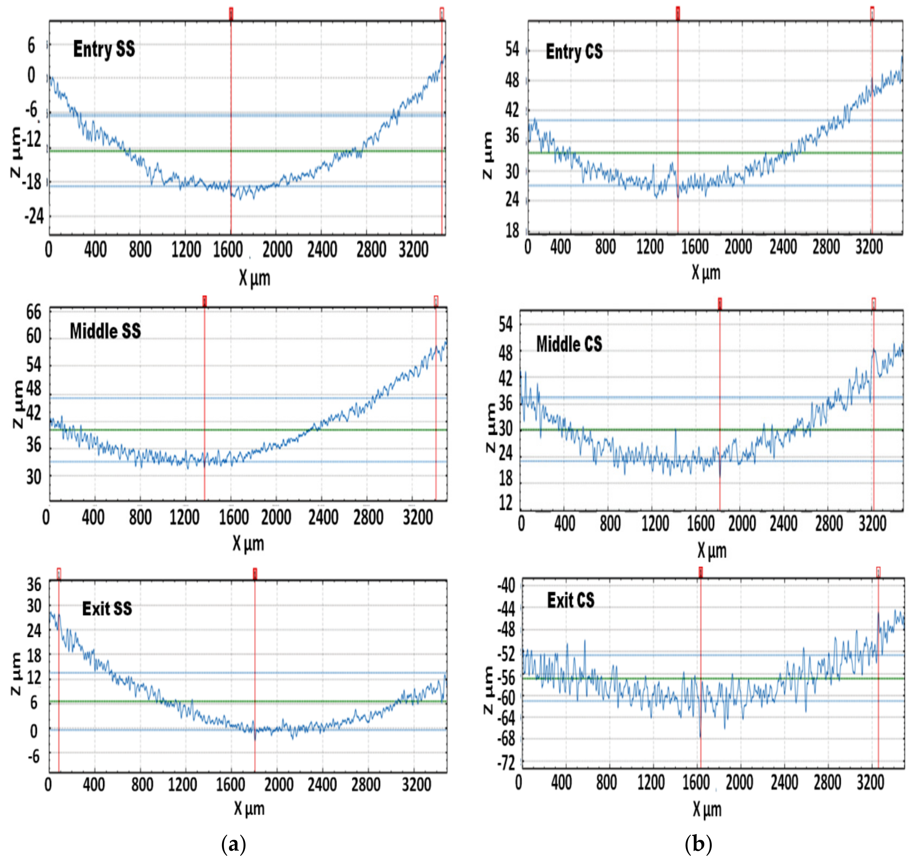
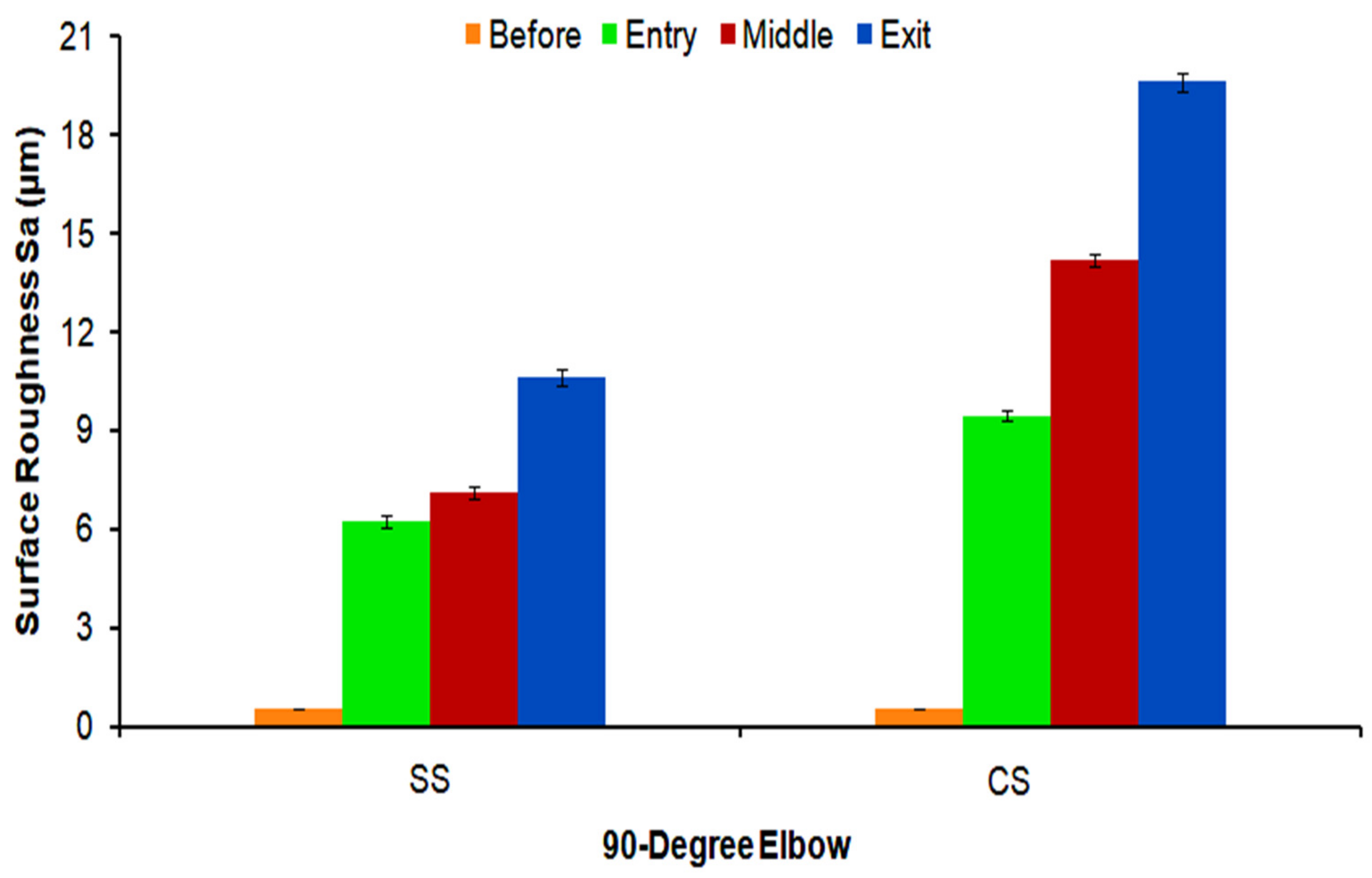
3.2. Surface Roughness

During the erosion-corrosion, the surface topology was obtained using a Sensofar confocal microscope to evaluate the deformed surface in terms of roughness and surface morphology of the inlet, middle, and outlet after 10 h of erosive slug flow exposure, while surface roughness of polished specimens was obtained from the Mitutoyo SURFTEST SJ-210 portable roughness tester (Mitutoyo Corporation, Kawasaki, Kanagawa, Japan) before the test.
Figure 7 and Figure 8 show a 3D surface roughness scan taken from non-contact surface profiling of worn surfaces of the inlet, middle, and outlet sections of elbows tested under erosive slug flow for 5% (wt/wt) sand concentration. It can be clearly seen that the exit of the 1018 CS elbow showed more cutting wear traces with several erosion-corrosion pits compared to the 304L SS elbow outlet section (Figure 7c and Figure 8c). As illustrated in Figure 7c, the extent of erosion-corrosion degradation increased with flow approaching downstream in the 1018 CS 90° elbow. This suggests that pitting action conduces to the cumulative degradation rate and could be the prevalent erosion-corrosion mechanism.
The morphology of the exit section of the 304L SS and 1018 CS 90° elbow was observed after exposure (Figure 7 and Figure 8) conformed to the state of damage accrued during the erosive slug flow impaction with the internal surface and deterioration by the erosion-corrosion process. Several features are contemplated from the micrographs of the 1018 CS elbow including ploughing, a large corrosion pit, multiple erosion scars, and the deviation in erosion or corrosion pit sizes in the inlet, middle, and outlet sections. There also appears to be a corrosion attack feature that is scrutinized in the vicinity of pits. In contrast, the 304L SS exhibited minimal wear characterized by cutting and indentation on the surface.
The micrographs of worn samples show a large erosion-corrosion pit in the 1018 CS. This indicates high material degradation since the wear disseminations reaches the substrate in the 1018 CS elbow. In comparison, there is no manifestation of the high material loss in the 304L SS elbow since the wear disseminations did not attain the substrate. The presence of these accumulated perforation sites at the exit section of the 1018 CS elbow as shown in Figure 7, lower the surface integrity because peaks and valleys could be easily eradicated due to sand impingements, and, as a result, the erosion-corrosion rate will escalate. Previous studies [2,35] investigating the relationship between surface roughness and erosion–corrosion in steel showed that the increase in roughness occurred in stainless steel because wear decreased the pitting potential, while in carbon steel an increase in the roughness enhanced the degradation rate.
The 2D roughness profile measured through the confocal topographic scan in the middle (Y = 1320 μm) of the samples over a length of 3508.8 μm is shown in Figure 9. The surface profile of 90° elbow sections after an erosion-corrosion test imparts radical information about the erosion-corrosion mechanisms of 1018 CS and 304L SS. It is observed that the alternate peak and valley pattern is very shallow at the 304L SS elbow compared to the 1018 CS elbow. At the exit section of the 90° elbow, the formation of a deep peak and valley in the direction of impact on the surface can be clearly perceived in 1018 CS as shown in Figure 9b. It is prevalent in 1018 CS compared to in 304L SS, and it is very well ratified with the microscopic observations (Figure 7c). It should be noted that inlet, middle, and outlet elbow sections exhibit different surface topographies. The differences of impact conditions in each section and material properties resulted in a different worn profile.
Figure 10 shows the variation of surface roughness on the internal surface after erosion-corrosion with flow moving downstream. After the erosion-corrosion test, the surface roughness of all the 304L SS elbow sections was discerned to be a less rough surface texture compared to the 1018 CS elbow sample as seen in Figure 10. It is recognizable that the lower extent of surface wear morphology of the 304L SS is suggestive of paramount erosion-corrosion resilience compared to the 1018 CS material. The maximum roughness (Sa) occurred at the 1018 CS elbow with a value of 19.6 ± 0.39 μm, while the maximum roughness at the exit section of 304L SS was found to be 10.62 ± 0.31 µm as shown in Table 3. Therefore, it can be elucidated that for identical conditions and geometrical shapes, the elbow exit section encounters maximum particle impaction and the mean surface roughness can be served as a consequential indication to assess the degree of aversion in erosion-corrosion. In addition, the maximum roughening occurred at the outlet for both 1018 CS and 304L SS as shown in Figure 10, which implies that the location subjected to the maximum deterioration is almost independent of the material properties.
Figure 11 presents the spectrums from the EDS (energy dispersive X-ray spectroscopy) analysis. Point scans were performed at the exit section of the elbow before the test and after the test which exhibited the sign of silicon and oxygen atoms detected after erosion-corrosion of the 1018 CS elbow. Therefore, it was confirmed that the fine sand particles were embedded on the surface after the test. EDX spectra, as shown in Figure 11, confirms the detected level of iron atoms reduced after erosion-corrosion. This suggests the presence of iron oxide deposits after the test and may lead to the formation of ferric hydroxide due to corrosion reaction and enhances localized corrosion in the carbon steel 1018 CS elbow. It is important to highlight the presence of Cr (almost 17.7 wt.%) and Ni (about 6.9 wt.%) which are primary elements that contributed to the pitting and crevice corrosion resilience of the 304L SS elbow as shown in Figure 11d.

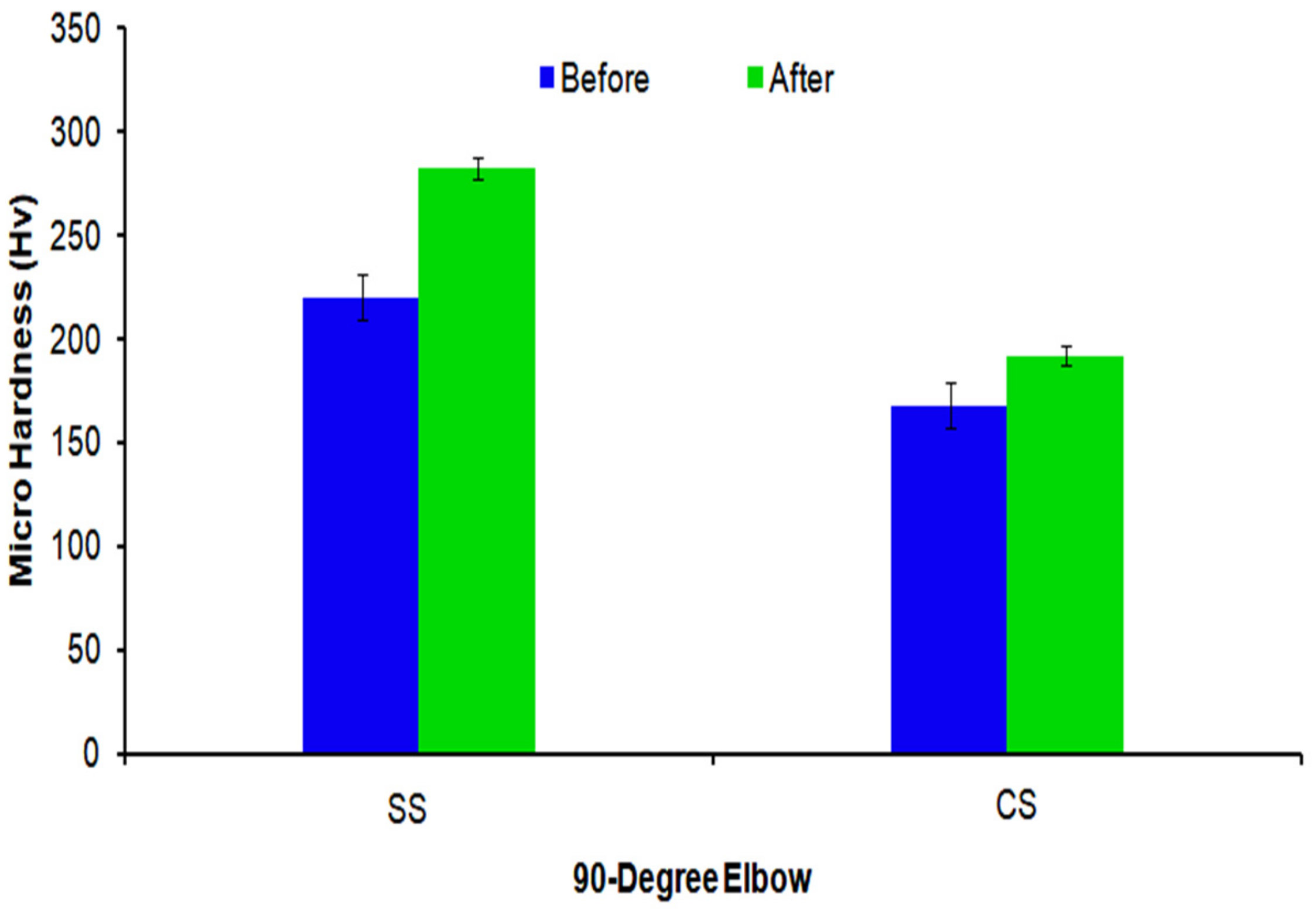
3.3. Hardness Measurements

Figure 12 presents surface hardness measurements at the downstream section of the 304L SS and 1018 CS elbows after the erosion-corrosion test. The hardness of the 304L SS elbow increased from 220 ± 8 HV to 282 ± 4 HV after the erosion-corrosion and increased from 168 ± 7 HV to 192 ± 4 HV in the 1018 CS elbow. The escalation of the material’s hardness after the particle-wall impaction is expected since the erodent impingement action strain hardened the elbow surface. It is important to note that the high level of hardness of the elbow surface could be liable for the minimal material degradation endured subsequent to erosion-corrosion in erosive slug flow. The increase of hardness may cause an increase in grain boundaries and could prevent dislocation mobility across the material [36]. Thus, inflated hardness levels led to work hardening on the internal surface and intensified the resistivity to erosion-corrosion damage. The increase in the hardness after erosion-corrosion observed in Figure 12 is consistent with the results reported in the literature [12,20].

3.4. Mass Loss

The observed mass loss of the bottom half and upper half sections of 304L SS and 1018 CS material 90° elbow with erosion-corrosion exposure is presented in Figure 13. In the present work, the mass loss of 1018 CS and 304L SS is approximately 1.4 times higher in the upper half (UH) section compared to the bottom half (BH) elbow section which may indicate high particle-wall impaction at the top of the elbow configuration, which is consistent with the results evaluated in the preceding section by the multilayer paint modeling method. Table 4 shows the mass loss per unit area after erosion-corrosion with 10 h flow time for the slug flow regime. It elucidates that for both cases, the mass loss rate in the 1018 CS elbow was 4.12 times higher than the mass-loss rate in the 304L SS elbow, which implies that 304L SS has superior erosion resistance compared to 1018 CS (Table 4). The increase in the wear rate in the 90° elbow top section observed in Figure 13 is consistent with the study by Parsi et al. [28]. The distinct variation in the mass loss rate indicates the significant role of material properties in the erosion-corrosion phenomena, which is efficacious for materials selection and assessing erosion-corrosion performance of 1018 CS and 304L SS materials flow changing devices.

4. Conclusions

The investigation of the erosion-corrosion mechanism of AISI 1018 CS and AISI 304L SS long radius 90° elbow for erosive slug flow conditions led to the following conclusions:
  • The surface roughness on the elbow internal surface is strongly influenced by the material properties for slug flow conditions. The mean surface roughness at the internal surface of the 1018 CS elbow was higher than the 304L SS elbow. This behavior of the 304L SS elbow confederates with a lower degree of surface damage.
  • From mass loss experimental data of the 1018 CS and 304L SS elbows, the erosion-corrosion rate was 4.12 times higher in the 1018 CS than the 304L SS elbow, which indicates that the 304L SS has superior erosion-corrosion resistance characteristics compared to the 1018 CS.
  • For both materials, a higher erosion-corrosion rate incurred on the upper half of the elbow compared to the bottom half, which was caused by particle impaction, which indicates the top of the elbow experienced maximum erosive wear in slug flow conditions.
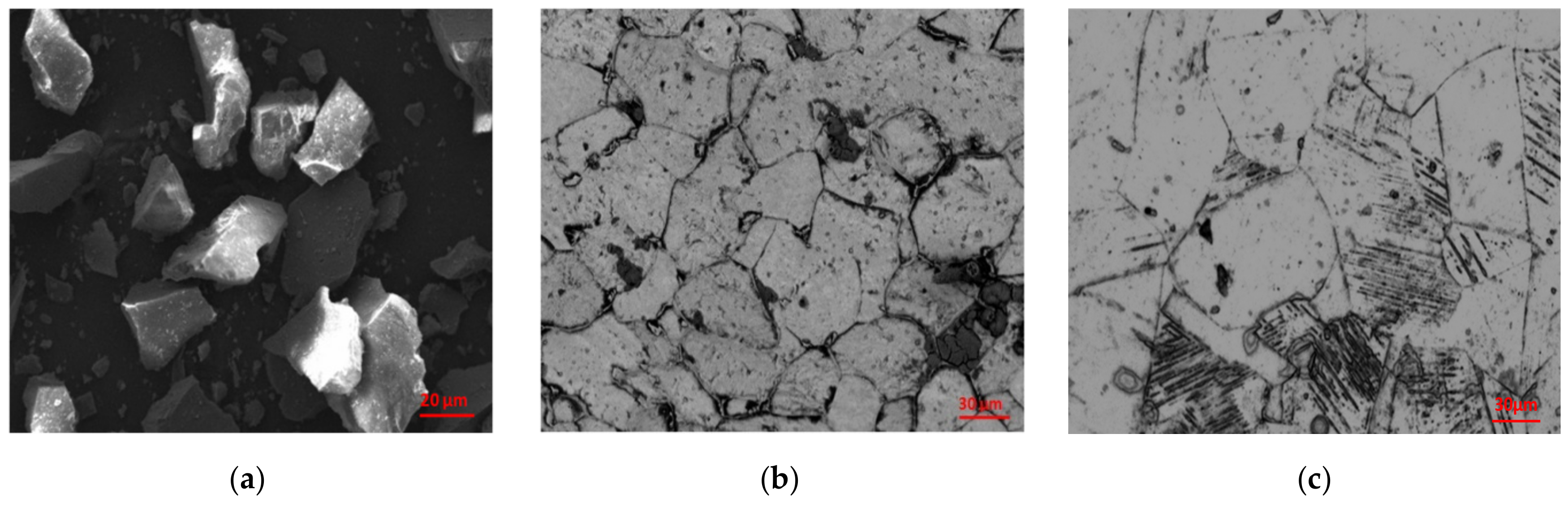
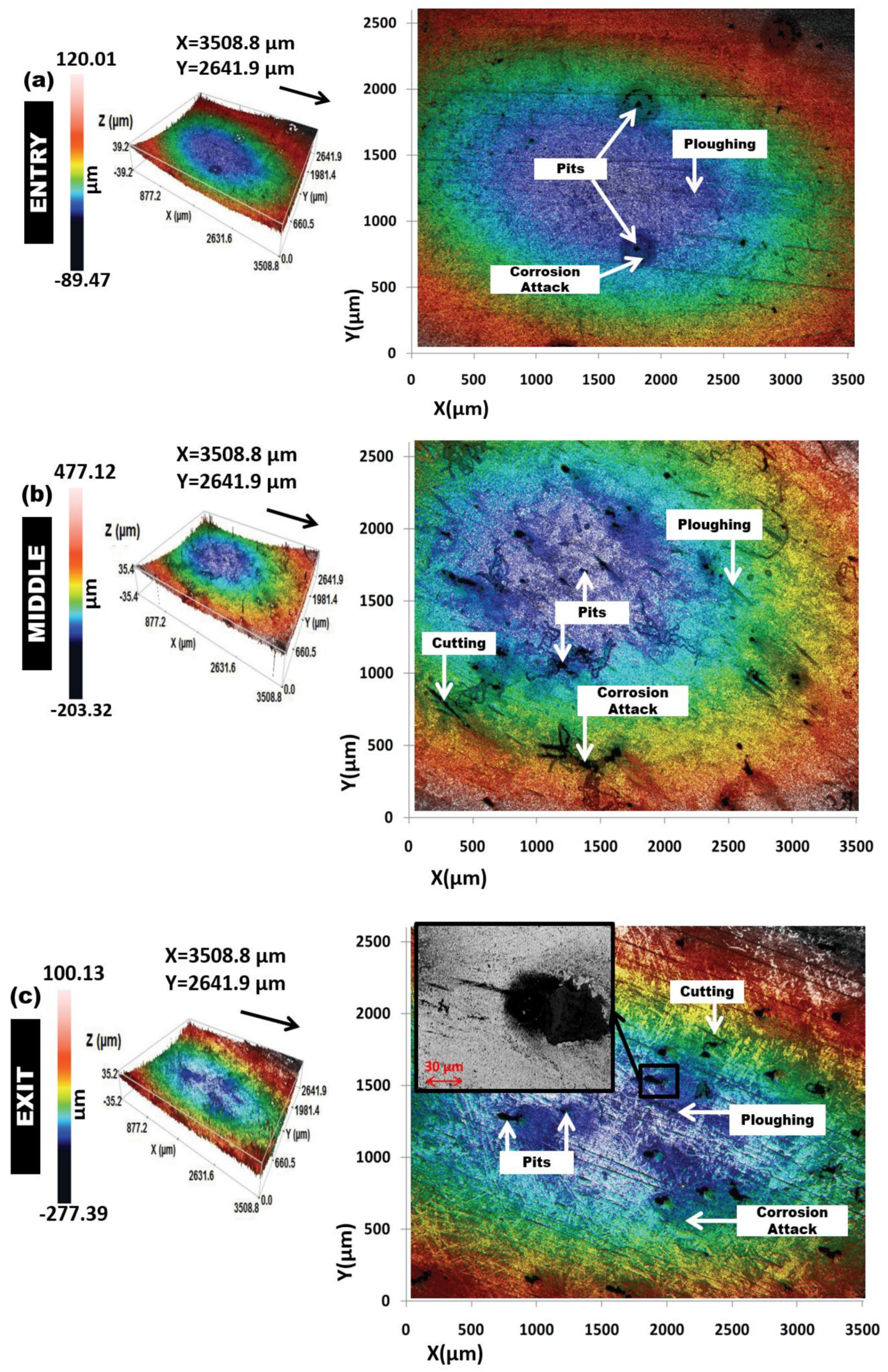
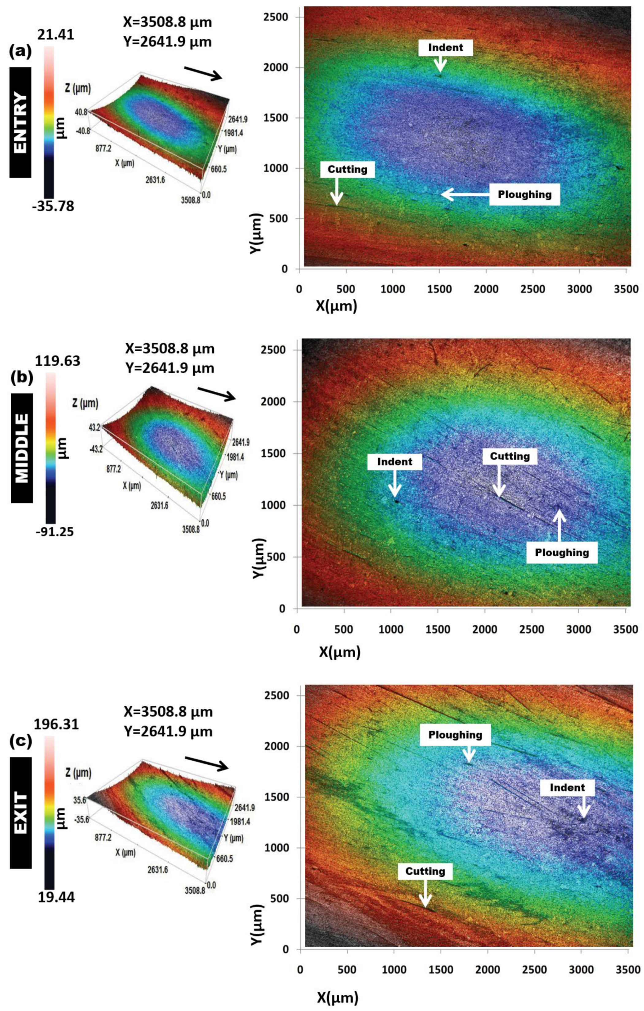
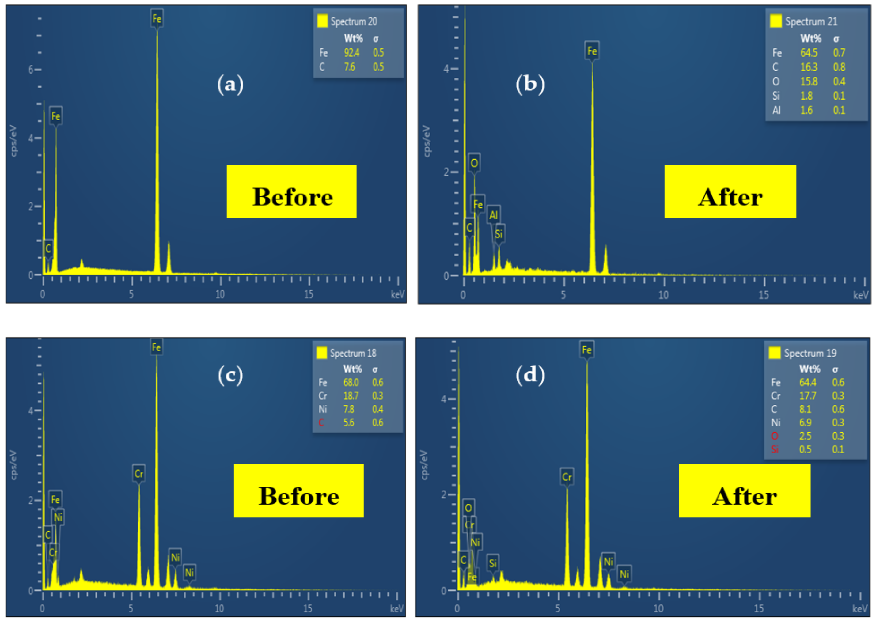
  • The erosion mechanisms ascertained in this work were ploughing, cutting, and pitting on the surface of the 1018 CS. On the other hand, the 304L SS exhibited minimal wear characterized by the cutting and indentation on the surface.
  • In erosive slug flow, a 1018 CS elbow cannot maintain the resistance to erosion-corrosion and can malfunction easily. By using the 304L SS elbow, the erosion-corrosion induced damage can be restrained and devastation can be avoided.
This work presents a comprehensive study of the erosion-corrosion degradation mechanism of 90° elbows geometry which is crucial in order to mitigate flow accelerated erosion-corrosion in working conditions. Based on the research findings, further study is recommended to fulfill the research gap identified by investigating the erosion-corrosion mechanism of 90° elbow in comparison with larger particle sizes and high sand concentrations. The working mechanism is not fully understood and requires further investigation.

Author Contributions

R.K. and H.H.Y. conceived and designed the test setup; R.K. performed the experiments, collected the required qualitative and quantitative results, and wrote the manuscript; H.H.Y. supervised the project and data analysis; W.P. guided the results analysis and route of research.

Funding

This research work was made possible by YUTP-FRG Grant 0153AA-H19 from the Universiti Teknologi PETRONAS internal research fund. The APC was funded by Universiti Teknologi PETRONAS Graduate Studies Fund and YUTP-FRG grant 0153AA-H19.

Conflicts of Interest

The authors declare no conflict of interest.

References

  1. El-Gammal, M.; Mazhar, H.; Cotton, J.S.; Shefski, C.; Pietralik, J.; Ching, C.Y. The hydrodynamic effects of single-phase flow on flow accelerated corrosion in a 90-degree elbow. Nucl. Eng. Des. 2010, 240, 1589–1598. [Google Scholar] [CrossRef]
  2. Aminul Islam, M.; Farhat, Z.N.; Ahmed, E.M.; Alfantazi, A.M. Erosion enhanced corrosion and corrosion enhanced erosion of API X-70 pipeline steel. Wear 2013, 302, 1592–1601. [Google Scholar] [CrossRef]
  3. Zhao, Y.; Zhou, F.; Yao, J.; Dong, S.; Li, N. Erosion–corrosion behavior and corrosion resistance of AISI 316 stainless steel in flow jet impingement. Wear 2015, 328–329, 464–474. [Google Scholar] [CrossRef]
  4. Liu, J.; BaKeDaShi, W.; Li, Z.; Xu, Y.; Ji, W.; Zhang, C.; Cui, G.; Zhang, R. Effect of flow velocity on erosion–corrosion of 90-degree horizontal elbow. Wear 2017, 376–377, 516–525. [Google Scholar] [CrossRef]
  5. Parsi, M.; Najmi, K.; Najafifard, F.; Hassani, S.; McLaury, B.S.; Shirazi, S.A. A comprehensive review of solid particle erosion modeling for oil and gas wells and pipelines applications. J. Nat. Gas Sci. Eng. 2014, 21, 850–873. [Google Scholar] [CrossRef]
  6. Nguyen, Q.B.; Lim, C.Y.H.; Nguyen, V.B.; Wan, Y.M.; Nai, B.; Zhang, Y.W.; Gupta, M. Slurry erosion characteristics and erosion mechanisms of stainless steel. Tribol. Int. 2014, 79, 1–7. [Google Scholar] [CrossRef]
  7. Javaheri, V.; Porter, D.; Kuokkala, V.-T. Slurry erosion of steel—Review of tests, mechanisms and materials. Wear 2018, 408–409, 248–273. [Google Scholar] [CrossRef]
  8. Ayyagari, A.; Hasannaeimi, V.; Grewal, H.S.; Arora, H.; Mukherjee, S. Corrosion, Erosion and Wear Behavior of Complex Concentrated Alloys: A Review. Metals 2018, 8, 603. [Google Scholar] [CrossRef]
  9. Elemuren, R.; Evitts, R.; Oguocha, I.; Kennell, G.; Gerspacher, R.; Odeshi, A. Slurry erosion-corrosion of 90° AISI 1018 steel elbow in saturated potash brine containing abrasive silica particles. Wear 2018, 410–411, 149–155. [Google Scholar] [CrossRef]
  10. Zeng, L.; Zhang, G.A.; Guo, X.P. Erosion–corrosion at different locations of X65 carbon steel elbow. Corros. Sci. 2014, 85, 318–330. [Google Scholar] [CrossRef]
  11. Bateni, M.R.; Szpunar, J.A.; Wang, X.; Li, D.Y. Wear and corrosion wear of medium carbon steel and 304 stainless steel. Wear 2006, 260, 116–122. [Google Scholar] [CrossRef]
  12. Rajahram, S.S.; Harvey, T.J.; Walker, J.C.; Wang, S.C.; Wood, R.J.K. Investigation of erosion–corrosion mechanisms of UNS S31603 using FIB and TEM. Tribol. Int. 2012, 46, 161–173. [Google Scholar] [CrossRef]
  13. Cheng, J.; Li, Z.; Zhang, N.; Dou, Y.; Cui, L. Experimental Study on Erosion–Corrosion of TP140 Casing Steel and 13Cr Tubing Steel in Gas–Solid and Liquid–Solid Jet Flows Containing 2 wt % NaCl. Materials 2019, 12, 358. [Google Scholar] [CrossRef] [PubMed]
  14. Li, P.; Zhao, Y.; Wang, L. Research on Erosion-Corrosion Rate of 304 Stainless Steel in Acidic Slurry via Experimental Design Method. Materials 2019, 12, 2330. [Google Scholar] [CrossRef] [PubMed]
  15. Toor, I.U.; Irshad, H.M.; Badr, H.M.; Samad, M.A. The Effect of Impingement Velocity and Angle Variation on the Erosion Corrosion Performance of API 5L-X65 Carbon Steel in a Flow Loop. Metals 2018, 8, 402. [Google Scholar] [CrossRef]
  16. Khan, M.R.; Ya, H.H.; Pao, W.; Majid, M.A.A. Numerical Investigation of Sand Particle Erosion in Long Radius Elbow for Multiphase Flow; Springer: Singapore, Singapore, 2019; pp. 41–49. [Google Scholar]
  17. Khan, R.; Ya, H.H.; Pao, W. Numerical investigation of the elbow angle effect on solid particle erosion for liquid-solid. Int. J. Mech. Mechatron. Eng. 2019, 19, 1–13. [Google Scholar]
  18. Banakermani, M.R.; Naderan, H.; Saffar-Avval, M. An investigation of erosion prediction for 15° to 90° elbows by numerical simulation of gas-solid flow. Powder Technol. 2018, 334, 9–26. [Google Scholar] [CrossRef]
  19. Solnordal, C.B.; Wong, C.Y.; Boulanger, J. An experimental and numerical analysis of erosion caused by sand pneumatically conveyed through a standard pipe elbow. Wear 2015, 336–337, 43–57. [Google Scholar] [CrossRef]
  20. Elemuren, R.; Tamsaki, A.; Evitts, R.; Oguocha, I.N.A.; Kennell, G.; Gerspacher, R.; Odeshi, A. Erosion-corrosion of 90° AISI 1018 steel elbows in potash slurry: Effect of particle concentration on surface roughness. Wear 2019, 430–431, 37–49. [Google Scholar] [CrossRef]
  21. Ishii, M.; Hibiki, T. Thermo-Fluid Dynamics of Two-Phase Flow, 2nd ed.; Springer Science & Business Media: New York, NY, USA, 2010. [Google Scholar]
  22. Vieira, R.E.; Kesana, N.R.; McLaury, B.S.; Shirazi, S.A.; Torres, C.F.; Schleicher, E.; Hampel, U. Experimental investigation of the effect of 90° standard elbow on horizontal gas–liquid stratified and annular flow characteristics using dual wire-mesh sensors. Exp. Therm. Fluid Sci. 2014, 59, 72–87. [Google Scholar] [CrossRef]
  23. Bai, Y.; Bai, Q. 13—Hydraulics. In Subsea Engineering Handbook, 2nd ed.; Bai, Y., Bai, Q., Eds.; Gulf Professional Publishing: Boston, MA, USA, 2019; pp. 315–361. [Google Scholar] [CrossRef]
  24. Coker, A.K. 4—FLUID FLOW. In Ludwig’s Applied Process Design for Chemical and Petrochemical Plants, 4th ed.; Coker, A.K., Ed.; Gulf Professional Publishing: Burlington, VT, USA, 2007; pp. 133–302. [Google Scholar] [CrossRef]
  25. Owen, J.; Ducker, E.; Huggan, M.; Ramsey, C.; Neville, A.; Barker, R. Design of an elbow for integrated gravimetric, electrochemical and acoustic emission measurements in erosion-corrosion pipe flow environments. Wear 2019, 428–429, 76–84. [Google Scholar] [CrossRef]
  26. Kesana, N.; Grubb, S.; McLaury, B.; Shirazi, S. Ultrasonic measurement of multiphase flow erosion patterns in a standard elbow. J. Energy Resour. Technol. 2013, 135, 032905. [Google Scholar] [CrossRef]
  27. Vieira, R.E.; Parsi, M.; Zahedi, P.; McLaury, B.S.; Shirazi, S.A. Sand erosion measurements under multiphase annular flow conditions in a horizontal-horizontal elbow. Powder Technol. 2017, 320, 625–636. [Google Scholar] [CrossRef]
  28. Parsi, M.; Kara, M.; Agrawal, M.; Kesana, N.; Jatale, A.; Sharma, P.; Shirazi, S. CFD simulation of sand particle erosion under multiphase flow conditions. Wear 2017, 376–377, 1176–1184. [Google Scholar] [CrossRef]
  29. Huang, H.; Tian, J.; Zhang, G.; Pan, Z. The corrosion of X52 steel at an elbow of loop system based on array electrode technology. Mater. Chem. Phys. 2016, 181, 312–320. [Google Scholar] [CrossRef]
  30. Liu, L.; Xu, Y.; Xu, C.; Wang, X.; Huang, Y. Detecting and monitoring erosion-corrosion using ring pair electrical resistance sensor in conjunction with electrochemical measurements. Wear 2019, 428–429, 328–339. [Google Scholar] [CrossRef]
  31. Wharton, J.A.; Wood, R.J.K. Influence of flow conditions on the corrosion of AISI 304L stainless steel. Wear 2004, 256, 525–536. [Google Scholar] [CrossRef]
  32. Xu, Y.; Tan, M.Y. Probing the initiation and propagation processes of flow accelerated corrosion and erosion corrosion under simulated turbulent flow conditions. Corros. Sci. 2019, 151, 163–174. [Google Scholar] [CrossRef]
  33. Khan, R. Numerical Investigation of the Influence of Sand Particle Concentration on Long Radius Elbow Erosion for Liquid-Solid Flow. Int. J. Eng. 2019, 32, 1485–1490. [Google Scholar] [CrossRef]
  34. Mandhane, J.M.; Gregory, G.A.; Aziz, K. A flow pattern map for gas—Liquid flow in horizontal pipes. Int. J. Multiph. Flow 1974, 1, 537–553. [Google Scholar] [CrossRef]
  35. Sasaki, K.; Burstein, G.T. The generation of surface roughness during slurry erosion-corrosion and its effect on the pitting potential. Corros. Sci. 1996, 38, 2111–2120. [Google Scholar] [CrossRef]
  36. Callister, W. Material Science and Engineering: An Introduction; John wiley and Sons, Inc.: New York, NY, USA, 2000; Volume 6. [Google Scholar]
Figure 1. A 90° elbow specimen. (a) As received 1018 carbon steel (CS). (b) As received 304L stainless steel (SS). (c,d) Fine polished, axially cut sections.
Metals 09 01260 g001
Figure 2. Microstructures of (a) silica sand, (b) 1018 CS, and (c) 304L SS.
Metals 09 01260 g002
Figure 3. The experimental setup used for this investigation.
Metals 09 01260 g003
Figure 4. The paint erosion pattern for slug flow with VsL = 0.5 m/s, VsG = 2.5 m/s (without sand) in a 90° horizontal-horizontal elbow section. (a) Bottom half (before test), (b) upper half (before test), (c) bottom half (after test), and (d) upper half (after test).
Metals 09 01260 g004
Figure 5. Paint erosion pattern for slug flow with 2% (wt/wt) sand concentration at VsL = 0.5 m/s, VsG = 2.5 m/s in a 90° horizontal-horizontal elbow section. (a) Bottom half and (b) upper half.
Metals 09 01260 g005
Figure 6. Paint erosion pattern for slug flow with 5% (wt/wt) sand concentration at VsL = 0.5 m/s, VsG = 2.5 m/s in a 90° horizontal-horizontal elbow section. (a) Bottom half and (b) upper half.
Metals 09 01260 g006
Figure 7. Surface topographies of 1018 CS 90° elbows after erosion-corrosion. (a) Entry section; (b) middle section; and (c) exit section.
Metals 09 01260 g007
Figure 8. Surface topographies of 304L SS 90° elbows after erosion-corrosion. (a) Entry section; (b) middle section; and (c) exit section.
Metals 09 01260 g008
Figure 9. Two-dimensional surface damage profiles of 90° elbow after erosion-corrosion: (a) 304L SS, and (b) 1018 CS.
Metals 09 01260 g009
Figure 10. Surface roughness of 304L SS and 1018 CS horizontal elbows section before and after the test.
Metals 09 01260 g010
Figure 11. Elemental phase spectra before and after the test for 1018 CS (a,b) and 304L SS (c,d).
Metals 09 01260 g011
Figure 12. Microhardness of stainless steel (SS) and carbon steel (CS) elbows before and after erosion-corrosion in erosive slug flow.
Metals 09 01260 g012
Figure 13. Mass loss in 304L SS and 1018 CS bottom half and upper half elbows section after exposure of slug flow for 10 h.
Metals 09 01260 g013
Table 1. Composition elbow material (wt.%).
1018 CS
SiCrCuPCSNiMnFe
0.260.210.250.0450.20.0350.30.5298.18
304L SS
SiCrCuPCSNiMnFe
0.3618.210.0260.020.0058.11.2372.05
Table 2. Composition of silica sand (wt.%).
SiO2Al2O3Fe2O3Na2OMgOCaO
98.081.170.280.030.220.22
Table 3. Roughness of the elbows section before and after the test.
Surface Roughness (µm)Before304L SS1018 CS
(µ ± σ)SaSaSa
Entry0.55 ± 0.026.22 ± 0.129.45 ± 0.13
Middle0.56 ± 0.037.12 ± 0.1614.2 ± 0.14
Exit0.55 ± 0.0310.62 ± 0.3119.6 ± 0.39
Table 4. Loss rates of tested 90° elbows for slug flow.
MaterialVSG (m/s)VSL (m/s)Flow Time (h)Particle Size (µm)Particle Concentration (wt.%) Mass Loss Rate (kg/m2·s)
1018 CS2.50.51050 ± 253.12 × 10⁻⁶
304L SS2.50.51050 ± 257.56 × 10⁻⁷

