1. Introduction
The discovery of superconductivity in MgB
2 in 2001 has opened new avenues of research and application of this material due to its relatively high T
C, light weight, the low cost of its constituent materials, and the absence of weak links [
1,
2,
3,
4,
5,
6,
7]. However, its large-scale commercial application depends upon the production of long wires with sufficiently high current carrying capacity using low-cost production methods. Since MgB
2 is ceramic in nature, (in situ/ex situ) powder-in-tube (PIT) is one of the simplest methods for producing cost-effective wires [
8]. In the PIT process, powder is first loaded into a metal tube and the composite assembly is mechanically worked using conventional metal working processes to produce long wires or tapes. Metal tubes, also called sheath metal, should be ductile and chemically compatible with MgB
2 [
9]. In spite their chemical suitability as sheath materials, expensive inert materials such as niobium or tantalum are not cost-effective [
10]. On the other hand, low-cost iron sheaths are found to be less reactive during the sintering process in the range of 600 to 900 °C during the formation of MgB
2. Moreover, they possess good ductility and mechanical strength for improving compaction of the MgB
2 core during the deformation of the wire [
11].
Producing long conductors requires extensive elongation of the sheath metals using processes such as swaging, wire drawing, and rolling. It is well known that plastic deformation induced by conventional forming methods such as swaging, rolling, drawing or extrusion can significantly change the mechanical properties of metals. Although these processes increase the strength, this increase in strength is nonetheless usually accompanied by the loss of ductility, making the sample prone to fracture as the number of dislocations increases.
The detrimental effects of heavy mechanical deformation may be compensated by intermediate strain-relieving annealing steps carried out at suitable temperatures for suitable durations. However, while manufacturing MgB
2 wires, it is generally not desirable to perform heat treatment processes between sequential steps of the deformation for two main reasons: First, the softening of the matrix material leads to less effective compaction of the powder and a less homogenous boundary between the powder and the tube. Second, for some matrix materials such as iron, the annealing temperature is either close to or above the temperature at which its reaction with the superconducting core starts to take place [
12,
13]. Another issue is the heat dissipation from the superconducting wires during actual practical operations. Copper, which has a much higher thermal conductivity (401 W/(m·K)) than that of iron (80.4 W/(m·K)) [
14], can efficiently dissipate heat if used as a sheath metal. However, this aspect of copper as an ideal sheath material is severely compromised due its high reactivity with the MgB
2 superconducting powder [
15].
In light of the above, we set out to develop a novel cost-effective wire processing technique for the reduction of size to as low as 1 mm without breaking which does not require intermediate strain-relief annealing. To this end, we devised a composite sheath by covering the inner iron sheath around the powder with a copper cladding. This strategy provided the strong mechanical support of the relatively inert iron while the copper cladding facilitated the efficient dissipation of the heat produced during the wire drawing process. Since sheath hybridization obviates the intermediate annealing step, it would substantially reduce processing time and greatly enhance the cost-effectiveness of the wire fabrication process. Moreover, even during an actual operation, MgB2 wire with a composite copper/iron sheath will be very effective in dissipating heat.
3. Results and Discussion
As mentioned earlier, we carefully fabricated two different kinds of superconducting MgB2 wire samples: Those with Fe sheaths and those with composite Cu–Fe sheaths. For characterization, three specimens of each sample were cut from both types of wires at different stages of the drawing process. In the following, we report the mechanical properties of the sheath as functions of diameter reduction, which of course depends upon the number of drawing steps, i.e., the amount of cold work done on the material.
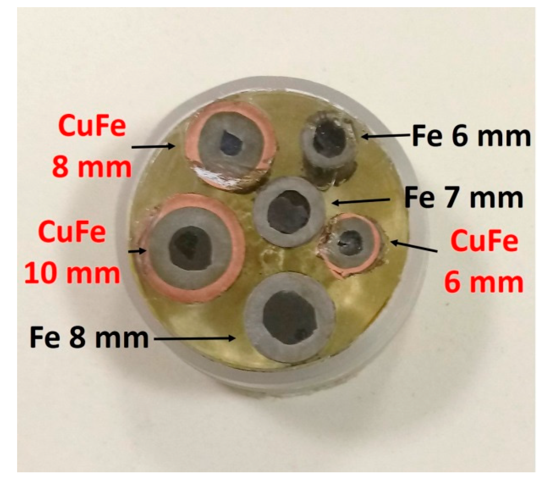
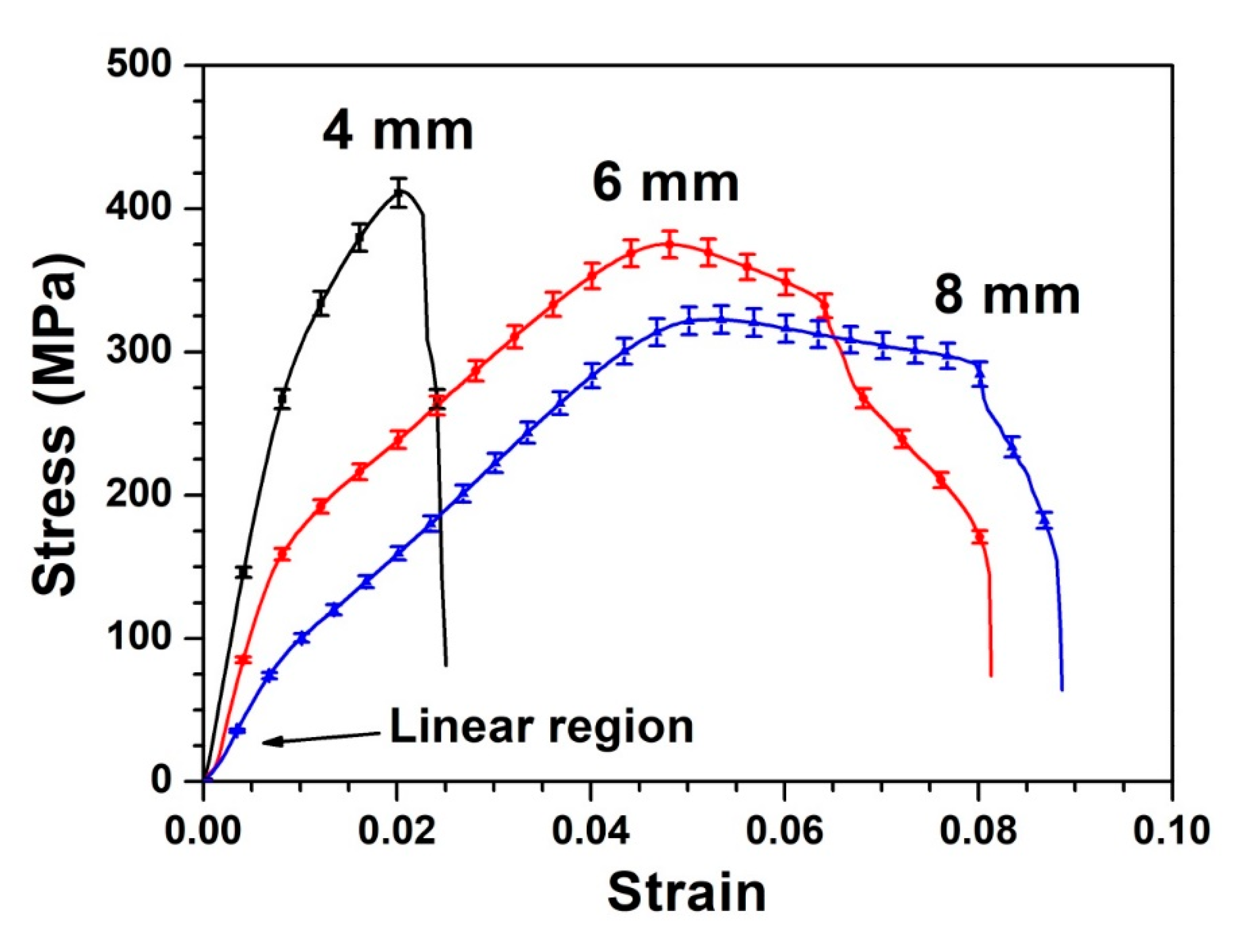
First, we show the engineering stress–strain curves for three different cases of composite Cu/Fe-sheathed MgB
2 wires in
Figure 2. Note that we started with wire with an outer diameter of 12 mm, which was gradually reduced to 6 mm. The required numbers of drawing steps were 4, 6 and 10 for reducing the size from 12 mm to 10, 8 and 6 mm, respectively. The outer diameters of the Fe sheath in these samples were 8, 6, and 4 mm, respectively. These diameters are mentioned in the legend in
Figure 2. The 8 mm sample shows a much slower response to the change in stress beyond its ultimate tensile strength (UTS). However, decreasing the diameter to 4 mm greatly affects the stress–strain behavior of the sample. In the case of the 4 mm wire, even more pronounced is the sharp decrease in the elongation of the wire until the fracture after the UTS.
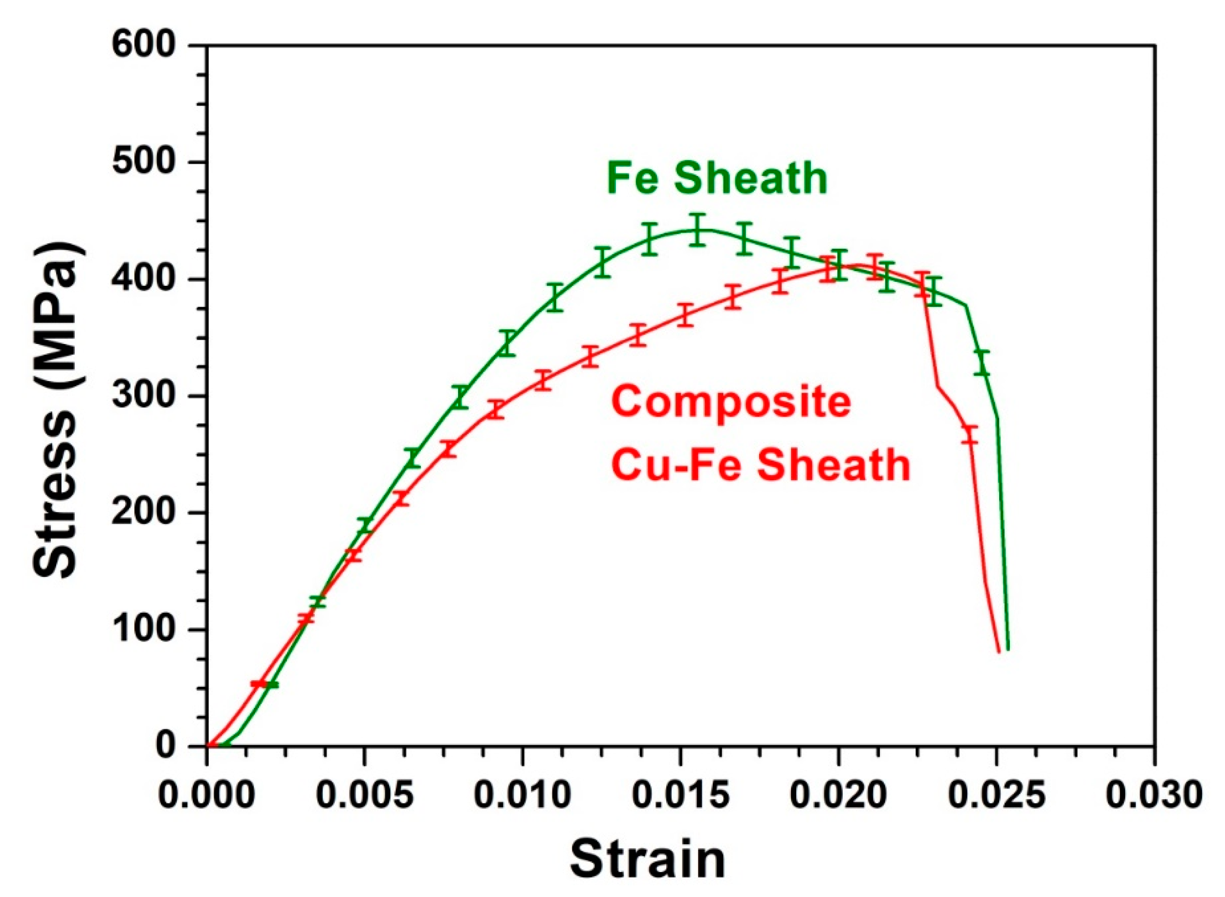
Next, the comparison between the stress–strain behaviors of both types of wire samples with 4 mm Fe sheaths is shown in
Figure 3. Note that both samples contain MgB
2 cores. The results shown in the figure are therefore composite properties of the core and the sheath material. At lower stresses, both wire samples show comparable behavior. The elastic region of the Fe-sheathed wire is much greater than that of its composite counterpart. On the other hand, the plastic region is greater in the case of the Cu–Fe-sheathed wire. Above 300 MPa, the strain values of the two samples begin to differ. At 400 MPa, the strain appears to be more than 25% higher for the Cu-Fe sheathed wire. An obvious consequence of this behavior is that our proposed Cu cladded wire is much more ductile, and therefore easier to draw compared with a wire with only a single sheath of Fe.
We carefully analyzed the stress¬–strain relationships of different samples to assess important parameters such as elastic modulus, yield strength, and ultimate tensile strength.
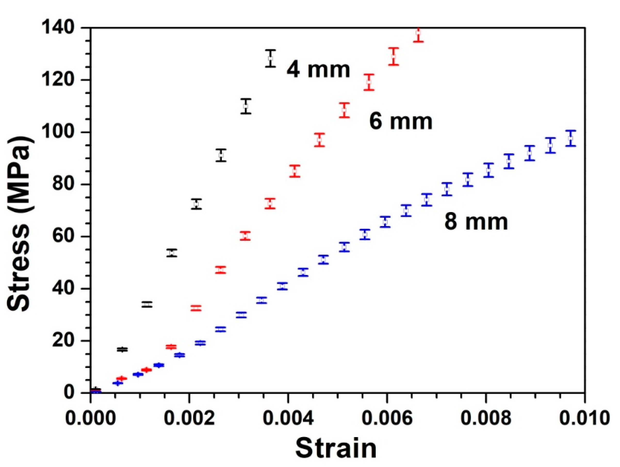
Figure 4 highlights the lower linear region, i.e., the elastic region of the stress–strain curves shown in
Figure 2. The clear increase in the slopes of the curves with the decrease in diameter is noteworthy. Note that the slope of the initial linear region of the stress–strain curve is a measure of the elastic modulus.
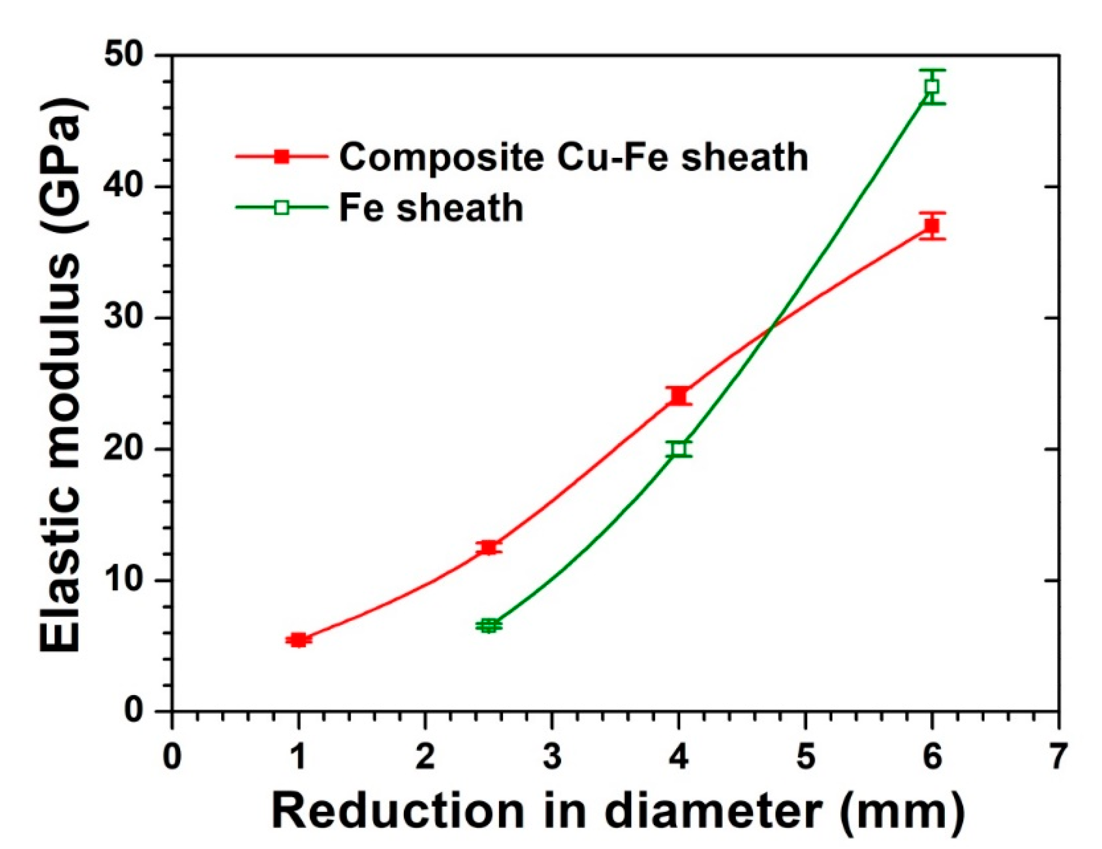
Figure 5 shows the results of the elastic modulus as a function of diameter reduction using wires at different stages of the drawing process. For both kinds of samples, the elastic modulus clearly increases with the reduction of diameter because the drawing process introduces defects into the samples, leading to an increase in the elastic modulus. The slope of the composite Cu–Fe-sheathed wire is lower than that of the Fe sheathed wire. As a consequence, owing to the decrease in elastic modulus after a certain number of drawing steps, the Cu–Fe-sheathed wire will be easier to draw than the Fe-sheathed wire and will not require an intermediate annealing step. Moreover, the final finished composite Cu–Fe wire will be easier to wind into a solenoid for use in magnetic resonance imaging (MRI) machines or other practical applications.
An important parameter of interest in the fabrication of wire is the yield point of the sheath material. In most of the stress–strain curves of our samples, the yield point was not well defined. Therefore, the offset yield strength was calculated where the stress causes a permanent strain of 0.2% [
16]. To this end, a line was drawn parallel to the linear region of the elastic limit such that it crossed the strain axis at 0.002. The point at which this line meets the stress–strain curve was taken as the offset yield strength.
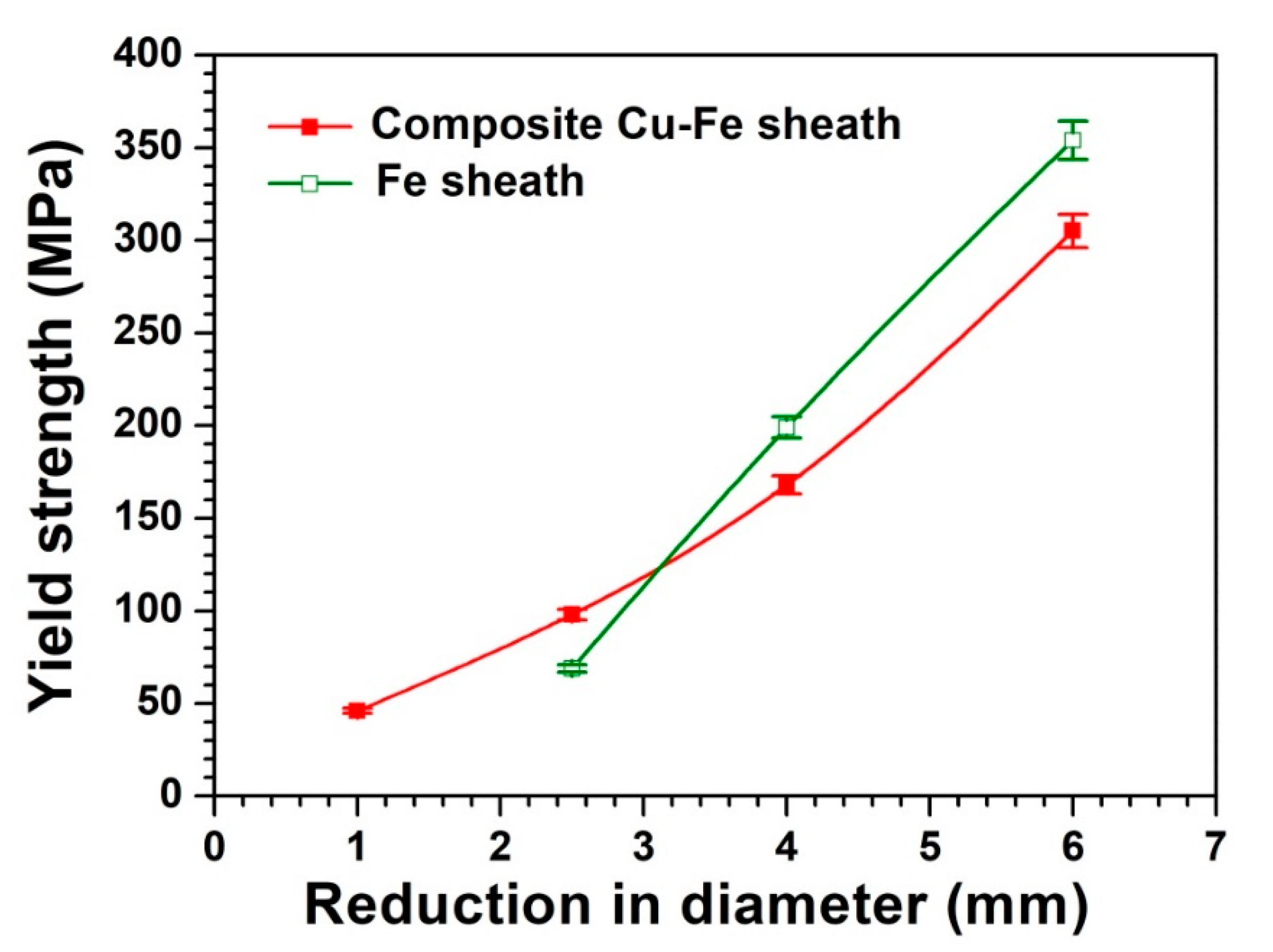
Figure 6 shows the offset yield strength for both Fe-sheathed and composite Cu/Fe-sheathed MgB
2 wires as a function of diameter reduction. A closer look at the figure reveals that Fe-sheathed wires show a higher yield strength at higher diameter reduction, which is attained only after several repeated stages of drawing. Therefore, Fe-sheathed wires would require greater loads to undergo plastic deformation in order to reduce their diameters during the process of wire drawing. Since higher stress leads to greater work hardening and greater chances of fracture, Fe-sheathed wires are at a greater risk of breakage than the composite Cu–Fe-sheathed wires [
17]. These results also indicate that the composite Cu-Fe sheathed wire could be drawn to lower diameters without any intermediate annealing process.
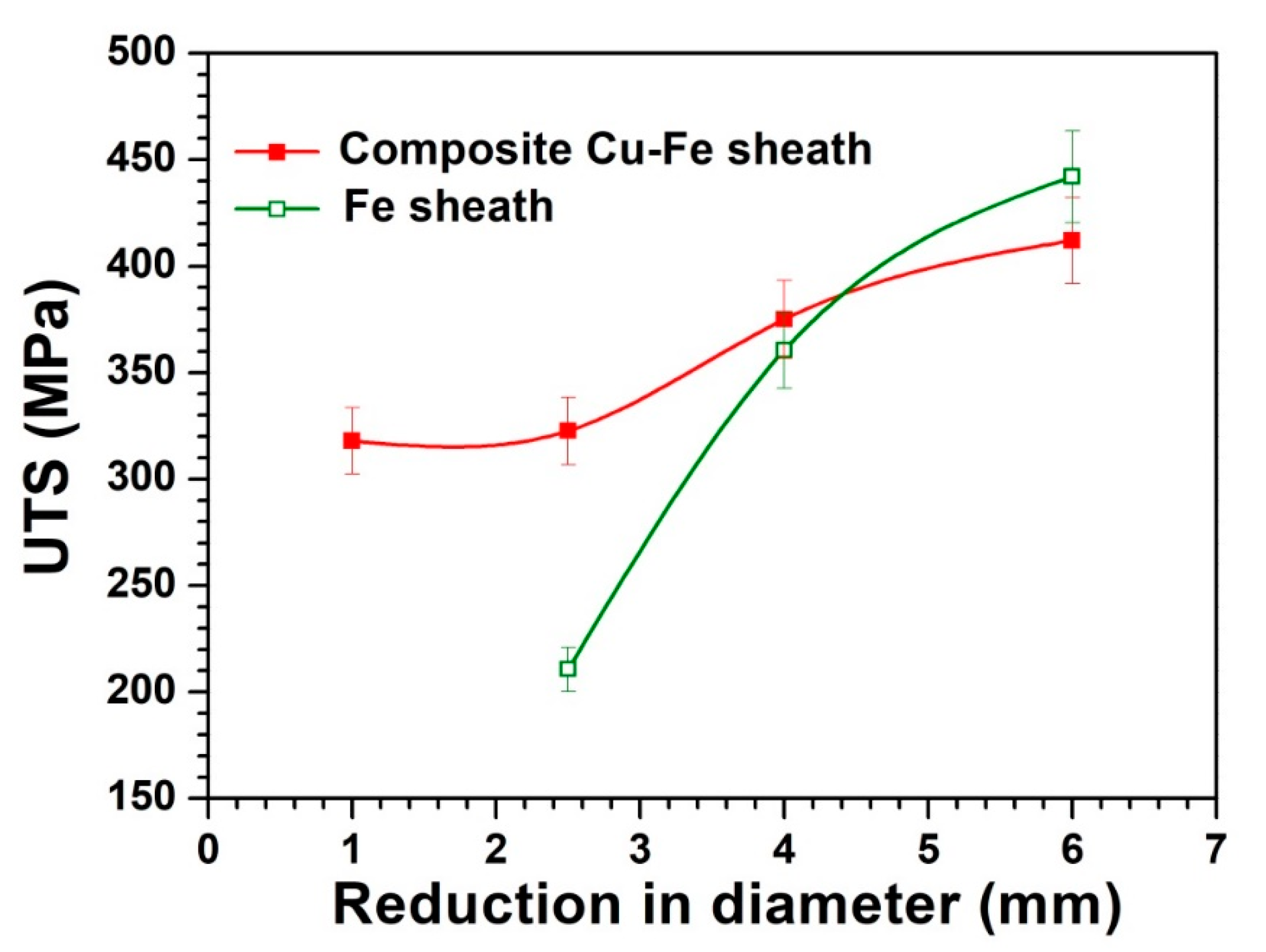
Another parameter of interest, ultimate tensile strength, was calculated from the engineering stress–strain curves and plotted as a function of wire diameter reduction, as seen in
Figure 7. In both kinds of wires, the UTS increases as the reduction in diameter increases with sequential drawing. However, the slope of the Fe-sheathed wire is much greater than that of the Cu–Fe-sheathed wire. Tensile strength is a measure of resistance to being pulled apart due to the tension. This means that composite Cu–Fe-sheathed wires required higher stress than the Fe-sheathed wires in order to undergo strain during the initial stages of drawing. It is therefore easier to pull Fe-only wires at larger diameters. But, when the wire diameter becomes smaller after several drawings, the same Fe-sheathed wire sample is relatively difficult to pull and is more prone to breaking. On the other hand, the composite Cu–Fe-sheathed wire can be drawn to a lower diameter relatively easily without breaking or requiring annealing.
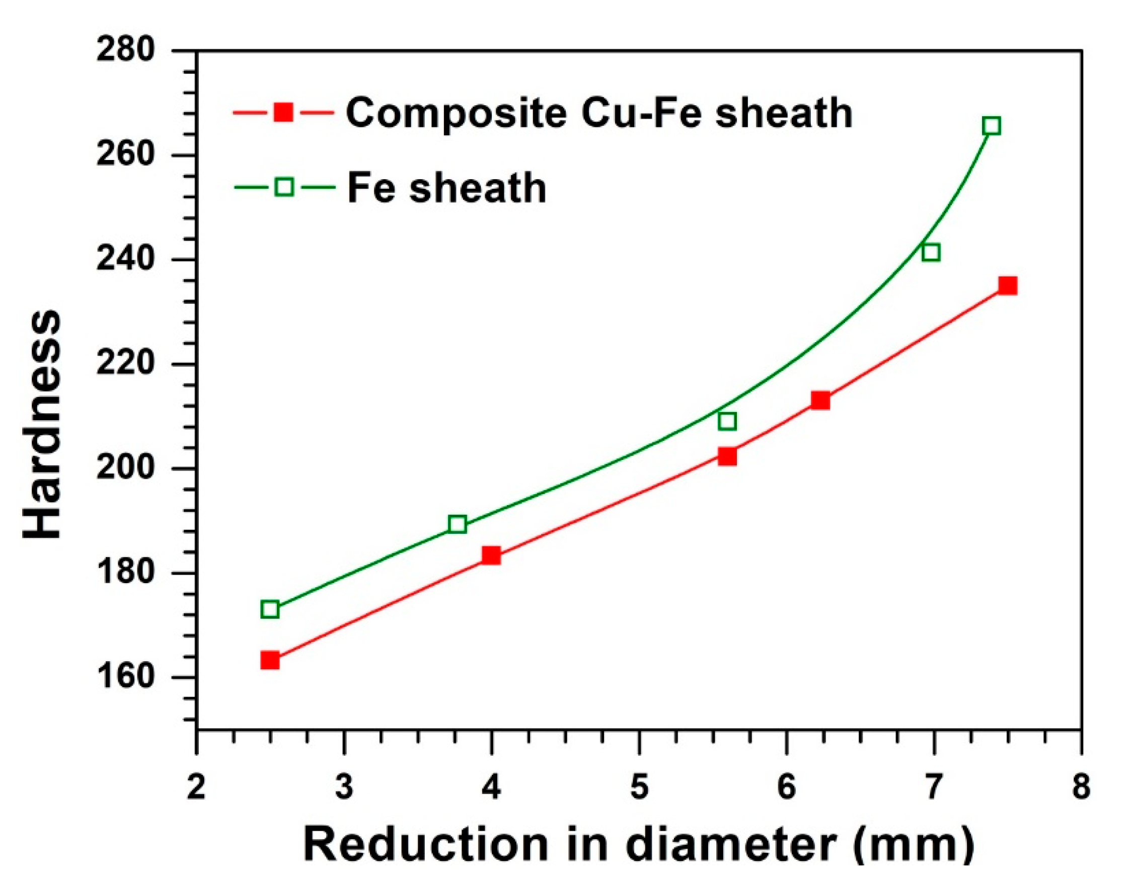
Figure 8 shows the hardness of the iron in both Fe-sheathed and composite Cu–Fe-sheathed MgB
2 wires. There is a consistent trend seen for both samples in
Figure 8. The hardness of both types of wire increases with the decrease in diameter of the wire. Additionally, the iron in the Fe-only wires is harder than the iron in the composite Cu–Fe wires. Thus, the microhardness data also indicate that the drawing of composite Cu–Fe wire is easier and less prone to the development of cracks and fractures. Hence, it can be drawn down to lower diameters without intermediate annealing. Hardness and tensile strength are generally directly proportional to one another [
18]. Hardening of the metal sheath during drawing is a result of dislocations which have accumulated in the body of the metal due to permanent plastic deformation. Although hardening due to mechanical deformation is often beneficial to some extent, too great of a degree of dislocation density certainly needs to be avoided. Dislocations mostly pile up at grain boundaries, thus accelerating the weakening of the wires and consequently decreasing their mechanical strength [
19].
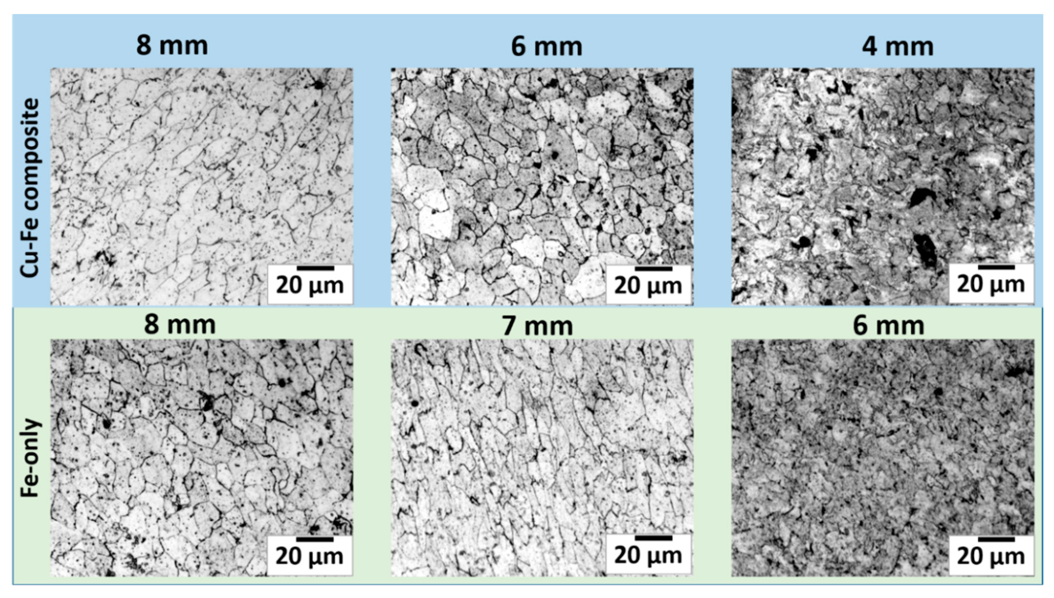
To study the effect of cold mechanical work on the grains and grain boundaries of the iron sheath—which serves as the wire’s main structural support—we investigated microstructures in both Fe-sheathed and composite Cu-Fe-sheathed wires. Results for samples of different diameters are shown in
Figure 9. Clearly, iron grains break into smaller grains under the application of huge levels of stress during the drawing process. As the diameters of the wires decrease after every stage of drawing, the grains become smaller for both types of samples.
However, composite Cu–Fe-sheathed samples undergo smaller reductions in grain size than those of Fe-sheathed samples. The grain size distribution of the 8 mm Fe-sheathed sample is comparable to that of the 6 mm composite Cu–Fe-sheathed sample. On the other hand, the 4 mm composite Cu/Fe sample has larger grains than those of the 6 mm Fe-sheath sample. These results clearly indicate that the Fe-sheathed wire has a higher rate of grain size reduction than that of the Cu–Fe-sheathed wire. Smaller grain size causes an increase in the grain boundaries, ultimately leading to more defects in the sample. These defects may hinder the sliding of slip planes over one another, which would increase the hardness and reduce the ductility of the material. As a result, the Fe-sheathed wire will show a rate of increase in hardness greater than that of its composite counterpart. Moreover, the Fe-sheath without Cu cladding is more prone to developing cracks resulting from uneven stress in the drawing process. These cracks could further propagate into larger cracks during subsequent drawing steps, eventually leading to the breaking of the wire.
The ductility of copper improves the overall malleability of the composite wire and protects the iron from fracture. The improved ductility not only prevents crack formation, but also inhibits the propagation of cracks in the Fe sheath. This could be due to the self-healing properties of such composites, where the soft copper material fills any microcracks that form in the iron sheath and prevents them from spreading [
20,
21]. This self-healing behavior is also found in laminated composites made of ceramics, metals, or polymers, where there may be single or multiple layers of different materials bonded together. This laminating effect is found to decrease the strength and increase the ductility of the composite when a ductile material is joined with a hard material. This leads to the realization of the best of both properties, namely strength and ductility. In the present work, a ductile copper layer is joined with a hard iron sheath [
22,
23,
24]. This results in improvement of mechanical properties suitable for the drawing of wire without breaking. Moreover, copper may help create a more uniform distribution of stress on the iron sheath during the hammering process in a swaging machine.
It should be noted that an intermediate annealing step would require a longer processing time and would entail a higher energy consumption during wire fabrication. On the other hand, although copper cladding will increase the material cost, its use is necessary for heat dissipation due to the magnetic flux movement that occurs during the actual practical application of the superconducting wire. Therefore, the overall manufacturing process of wire with copper cladding will be cost-effective.
Author Contributions
Conceptualization, M.S. and N.A.M.; methodology, M.S., N.A.M.; software, M.S., N.A.M.; validation, M.S., N.A.M., N.S.A.; formal analysis, M.S., N.A.M., M.A.; investigation, M.S., N.A.M., M.L., T.B.; resources, M.S., N.S.A.; experimental, N.A.M., M.L., T.B.; writing—original draft preparation, M.S., N.A.M., M.A.; writing—review and editing, M.S., M.A.; visualization, M.S., N.A.M.; supervision, M.S.; project administration, M.S., N.S.A.; Funding acquisition, M.S., N.S.A., M.A.
Funding
This research was funded by the King Abdulaziz City of Science and Technology (KACST), Saudi Arabia, through the research grant number AT 34-174.
Conflicts of Interest
The authors declare no conflict of interest.
References
- Nagamatsu, J.; Nakagawa, N.; Muranaka, T.; Zenitani, Y.; Akimitsu, J. Superconductivity at 39 K in magnesium diboride. Nature 2001, 410, 63. [Google Scholar] [CrossRef]
- Larbalestier, D.; Cooley, L.; Rikel, M.; Polyanskii, A.; Jiang, J.; Patnaik, S.; Cai, X.; Feldmann, D.; Gurevich, A.; Squitieri, A. Strongly linked current flow in polycrystalline forms of the superconductor MgB 2. Nature 2001, 410, 186. [Google Scholar] [CrossRef] [PubMed]
- Flukiger, R.; Suo, H.L.; Musolino, N.; Beneduce, C.; Toulemonde, P.; Lezza, P. Superconducting properties of MgB2 tapes and wires. Phys. C Supercond. 2003, 385, 286–305. [Google Scholar] [CrossRef]
- Alessandrini, M.; Fang, H.; Hanna, M.; Putman, P.; Zhou, Y.X.; Salama, K. High critical current of Ti-sheathed MgB2 wires for AC and weight-critical applications. Supercond. Sci. Technol. 2006, 19, 129–132. [Google Scholar] [CrossRef]
- Fang, H.; Xue, Y.Y.; Zhou, Y.X.; Baikalov, A.; Salama, K. Densification of MgB2 cores in iron-clad tapes. Supercond. Sci. Technol. 2004, 17, L27–L29. [Google Scholar] [CrossRef]
- Liang, G.; Fang, H.; Katz, D.; Tang, Z.; Salama, K. Phase formation in Cu-sheathed MgB2 wires. Phys. C Supercond. 2006, 442, 113–123. [Google Scholar] [CrossRef]
- Sumption, M.D.; Bhatia, M.; Rindfleisch, M.; Tomsic, M.; Collings, E.W. Transport properties of multifilamentary, in situ route, Cu-stabilized MgB2 strands: One metre segments and the J(c)(B, T) dependence of short samples. Supercond. Sci. Technol. 2006, 19, 155–160. [Google Scholar] [CrossRef]
- Glowacki, B.; Majoros, M.; Vickers, M.; Evetts, J.; Shi, Y.; McDougall, I. Superconductivity of powder-in-tube MgB2 wires. Supercond. Sci. Technol. 2001, 14, 193. [Google Scholar] [CrossRef]
- Schlachter, S.I.; Frank, A.; Ringsdorf, B.; Orschulko, H.; Obst, B.; Liu, B.; Goldacker, W. Suitability of sheath materials for MgB2 powder-in-tube superconductors. Phys. C Supercond. Appl. 2006, 445, 777–783. [Google Scholar] [CrossRef]
- Kovac, P.; Husek, I.; Melisek, T.; Kulich, M.; Strbik, V. MgB2 composite wires with Fe, Nb and Ta sheaths. Supercond. Sci. Technol. 2006, 19, 600–605. [Google Scholar] [CrossRef]
- Flukiger, R.; Lezza, P.; Beneduce, C.; Musolino, N.; Suo, H.L. Improved transport critical current and irreversibility fields in mono- and multifilamentary Fe/MgB2 tapes and wires using fine powders. Supercond. Sci. Technol. 2003, 16, 264–270. [Google Scholar] [CrossRef]
- Ulgen, A.T.; Belenli, I. The Effect of Fe Diffusion on Some Physical and Superconducting Properties of MgB2. J. Supercond. Nov. Magn. 2017, 30, 1089–1095. [Google Scholar] [CrossRef]
- Ulgen, A.T.; Belenli, I. Sintering Time Dependence of Iron Diffusion in MgB2 and Its Effect on Superconducting Properties. AIP Conf. Proc. 2017, 1815, 040008. [Google Scholar] [CrossRef]
- Hammond, C.R. The Elements. In Handbook of Chemistry and Physics, 81st ed.; CRC Press: Boca Raton, FL, USA, 2004. [Google Scholar]
- Wozniak, M.; Hopkins, S.C.; Gajda, D.; Glowacki, B.A. The effect of copper additions in the synthesis of in situ MgB2 Cu-sheathed wires. Phys. C Supercond. 2012, 477, 66–73. [Google Scholar] [CrossRef]
- Roylance, D.; Cohen, K.C.; Jenkins, C.H.; Khanna, S.K. Mechanics of materials: A materials science perspective. Proc. Inst. Mech. Eng. Part L J Mater. Des. Appl. 2001, 215, 141–145. [Google Scholar] [CrossRef]
- Yang, M.X.; Pan, Y.; Yuan, F.P.; Zhu, Y.T.; Wu, X.L. Back stress strengthening and strain hardening in gradient structure. Mater. Res. Lett. 2016, 4, 145–151. [Google Scholar] [CrossRef]
- Gaško, M.; Rosenberg, G. Correlation between hardness and tensile properties in ultra-high strength dual phase steels–short communication. Mater. Eng. 2011, 18, 155–159. [Google Scholar]
- Karaboğa, F.; Ulgen, A.T.; Yetiş, H.; Akdoğan, M.; Pakdil, M.; Belenli, I. Mechanical properties and uniformity of Fe-MgB2 wires upon various wire drawing steps. Mater. Sci. Eng. A 2018, 721, 89–95. [Google Scholar] [CrossRef]
- Beiermann, B.A.; Keller, M.W.; Sottos, N.R. Self-healing flexible laminates for resealing of puncture damage. Smart Mater. Struct. 2009, 18, 085001. [Google Scholar] [CrossRef]
- Sun, J.L.; Liu, C.X.; Zhang, R.; Gong, F.; Wang, C.; Li, G. Comprehensive effect of the mechanical properties, laminated structure and healing conditions on the self-healing behaviors of laminated Al2O3-MgO ceramic composites. Ceram. Int. 2019, 45, 13597–13604. [Google Scholar] [CrossRef]
- Serror, M.H.; Inoue, J. Analytical Study for Deformability of Laminated Sheet Metal with Full Interfacial Bond. J. Eng. Mech. 2013, 139, 94–103. [Google Scholar] [CrossRef]
- Qiu, Y.X.; Kaden, N.; Schmidtchen, M.; Prahl, U.; Biermann, H.; Weidner, A. Laminated TRIP/TWIP Steel Composites Produced by Roll Bonding. Metals 2019, 9, 195. [Google Scholar] [CrossRef]
- Lesuer, D.R.; Syn, C.K.; Sherby, O.D.; Wadsworth, J.; Lewandowski, J.J.; Hunt, W.H. Mechanical behaviour of laminated metal composites. Int. Mater. Rev. 1996, 41, 169–197. [Google Scholar] [CrossRef]
© 2019 by the authors. Licensee MDPI, Basel, Switzerland. This article is an open access article distributed under the terms and conditions of the Creative Commons Attribution (CC BY) license (http://creativecommons.org/licenses/by/4.0/).

 ,
, 