Abstract
Laser offset welding of 5052 aluminum to press-hardened steel using a brass interlayer was carried out. The cross-sectioned macrostructure and tensile strength were governed by varying the thickness of the brass interlayer. The maximum tensile strength reached 56.4 MPa when the thickness of brass interlayer was 0.05 mm. Subsequently, the interface microstructure, the nanoindentation characterization, and the fracture behavior were evaluated experimentally by means of scanning electron microscopy (SEM), energy-dispersive X-ray spectrometer (EDS), and micro-X-ray diffraction (micro-XRD), respectively. It was found that the intermetallic compound (IMC) layer at the interface consisted of an Fe2Al5 layer and an FeAl layer, and the estimated nanohardness of Fe2Al5, FeAl, and Fe3Al were 16.11 GPa, 9.48 GPa, and 4.13 GPa, respectively. The fracture of the joint with the 0.05 mm brass interlayer was a mixture of cleavage fracture and intergranular fracture, while that of the joint with the 0.1 mm brass interlayer exhibited the characterization of a major dendrite arm, leaving a metallurgical connected zone consisting of the Al2Cu and the α-Al phase.
1. Introduction
Welding of dissimilar metals provides a promising method and comprehensive application to take advantage of different materials. Aluminum and its alloys are widely used in modern industries due to its low density, low cost, and good corrosive properties [,,,]. In the vehicle industry, the combinatorial assemblies of aluminum and steel are effective alternatives compared with traditional steel bodies. Nevertheless, it is challenging work to achieve a sound and durable dissimilar Al-steel joint for application due to the great mismatches in melting points, thermal expansion coefficients, and thermal conductivities between steel and aluminum [,,]. On the other hand, the small amount of mutual solid solubility between steel and aluminum leads to the formation and growth of brittle intermetallic compounds (IMCs) [,,], which aggravate the mechanical properties and the quality of the welding. Therefore, it is of great significance to study the welding between steel and aluminum.
To accomplish a sound and durable joint, many attempts have been made by means of various welding methods. For example, Habibnia et al. [] studied the effect of parameters on the microstructure and mechanical properties of friction stir welded 5050 aluminum to 304 stainless steel. Zhang et al. [] reported the resistance spot welding of 6008 aluminum to H220YD galvanized steel with an AlSi12 interlayer, and obtained a maximum tensile shear strength of 6.2 kN. Cao et al. [] pointed out the good feasibility of cold metal transfer (CMT) welding-brazed aluminum to steel. Recently, laser welding was shown to exhibit an attractive perspective for joining dissimilar Al-steel joints in automotive body parts due to its advantages, including its high-power density, rapid cooling rate, short welding time, and flexibility of operation. The welds produced by laser welding have small interaction zones without any distortion, which are conducive to obtaining good weld quality. Many researchers focused on laser welding between aluminum and steel [,,,]. Narsimhachary et al. [] carried out laser brazing of aluminum 6082 to galvanized steel with the characterization of mechanical properties and microstructural analysis. Zhang et al. [] compared keyhole welding and brazing welding of aluminum to galvanized steel using the 4043 filler. They found that the thickness of the IMC layer was relatively thin, ranging from 1.5 μm to 13 μm, as the brazing welding mode was adopted. Sun et al. [] demonstrated that the mechanical strength of the Al-steel joint was determined by the brazing area. Meco et al. [] investigated the laser welding–brazing of steel to aluminum using conduction mode in a lap configuration. Meanwhile, during laser welding, it was reported that the presence of zinc suppressed the formation of brittle AlxFey [,,,].
Press-hardened steel, an advanced high-strength steel (AHSS), was extensively applied to automotive structural bodies, such as A-pillars, B-pillars, and bumpers, due to its ultra-high-strength in excess of 1500 MPa, thereby presenting as a promising lightweight material. Joining press-hardened steel and aluminum is an indispensable issue for its application as a lightweight body. A brass interlayer (Cu–Zn alloy) was considered to mitigate the growth of IMCs due to the presence of zinc, but, no literature has yet studied the laser welding of 5052 aluminum to press-hardened steel with a brass interlayer. In this study, the effect of a brass interlayer on the cross-sectioned macrostructure and mechanical properties of joints were discussed. In addition, the interface microstructure, nanoindentation characterization, and fracture behavior were evaluated experimentally.
2. Materials and Methods
2.1. Materials
The base materials selected in this paper were 5052 aluminum alloy with dimensions of 80 × 30 × 2 mm3 and press-hardened steel with dimensions of 80 × 28 × 1.3 mm3. Figure 1 shows the microstructures of two base materials. The microstructure of the press-hardened steel consisted of lath martensite (Figure 1a), causing a relatively high ultimate-strength in excess of 1500 MPa [,,]. Figure 1b shows the microstructure of 5052 aluminum. A lot of β-AlMg precipitates were homogeneously distributed on the Al matrix []. Different thicknesses of the brass interlayer were chosen as the interlayer between the aluminum alloy and the press-hardened steel. The thicknesses of the brass interlayer were 0.05 mm and 0.1 mm, respectively. Table 1 lists the chemical composition of these materials based on spark spectrometry analysis. Boron was added to the steel for the purpose of increasing its hardenability and suppressing the heterogeneous nucleation during the solidifying process [,,].
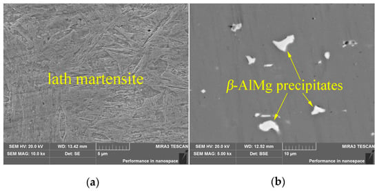
Figure 1.
The microstructure of (a) press-hardened steel and (b) 5052 aluminum alloy.

Table 1.
Chemical composition of base materials analyzed by spark spectrometry (wt%).
2.2. Experimental Details
The schematic diagrams of the laser offset welding in this study are shown in Figure 2. Fiber laser welding was employed to accomplish the welding. A butt configuration with a brass interlayer between the aluminum alloy and the press-hardened steel was tightly fixed using a clamping system. The ideal condition was having zero gap. In this investigation, the laser offset welding process was carried out by focusing the laser beam on the steel surface, because a relatively high reflectivity of aluminum resulted in an extremely low energy efficiency. The thermal source transmitted spontaneously from the steel side to the aluminum side by thermal conduction and convection, causing the fusion of the brass interlayer and the aluminum. Generally, it is of great importance to adjust the parameters to ensure the welding performance. The proper laser offset was set at 0.2 mm toward the steel side for the preliminary experimental trials. The parameters of the laser system were a power of 1.2 kW, a wavelength of 1070 nm, and a lens focal distance of 200 mm. The welding speed was set at 12 mm/s. In addition, the top and bottom shield gas flow velocities were 20 L/min and 15 L/min, respectively.
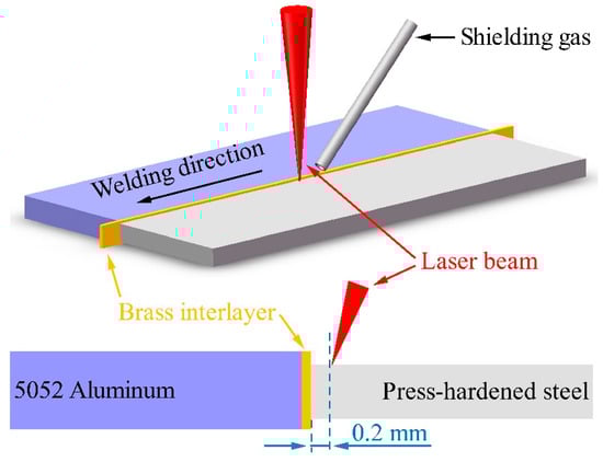
Figure 2.
Schematic diagram of the laser offset welded aluminum to press-hardened steel with a brass interlayer.
Before welding, the welding surfaces of the base materials were mechanically wiped and grinded with sandpaper to remove the oxide film. Acetone was utilized to eliminate grease and impurities. After welding, the three tensile specimens and the microstructure specimen were prepared using an electrical discharge cutting machine. The specific positions of the specimens are illustrated in Figure 3.
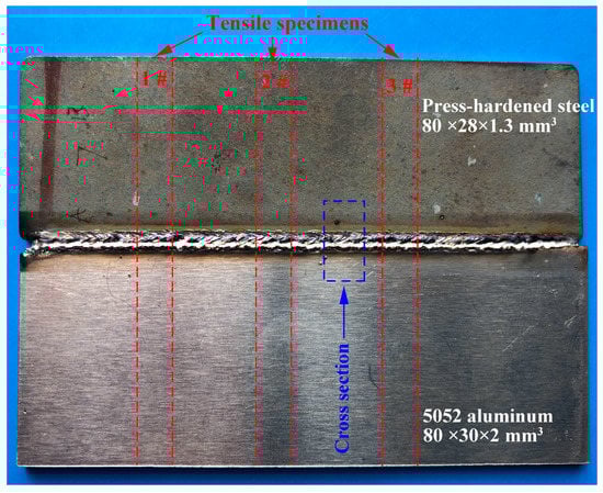
Figure 3.
Specific position of tensile specimens and cross-section.
Tensile tests were conducted using a SANS CMT5105 (Shenzhen Sans Testing Machine Co., Ltd., China) testing machine. Microstructure specimens were standardly prepared by grounding and polishing mechanically before evaluation. The cross-sectioned macrostructure, the interfacial microstructure, and fracture behavior were examined using a TESCAN MIRA3 (Tescan, Oxford, Czech Republic) scanning electron microscope (SEM) in back-scattered electron (BSE) mode. The chemical composition was revealed using an energy-dispersive X-ray spectrometer (EDS). Phase identification was conducted in depth using the Rigaku Rapid IIR (Rigaku Corporation, Tokyo, Japanese) micro-X-ray diffraction (micro-XRD) technique. The scanning speed was set at 1°/min and the scanning angle ranged from 20° to 110°. The nanoindentation hardness values of the different phases were measured using the Agilent Nano Indenter G200 (Agilent Technologies Inc., Santa Clara, USA) with a Berkovich indenter. An indenter load of 39 mN was applied so that the indenter could reach a greater depth. The resolutions of the depth and load were 0.01 nm and 50 nN, respectively.
3. Results and Discussions
3.1. Cross-Sectioned Macrostructure and Mechanical Properties
Figure 4 shows the cross-sectioned macrostructure of the welded joint with brass interlayers of 0.05 mm and 0.1 mm thicknesses, respectively. A welded nugget (WN) was formed, indicating the influence of a laser keyhole. Varying the thickness of the brass interlayer generated a different cross-sectioned macrostructure of the weld beads and weld defects. As shown in Figure 4, the concavities with different extents at the top margin of the welded nugget are displayed. The depth of concavity for the 0.05 mm brass interlayer was just 0.062 mm, while that for 0.1 mm brass interlayer was 0.14 mm. Meanwhile, the widths of the welded nugget with the 0.05 mm and 0.1 mm brass interlayers were 1.61 mm and 1.98 mm, respectively. There are two possible reasons why this may have been the case. On the one hand, the thicker interlayer retarded the heat input that was transferred to the aluminum side. The excessive heat input gradually expanded the size of molten pool, resulting in a larger contraction of the liquid wall during the solidifying process and a wider welded nugget []. On the other hand, the evaporation of the molten pool was also a significant factor during the welding process [,]. Whatever the thickness of brass interlayer was, rich-Fe isolated island particles were found near the interface or the fusion zone of the aluminum due to the vigorous stirring action in the molten pool that was induced by the laser beam [,].
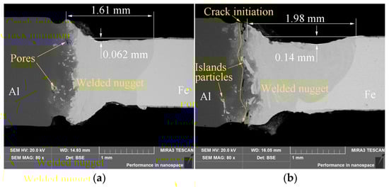
Figure 4.
Cross-sectioned macrostructure of the welded joint with different thicknesses of the brass interlayer. (a) 0.05 mm and (b) 0.1 mm.
Another interesting phenomenon was the presence of cracks, as shown in Figure 4b. The insufficient heat input was detrimental to the melting metal near the interface, which prevented the formation of a satisfactory joint. Many of these cracks were found near the interface, which provided a position susceptible to fracture. During tensile tests, it was inferred that cracks initiated from the top notch due to concentration of stress induced by the uneven distribution of residual stress, and then penetrated near the interface.
Figure 5 shows the tensile properties of the welded joints. Three specimens were utilized to measure the average value of tensile strength. The tensile strength was calculated according to the thickness of the aluminum plate. The maximum tensile strength reached 56.4 MPa when the thickness of the brass interlayer was 0.05 mm. The average value of the tensile strength decreased sharply from 52.1 MPa to 16.9 MPa when the thickness of brass interlayer increased from 0.05 mm to 0.1 mm. This was mainly attributed to the occurrence of cracks, concavity, and other defects, and was consistent with the analysis of the cross-sectional macrostructure presented above. Indeed, excessive Cu in this study may have limited the transfer of the heat input to the melting metal near the interface, but appropriate Cu may have had a strengthening function on the Fe–Al intermetallic compound [] and relaxed the residual stress []. Thus, the joint with the 0.05 mm thick interlayer had a better performance than that the 0.1 mm thick interlayer.
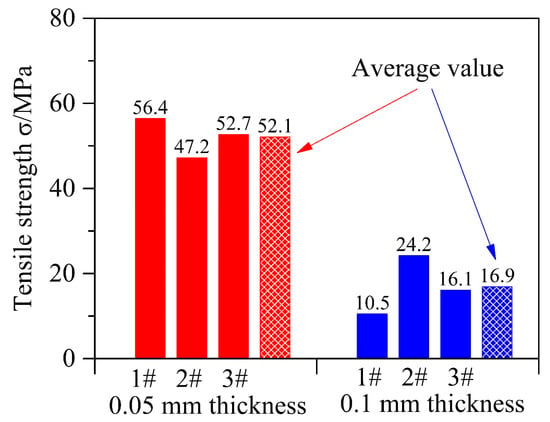
Figure 5.
Tensile properties of the welded joints with different brass interlayer thicknesses.
3.2. Interface Microstructure
In order to analyze the bonding mechanism of the joint, the interface microstructure of the joint with the 0.05 mm thick brass interlayer was examined using SEM, EDS, and micro-XRD, as shown in Figure 6. Figure 6a shows a curvilinear and complex interface with pore defects near the interface, indicating an effective weld between the aluminum and the press-hardened steel. A pore adjacent to the interface was detected, as shown in Figure 6b. The EDS results of point P1 indicated that the atom percentage was composed of 59.14% Al, 3.22% Fe, 10.52% Cu, and 25.58% Zn. It was implied that the pore was due to rapid vaporization of the zinc [,]. Distinct dendrites were embedded into the fusion zone of the aluminum, and the thickness of the dark gray IMC layer decreased from 187 μm to 59 μm.
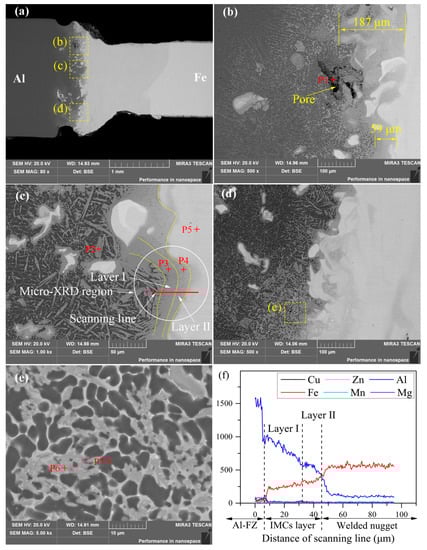
Figure 6.
Interface microstructure of the joint. (a) Cross-sectioned macrostructure of the joint, (b–d) magnified views of the regions with the dotted square in (a), (e) a magnified view of the regions with the dotted square in (d), and (f) the energy-dispersive X-ray spectrometer (EDS) result of the scanning line marked with the red line in (c).
A clear and stable IMC layer at a high magnification is shown in Figure 6c, which was divided into two layers in terms of the color variation in the BSE mode. These two layers were defined as layer I and layer II, and were marked with yellow line. The EDS results of the two layers are given in Table 2. Layer I consisted of 69.05% Al, 26.39% Fe, 0.87% Cu, and 0.34% Zn (at.%), while layer II consisted of 51.68% Al, 44.93% Fe, 1.92% Cu, and 0.31% Zn (at.%). Figure 6f shows the distribution of the main elements in the IMC layer. These results suggested that the thicknesses of layer I and II were 18 μm and 10 μm, respectively. Based on the ternary Fe–Al–Cu [] and Fe–Al–Zn systems [], it was implied that layer I and II were identified as Fe2Al5 and FeAl phases, respectively. The phase identification of the IMC layer was thoroughly confirmed via micro-XRD analysis (Figure 7). The circle region with a diameter of 100 μm, which is marked in Figure 6c, was within the measurement range for the micro-XRD analysis. Also, the acicular phases characterized a random dispersion that was inlayed into the fusion zone of the aluminum. The EDS results of point 2 indicated that this phase was composed of 76.14% Al, 21.78% Fe, 1.04% Cu, and 0.50% Zn (at.%). Therefore, the acicular phase was identified as the Fe4Al13 phase.
Table 2.
EDS results of the selected positions marked in Figure 6.
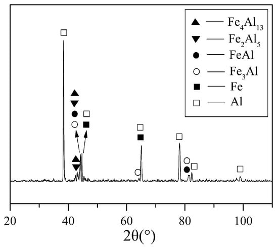
Figure 7.
Micro-X-ray diffraction (XRD) analysis of the intermetallic compound (IMC) layer.
However, the bottom microstructure was intrinsically different from the middle and top microstructures. The white phases were distributed on the gray phase matrix, thereby forming network structures near the bottom interface. The chemical composition was revealed by EDS analysis, which is displayed in Table 2. These results suggested that the white phase was the Al-rich phase Al2Cu, and the gray phase was the α-Al matrix based on the ternary Fe–Al–Cu system []. The generation of Al2Cu may have been due to the incomplete solution and diffusion of the brass interlayer in the bottom due to the rapid cooling rate and limited heat input.
3.3. Nanoindentation Characterization
In order to estimate the nanomechanical properties of the joint, nanoindentation tests were performed to precisely measure the hardness values of all of the individual regions near the interface. The recorded load–depth (P–h) curve was calculated and analyzed according to the Oliver and Pharr method []. After extracting the load–depth (P–h) curve, the nanohardness was recommended as per the following equation:
where Pmax is the maximum indentation load during the nanoindentation tests and Ac is the indentation of the projected contact area. Ac was calculated using the contact stiffness S, which was defined as .
Figure 8 shows the load–depth (P–h) curves and their corresponding indentations. As shown in Figure 8a, the P–h was divided into different stages in accordance with the load change [,,]. The first stage was the loading stage before the maximum indentation load was reached. The elastic deformation gradually decreased, whereas the plastic deformation increased. The second stage was the maintained loading stage. A short straight line occurred when the load reached the maximum value and then stayed constant for 10 s. The third was the unloading stage. The indentation load gradually reduced until it was completely unloaded. The indentation deformation consisted of the elastic–plastic loading deformation and pure elastic unloading deformation. Figure 8b shows the nanohardness values of layer I and II (i.e., Fe2Al5 and FeAl phase, see Figure 6b). The nanohardness values of Fe2Al5, FeAl, and Fe3Al were 16.11 GPa, 9.48 GPa, and 4.13 GPa, respectively. The Fe2Al5 phase possessed the greatest nanohardness but with the lowest indentation depth of 383.5 nm. This result showed that the Fe2Al5 phase was the most brittle compared to the other phases. The presence of the Fe2Al5 layer greatly deteriorated the mechanical properties of the joint. Furthermore, suppressing the formation of the brittle Fe2Al5 during the welding process was necessary to achieve a sound joint.
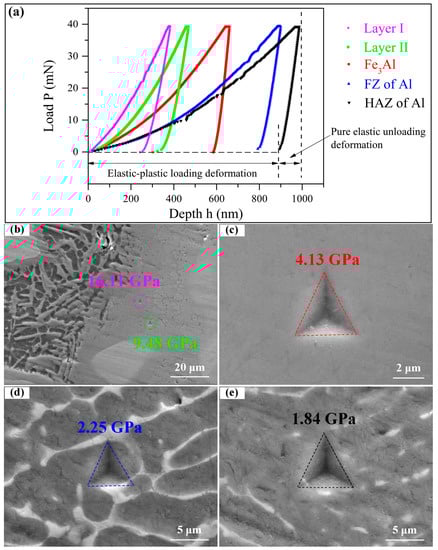
Figure 8.
Nanohardness of the welded joint. (a) Load–depth (P–h) curves and (b–e) corresponding images of indentation in all of the individual regions.
Similarly, the nanohardness values of the fusion zone (FZ) and the heat-affected zone (HAZ) of the aluminum were also measured, as shown in Figure 8d,e. The nanohardness of FZ was higher than HAZ on the aluminum side due to the grain refinement and concentrated eutectics along the grain boundary []. Compared with the load–depth curve of Fe2Al5, FeAl, and Fe3Al, the pop-in behavior was unlikely to be confirmed by observing the FZ and HAZ of aluminum. This could be attributed to the presence of white eutectics.
3.4. Fracture Behavior
Figure 9 shows the fracture surface of the welded joint with the 0.05 mm brass interlayer, corresponding to tensile specimen 1 with a maximum tensile strength of 56.4 MPa. Figure 9a shows the overall view of the joint. The fracture was slightly smooth, but pores were observed on account of vaporization of the zinc, as discussed above in Section 3.1. The magnified views of regions b and c, as marked in Figure 9a, are illustrated in Figure 9b,c, respectively. Obviously, the cleavage step, the tongue pattern, and the cracks were easily noted in Figure 9b,c, indicating a cleavage fracture. Cleavage fractures belong to brittle factures. Figure 9d shows region d, marked in Figure 9c, at a high magnification. Equiaxed grain boundaries were distinctly extracted, which is characteristic of intergranular fractures.
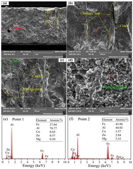
Figure 9.
Fracture surface of the welded joint with a brass interlayer of 0.05 mm. (a) Overall fracture on the aluminum side, (b,c) magnified views of the regions with the dotted square in (a), (d) a magnified view of the region with the dotted square in (d), and (e) and (f) the EDS results of point 1 and 2 as marked in (b) and (d), respectively.
In order to understand the fracture mechanism, the chemical composition of the fracture surface was examined using EDS analysis. Figure 9e shows the composition of the cleavage fracture surface (point 1). The phase appeared to be the Fe2Al5 layer, according to the atom percentage of the main elements, inferring that the fracture occurred at the Fe2Al5 layer. Figure 9f shows the composition of the intergranular fracture surface (point 2). The atom percentage was composed of 44.92% Al, 43.96% Fe, 3.57% Cu, and 2.84% Zn. It appeared that the fracture occurred at the FeAl layer. Thus, the differences in fracture characteristics were due to the Fe2Al5 and FeAl layers possessing different properties.
Figure 10 shows the fracture surface of the welded joint with the 0.1 mm brass interlayer, which corresponded to tensile specimen 2 with a maximum tensile strength of 24.2 MPa. As shown in Figure 10a, the overall fracture surface of the 0.1 mm brass was rougher than that of the 0.05 brass. The dendrite arm was detected with SEM. The EDS results of point 1 indicated that the dendrite arm was caused by the melting solidification and casting shrinkages of the aluminum. This unconnected zone also explained the fact that the mechanical performance was catastrophic. A magnified inspection of region d, as marked in Figure 10a, is given in Figure 10d. The dendrite arm and strip structures of the IMCs blended with each other. Notably, the strip structures represented the fractures of the connected zone. The EDS results of the strip structure IMCs are shown in Figure 10f. It was deduced that the metallurgical connected zone was a mixture of the Al2Cu phase and the α-Al phase.

Figure 10.
Fracture surface of the welded joint with the 0.1 mm brass interlayer. (a) Overall fracture on the aluminum side, (b,d) magnified views of the regions with the dotted square in (a), (c) a magnified view of the region with the dotted square in (b), and (e) and (f) the EDS results of point 1 and 2 as marked in (c) and (d), respectively.
4. Conclusions
Joining press-hardened steel and aluminum is an indispensable issue for applications in lightweight bodies. In this work, laser offset welding between 5052 aluminum and press-hardened steel with a brass interlayer was conducted. The mechanical properties, the interface microstructure, the nanoindentation characterization, and fracture behavior were evaluated. The following main conclusions were drawn.
- The cross-sectioned macrostructure in the weld beads and weld defects were governed by varying the thickness of the brass interlayer. The joint with the interlayer that was 0.05 mm thick had a better performance than the interlayer that was 0.1 mm thick. The maximum tensile strength reached 56.4 MPa when the thickness of the brass interlayer was 0.05 mm.
- Five IMCs were detected by evaluating the interface microstructure of the joint, including the Fe2Al5, FeAl, Fe4Al13, Fe3Al, and Al2Cu phases. The IMC layer at the interface was composed of a Fe2Al5 layer and a FeAl layer. The acicular Fe4Al13 phase displayed random dispersion inlayed into the fusion zone of the aluminum. Furthermore, the network Al2Cu phase was distributed throughout the aluminum matrix at the bottom of the interface.
- Nanomechanical properties were evaluated with nanoindentation tests. The estimated nanohardness values of Fe2Al5, FeAl, and Fe3Al were 16.11 GPa, 9.48 GPa, and 4.13 GPa, respectively. The Fe2Al5 phase possessed the greatest nanohardness and was the most brittle, which greatly deteriorated the mechanical properties.
- When the brass interlayer was 0.05 mm, the fracture mode was a mixture of cleavage fracture and intergranular fracture. The EDS analysis indicated that the cracks initiated and propagated along the interface of the Fe2Al5 layer or the FeAl layer during tensile tests. However, when the brass interlayer was 0.1 mm, melting solidification and casting shrinkages resulted in the formation of a dendrite arm, which was catastrophic in regard to mechanical performance. The remaining metallurgical connected zone consisted of the Al2Cu phase and the α-Al phase.
Author Contributions
Project administration, J.D.; investigation, X.C. and X.Z.; formal analysis, X.C. and Z.L. (Zhou Li); writing—original draft and revising, X.C.; writing—review and editing, Z.L. (Zhi Luo) and X.Z.; supervision, J.D. and Z.L. (Zhi Luo).
Funding
This work was supported by the National Key Research and Development Program of China (Grant number 2017YFB1104801).
Conflicts of Interest
The authors declare no conflict of interest.
References
- Indhu, R.; Soundarapandian, S.; Vijayaraghavan, L. Yb: YAG laser welding of dual phase steel to aluminium alloy. J. Mater. Process. Technol. 2018, 262, 411–421. [Google Scholar]
- Yan, S.; Chen, H.; Zhu, Z.; Gou, G. Hybrid laser-metal inert gas welding of Al–Mg–Si alloy joints: Microstructure and mechanical properties. Mater. Des. 2014, 61, 160–167. [Google Scholar] [CrossRef]
- Casalino, G.; Leo, P.; Mortello, M.; Perulli, P.; Varone, A. Effects of laser offset and hybrid welding on microstructure and IMC in Fe–Al dissimilar welding. Metals 2017, 7, 282. [Google Scholar] [CrossRef]
- Xue, X.; Pereira, A.; Vincze, G.; Wu, X.; Liao, J. Interfacial Characteristics of Dissimilar Ti6Al4V/AA6060 Lap Joint by Pulsed Nd: YAG Laser Welding. Metals 2019, 9, 71. [Google Scholar] [CrossRef]
- Praveen, P.; Yarlagadda, P.K.D.V. Meeting challenges in welding of aluminum alloys through pulse gas metal arc welding. J. Mater. Process. Technol. 2005, 164, 1106–1112. [Google Scholar] [CrossRef]
- Mathieu, A.; Pontevicci, S.; Viala, J.C.; Cicala, E.; Matteï, S.; Grevey, D. Laser brazing of a steel/aluminium assembly with hot filler wire (88% Al, 12% Si). Mater. Sci. Eng. A 2006, 435, 19–28. [Google Scholar] [CrossRef]
- Pardal, G.; Meco, S.; Ganguly, S.; Williams, S.; Prangnell, P. Dissimilar metal laser spot joining of steel to aluminium in conduction mode. Int. J. Adv. Manuf. Technol. 2014, 73, 365–373. [Google Scholar] [CrossRef]
- Wan, L.; Huang, Y. Microstructure and mechanical properties of Al/Steel friction stir lap weld. Metals 2017, 7, 542. [Google Scholar] [CrossRef]
- Miao, Y.G.; Chen, G.Y.; Zhang, P.; Han, D.F. Comparative Study of Bypass-Current MIG Welded–Brazed Aluminum/Galvanized Steel and Aluminum/Stainless Steel. Acta Metall. Sin. Engl. Lett. 2017, 30, 721–730. [Google Scholar] [CrossRef]
- Habibnia, M.; Shakeri, M.; Nourouzi, S.; Givi, M.B. Microstructural and mechanical properties of friction stir welded 5050 Al alloy and 304 stainless steel plates. Int. J. Adv. Manuf. Technol. 2015, 76, 819–829. [Google Scholar] [CrossRef]
- Zhang, W.; Sun, D.; Han, L.; Liu, D. Interfacial microstructure and mechanical property of resistance spot welded joint of high strength steel and aluminium alloy with 4047 AlSi12 interlayer. Mater. Des. 2014, 57, 186–194. [Google Scholar] [CrossRef]
- Cao, R.; Yu, G.; Chen, J.H.; Wang, P.C. Cold metal transfer joining aluminum alloys-to-galvanized mild steel. J. Mater. Process. Technol. 2013, 213, 1753–1763. [Google Scholar] [CrossRef]
- Narsimhachary, D.; Dutta, K.; Shariff, S.M.; Padmanabham, G.; Basu, A. Mechanical and microstructural characterization of laser weld-brazed AA6082-galvanized steel joint. J. Mater. Process. Technol. 2019, 263, 21–32. [Google Scholar] [CrossRef]
- Zhang, M.J.; Chen, G.Y.; Zhang, Y.; Wu, K.R. Research on microstructure and mechanical properties of laser keyhole welding-brazing of automotive galvanized steel to aluminum alloy. Mater. Des. 2013, 45, 24–30. [Google Scholar] [CrossRef]
- Sun, J.; Huang, J.; Yan, Q.; Li, Z. Fiber laser butt joining of aluminum to steel using welding-brazing method. Int. J. Adv. Manuf. Technol. 2016, 85, 2639–2650. [Google Scholar] [CrossRef]
- Meco, S.; Pardal, G.; Ganguly, S.; Williams, S.; McPherson, N. Application of laser in seam welding of dissimilar steel to aluminium joints for thick structural components. Opt. Lasers Eng. 2015, 67, 22–30. [Google Scholar] [CrossRef]
- Mathieu, A.; Shabadi, R.; Deschamps, A.; Suery, M.; Matteï, S.; Grevey, D.; Cicala, E. Dissimilar material joining using laser (aluminum to steel using zinc-based filler wire). Opt. Laser Technol. 2007, 39, 652–661. [Google Scholar] [CrossRef]
- Yang, J.; Li, Y.L.; Zhang, H.; Guo, W.; Zhou, Y. Control of interfacial intermetallic compounds in Fe–Al joining by Zn addition. Mater. Sci. Eng. A 2015, 645, 323–327. [Google Scholar] [CrossRef]
- Laukant, H.; Wallmann, C.; Müller, M.; Korte, M.; Stirn, B.; Haldenwanger, H.G.; Glatzel, U. Fluxless laser beam joining of aluminium with zinc coated steel. Sci. Technol. Weld. Join. 2005, 10, 219–226. [Google Scholar] [CrossRef]
- Jia, L.; Shichun, J.; Yan, S.; Cong, N.; Genzhe, H. Effects of zinc on the laser welding of an aluminum alloy and galvanized steel. J. Mater. Process. Technol. 2015, 224, 49–59. [Google Scholar] [CrossRef]
- Saha, D.C.; Biro, E.; Gerlich, A.P.; Zhou, N.Y. Fusion zone microstructure evolution of fiber laser welded press-hardened steels. Scr. Mater. 2016, 121, 18–22. [Google Scholar] [CrossRef]
- Jia, Q.; Guo, W.; Wan, Z.; Peng, Y.; Zou, G.; Tian, Z.; Zhou, Y.N. Microstructure and mechanical properties of laser welded dissimilar joints between QP and boron alloyed martensitic steels. J. Mater. Process. Technol. 2018, 259, 58–67. [Google Scholar] [CrossRef]
- Windmann, M.; Röttger, A.; Kügler, H.; Theisen, W.; Vollertsen, F. Laser beam welding of aluminum to Al-base coated high-strength steel 22MnB5. J. Mater. Process. Technol. 2015, 217, 88–95. [Google Scholar] [CrossRef]
- Sravanthi, S.S.; Acharyya, S.G.; Phani Prabhaker, K.V.; Padmanabham, G. Integrity of 5052 Al-mild steel dissimilar welds fabricated using MIG-brazing and cold metal transfer in nitric acid medium. J. Mater. Process. Technol. 2019, 268, 97–106. [Google Scholar]
- Huang, L.; Hua, X.; Wu, D.; Li, F. Numerical study of keyhole instability and porosity formation mechanism in laser welding of aluminum alloy and steel. J. Mater. Process. Technol. 2018, 252, 421–431. [Google Scholar] [CrossRef]
- Wang, P.; Chen, X.; Pan, Q.; Madigan, B.; Long, J. Laser welding dissimilar materials of aluminum to steel: An overview. Int. J. Adv. Manuf. Technol. 2016, 87, 3081–3090. [Google Scholar] [CrossRef]
- Wahba, M.; Katayama, S. Laser welding of AZ31B magnesium alloy to Zn-coated steel. Mater. Des. 2012, 35, 701–706. [Google Scholar] [CrossRef]
- Chen, S.; Zhai, Z.; Huang, J.; Zhao, X.; Xiong, J. Interface microstructure and fracture behavior of single/dual-beam laser welded steel-Al dissimilar joint produced with copper interlayer. Int. J. Adv. Manuf. Technol. 2016, 82, 631–643. [Google Scholar] [CrossRef]
- Hosseini, S.R.E.; Feng, K.; Nie, P.; Zhang, K.; Huang, J.; Chen, Y.; Shu, D.; Li, Z.; Guo, B.; Xue, S. Fracture surface characterization of laser welding processed Ti alloy to stainless steel joints. Weld. World 2018, 62, 947–960. [Google Scholar] [CrossRef]
- Yang, S.; Zhang, J.; Lian, J.; Lei, Y. Welding of aluminum alloy to zinc coated steel by cold metal transfer. Mater. Des. 2013, 49, 602–612. [Google Scholar] [CrossRef]
- Mei, L.; Chen, G.; Jin, X.; Zhang, Y.; Wu, Q. Research on laser welding of high-strength galvanized automobile steel sheets. Opt. Lasers Eng. 2009, 47, 1117–1124. [Google Scholar] [CrossRef]
- Chen, H.L.; Du, Y.; Xu, H.; Xiong, W. Experimental investigation and thermodynamic modeling of the ternary Al–Cu–Fe system. J. Mater. Res. 2009, 24, 3154–3164. [Google Scholar] [CrossRef]
- Raghavan, V. Phase Diagram Updates and Evaluations of the Al-Fe-P, B-Fe-U, Bi-Fe-Zn, Cu-Fe-Zn, Fe-Si-Zn and Fe-Ti-V Systems. J. Phase Equilib. Diffus. 2013, 34, 230–243. [Google Scholar] [CrossRef]
- Oliver, W.C.; Pharr, G.M. An improved technique for determining hardness and elastic modulus using load and displacement sensing indentation experiments. J. Mater. Res. 1992, 7, 1564–1583. [Google Scholar] [CrossRef]
- Liu, G.; Hu, X.; Fu, Y.; Li, Y. Microstructure and mechanical properties of ultrasonic welded joint of 1060 aluminum alloy and T2 pure copper. Metals 2017, 7, 361. [Google Scholar] [CrossRef]
- Li, C.; Zhang, F.; Wang, X.; Rao, X. Investigation on surface/subsurface deformation mechanism and mechanical properties of GGG single crystal induced by nanoindentation. Appl. Opt. 2018, 57, 3661–3668. [Google Scholar] [CrossRef]
- Pham, T.H.; Kim, S.E. Determination of mechanical properties in SM490 steel weld zone using nanoindentation and FE analysis. J. Constr. Steel. Res. 2015, 114, 314–324. [Google Scholar] [CrossRef]
- Cabibbo, M.; Forcellese, A.; El Mehtedi, M.; Simoncini, M. Double side friction stir welding of AA6082 sheets: Microstructure and nanoindentation characterization. Mater. Sci. Eng. A 2014, 590, 209–217. [Google Scholar] [CrossRef]
© 2019 by the authors. Licensee MDPI, Basel, Switzerland. This article is an open access article distributed under the terms and conditions of the Creative Commons Attribution (CC BY) license (http://creativecommons.org/licenses/by/4.0/).