Article

Experimental and Numerical Investigation on the Layering Configuration Effect to the Laminated Aluminium/Steel Panel Subjected to High Speed Impact Test

by
Najihah Abdul Rahman
1,*,
Shahrum Abdullah
1,*,
Mohamad Faizal Abdullah
2,
Wan Fathul Hakim Zamri
3,
Mohd Zaidi Omar
3 and
Zainuddin Sajuri
3
1
Centre for Integrated Design for Advanced Mechanical Systems, Faculty of Engineering and Built Environment, Universiti Kebangsaan Malaysia, Bangi 43600, Selangor, Malaysia
2
Department of Mechanical Engineering, Faculty of Engineering, Universiti Pertahanan Nasional Malaysia, Kem Sg Besi, Kuala Lumpur 57000, Malaysia
3
Centre for Materials Engineering and Smart Manufacturing, Faculty of Engineering and Built Environment, Universiti Kebangsaan Malaysia, Bangi 43600, Selangor, Malaysia
*
Authors to whom correspondence should be addressed.
Metals 2018, 8(9), 732; https://doi.org/10.3390/met8090732
Submission received: 16 August 2018 / Revised: 14 September 2018 / Accepted: 14 September 2018 / Published: 17 September 2018

Abstract

:
This paper presents the effect of laminated aluminium-steel panel with different configurations in a high-speed impact test. Layering aluminium plate with high strength steel has become an interest in reducing the overall density of armour vehicle body while improving the ballistic resistance. Different layering configurations differ in laminated panel performance. Two layering configurations of double-layered panel achieving 25% of existing panel weight reduction were tested using experiment and computational method to investigate their behaviours when impacted with 7.62-mm full metal jacket at velocity range of 800–850 m/s. The ballistic performance of each configuration plate in terms of ballistic limit velocity, penetration process and permanent deformation was quantified and considered. Laminated panel with aluminium as the front layer reduced the ballistic performance of existing panel to 50% and the other panel maintained its performance. Thus, the laminated panel with aluminium as the back layer can be used in designing a protective structure for armoured vehicle while maintaining the performance of the existing vehicle in achieving weight reduction.

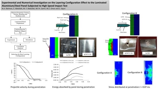
Graphical Abstract

1. Introduction

Material failure characterisation can be determined using several methods and engineering methods, such as using the finite element analysis. The finite element method is an analysis to predict the state of a product or material when encumbered to test the strength of the material before it fails. The penetration depth of the material, as one example of the failure of the material when subjected to a high-speed impact, can be analysed using this method. High-speed impact, also known as ballistic impact, is one of the measures used to determine the material resistance to prevent the projectile from penetrating the panel [1]. Failure of a material by ballistic impact is influenced by several factors such as the projectile nose shape, projectile materials, impact velocity, panel layering configuration and mechanical properties of materials constituting the laminated panel [2]. The ballistic test is often performed to test the strength of the materials used in military applications such as vehicle panel shield [3]. The use of a single material made of armour steel has been widely used as the main material in designing armoured vehicle panel due to the combined features of high strength, toughness, good formability, weldability and excellent ballistic performance [4]. However, the disadvantage of this material is from the point of its heaviness. Weight is an important parameter in the manufacture of armoured vehicles because higher weight leads to higher energy consumption to drive the vehicle and more difficulty in manoeuvring the vehicle on challenging topography [5]. Therefore, many studies have been done to reduce the weight of the materials used in these applications. One way to achieve lighter weight is to combine two different types of materials by laminating the light weight material with the existing steel.
According to previous studies, most researchers found that the single material of armour steel provided better ballistic performance compared to the layered material. Børvik et al. [6] conducted a study on the ballistic performance of the layered material and compared it with a panel of single material using Weldox 700E. The result showed that monolithic panel of same thickness and material has better performance compared to the layered panel as a result of reduction in the structure leading to substantiality of bending behaviour. Restriction of vehicle manoeuvrability due to heaviness characteristics of an armoured vehicle has directed researchers to study the performance of lightweight materials under ballistic impact. Wei et al. [7] also concluded that achievement of ballistic impact of monolithic lightweight materials has been found to be always better than the layered panel of similar material and thickness. However, monolithic lightweight materials such as aluminium alloy panel could not give a comparable ballistic performance with monolithic existing armour steel panel.
It has been suggested that the ballistic performance of an aluminium alloy can be improved by layering the alloy with the existing armour steel as a laminated panel. Gupta et al. [8] suggested that the performance of aluminium panel with various thicknesses and layering configurations gave different performance. Forrestal et al. [9] reported the performance of laminated armour steel and aluminium alloys of Al7075-T6 and Al5083-H116 can be integrated with armour steel to serve as vehicle protective structures and demonstrated relatively good performance as existing material. Flores-Johnson et al. [10] performed finite element analysis of the impact of a 7.62 mm APM2 projectile on multi-layered armour plates to investigate the effect of different layer configurations, thicknesses and material properties on ballistic performance. Übeyli et al. [11] investigated the effect of laminate configuration on the behaviour of aluminium laminated composite against 7.62 AP projectiles and found that using hard material on the first layer and aluminium alloy on the back layer can improve the ballistic performance of armour steel. Layering configuration is one of the important parameters affecting the ballistic performance of a laminated dissimilar metal panel. Moreover, researchers recently focused on implementing finite element method to study the behaviour of multi-layered panels consisting of aluminium alloys and steels under high velocity impact.
The literature shows that the penetration effects of multi-layered panels are categorised as a complex problem. For the design of a ballistic resistant panel, the factors such as layer configurations and thickness should be well considered to obtain optimum protective structures. Since different layering configuration would give different ballistic performance, the study for different layering configuration has become necessary to find the best configuration as an option for an armoured vehicle application. Therefore, the aim of this study is to analyse the effect of different layering configuration to the failure of the laminated panel in terms of permanent deformation and penetration process using both experiment and simulation approaches. The study performed on a double-layered panel consisting two different materials, aluminium alloy Al7075-T6 and steel Ar500 which has similar total weights and initial impact velocities but different layering configuration. Double-layered panels were subjected to the ballistic tests using powdered gun and the tests then were simulated using an explicit non-linear finite element program against a 7.62-mm FMJ projectile at a velocity of 800–850 m/s. The ballistic performance of laminated layered plates made of combination of Ar500 steel and Al7075-T6 was evaluated based on the perforation mechanism, the depth of penetration and the crater diameter.

2. Materials and Method

The methodology framework used in this study is given in Figure 1. Combination of Ar500 steel and Al7075-T6 aluminium is an interesting option leading to weight-saving and ballistic performance improvement based on their material properties in terms of tensile strength, bending strength and hardness. At first, the mechanical tests by means of the tensile, bending and hardness tests were conducted to find the respective material properties. Two types of layering configuration panels were then prepared. Ballistic test was carried out using both experimental and simulation works.

2.1. Material Characterisation

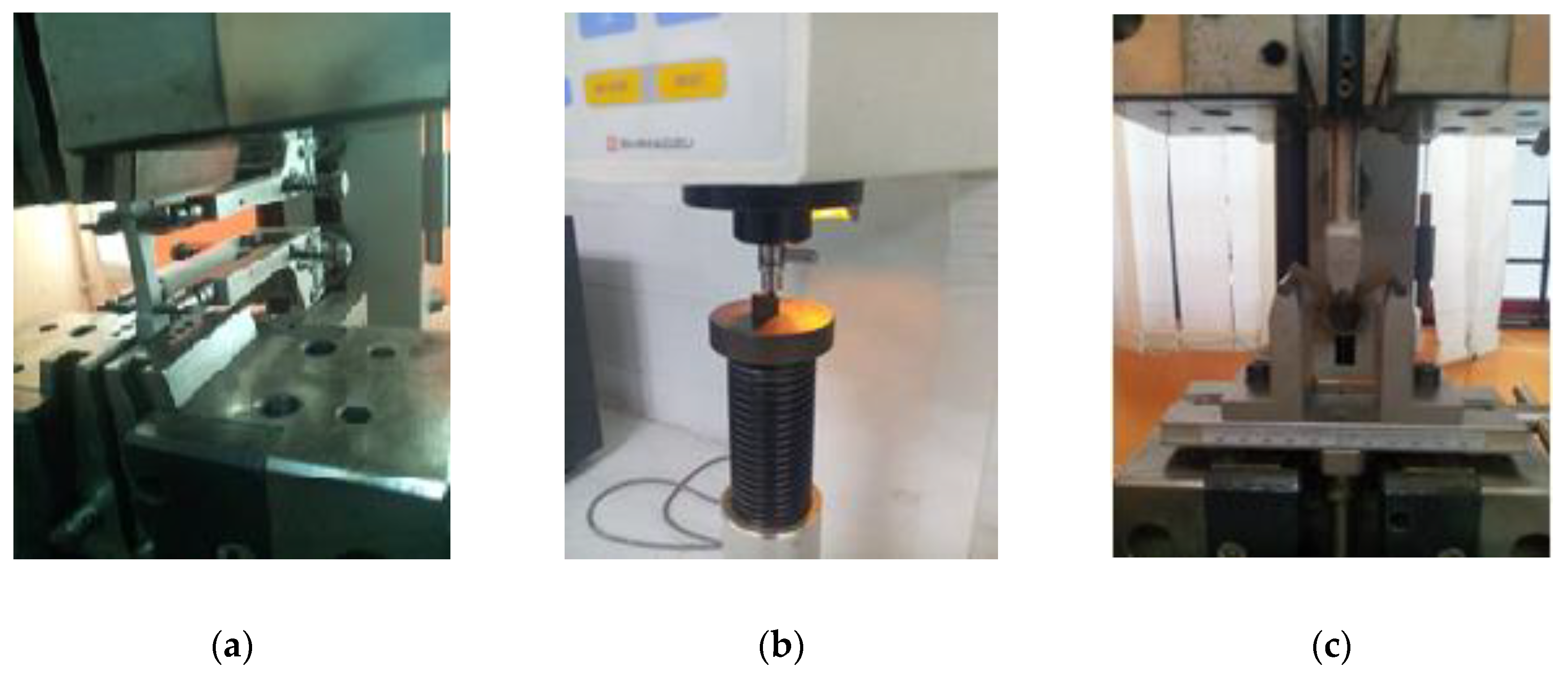
In this study, a series of mechanical tests such as tensile test, hardness test and three-point bending test was performed to determine the mechanical properties of material constituting the laminated panel, aluminium alloy Al7075-T6 and steel Ar500, and the original armour steel, Rolled Homogeneous Armour (RHA). The specimen used in the tensile test was prepared according to the size of 6 mm × 140 mm × 6 mm in compliance with the ASTM E8. The strain rate and the crosshead speed were set at 0.001 s−1 and 1.8 mm/min, respectively [12]. This test was carried out to determine the material properties such as Young’s modulus, yield strength and ultimate tensile strength. In measuring the hardness of the tested materials, Rockwell hardness tester was used for B scale hardness measurement. The Rockwell scale B is a hardness scale based on indentation hardness of a material. The specimen was prepared according to ASTM E18 with a size of 10 mm × 10 mm × 10 mm to test the materials resistance against penetration [13]. The three-point bending test was also performed to determine the mechanical properties of materials when subjected to the impact on the front of panel and to identify energy absorption capability of each material [8]. In this test, the specimen was cut to a size of 5 mm × 50 mm × 10 mm in accordance with ASTM E290 and was tested by the universal testing machine at a speed of 5 mm/min which is commonly used to test metal bending behaviour [14]. The machines used for all above tests are shown in Figure 2.

2.2. Experimental Ballistic Test

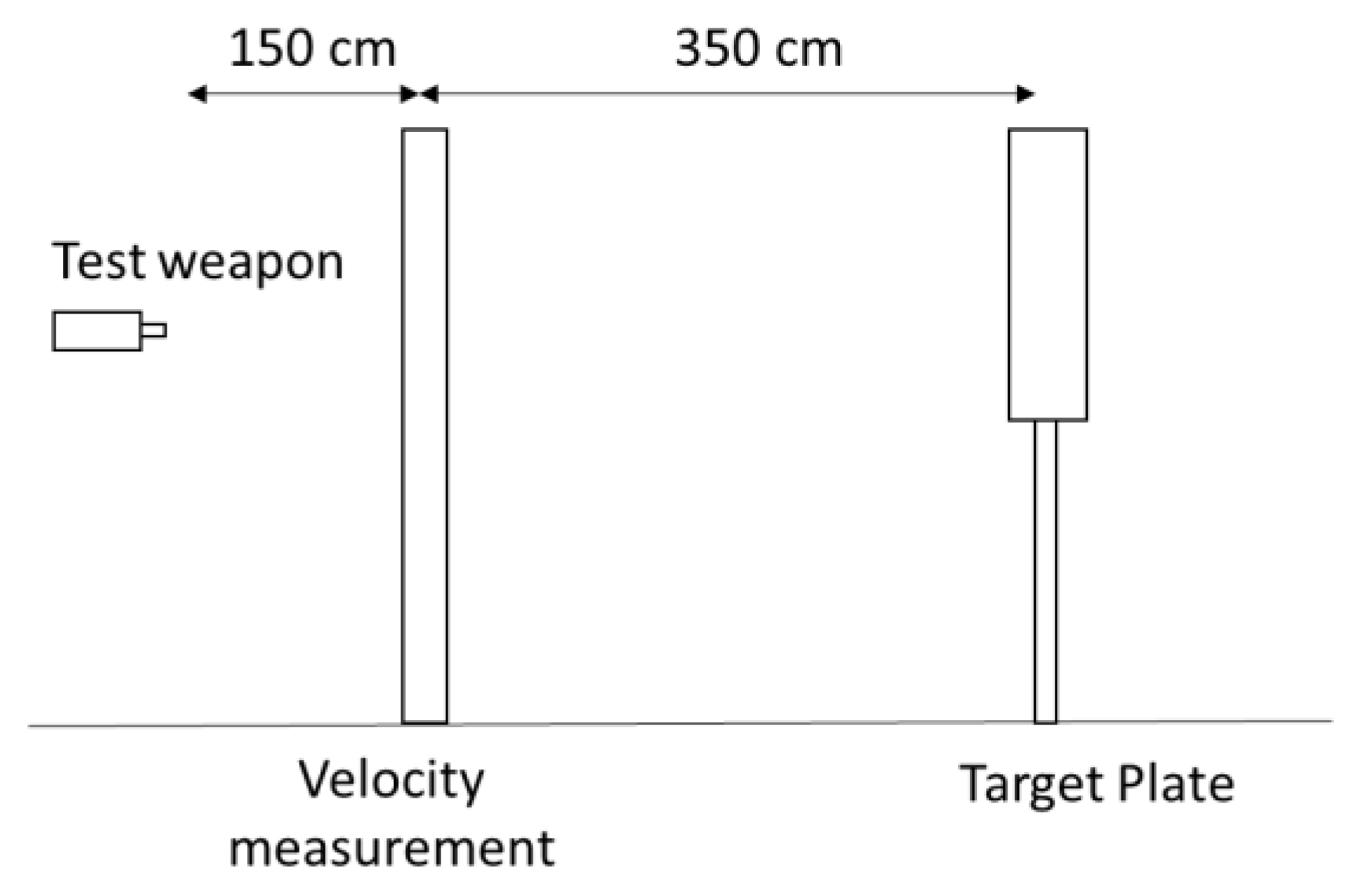
The dimensions of ballistic test plates of double-layered for both configurations were in 100 × 100 mm2 following the NATO Stanag 4569 standard. This dimension is adequate to ensure there is no force induced on the bullet from the reflected wave by the edge of plate during the impact. All layered plates were in direct contact with each other and plate spacing effect or adhesion effect on ballistic resistive performance were not considered in this study. The target plates were mounted on a stiff frame in the ballistic test set-up as in Figure 3 and subjected to three shoots each. The ballistic tests were performed using NATO Stanag 4569 standard level threat two threat. The ammunition for the level threat two is named as 7.62 mm full metal jacket (FMJ) which is composed of a copper jacket and a lead core. The velocity of the bullet was kept around 830 m/s as stated in Stanag 4569. The velocity measurement system and test were placed at 3.5 m away and 5.0 m away from the target.
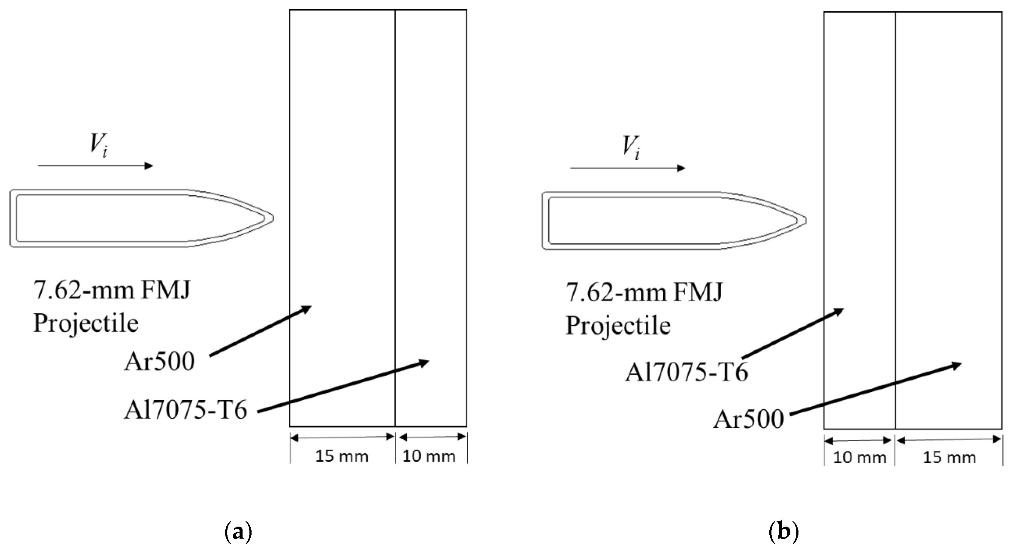
The ballistic tests were carried out to investigate the behaviour of two different configurations of double-layered panel which have same areal density and thickness of each constituting material subjected to high velocity impact. The geometric model of the layered plates is shown in Figure 4a,b. The first double layered panel designated as Configuration A (Figure 4a) consists of a 15-mm thick Ar500 as the front layer and a 10-mm thick Al7075-T6 as the back layer. Meanwhile, second double layered panel (Figure 4b) is presented as Configuration B consisting of a 10-mm thick Al7075-T6 as the front layer and a 15-mm thick Ar500 as the back layer. These panels were designed to be for armoured vehicle application to achieve the NATO Stanag 4569 ballistic application of level threat 2 [14].

2.3. Computational Ballistic Test

Computational ballistic test was performed using the explicit dynamic finite element method (FEM). In solving the problem modelled in FEM, there are four established methods that can be utilised: Eulerian method, Lagrangian method, arbitrary-Lagrangian–Eulerian (ALE) method and smooth-particle hydrodynamics (SPH) method. Eulerian method involves volume constraint to solve problem equations through the conservation of mass, momentum and energy. ALE method is extended from the Lagrangian method, in which some computation steps have been added to solve grid movement problem using simulation. It can give stability during computation distortion but lengthy computational time and space is needed. SPH method is an extension of Lagrangian method and suitable for complex behaviour during simulation. However, it is difficult to determine the boundary condition of this method as there is no geometry defined. Lagrangian on the other hand can solve complex problem with minimum requirement for computational time and space. The problem of element distortion arisen from this method can be solved by introducing the geometry erosion model during finite element modelling.
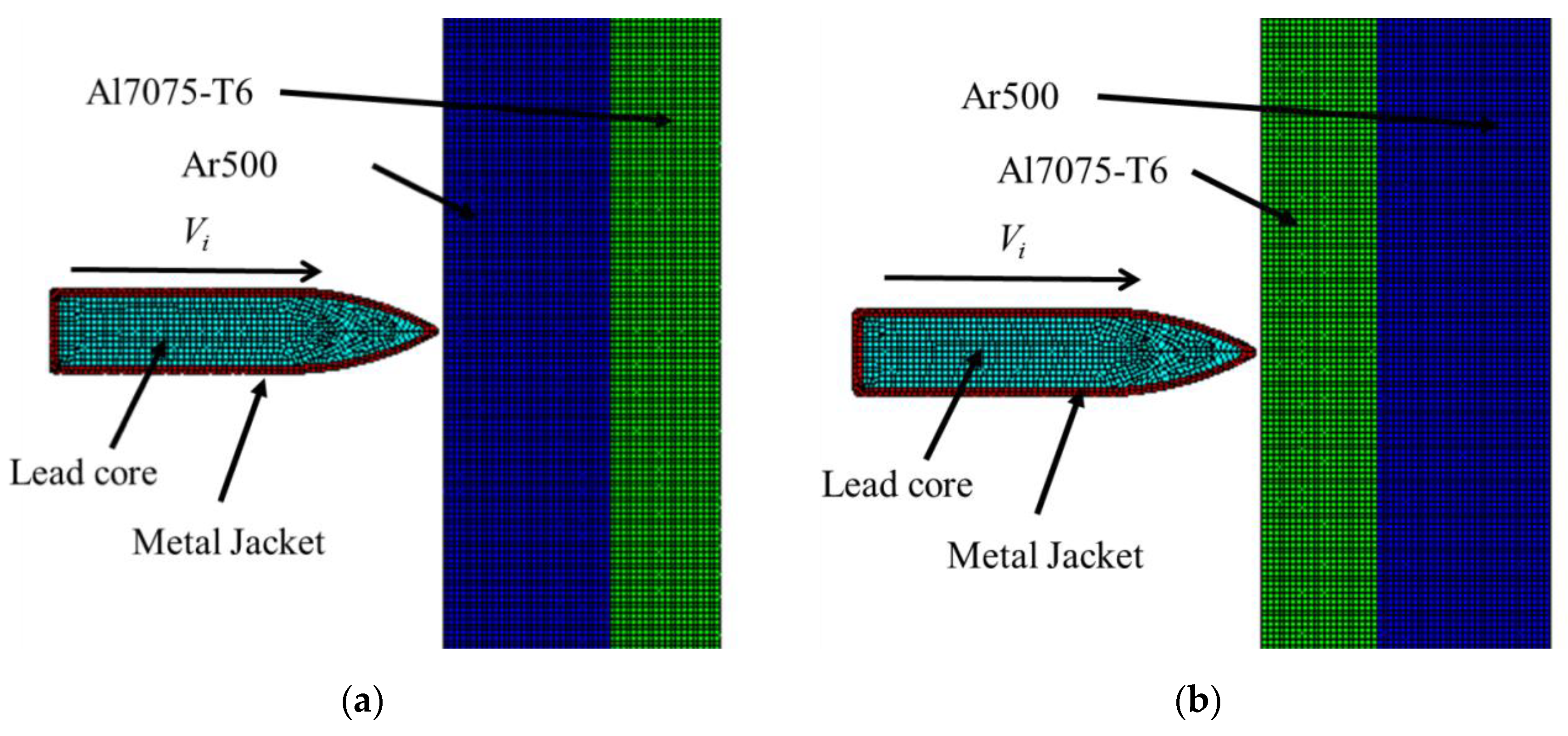
A specific commercial simulation software package was used to develop a two-dimensional model for ballistic tests. A 7.62 mm FMJ projectile was used at initial velocities ranging from 810 m/s to 850 m/s. Initial velocity was chosen according to NATO Stanag 4569 ballistic protection level 2 which is 830 ± 20 m/s, for both layout configurations. The target plate was modelled as 50 mm diameter circular plate and fully clamped at the edge boundaries as in Figure 5a,b. The projectile was modelled in two independent parts: metal jacket and lead core, which has outer diameter of 7.7 mm, inner diameter of 6.2 mm and length of 35 mm. The target plate was modelled as 50 mm diameter circular plate and fully clamped at the edge boundaries. The target plate for computational method was designed as circular plate which differs from that of experimental method, because the computational method requires asymmetrical model for the two-dimensional simulation modelling. This is important to save computational time and computer memory required for simulation. However, based on Forrestal et al. [9] and Flores-Johnson et al. [10], ballistic results for a 50-mm diameter circular plate and a 100-mm × 100-mm square plate did not vary because the deformation caused by high speed impact happens locally.
In finite element analysis, the problem was considered as axisymmetric model as the bullet rotation is not considered because, in this study, the main interest is the behaviour of impacted panel. A constant mesh size of 0.5 mm was selected to finely resolve each problem and make the through thickness elements for the penetration process to be 50 elements. This size was found to adequately produce good results based on previous work by Rahman et al. (2016) [15]. The plates were modelled using node-to-node connectivity using pure langrage algorithm with implementation of geometric erosion strain to avoid failure. The penetration mechanics at very high velocity does involve in temperature effects. Therefore, the Johnson–Cook material constitutive models were suitable to represent the target plate and projectile in the finite element analysis.
Besides, the contact condition used between plates and projectile was defined as trajectory contact. Node-to-node connectivity was applied using pure langrage algorithm with implementation of geometric erosion. This technique was able to remove the elements experiencing large distortion and, consequently, simulation failure can be avoided [10,15]. Developing glue or bonding model in finite element modelling is another issue occurred frequently in obtaining accurate result [16]. At this stage, no bonding material was included to avoid large error during analysis. Therefore, to imitate closely finite element model behaviour, the panels were simply clamped without any joining material in between during the experiment.
All panels have same total thickness of 25 mm. The important factor in the sample size is its thickness because the selected thickness of 25 mm is the standard thickness of existing armour panel [15]. Each layer thickness was set accordingly to the 25% weight reduction of original armour panel to ensure the body maintaining on the ground during extreme conditions such as blasting and explosion. Both projectile and target panels used the Johnson–cook (JC) constitutive material model which has been commonly used for high velocity impact simulation [9,17,18]. The JC model is applied to determine the strain rate and temperature dependence of viscous-plastic material models and is expressed as [18] in Equation (1)
σ e q = ( A + B ε e q n ) ( 1 + ε ˙ e q * ) C ( 1 T * m )
where σ e q is the equivalent stress; ε e q is the equivalent plastic strain; A , B , n , C and m are the material constants; and ε ˙ e q * = ε ˙ e q / ε ˙ 0 is the dimensionless strain rate where it is a ratio of the strain rate and a user-defined strain rate. T * m is the homologous temperature and is given by T * m = ( T T r ) ( T m T r ) , where T r and T m represent the room temperature and the melting temperature, respectively. This modified JC material model has been successfully implemented to model impact on steel [16] and aluminium targets [9]. The JC parameters used in this study are shown in Table 1. JC material constitutive models were utilised to avoid the stresses transmitted to the steel core were limited by the flow stress of the lead and brass jacket material during high velocity impact [19].
Failure is modelled using a criterion proposed by Johnson and Cook. It depends on the effect of stress triaxiality, temperature and strain rate. The model was defined as in Equation (2) assuming that the damage accumulates in the material element during plastic straining and it breaks immediately when damage reaches a critical value.
D = { 0 , w h e n   ε p ε p , d D c / ( ε f ε p , d ) ,   w h e n   ε > ε p , d
where Dc is the critical damage, ε p , d is the damage threshold and ε f is the fracture strain given by the Johnson–Cook, as presented in Equation (3), whereby D1D5 are the material constants given in Table 2. These parameters were adopted from previous research works that possess similar material properties.
ε f = [ D 1 + D 2 exp ( D 3 σ ) ] [ 1 + D 4 ln ε ˙ ] [ 1 + D 5 T ]

3. Results and Discussion

3.1. Determination of Material Properties

Tensile testing was performed three times for each material and the average value of the results obtained were taken as the reference for identifying the mechanical properties of the material. It can be observed from the condition of specimens resulted in Figure 6 that these three materials possess the elastic properties due to the necking process taken place before the material fracture. These materials have elastic to plastic deformation prior to failure and fracture at the same place that is 1/3 of the length gauge as a result of consistent pull off action to cause similar spot of stress concentration [20]. The results from experimental tensile tests are provided in Figure 7 where the ultimate strength of Ar500 and Al7075-T6 are 1687 MPa and 545 MPa, respectively. A slight difference in elongation of these materials where Ar500 exhibits 12.07% and Al7075-T6 is at 11.71%. The summary of mechanical properties of the high strength steel and aluminium alloy are tabulated in Table 3. Based on the stress–strain curve in Figure 6, steel Ar500 shows similar mechanical properties to RHA and is stronger than aluminium alloy Al7075-T6 due to the higher carbon content in the material.
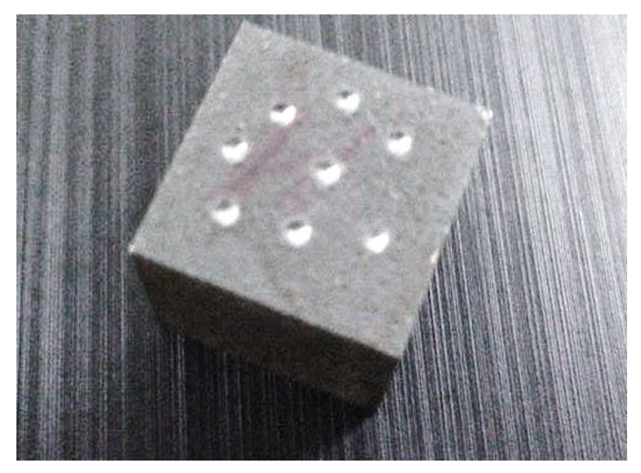
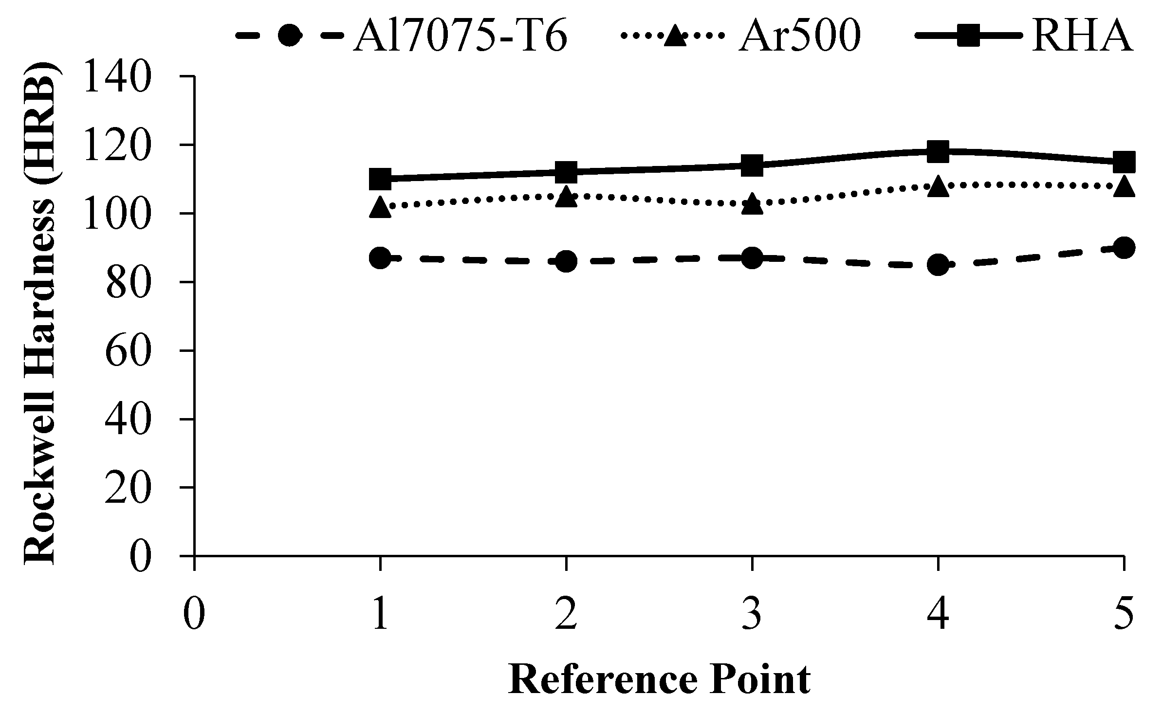
Rockwell hardness values obtained from the hardness test for Al7075-T6 alloy, Ar500 and RHA are 87, 105, and 114 HRB, respectively are summarised in Table 4. The RHA hardness value is higher than other materials because of its material composition, RHA containing Molybdenum. Molybdenum is a material often used in alloying materials for high strength characteristics. Figure 8 shows the condition of specimen after five punching points for hardness test and Figure 9 represent the Rockwell hardness value against each punching point. The strength or hardness of the material at any point depends on the material capability to resist the penetration of the projectile. Each point represents a different value for the material microstructure changes occurred during cutting process. Through this test, it can be observed that RHA has the best penetration resistance compared to Ar500 and Al7075-T6 and the hardness feature is important to prevent the projectile from penetrating the plate.
Characterisation test was also performed by comparing the material properties of materials studied with similar materials of Forrestal et al. (2010) and Flores-Johnson et al. (2011) to adopt JC properties from these research works to be used in this study. The yield strength and ultimate strength of Ar500 steel and Al7075-T6 obtained were compared with those of Weldox 400E steel and Al7075-T651, respectively. The similarities between these materials are quite high, between 94.6% and 95.8%. Thus, the JC properties of Weldox 400E and Al7075-T651 can be used to represent the materials used in this study.
Bending test was performed on each material, Al7075-T6 and Ar500, to study the effect of the maximum force exerted on the material before it stopped and the deformation of these materials when subjected to bending tests. Each material was deformed as in Figure 10 producing maximum bending stress, bending strain and bending modulus as tabulated in Table 5. Results show that Ar500 steel shows better bending performance than Al7075-T6 which can be observed from its lower deformation compared to Al7075-T6 alloy. The bending test was conducted to study the mechanical properties and the ability of each material constituting laminated panel when subjected to the impact from the front. Tensile testing is inadequate to represent the resistivity characteristics of a material to the impact effect because the tensile test was conducted on a uniaxial direction and at different direction of the normal impact direction. In addition, bending test results can provide indication of the appropriate material to be placed in the front part of the layered material. Material with high elastic modulus is not suitable to be placed on the front panel because it will cause damage to the back material structure and consequently it can be easily penetrated by projectiles [21].

3.2. Effect of Ballistic Impact on Different Layering Configuration

The final conditions of the double layered panels with Configuration A and Configuration B resulting from the ballistic test conducted are shown in Figure 11a,b and Figure 12a,b, respectively. Ballistic test results show that the projectile partially penetrated both panels with depth of penetrations between 1.3 and 1.7 mm for Configuration A, and between 10 and 11 mm for Configuration B. The average after three shoots was calculated as 1.5 mm and 10.3 mm for Configuration A and Configuration B, respectively. Double-layered panels with Configuration A and Configuration B possess similar areal density and weight. Only layering configuration differs and significantly affected the panel behaviour during the high velocity impact. At high velocity, maximum stress occurred at the early stage of penetration process because the panel had to withstand the high pressure and kinetic energy from this projectile and then it slowly degraded as the plate distributed the stress all over the panel [22]. Both configuration panels have caused the projectile to completely shatter. Deformation occurred on the projectile nose during penetration led to an immense heat generation and the material of the panel locally melts and loses all mechanical strength [23]. The Configuration A panel which has front panel with 20% higher hardness than the front panel of Configuration B successfully stopped the projectile from penetrating the panel at 1.3 mm depth. This phenomenon is related with energy absorption capability and the strength of the material. The Configuration B panel allowed projectile penetrating the front layer panel and then successfully stopped the penetration at the back layer.
The results from simulation were compared with ballistic test results in terms of depth of penetration and crater diameter tabulated in Table 6. The percentage differences of the depth of penetration and crater diameter range between 10.7% and 20%, and between 9% and 20%, respectively. Although the differences seem to be high in term of percentage for Configuration A, the differences in term of real value were quite small: 0.3 mm for depth of penetration and 2 mm for crater diameter. The cause of this big mismatch is due to lack of symmetry of the crater diameter. The fracture caused in the front layer is due to reflected tensile wave which is called spallation and usually is circular shape [24]. The projectile during the ballistic test is not in normal direction to the target panel and is usually subjected to a degree of obliquity. Thus, it has affected the penetration process by which the obliquity reduces the depth of penetration but increases the crater diameter.
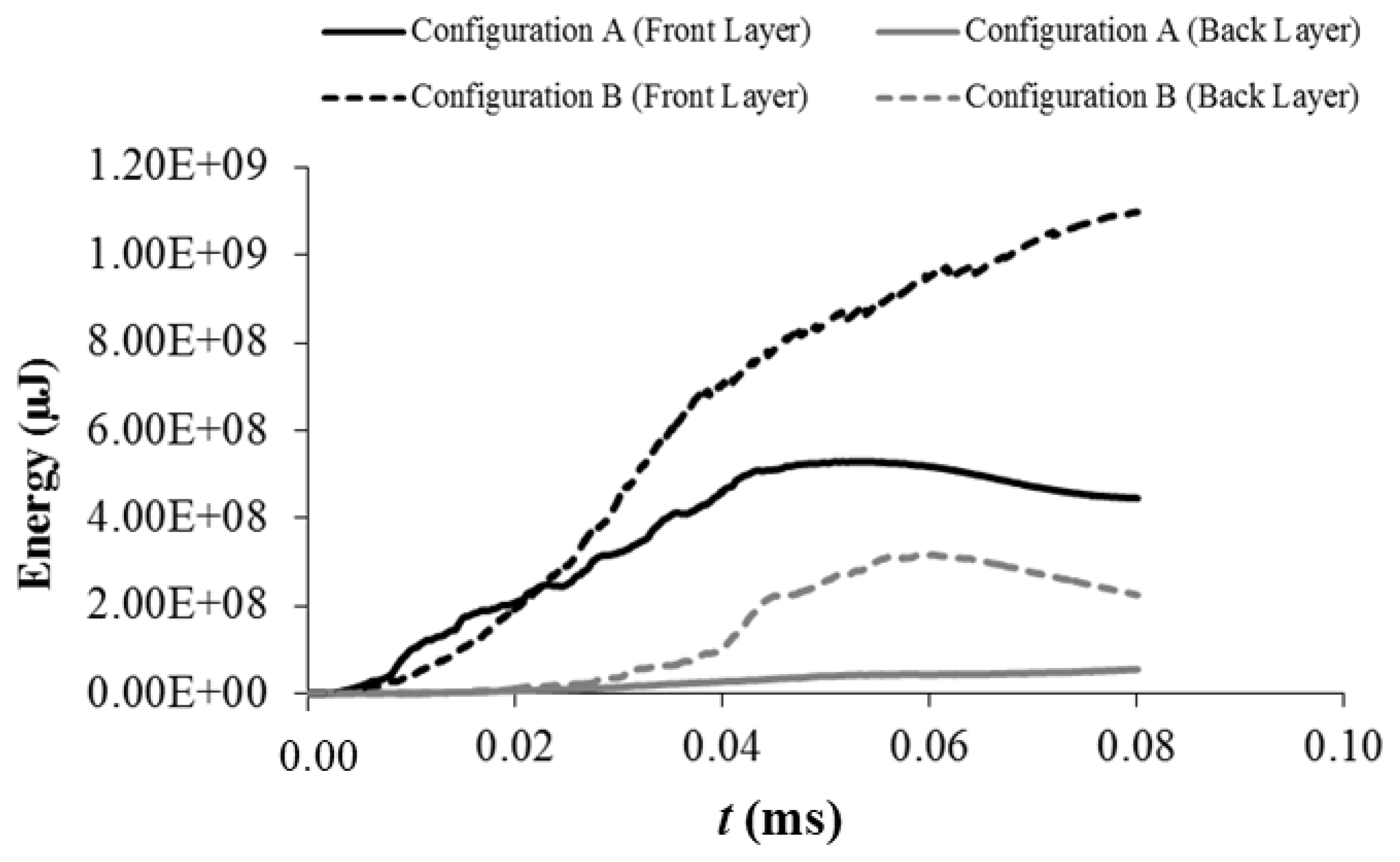
Simulation results in Figure 13a,b show that the 7.62-mm FMJ projectile was deformed and shattered completely when striking each configuration panel at a velocity of 800 m/s. However, penetration process taking place differed by which it completely penetrated front layer of Al7075-T6 in Configuration B panel and failed to penetrate through the front layer of Ar500 in Configuration A panel. Nevertheless, the projectile has also stopped at the back layer of Ar500 in Configuration B which is caused by the high tensile strength and high hardness properties of Ar500 material. Time taken by the Configuration A panel to stop the projectile was 16.7% shorter than time taken by the Configuration B panel (Figure 14). Both panels caused the projectile to shatter after the impact and the projectiles debris moved from the panel at opposite of initial direction, as shown in Figure 14, after 0.05 ms and 0.06 ms for Configurations A and B, respectively. The duration time of penetration process is associated with the amount of energy being absorbed during the impact occurred. Figure 15 shows the energy being absorbed by the front and back layer for each configuration panel at projectile initial velocity of 800 m/s. A large amount of energy, about 1400 J, was absorbed by the Configuration B panel due to the perforation process that occurred on the front layer. Meanwhile, Configuration A panel absorbed 58.6% less energy, about 580 J, to stop the projectile.
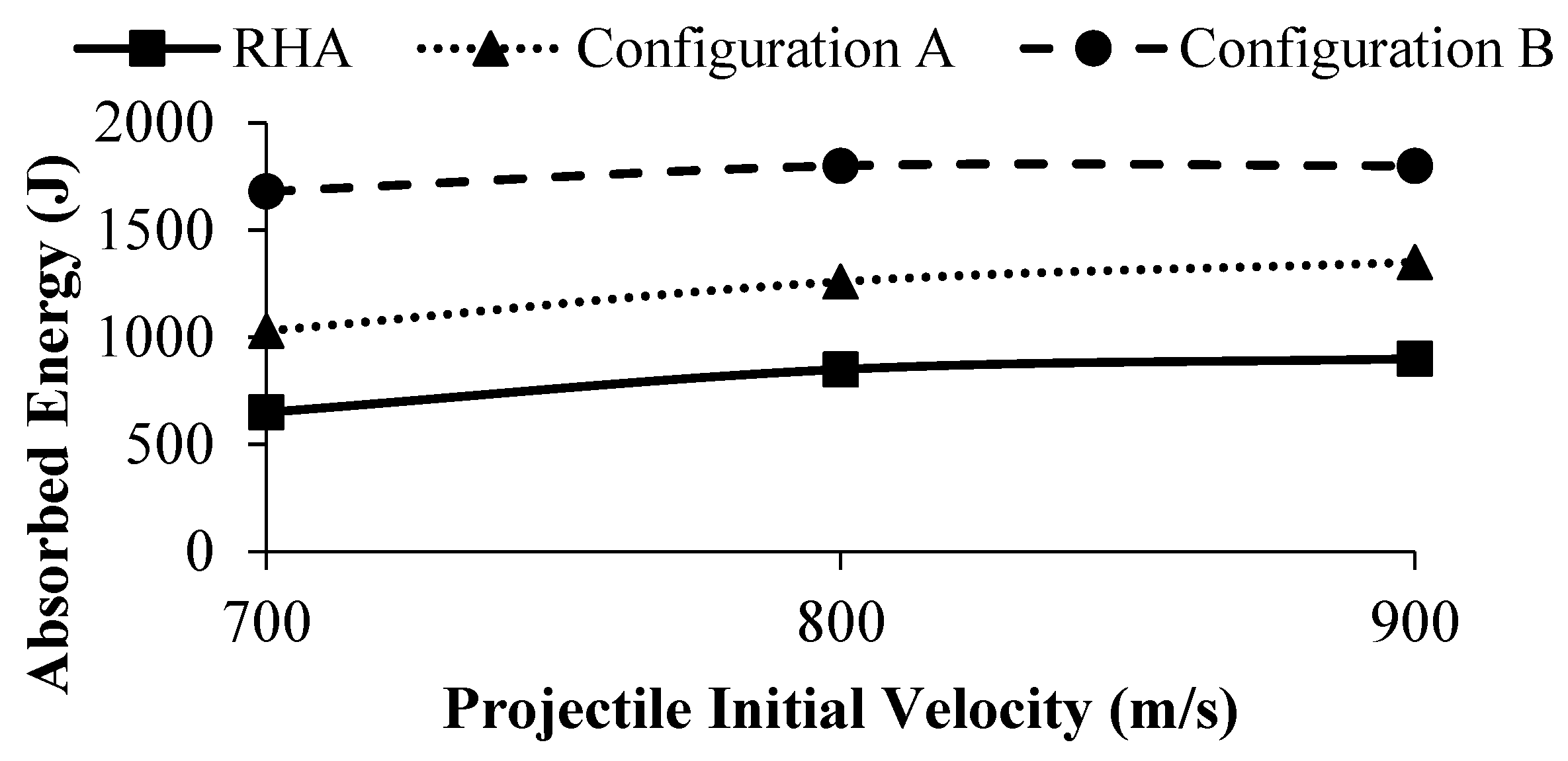
Numerical studies of the ballistic impact with penetration show that the absorption capabilities are increased at higher impact velocities, and energy absorption has its limit at higher velocities regardless of which laminated panel is used as the target. These phenomena are related to an elastic response of the panel because of essential role played by the deformation of the laminated panel. Figure 16 shows that double-layered panel with Configuration A exhibits lesser energy absorption than Configuration B panel, and RHA panel absorbed the least energy compared to double-layered panels with Configuration A or B. This happens due to the effectiveness of ballistic resistance properties of monolithic panel which is higher than that of multi-layered panels [25]. These double-layered panels which have similar areal density with only different layering configuration however performed differently. High strength steel when placed at the front layer as in Configuration A prevented any penetration happening to the layered panel because of the ability of the front layer to absorb most of the kinetic energy from the projectile. Besides, material hardness also plays an important role in increasing the ballistic resistance. Configuration A panel has shattered the projectile completely with 6% less and 24% more energy needed to be absorbed by the panel compared to Configuration B panel and existing RHA panel, respectively.
Figure 17 and Figure 18 illustrate the stress distribution pattern for each panel at time from 10 µs to 70 µs for an initial velocity of 800 m/s. The concentration of stress for each time observed was around the tip of projectile. The projectile retained its shape when penetrating the plate and the tip of the projectile was progressively deformed at the same time as the material in the panel was displaced and a hole was formed. Large amount of energy absorbed in front panel of Configuration A associated with large stress was distributed on the front panel. This front panel is can withstand the projectile penetration. A different phenomenon occurred on the front panel of Configuration B. The front panel made of aluminium failed to absorb and distribute the stress throughout its volume, as shown in Figure 18. The back layer played the role of withstanding the projectile penetration, and stopped the projectile at its surface.

4. Conclusions

Numerical and experimental results show that lightweight material Al7075-T6 alloy when placed at back layer of double-layered panel has a better ballistic performance than when it is placed at the front layer for a similar areal density panel. The difference in terms of the depth of penetration is quite significant (600%), while in terms of energy absorption, the difference is marginal (6%). However, the performance of the double-layered panel is 20% less than that of existing RHA panel. Considering the 25% weight reduction achieved, the armour shield made of these two materials with Configuration A, whereby Ar500 steel and Al7075-T6 alloy are placed at front and back layer, respectively, could potentially perform better than the equivalent areal density monolithic steel plate. However, the results in this study are limited and further research has to be carried out to fully understand this type of target configuration. It is concluded that layering configuration does matter in improving the ballistic performance of laminated panel consisting different types of materials. This study could be further performed to investigate the behaviour of stress distribution on the plates during the projectile impact and penetration.

Author Contributions

N.A.R. carried out the experimental and computational works, analysis and writing under the supervision of S.A., M.Z.O., Z.S. and W.F.H.Z., while M.F.A. provides guidance on the experimental works and the write-up.

Funding

This research was funded by Ministry of Higher Education Malaysia [LRGS/2013/UPNM-UKM/DS/04].

Acknowledgments

The authors wish to express their gratitude to the Ministry of Higher Education Malaysia, Universiti Kebangsaan Malaysia and Universiti Pertahanan Nasional Malaysia for the financial assistance and support.

Conflicts of Interest

The authors declare no conflict of interest.

References

  1. Jena, P.K.; Ramanjeneyulu, K.; Siva Kumar, K.; Balakrishna, B.T. Ballistic studies on layered structures. Mater. Des. 2009, 30, 1922–1929. [Google Scholar] [CrossRef]
  2. Teng, X.; Dey, S.; Børvik, T.; Wierzbicki, T. Protection performance of double-layered shields against projectile impact. J. Mech. Mater. Struct. 2007, 2, 1309–1329. [Google Scholar] [CrossRef]
  3. Volgas, D.A.; Stannard, J.P.; Alonso, J.E. Ballistics: A primer for the surgeon. Injury 2005, 36, 373–379. [Google Scholar] [CrossRef] [PubMed]
  4. Jena, P.K.; Mishra, B.; Siva, K.K.; Bhat, T.B. An experimental study on the ballistic impact behavior of some metallic armour materials against 7.62 mm deformable projectile. Mater. Des. 2010, 31, 3308–3316. [Google Scholar] [CrossRef]
  5. Liu, W.; Chen, Z.; Chen, Z.; Cheng, X.; Wang, Y.; Chen, X.; Liu, J. Influence of different back laminate layers on ballistic performance of ceramic composite armor. Mater. Des. 2015, 87, 421–427. [Google Scholar] [CrossRef]
  6. Børvik, T.; Forrestal, M.J.; Hopperstad, O.S.; Warren, T.L.; Langseth, M. Perforation of AA5083-H116 aluminium plates with conical-nose steel projectiles—Calculations. Int. J. Impact Eng. 2009, 36, 426–437. [Google Scholar] [CrossRef]
  7. Wei, Z.; Yunfei, D.; Sheng, C.Z.; Gang, W. Experimental investigation on the ballistic performance of monolithic and layered metal plates subjected to impact by blunt rigid projectiles. Int. J. Impact Eng. 2012, 49, 115–129. [Google Scholar] [CrossRef]
  8. Gupta, N. On microstructure and flexural strength of metal-ceramic composite cladding developed through microwave heating. Appl. Surf. Sci. 2012, 258, 5583–5592. [Google Scholar]
  9. Forrestal, M.J.; Børvik, T.; Warren, T.L. Perforation of 7075-T651 Aluminum armor plates with 7.62 mm APM2 bullets. Exp. Mech. 2010, 50, 1245–1251. [Google Scholar] [CrossRef]
  10. Flores-Johnson, E.A.; Saleh, M.; Edwards, L. Ballistic performance of multi-layered metallic plates impacted by a 7.62-mm APM2 projectile. Int. J. Impact Eng. 2011, 38, 1022–1032. [Google Scholar] [CrossRef] [Green Version]
  11. Übeyli, M.; Balci, E.; Sarikan, B.; Sarikan, B.; Öztaş, M.K.; Camuşcu, N.; Yildirim, R.O.; Keleş, Ö. The ballistic performance of SiC-AA7075 functionally graded composite produced by powder metallurgy. Mater. Des. 2014, 56, 31–36. [Google Scholar] [CrossRef]
  12. Mansourinejad, M. Influence of sequence of cold working and aging treatment on mechanical behaviour of 6061 aluminum alloy. Trans. Nonferrous Met. Soc. China 2012, 22, 2072–2079. [Google Scholar] [CrossRef]
  13. Hryha, E.; Zubko, P.; Dudrová, E.; Pešek, L.; Bengtsson, S. An application of universal hardness test to metal powder particles. J. Mater. Process. Technol. 2009, 209, 2377–2385. [Google Scholar] [CrossRef]
  14. Omar, M.Y.; Xiang, C.; Gupta, N.; Strbik, O.M.; Cho, K. Data characterizing flexural properties of Al/Al2O3 syntactic foam core metal matrix sandwich. Data Brief 2015, 5, 564–571. [Google Scholar] [CrossRef] [PubMed]
  15. Rahman, N.A.; Abdullah, S.; Zamri, W.F.H.; Abdullah, M.F.; Omar, M.Z.; Sajuri, Z. Ballistic limit of high-strength steel and Al7075-T6 multi-layered plates under 7.62-mm Armour Piercing Impact. Lat. Am. J. Solids Struct. 2016, 13, 1658–1676. [Google Scholar] [CrossRef]
  16. Børvik, T.; Dey, S.; Clausen, A.H. Perforation resistance of five different high strength steel plates subjected to small-arms projectiles. Int. J. Impact Eng. 2009, 36, 948–964. [Google Scholar] [CrossRef]
  17. Abdulhamid, H.; Kolopp, A.; Bouvet, C.; Rivallant, S. Experimental and numerical study of AA5086-H111 aluminum plates subjected to impact. Int. J. Impact Eng. 2013, 51, 1–12. [Google Scholar] [CrossRef] [Green Version]
  18. Børvik, T.; Langseth, M.; Hopperstad, O.S.; Malo, K. A perforation of 12mm thick steel plates by 20 mm diameter projectiles with flat, hemispherical and conical noses-Part I: Experimental study. Int. J. Impact Eng. 2001, 27, 19–35. [Google Scholar] [CrossRef]
  19. Wang, C.; Suo, T.; Li, Y.; Xue, P.; Tang, Z. A new experimental and numerical framework for determining of revised J-C failure parameters. Metals 2018, 8, 396. [Google Scholar] [CrossRef]
  20. Kumar, S.M.; Pramod, R.; Kumar, M.E.S.; Govindaraju, H.K. Evaluation of fracture toughness and mechanical properties of Aluminum alloy 7075-T6 with nickel coating. Procedia Eng. 2014, 97, 178–185. [Google Scholar] [CrossRef]
  21. Deng, Y.; Zhang, W.; Cao, Z. Experimental investigation on the ballistic resistance of monolithic and multi-layered plates against hemispherical-nosed projectiles impact. Mater. Des. 2012, 41, 266–281. [Google Scholar] [CrossRef]
  22. Wang, Y.; Wang, F.C.; Yu, X.D.; Ma, Z.; Gao, J.B.; Kang, X.P. Effect of interlayer stress wave propagation in CMC/RHA multi-layered structure. Compos. Sci. Technol. 2010, 70, 1669–1673. [Google Scholar] [CrossRef]
  23. Kiliç, N.; Ekici, B. Ballistic resistance of high hardness armor steels against 7.62 mm armor piercing ammunition. Mater. Des. 2013, 44, 35–48. [Google Scholar] [CrossRef]
  24. Übeyli, M.; Yildirim, O.R.; Ögel, B. On the comparison of the ballistic performance of steel and laminated composite armors. Mater. Des. 2007, 28, 1257–1262. [Google Scholar] [CrossRef]
  25. Gupta, N.K.; Iqbal, M.A.; Sekhon, G.S. Effect of projectile nose shape, impact velocity and target thickness on the deformation behavior of layered plates. Int. J. Impact Eng. 2008, 35, 37–60. [Google Scholar] [CrossRef]
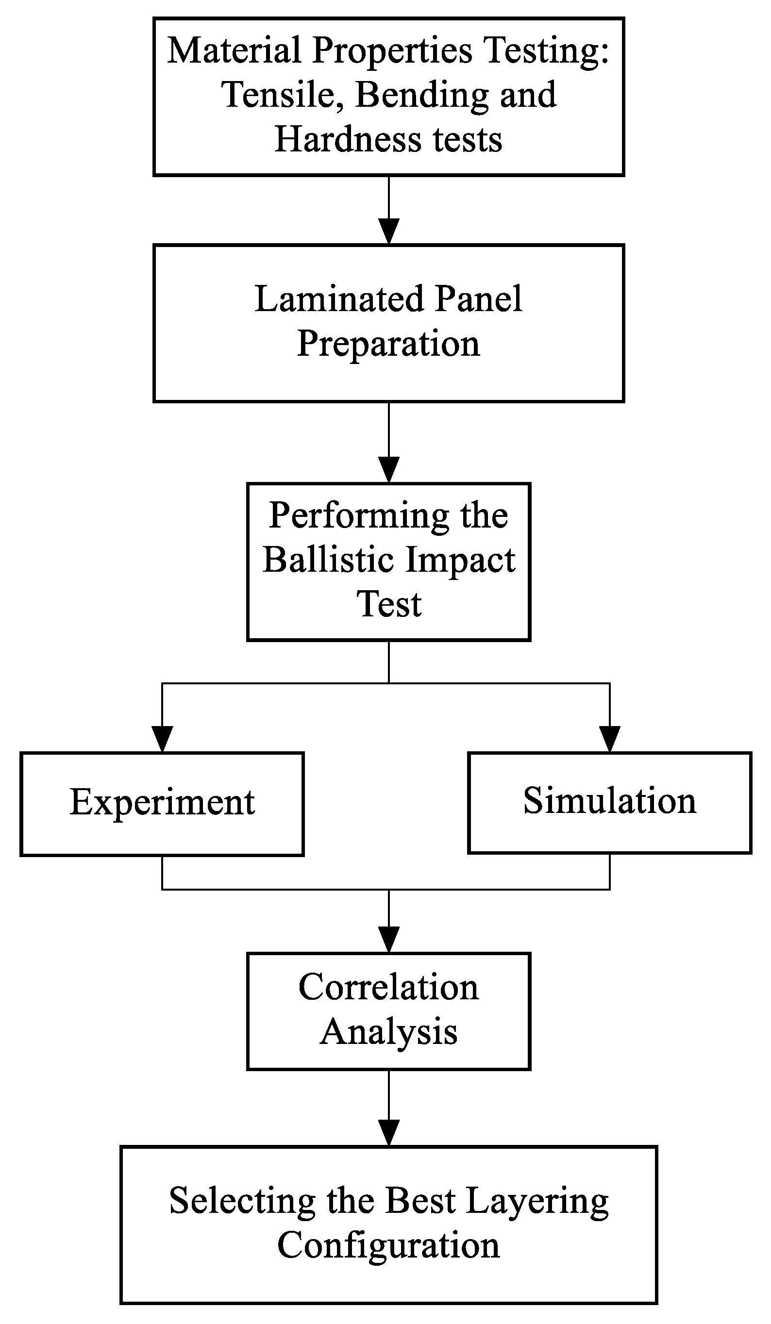
Figure 1. Flow diagram of a methodology used for this work.
Metals 08 00732 g001
Figure 2. Machines for mechanical test performed for: (a) tensile test; (b) hardness test; and (c) three-point bending test.
Metals 08 00732 g002
Figure 3. The schematic of the ballistic test system used.
Metals 08 00732 g003
Figure 4. The cross-section geometrical model of the 7.62-mm FMJ projectile double-layered panel for: (a) Configuration A; and (b) Configuration B.
Metals 08 00732 g004
Figure 5. FEA model of 7.62-mm FMJ projectile and double-layered target plate for: (a) Configuration A; and (b) Configuration B.
Metals 08 00732 g005
Figure 6. After tensile test fracture condition for: (a) RHA; (b) Ar500; and (c) Al7075-T6.
Metals 08 00732 g006
Figure 7. Stress–strain curves for RHA, Ar500 and Al7075-T6 at 1.5 mm/min.
Metals 08 00732 g007
Figure 8. After hardness test condition with different punching points.
Metals 08 00732 g008
Figure 9. Rockwell hardness value at different punching point for each material.
Metals 08 00732 g009
Figure 10. After three-point bending test condition for: (a) Ar500 steel; and (b) Al7075-T6 alloy.
Metals 08 00732 g010
Figure 11. Final condition of plates constituting Configuration A panel: (a) front layer of Ar500 steel; and (b) back layer of Al7075-T6 alloy.
Metals 08 00732 g011
Figure 12. Final condition of plates constituting Configuration B panel: (a) front layer of Al7075-T6 alloy; and (b) back layer of Ar500 steel.
Metals 08 00732 g012
Figure 13. Penetration of FMJ projectile at 0.07 ms and initial velocity of 800 m/s for: (a) Configuration A; and (b) Configuration B.
Metals 08 00732 g013
Figure 14. Projectile velocity as a function of time for each plate at initial velocity of 800 m/s.
Metals 08 00732 g014
Figure 15. Energy absorbed by front and back layers of each plate at initial velocity of 800 m/s.
Metals 08 00732 g015
Figure 16. Total energy absorbed by the laminated panel at different initial projectile velocity.
Metals 08 00732 g016
Figure 17. Stress distribution patterns of Configuration A panel at time between 10 μs and 70 μs at initial projectile velocity of 800 m/s.
Metals 08 00732 g017
Figure 18. Stress distribution patterns of Configuration B panel at time between 10 μs and 70 μs at initial projectile velocity of 800 m/s.
Metals 08 00732 g018
Table 1. Material properties and modified Johnson–Cook model parameters, adopted from [9,16] with permission from Springer Nature, 2010 and Elservier, 2009.
Material PropertiesRHAAr500Al7075-T6Copper JacketLead Core
Density, ρ (kg/m3)780078602804852010600
Young’s Modulus E (GPa)7.6907.692.693.70.56
Poisson’s ratio, ν0.330.330.30.310.42
Yield Strength, A (MPa)780125048020624
Strain Hardening, B (MPa)78036252020624
Strain Hardening exponent, n 0.10610.520.421
Strain rate constant, c 0.0040.01080.0010.010.1
Thermal softening constant, m11111
Melting temperature, Tm (K)180018008931189760
Table 2. Johnson–Cook fracture model constants for target materials.
Damage ConstantAr500 [18]Al7075-T6 [9]
D10.05−0.068
D20.80.451
D3−0.44−0.952
D4−0.0460.036
D5−2.90.697
Table 3. The mechanical properties of RHA, Ar500 and Al7075-T6.
MaterialModulus Elasticity (GPa)Yield Strength, σy
(MPa)
Ultimate Tensile Strength, σuts
(MPa)
Stress at Break, σf
(MPa)
Elongation at Break
(%)
RHA21312301737125712.70
Ar50015014101687129312.07
Al7075-T67047254551611.71
Weldox 400E [9]14512501680120012.00
Al7075-T651 [16]7047748550011.00
Table 4. Summary of average hardness for each material.
MaterialRockwell Hardness Value (HRB)
RHA114
Ar500105
Al7075-T687
Table 5. Summary of three-point bending test results for each material.
MaterialMaximum Bending Stress, σB
(MPa)
Bending Strain,
εB
Bending Modulus, EB
(MPa)
Ar50018180.0754
Al7075-T66240.134
Table 6. Comparison between ballistic test and simulation results for depth of penetration and crater diameter.
PlateBallistic TestSimulationPercentage Difference
Depth of Penetration (mm)Crater Diameter (mm)Depth of Penetration (mm)Crater Diameter (mm)Depth of Penetration (%)Crater Diameter (%)
Configuration A1.5101.8122020
Configuration B10.31111.41210.79