Effect of the Parameters of Semi-Solid Processing on the Elimination of Sharp-Edged Primary Chromium Carbides from Tool Steel


1
Faculty of Mechanical Engineering, University of West Bohemia, RTI—Regional Technological Institute, Univerzitní 22, CZ-306 14 Pilsen, Czech Republic
2
COMTES FHT a.s., Průmyslová 995, CZ-334 41 Dobřany, Czech Republic
*
Author to whom correspondence should be addressed.
Metals 2018, 8(9), 713; https://doi.org/10.3390/met8090713
Submission received: 26 July 2018
/
Revised: 6 September 2018
/
Accepted: 7 September 2018
/
Published: 12 September 2018
(This article belongs to the Special Issue Tool Steels)
Abstract
:Although conventional tool steels have been heat treated on a routine basis for decades, the search continues for new ways to eliminate their troublesome sharp-edged primary chromium carbides, which impair toughness. One of the available techniques is semi-solid processing, which involves partial melting of the workpiece. The structure after semi-solid processing consisted of a austenite and carbide-austenite network. The network can be broken up and its fragments distributed uniformly by subsequent forming with appropriate parameters. In this experimental study, X210Cr12 tool steel was heated to a semi-solid state, and after cooling to a solid state, worked in a hydraulic press. Suitable soaking temperatures were sought within an interval between 1200 °C and 1280 °C. The workpieces were quenched from the forming temperature in water or oil. In order to improve formability and reduce hardness, tempering was tested as well. Additional experimental regimes included conventional quenching and tempering. Once the appropriate parameters were chosen, the elimination of primary chromium carbides was successful. The resultant microstructures were fine and consisted of M-A constituent with a size of approximately 1 μm, and very fine Fe3C and Cr7C3 carbides. The hardness was in excess of 800 HV10. They were examined using optical and scanning electron microscopes. The carbides were characterized on transparent foils in a transmission electron microscope. Mechanical characteristics were determined in micro-tensile tests.
1. Introduction
The properties of tool steels are governed by the amount, size, distribution, and shape of carbides [1,2,3]. Being hard particles, carbides have an effect on mechanical properties, wear, corrosion and creep resistance [2]. Depending on their size and morphology, they often play an important role in the initiation of failure under load [3]. Sharp-edged chromium carbides in particular reduce the toughness of the material. Primary carbides M7C3, which are typical of hypereutectoid steels, are produced by eutectic reaction during cooling [4]. They form directly from the melt and are difficult to eliminate by conventional process routes. For this reason, semi-solid processing appears to be an appropriate method for eliminating these carbides and producing fine-grained structures with fine carbide precipitates.
Semi-solid processing (SSP) entails partial melting. The presence of a liquid phase causes the material to exhibit a thixotropic behavior. Complex-shaped parts can thus be made using a single forming operation. Difficult-to-form materials can be shaped with low forming forces [5,6,7,8,9]. Semi-solid processing of materials with high solidus temperature, such as steels, is complicated by the high temperatures involved, by severe thermal loads on dies, and by a susceptibility to high-temperature oxidation [10]. Their resultant microstructures only after semi-solid processing consist of polyhedral austenite grains embedded in a ledeburite network [11,12]. The grain size and the morphology of the ledeburite network can be controlled by cooling [13]. Some studies dealt with behavior of the semi-solid structure after heat treatment and describe the stages of the austenite decomposition [11,13]. It is known that the austenite is stable up to annealing at 500 °C. At this temperature the formation of fine pearlite was observed [7,11]. Also, the influence of deformation in the semi-solid state was investigated [11]. The austenite remained stable even after 100% deformation in the semi-solid state [11]. The research also described the behavior of the semi-solid structure during cold deformation [14,15]. It was found that during compression test, cracks are formed within the eutectic network and the structure shows frequent twin bands within austenitic grains, deformation twins and ε-martensite [14]. But the possibility to extremely refine the grain size, as well as very fine carbides precipitates during cooling, still remains unanswered. One of the possibility is the intensive forming in different axes after cooling back from semi-solid to solid area.
This paper describes a combination of passage through semi-solid state with subsequent forming on a hydraulic press, which could lead to interesting structures. These structures may exhibit higher toughness due to the removal of sharp-edged primary carbides and good wear resistance. Thanks to the high soaking temperature the sharp-edged chromium carbides are dissolved and the ledeburite network resulting from the presence of liquid fraction is broken up and dispersed in the dynamically recrystallized matrix. To obtain the required structures, it is necessary to describe the influence of the individual processing parameters. The most important parameters are soaking temperature, cooling rate, and subsequent heat treatment.
2. Experimental Programme
The microstructure produced by semi-solid processing greatly depends on the soaking temperature, which dictates how primary chromium carbides dissolve and what the liquid fraction will be. Both liquid fraction and cooling rate strongly influence the process by which ledeburite network forms. However, the network can be eliminated by mechanical working during cooling. The deformation breaks up the network, disperses the fragments, and refines austenite grains thanks to recrystallization. For this reason, the effects on microstructural evolution need to be identified with respect not only to the soaking conditions but also to cooling from the forming temperature to room temperature. To make the experimental programme comprehensive, conventional treatment comprising quenching and tempering was included. The purpose of this experimental programme was to produce a fine-grained microstructure with fine secondary carbide precipitates, free of primary chromium carbides, in X210Cr12 tool steel.
2.1. Experimental Material
X210Cr12 steel is a typical representative of materials with sharp-edged chromium carbides. It is a hypereutectoid chromium steel with high hardenability (Table 1). It has a very high compressive strength and offers good cutting performance and wear resistance. It was developed for use in punching machines and presses, mainly for heavy-duty punches and highly-complex progressive and combination tools [16,17]. Products from this steel include general-purpose forming tools as well as extrusion tools and tools for cold shearing. In addition, it serves as a material for durable small dies for shaping plastic and powder materials, glass, porcelain, and ceramics. It is produced by a conventional metallurgical process which causes carbide banding and therefore poor toughness.
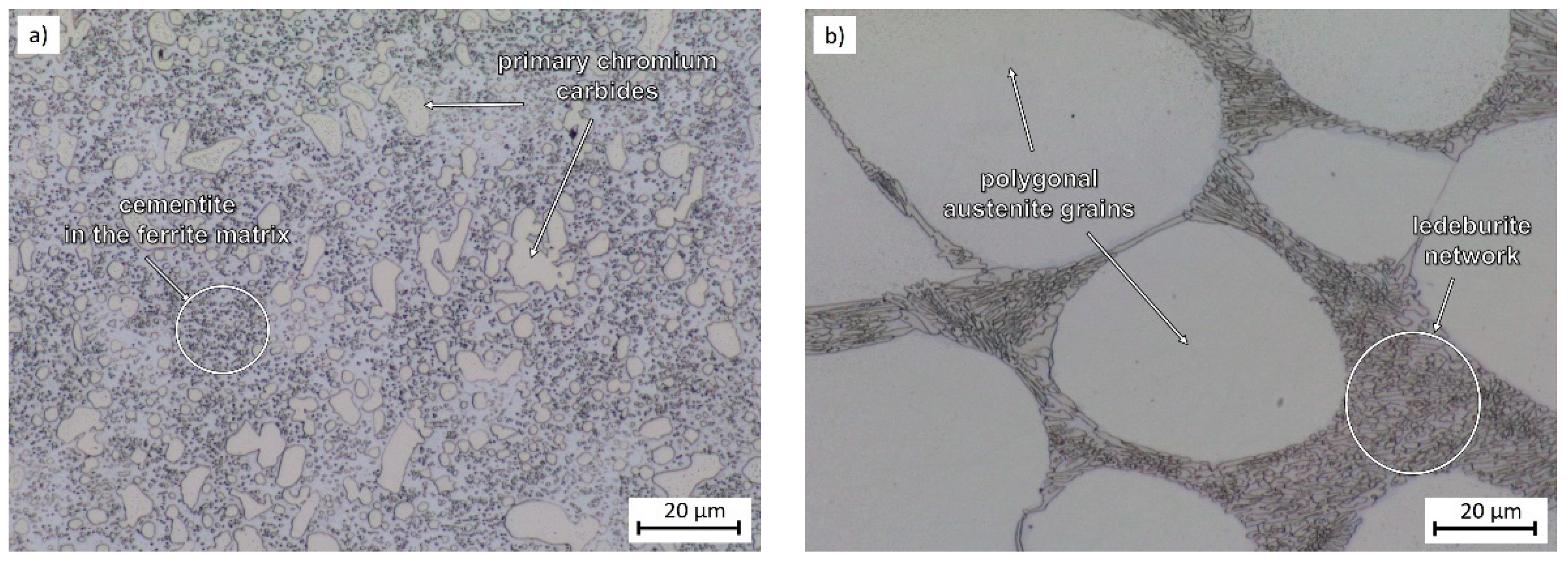
The material was supplied in the form of annealed bars. The as-received microstructure consisted of large sharp-edged primary chromium carbides and very fine cementite embedded in a ferritic matrix (Figure 1a). The hardness was 220 HV10. Using X-ray diffraction analysis, 24% cementite and 6% Cr7C3 carbides by volume were found in the as-received microstructure. Previous investigations into semi-solid processing of steels showed that sharp-edged chromium carbides can be dissolved into an austenitic matrix and then reprecipitated as a carbide network [7,12]. After semi-solid processing, the microstructure consists of polyhedral austenite grains embedded in a lamellar ledeburite network (Figure 1b). The amount of austenite was determined as 96%. Since the presence of such networks is undesirable as concerns toughness, they need to be eliminated by mechanical working during cooling.
2.2. Determination of Semi-Solid Processing Parameters
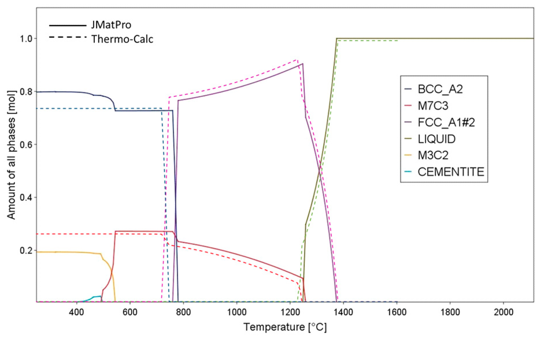
The key to designing an entire process route is determining the relevant phase transformation temperatures. In this case, they were calculated using JMatPro software [18], using Thermo-Calc software [19] (both using Thermotech databases), and determined by DSC analysis (Differential Scanning Calorimetry) (Table 2). According to the calculation with JMatPro, melting begins at 1225 °C and 100% of liquid fraction is obtained at 1373 °C (Figure 2). A liquid fraction vs. temperature diagram shows that chromium carbides dissolve at 1255 °C. This is in agreement with the curve which characterizes the presence of M7C3 carbides. The calculation with JMatPro as well as Thermo-Calc was based on an equilibrium state. Its results suggest that melting starts at 1245 °C. This makes a difference of 20 °C to the previous calculation (Figure 2). The liquidus temperatures calculated using both software tools were almost identical: 1376 °C.
The solidus and liquidus temperatures were also determined by experiment, using differential scanning calorimetry (DSC) with a DSC PT 1600 instrument from the company Linseis (Robbinsville, NJ, USA). For this purpose, specimens of 170 mg in weight were placed in an alumina crucible and heated in an argon atmosphere to 1490 °C at a rate of 20 K/min. The solidus temperature was found to be 1237 °C, i.e., between the values calculated with the JMatPro and Thermo-Calc programs. The liquidus temperature was found to be 1416 °C. The parameters used in the experimental programme were based on these results and on previous trials with this material [7,12,13].
2.3. Semi-Solid Processing and Subsequent Thermomechanical Treatment
The experimental specimens were 20 mm in diameter and 45 mm in height. Since they had to be transferred between a furnace, a quenching bath, and a hydraulic press while in a partially melted condition, they were enclosed in a container made of S235JR low-carbon steel. The solidus temperature of this steel was above 1400 °C. S235JR exhibits good ductility and low deformation resistance. The container had a diameter of 30 mm, a wall thickness of 5 mm, and a length of 55 mm (Figure 3a). Soaking was performed in a furnace with no protective atmosphere. Water was chosen as the quenchant. The subsequent forming was carried out in a hydraulic press with flat dies (Figure 3b). It was followed by quenching in water or oil, and, in some cases, tempering in a furnace.
The crucial parameter of semi-solid processing is the soaking temperature, which governs the liquid fraction. The experimental programme therefore mainly focused on finding the appropriate soaking temperature and describing the influence of cooling rate and subsequent tempering (Table 3 and Figure 4a) Furthermore, the effects of the conventional quenching and tempering on microstructural evolution and mechanical properties were also investigated (Figure 4b).
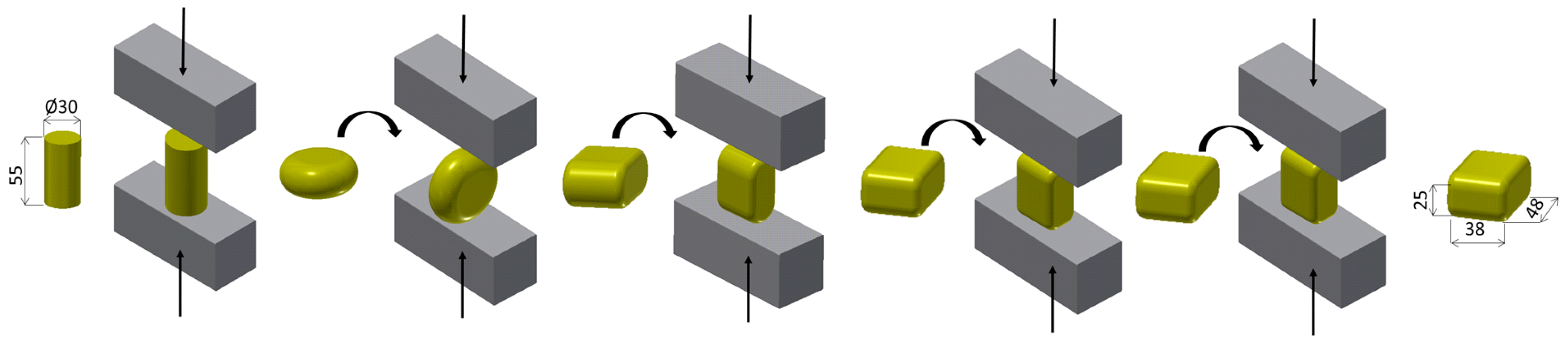
The first step involved heating in a furnace to a specified temperature. The first soaking temperature chosen for investigation was 1200 °C, which is below the solidus temperature. Other temperatures tested were 1220, 1240, and 1280 °C (Figure 4a). A 15-min soaking was followed by cooling in water to 1080 °C. This is an ordinary forging temperature for X210Cr12 steel. After temperature homogenization, the specimen was placed in a furnace at 1080 °C. The next step was open-die forging using four or five blows in a hydraulic press. The first height reduction was 30 mm. The strain rate of 0.56 s−1 was used for each blow. The specimens were rotated for each deformation step to minimalize the deformation inhomogeneity (Figure 5). Because of the mechanism of plastic deformation, the highest value of deformation was located in the specimen center, and therefore all analyses were done from this area. All forming steps were performed at one time without reheating between the individual stages. After forging, the workpiece was quenched in water (regimes 1 to 4). In the next part of the experimental programme (i.e., regime 5), the effects of the post-forming cooling rate were explored while water was replaced with oil as the quenchant. The impact of subsequent tempering on microstructural evolution was examined in regime 6, in which semi-solid processing and forging were followed by tempering at 250 °C for 60 min. The last regime was carried out for the purpose of comparison. In this regime, conventional quenching from 960 °C was followed by tempering at 250 °C for 60 min (regime 7), (Figure 4b).
2.4. Methods of Evaluation
The microstructures of the processed specimens were examined using several techniques. Specimen centers were chosen because they had been subjected to the largest deformation, being the centers of the characteristic diagonal cross pattern of strain. The techniques included light microscopy (LM) and scanning electron microscopy (SEM). Light microscopy was used for description of primary chromium carbides distribution. Scanning electron microscopy was suitable for observation of the fine recrystallized structure and precipitates. The instruments used were a Tescan VEGA 3 SEM (Tescan, Brno, Czech Republic) and Zeiss Crossbeam 340-47-44 (Zeiss, Oberkochen, Germany) for detail analysis. 3% nital (ethanol + HNO3) was used for etching.
The amount of retained austenite was measured by X-ray diffraction analysis. Phase fractions were determined using an AXS Bruker D8 Discover automatic powder diffractometer (Bruker, Karlsruhe, Germany) with a HI-STAR position-sensitive area detector and a cobalt X-ray source (λKα = 0.1790307 nm). The instrument comprises polycapillary optics for focusing the primary X-ray beam into a circular spot with a diameter of 0.5 mm. Measurements were taken at the centers of metallographic sections at diffraction angles in the interval of 25 ÷ 110°2ϑ.
Transmission electron microscopy (TEM) was employed to determine the exact types of carbides and microstructure constituents. Thin foils were prepared by grinding and polishing to 100 μm thickness. Foils of 3 mm diameter were punched and thinned in their central region to approximately 15 μm in a Gatan dimple grinder. They were then ion-polished using the Gatan PIPS II system (PIPS II, Gatan, Inc., Pleasanton, CA, USA) to a thickness suitable for TEM observation (<100 nm). The TEM used for examining the foils was a JEOL JEM-2010 (Jeol, Tokyo, Japan) with a tungsten filament. The acceleration voltage was 200 kV and the resolution was approx. 1.5 nm. Microstructure constituents were imaged and carbide types identified using SAED (selected-area electron diffraction). For selected diffraction spots, bright-field (BF) and dark-field (DF) imaging were employed.
Hardness (HV10) was measured on longitudinal metallographic sections using a Wollpert 432-SVD hardness tester (Wollpert Wilson Instruments, Aachen, Germany), a test load of 10 kg, and a dwell time of 10 s.
3. Results and Discussion
3.1. Microstructural Evolution and Process Parameters
The first trial regime involved a soaking temperature of 1200 °C, which is below the solidus temperature of the material (Table 3). Since deformation was introduced at 1080 °C, the resultant matrix contained very fine recrystallized grains and fine precipitates of secondary chromium carbides (Figure 6a and Figure 7a). Primary chromium carbides remained unaffected because the soaking temperature was below their solidus temperature (Figure 6a). Thorough examination in a scanning electron microscope revealed that austenite grains which had formed while the material was heated to 1200 °C mostly transformed into martensite (Figure 7a). The amount of austenite determined using X-ray analysis was 13% (Table 4). Cr7C3 chromium carbides and Fe3C cementite were detected. This fine martensitic structure with some austenite and carbides had a high hardness of 848 HV10.
In regime 2, soaking at a higher temperature, 1220 °C, failed to dissolve all the sharp-edged chromium carbides (Figure 6b and Figure 7b). This regime, like the previous one, did not cause melting. The resultant microstructure was very similar to the previous one. However, hardness was even lower than in the previous regime: 803 HV10. The retained austenite fraction was 15%.
In regime 3 (Table 3), the soaking temperature was 1240 °C, i.e., above the solidus temperature calculated with JMatPro and confirmed by DSC analysis. Partial melting thus occurred and was manifested in the presence of a ledeburite network in the microstructure. The network formed along the boundaries of polyhedral austenite grains while the workpiece cooled from the soaking temperature to the forming temperature. After that, five-step deformation crushed the network and dispersed its fragments within the martensitic matrix (Figure 6c). The prior austenite grains were no larger than approximately 1 μm (Figure 7c). They decomposed into martensite, although austenite remained in some of them. Its amount was measured by X-ray analysis at 17% (Table 4). The phase in such grains can be described as the M-A constituent. In addition, Cr7C3 carbide and cementite particles were present; their size was around 400 nm. Nearly all sharp-edged primary chromium carbides were eliminated. Hardness was very high: 864 HV10. At this regime the difference between treatment with and without deformation during cooling was clearly visible. The structure without deformation is created by austenite grains surrounded by ledeburite network (Figure 1), which was also reported by Püttgen and Uhlenhaut et al. [8,11]. Deformation taken under the solid temperature lead to a dynamic recrystallization and refinement of austenite grains. The subsequent cooling caused the partial decomposition of the austenite to martensite.
In order to ascertain the impact of a larger liquid fraction on microstructural evolution, another trial regime, No. 4, was carried out with a soaking temperature of 1280 °C. After soaking and five-step deformation, the workpiece was quenched in water (Table 3). The microstructure consisted of fine grains of M-A constituent, fine chromium carbide precipitates, and cementite (Figure 6d and Figure 7d). Primary chromium carbides dissolved. Higher soaking temperature led to higher liquid fraction and, in turn, to a larger volume fraction of ledeburite network. Hardness was 866 HV10. The retained austenite volume fraction decreased to 8% (Table 4).
Using the regimes described below, the effects of the cooling rate after soaking on microstructural evolution were studied. Regime 5 had a soaking temperature of 1240 °C and involved oil quenching, instead of the water quenching used in the previous regimes 3. Other process parameters remained unchanged (Table 3). The resultant microstructure exhibited no major differences from the regime 3 with cooling to the water (Figure 6e and Figure 7e). Only size of precipitated carbides was slightly higher and they were more spheroidized, which was caused by slower cooling rate. Hardness was lower than in the previous regimes: 778 HV10. The reasons for the lower hardness may include the higher retained austenite fraction, which was 21% (Table 4), and a smaller proportion of carbides (9% Cr7C3 and 9% Fe3C). Since the workpiece cooled longer from the forming temperature of 1080 °C, carbon could migrate and stabilize a larger amount of retained austenite.
Since the final hardness values were still high, tempering at 250 °C for 60 min was added in the next trial regime, No. 6, which was otherwise identical to regime 5. The resultant matrix again comprised the M-A constituent and fine chromium carbides and cementite (Figure 6f and Figure 7f). Tempering caused further growth of the precipitates (Figure 7f), but did not affect the fraction of retained austenite (Table 4). During the tempering, no migration of carbon from retained austenite occurred to the matrix and austenite remained stable even when cooled to RT. Tempering of the matrix led also to the decrease of the hardness of about 100 HV10 to 677 HV10. In comparison to Rogal et al. [20] the influence of tempering temperature on hardness was much significant. They observed the first increase of hardness after tempering at 525 °C. In their case it was caused by decomposition of high fraction of austenite from SSP. On the other side the thermomechanical treatment in our case led to lower fraction of austenite, so it would be interesting to observe the next microstructure and hardness evolution at higher tempering temperature.
For the sake of comparison, an additional regime was carried out which involved soaking at 960 °C, conventional oil quenching, and tempering in a furnace at 250 °C for 60 min (regime 7) (Table 3). Unlike its predecessors, this regime did not involve hot forging. The resultant microstructure differed from the previous ones (Figure 8a,b). It was coarser and contained heavily-tempered martensite with globular primary chromium carbides. Fine chromium carbides and cementite were present (Figure 8b). The amount of retained austenite was small, a mere 6% (Table 4). This was due to its insufficient chemical stabilization during heating to a lower temperature. Hardness of 609 HV10 was the lowest of all the regimes treated with the semi-solid processing. But in comparison to the initial annealed state the change of the matrix from ferrite to tempered martensite brought very high hardness increase.
3.2. Microstructure Observation Using Transmission Electron Microscopy
Phase transformations during semi-solid processing are highly complex. The resultant microstructures are therefore intricate and require detailed analysis of the individual constituents. This was performed on thin foils in a transmission electron microscope. The foils were prepared from workpieces from regimes 1 and 3. Regime 1 involved a low soaking temperature of 1200 °C, and therefore caused no melting. Regime 3 had a soaking temperature of 1240 °C, which led to partial melting.
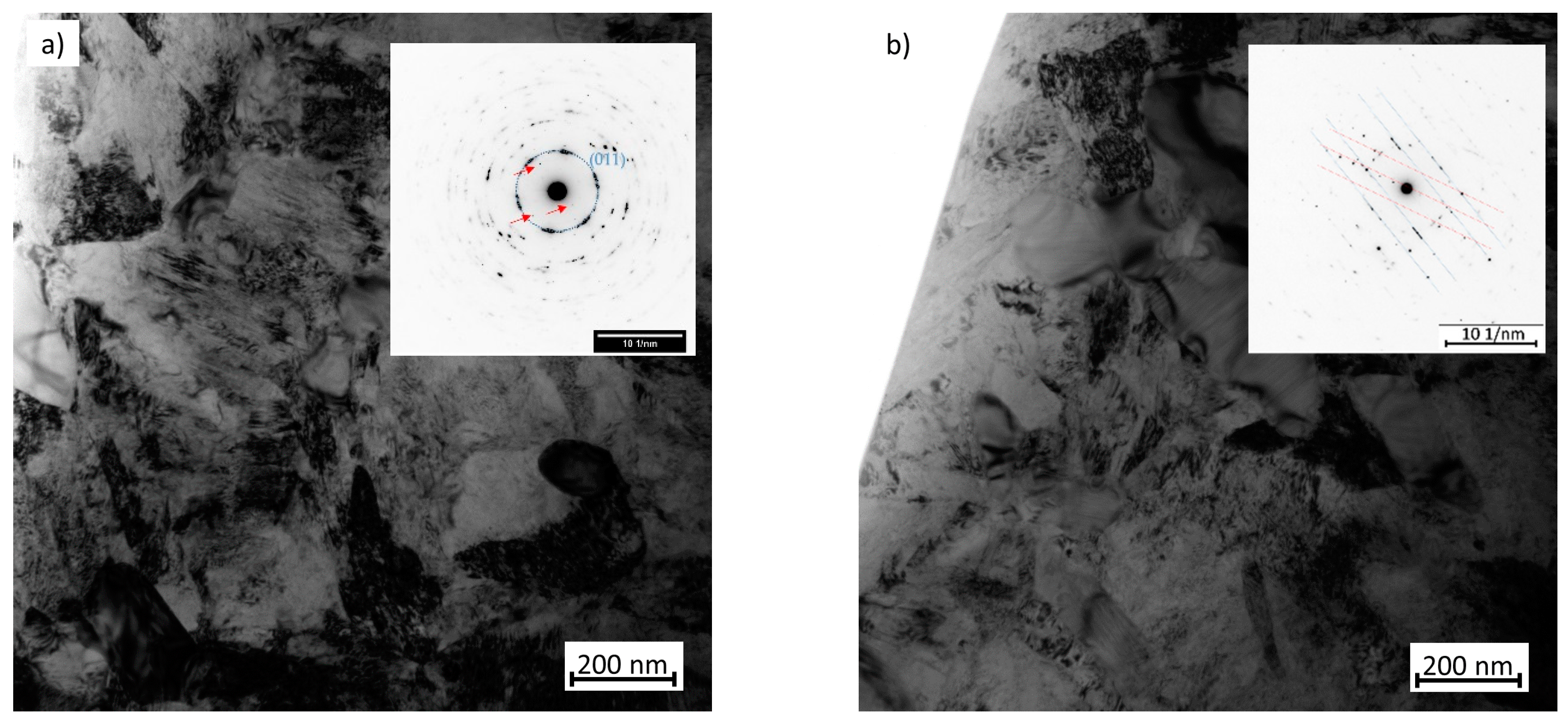
The specimen obtained with regime 1 had a very fine ferritic-martensitic structure. Its grain size was several hundred nanometers. Some retained austenite was present. Various martensite morphologies were found: lath and twinned martensite (Figure 9a). The matrix contained Fe3C cementite particles and clusters of particles of differing sizes, approximately several hundred nanometers (Figure 9b). The cementite particles were dislocation-free. In addition to cementite, Cr23C6 chromium carbides with cubic symmetry were present (Figure 10a,b). However, the presence of Cr23C6 carbides was not confirmed by X-ray diffraction. The reason is that with the highest-intensity diffraction lines, the first one being close to 52°2Theta and the second approx. 59°2Theta, the lines for both types of carbides may overlap easily. Moreover, the Cr23C6 carbides were expected to be in the minority.
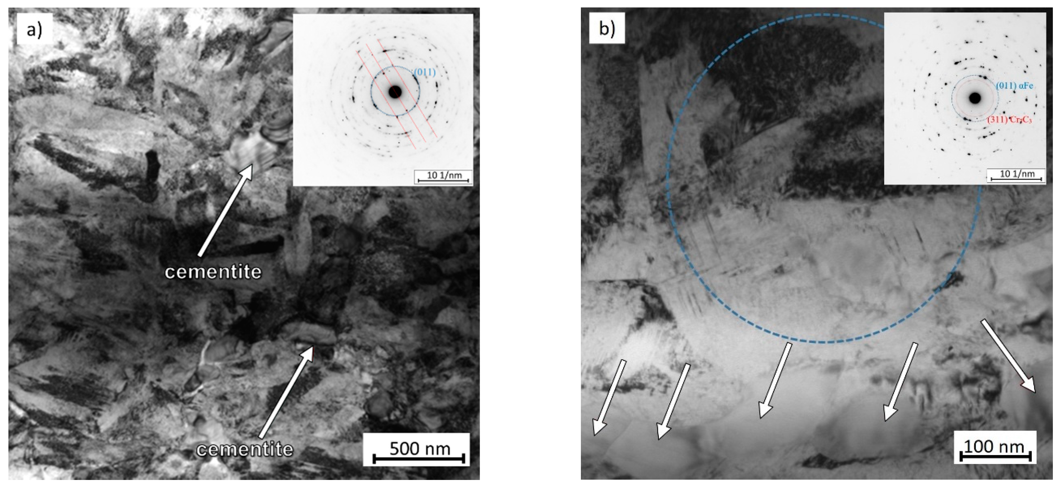
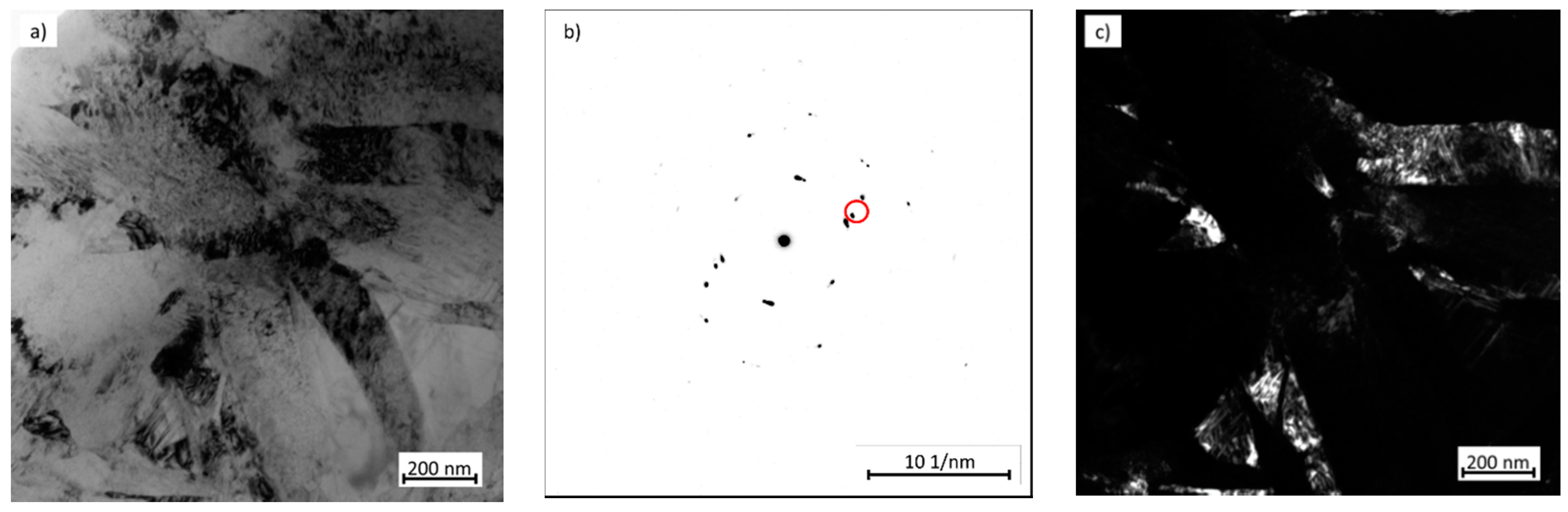
The microstructure of the specimen from regime 3, in which the soaking temperature was 1240 °C, was very similar. It consisted of very fine ferrite and martensite (α-Fe, bcc) with a grain size of several hundred nanometers (Figure 11). Besides martensite, the other phases identified included retained austenite (γ-Fe, fcc) and Fe3C cementite with orthorhombic symmetry and lattice parameters a = 0.4514 nm, b = 0.5078 nm, and c = 0.6729 nm. Cementite particles formed large clusters approx. 1 µm in size and smaller clusters of about 100–200 nm. The interiors of the cementite particles were clear and free of dislocations. In addition, very small carbides of the Cr7C3 type with a hexagonal structure were identified (Figure 12). These findings are in agreement with the results of the X-ray diffraction phase analysis.
3.3. Micro-Tensile Test (M-TT)
Stress-strain characteristics were determined using uniaxial tensile testing. As the amount of experimental material was small, it was impossible to make standard test samples in accordance with ISO 6892-1 [21]. In addition, it was necessary to test only a small volume of material from the center of the workpiece. Hence, miniature test pieces had to be used. For this purpose, the recently-developed micro-tensile test (M-TT) technique for materials with low ductility was chosen [22,23,24].
M-TT is carried out using a special LabControl test device of 5 kN capacity. Its linear motor runs smoothly at very slow speeds. The test piece is clamped in special flat jaws which have been developed for this purpose. The axial extension is captured with a high-speed CCD camera integrated into the ARAMIS system that relies on digital image correlation (DIC). As the force and extension data are captured accurately, the record need not be specially processed and the evaluation can follow the standard procedure [21].
An M-TT specimen had a thickness of 0.5 mm and parallel length of 2 mm (Figure 13). The transition region between the parallel length region and the shoulder has a very moderate slope in order to eliminate notch effects. The specimens were made using a wire EDM machine and all their surfaces were then ground and polished. No less than three valid measurements were taken for each condition examined. Since brittle fracture was expected to occur, the strain rate was set at 0.00025 s−1, which corresponds to the lower values recommended by the standard [21].
The material in as-received condition had a ferritic matrix, an ultimate strength of 676 MPa and elongation A5 = 16% (Table 5). After semi-solid processing and subsequent oil quenching from the forming temperature (regime 5), the ultimate strength was 1985 MPa and elongation was very low, with an average value in the vicinity of 1%. Conventional quenching and tempering (regime 7) yielded similar results (Table 5). The ultimate strength decreased to 1810 MPa and elongation increased only slightly. The stress-strain curves are shown in Figure 14. The higher ultimate strength in the semi-solid-processed material results from a very fine microstructure with a grain size of approx. 1 μm, as opposed to quenched and tempered material with uniformly-dispersed fine carbides.
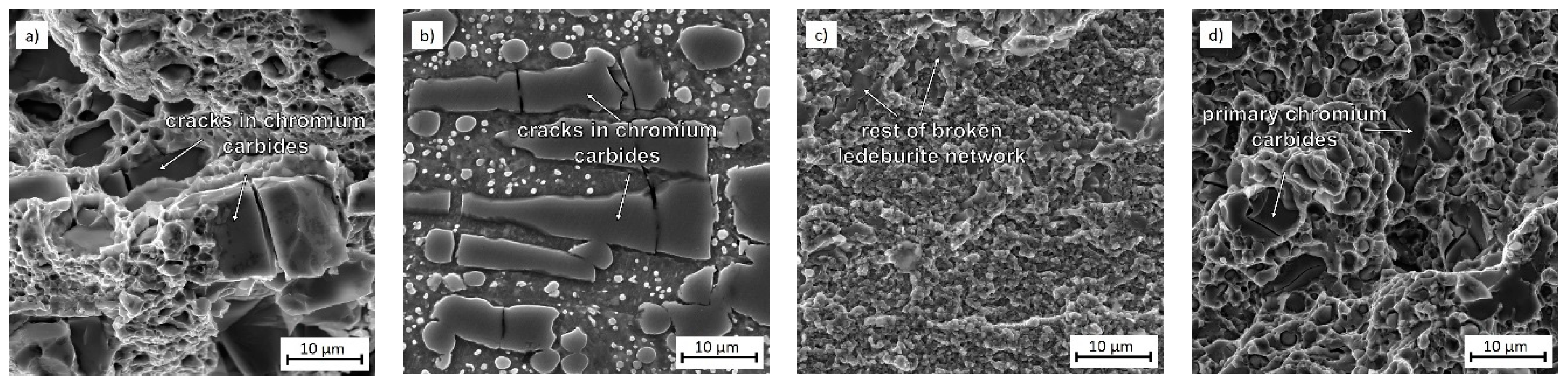
The tests were complemented with fracture surface observation. The fracture in the as-received material was of a mixed nature, showing both dimples in the ferritic matrix, which are characteristic of ductile fracture, and brittle fracture facets (Figure 15a). The facets corresponded to the presence of primary chromium carbides. Cracks in the chromium carbides perpendicular to the load direction were found on a polished and etched metallographic cross section of the fracture region (Figure 15b). Semi-solid processing followed by oil quenching (regime 5) produced a very fine microstructure, due to which the type of fracture surface was very difficult to identify (Figure 15c). Due to the high hardness and predominantly martensitic microstructure, the fracture was brittle. In the fracture area the rest of the ledeburite network was also observed. The fracture in the conventionally quenched and tempered material (regime 7) was of a mixed nature. Brittle fracture facets were found in the locations of chromium carbides (Figure 15d).
4. Conclusions
An unconventional semi-solid processing route was tested in an effort to eliminate sharp-edged primary chromium carbides from the microstructure of X210Cr12 tool steel as well as refine the grains.
It was found that the soaking temperature must be at least 1240 °C to obtain a liquid phase and to achieve almost complete dissolution of the sharp-edged primary chromium carbides. Deformation introduced at 1080 °C led not only to substantial grain refinement and initiated dynamic recrystallization, but also to complete breaking up and dispersion of ledeburite network. The microstructure contained very fine previous austenite grains filled with the M-A constituent whose size was less than 1 μm, and very fine Fe3C and Cr7C3 carbides with the hardness 860 HV10. The presence of martensite in both morphologies—lath as well as twinned was confirmed. Thanks to the micro-tensile testing (M-TT) and its miniature test pieces, properties were determined within relatively small and homogeneous regions. The conventional treatment produced an ultimate strength of 1810 MPa and low elongation of 1%. Using semi-solid processing, the ultimate strength was successfully increased to 1985 MPa without any increase in elongation.
Author Contributions
Conceptualization, H.J., K.R.; Methodology, K.O., K.R., P.K.; Investigation, H.J., K.R., K.O., P.K.; Resources, H.J.; Data Curation, H.J.; Writing-Original Draft Preparation, H.J., K.R.; Writing-Review & Editing, K.O., P.K.; Project Administration, H.J.; Funding Acquisition, H.J.
Funding
This research was funded by Ministry of Education of the Czech Republic under project LO1502 “Development of the Regional Technological Institute” under the auspices of National Sustainability Programme I.
Acknowledgments
The authors thank to Research Centre Řež for the analysis on the transmission electron microscope and to Faculty of Materials Science and Technology of the Slovak University of Technology in Trnava for calculation in Thermo-Calc.
Conflicts of Interest
The authors declare no conflict of interest.
References
- Hoyoung, K.; Jun-Yun, K.; Dongmin, S.; Tae-Ho, L.; Kyung-Mox, C. Evolution of carbides in cold-work tool steels. Mater. Charact. 2015, 107, 376–385. [Google Scholar] [CrossRef]
- Wang, J.; Guo, W.; Sun, H.; Li, H.; Gou, H.; Zhang, J. Plastic deformation behaviours and hardening mechanism of M7C3 carbid. Mater. Sci. Eng. A 2016, 662, 88–94. [Google Scholar] [CrossRef]
- Casellas, D.; Caro, J.; Molas, S.; Prado, J.M.; Valls, I. Fracture toughness of carbides in tool steels evaluated by nanoindentation. Acta Mater. 2007, 55, 4277–4286. [Google Scholar] [CrossRef]
- Bombac, D.; Fazarinc, M.; Saha Podder, A.; Kugler, G. Study of Carbide Evolution During Thermo-mechanical Processing of AISI D2 Tool Steel. J. Mater. Eng. Perform. 2013, 22, 742–747. [Google Scholar] [CrossRef]
- Song, T.; Kang, Y.; Zhao, A. Semi-solid rolling process of steel strips. J. Mater. Process. Technol. 2008, 198, 291–299. [Google Scholar] [CrossRef]
- Rassili, A.; Atkinson, H.V. A review of steel thixoforming. Trans. Nonferrous Met. Soc. China 2010, 20, 1048–1054. [Google Scholar] [CrossRef]
- Jirková, H.; Aišman, D.; Mašek, B. Unconventional structure of X210Cr12 steel obtained by thixoforming. J. Alloy. Compd. 2010, 504, S500–S503. [Google Scholar] [CrossRef]
- Puttgen, W.; Hallstedt, B.; Bleck, W.; Uggowitzer, P.J. On the microstructure formation in chromium steels rapidly cooled from the semi-solid state. Acta Mater. 2007, 55, 1033–1042. [Google Scholar] [CrossRef]
- Balan, T.; Becker, E.; Langlois, L.; Bigot, R. A new route for semi-solid steel forging. CIRP Ann. 2017, 66, 297–300. [Google Scholar] [CrossRef] [Green Version]
- Kopp, R.; Kallweit, J.; Möller, T.; Seidl, I. Forming and joining of commercial steel grades in the semi-solid state. J. Mater. Process. Technol. 2002, 130–131, 562–568. [Google Scholar] [CrossRef]
- Uhlenhaut, D.I.; Kradolfer, J.; Puttgen, W.; Loffler, J.F.; Uggowitzer, P.J. Structure and properties of a hypoeutectic chromium steel processed in the semi-solid state. Acta Mater. 2006, 54, 2727–2734. [Google Scholar] [CrossRef]
- Aišman, D.; Jirková, H.; Kučerová, L.; Mašek, B. Metastable structure of austenite base obtained by rapid solidification in a semi-solid state. J. Alloy. Compd. 2011, 509, S312–S315. [Google Scholar] [CrossRef]
- Aišman, D.; Jirková, H.; Mašek, B. The influence of deformation and cooling parameters after transition through semi-solid state on structure development of ledeburite steel. J. Alloy. Compd. 2012, 536, S204–S207. [Google Scholar] [CrossRef]
- Rogal, Ł.; Dutkiewicz, J. Deformation behavior of high strength X210CrW12 steel after semi-solid processing. Mater. Sci. Eng. A 2014, 603, 93–97. [Google Scholar] [CrossRef]
- Mašek, B.; Aišman, D.; Jirková, H.; Wurster, S. Micro-compression test of thixoformed austenite. Solid State Phenom. 2013, 192, 215–218. [Google Scholar] [CrossRef]
- ČSN 41 9436. Ocel 19436 chromová (Tool Steel 19 436); Český Normalizační Institut: Praha, Czech Republic, 1994.
- Bučovice, JKZ. X210Cr12. Available online: http://www.jkz.cz/cs/produkty/nastrojove-oceli/pro-prace-za-studena/w-nr-12080/ (accessed on 20 June 2017).
- JMatPro, Release 9.0, Sente Software Ltd.: Guildford, UK, 2016.
- Thermo-Calc, 2017a, Thermo-Calc Software AB: Pittsburgh, PA, USA, 2018.
- Rorgal, Ł.; Dutkiewicz, J.; Szklarz, Z.; Zimowski, S.; Kot, M.; Zimowski, S. Mechanical properties and corrosion resistance of steel X210CrW12 after semi-solid processing and heat treatment. Mater. Charact. 2014, 88, 100–110. [Google Scholar] [CrossRef]
- International Organization for Standardization (ISO). ISO 6892-1:2016: Metallic Materials—Tensile Testing—Part 1: Method of Test at Room Temperature; ISO: Geneva, Switzerland, 2016. [Google Scholar]
- Konopík, P.; Džugan, J. Determination of Tensile Properties of Low Carbon Steel and Alloyed Steel 34CrNiMo6 by Small Punch Test and Micro-Tensile Test. In Proceedings of the 2nd International conference—Determination of Mechanical Properties of Materials by Small Punch and Other Miniature Techniques, Ostrava, Czech Republic, 2–4 October 2012; Matocha, K., Hurst, R., Sun, W., Eds.; Ocelot: Ostrava-Vítkovice, Czech Republic, 2012; pp. 319–328. [Google Scholar]
- Rund, M.; Procházka, R.; Konopík, P.; Džugan, J.; Folgar, H. Investigation of Sample-size Influence on Tensile Test Results at Different Strain Rate. Procedia Eng. 2015, 114, 410–415. [Google Scholar] [CrossRef]
- Prochazka, R.; Dzugan, J.; Konopik, P.; Rund, M. Investigation of high-strength stainless steel using small specimen test techniques—Tensile and fatigue properties. In Proceedings of the 7th International Conference on Mechanics and Materials in Design (M2D), Albufeira, Portugal, 11–15 June 2017; Gomes, J.F.S., Meguid, S.A., Eds.; INEGI/FEUP: Porto, Portugal, 2017; pp. 343–354. [Google Scholar]
Figure 1.
(a) As-received condition of the X210Cr12 steel: primary Cr7C3 carbides and fine cementite in a ferritic matrix, light microscope; (b) semi-solid processed microstructure, soaking temperature: 1240 °C, polygonal austenite grains, ledeburite network, light microscope.
Figure 1.
(a) As-received condition of the X210Cr12 steel: primary Cr7C3 carbides and fine cementite in a ferritic matrix, light microscope; (b) semi-solid processed microstructure, soaking temperature: 1240 °C, polygonal austenite grains, ledeburite network, light microscope.

Figure 2.
Dependence of phase fractions on temperature, as calculated with JMatPro and Thermo-Calc.

Figure 3.
(a) Container made of a low-carbon steel and a specimen of the X210Cr12 steel; (b) forging in a hydraulic press.
Figure 3.
(a) Container made of a low-carbon steel and a specimen of the X210Cr12 steel; (b) forging in a hydraulic press.
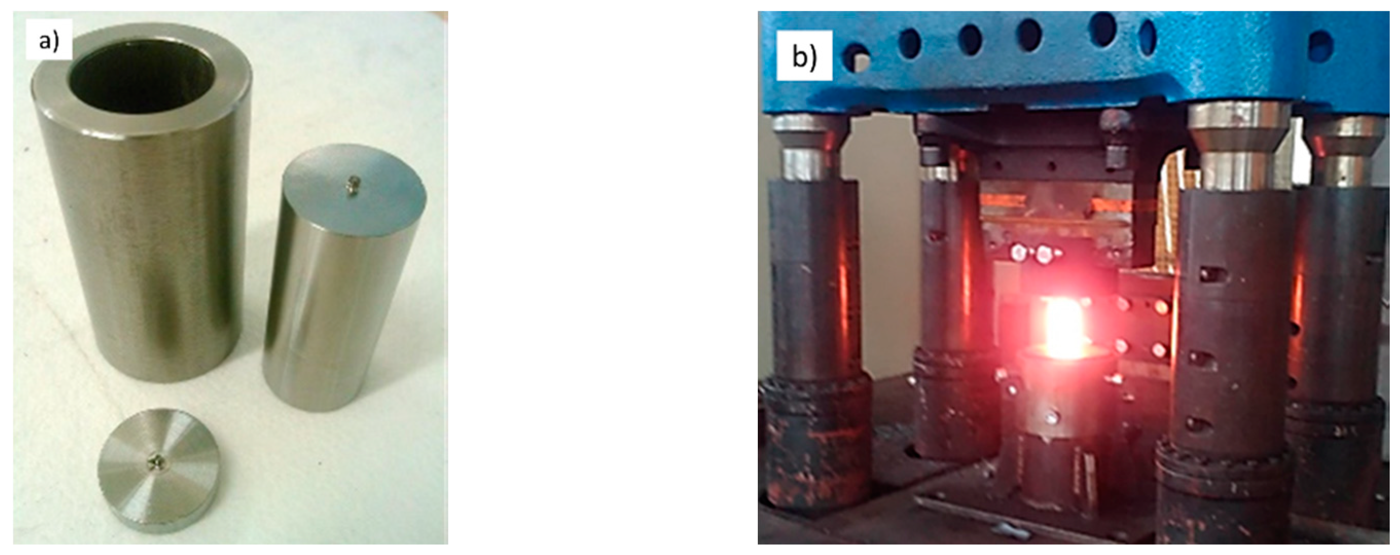
Figure 4.
(a) Semi-solid processing routes, regimes 1–6; (b) quenching and tempering route, regime 7.
Figure 4.
(a) Semi-solid processing routes, regimes 1–6; (b) quenching and tempering route, regime 7.
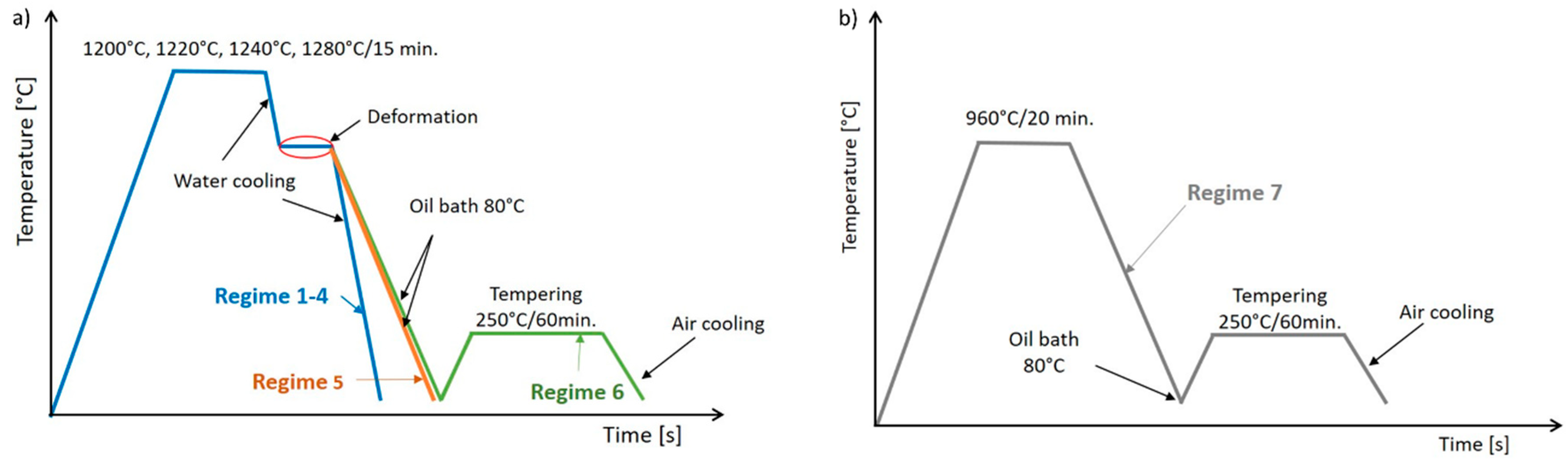
Figure 5.
Scheme of the forging process at the temperature of 1080 °C.

Figure 6.
Micrographs from light microscope of semi-solid-processed and subsequently press-formed material: (a) 1200 °C/water (regime 1); (b) 1220 °C/water (regime 2); (c) 1240 °C/water (regime 3); (d) 1280 °C/water (regime 4); (e) 1240 °C/oil (regime 5); (f) 1240 °C/oil–250 °C/60 min (regime 6), light micrographs.
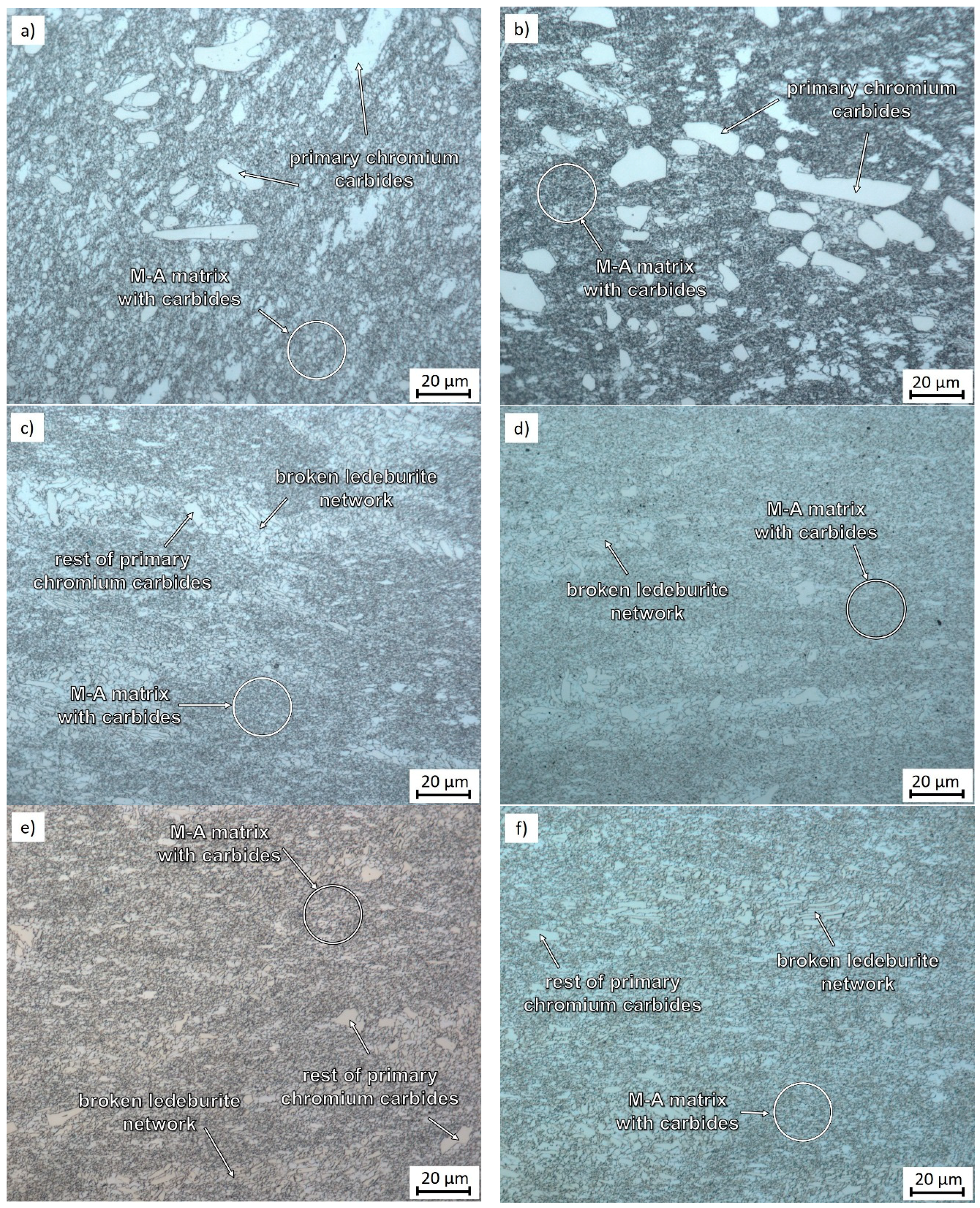
Figure 7.
Detail micrographs from scanning electron microscope of semi-solid-processed and subsequently press-formed material: (a) 1200 °C/water (regime 1); (b) 1220 °C/water (regime 2); (c) 1240 °C/water (regime 3); (d) 1280 °C/water (regime 4); (e) 1240 °C/oil (regime 5); (f) 1240 °C/oil–250 °C/60 min (regime 6), scanning electron micrographs.
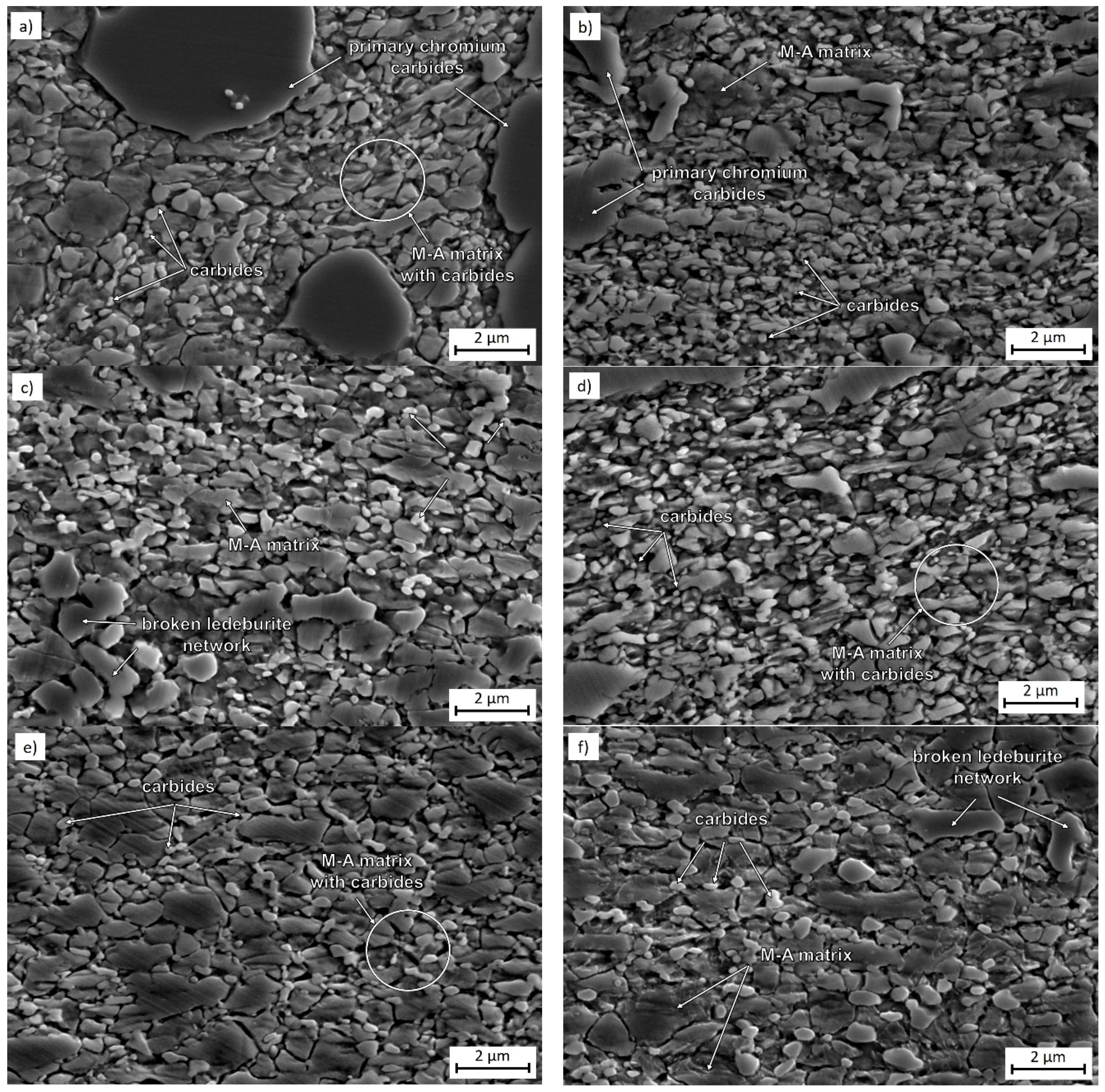
Figure 8.
Regime 7—960 °C/oil–250 °C/60 min: a matrix of tempered martensite, spheroidised primary chromium carbides, and cementite, (a) optical micrograph; (b) detail scanning electron micrograph.
Figure 8.
Regime 7—960 °C/oil–250 °C/60 min: a matrix of tempered martensite, spheroidised primary chromium carbides, and cementite, (a) optical micrograph; (b) detail scanning electron micrograph.
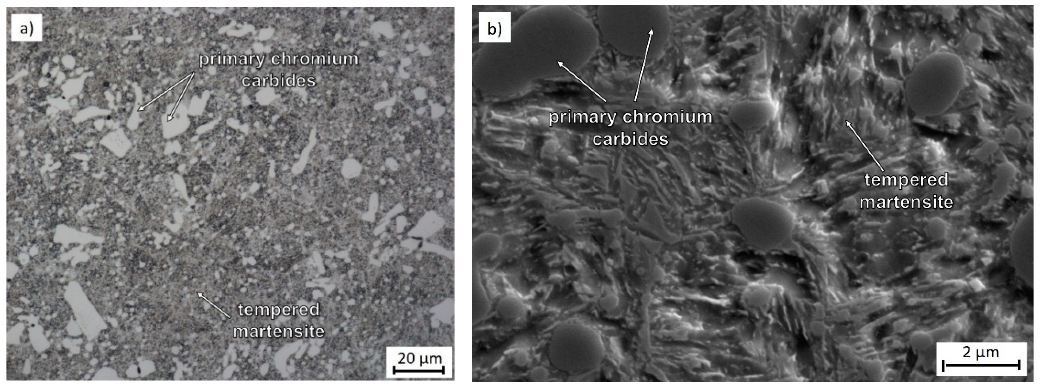
Figure 9.
Regime 1: 1200 °C/water: general micrographs, (a) lath martensite and twinned martensite, part of an Fe3C cementite particle is visible at the edge of the micrograph; (b) smaller cementite particles in the martensitic matrix.
Figure 9.
Regime 1: 1200 °C/water: general micrographs, (a) lath martensite and twinned martensite, part of an Fe3C cementite particle is visible at the edge of the micrograph; (b) smaller cementite particles in the martensitic matrix.
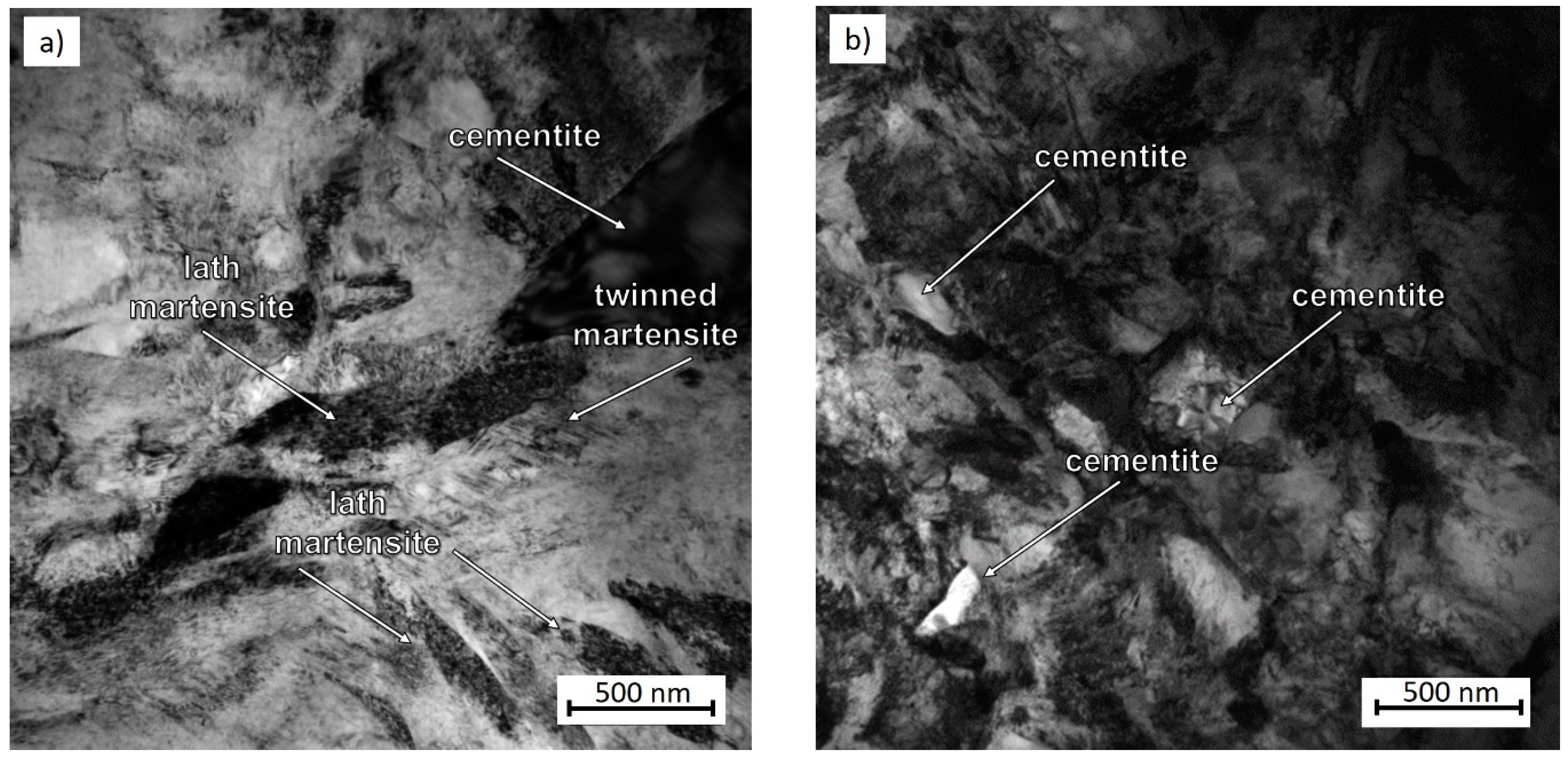
Figure 10.
Regime 1: 1200 °C/water: (a) BF (bright-field) micrograph, particles of Fe3C cementite and carbides are visible in the ferritic-martensitic matrix; the inset shows the related SAED pattern with a marked circle associated with the (011) αFe reflections, the sharp spots outside the circle indicate carbides (marked with an arrow); (b) region with a vast number of Fe3C cementite and Cr23C6 carbide particles with their SAED pattern in which Fe3C cementite spots are marked in blue and Cr23C6 carbide spots in red.

Figure 11.
Regime 3: 1240 °C/water, BF micrograph: (a) fine-grained matrix with twinned martensite, retained austenite and Fe3C cementite particles; related SAED pattern with diffraction spots of αFe ferrite (blue circle) and cementite (red); (b) ferrite region with locations of high dislocation density, sparse small carbide particles with a size of several nanometres, and undeformed cementite—arrows; the area examined using diffraction is indicated in blue; related SAED pattern with ferrite reflections and diffraction spots of hexagonal carbides indicated, the latter correspond to (311) planes in Cr7C3.

Figure 12.
Regime 3: 1240 °C/water: (a) BF micrograph; (b) related SAED pattern with a reflection of γFe austenite (red) used for DF imaging; (c) DF micrograph showing the distribution of retained austenite.
Figure 12.
Regime 3: 1240 °C/water: (a) BF micrograph; (b) related SAED pattern with a reflection of γFe austenite (red) used for DF imaging; (c) DF micrograph showing the distribution of retained austenite.

Figure 13.
Geometry of an M-TT test specimen for testing brittle materials.
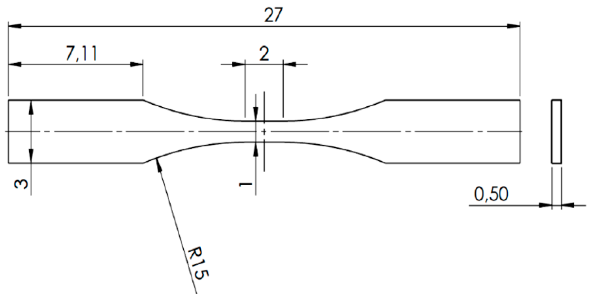
Figure 14.
Stress-strain curves after micro-tensile test with significant difference between samples in initial state with ferritic matrix (red curve), after conventional heat treatment (green curve), and after semi-solid processing with forming (blue curve).
Figure 14.
Stress-strain curves after micro-tensile test with significant difference between samples in initial state with ferritic matrix (red curve), after conventional heat treatment (green curve), and after semi-solid processing with forming (blue curve).
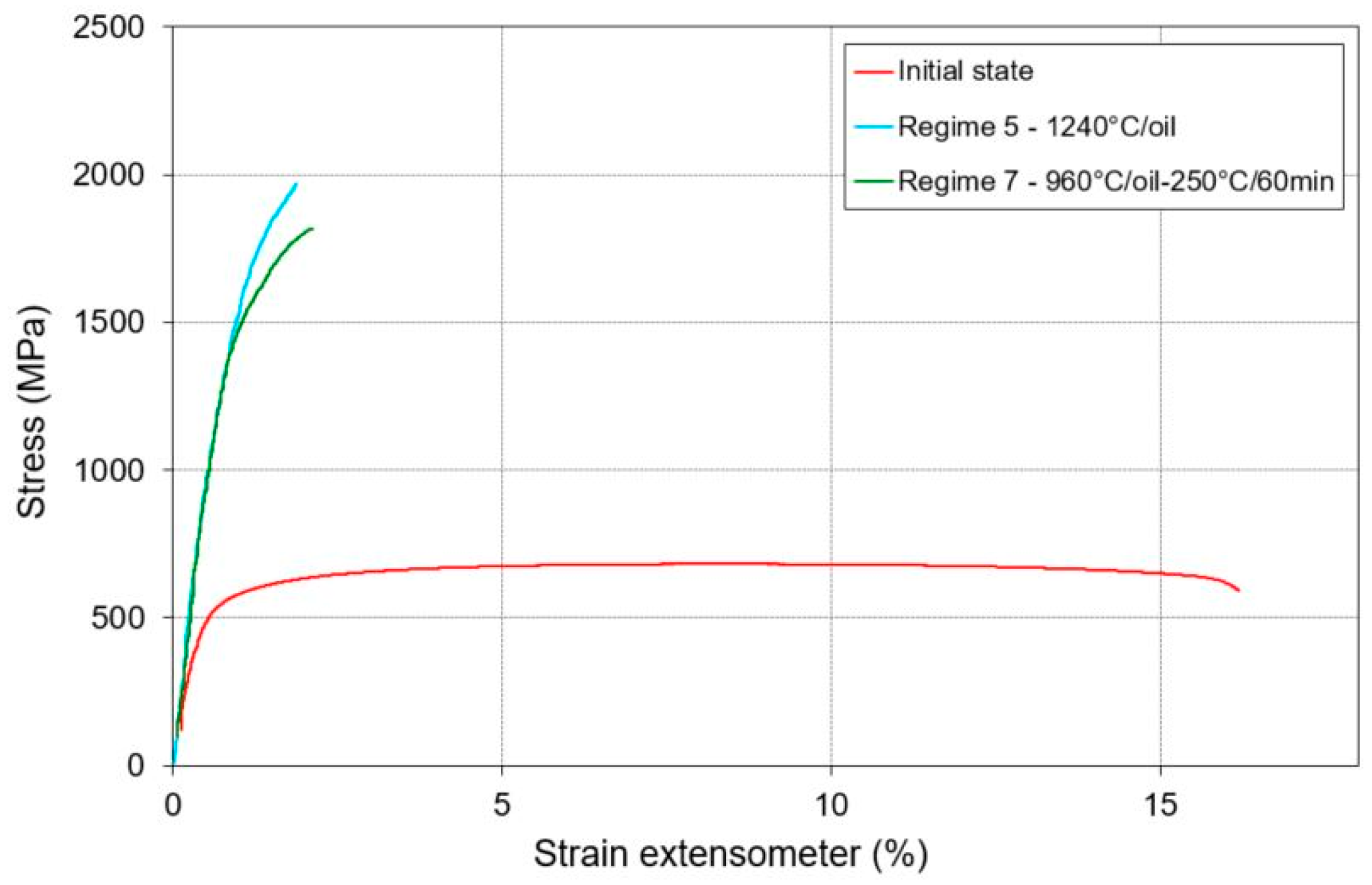
Figure 15.
(a) As-received condition—fracture surface in a tensile test specimen, mixed fracture mode, (b) As-received condition—cracks in chromium carbides near the fracture location, metallographic cross section (c) Regime 5—1240 °C/oil: tensile fracture surface, brittle fracture, (d) Regime 7—960 °C/oil–250 °C/60 min: tensile fracture surface: brittle fracture.

Table 1.
Chemical composition (wt. %) and fractions of individual phases (vol. %) of X210Cr12 steel.
Table 1.
Chemical composition (wt. %) and fractions of individual phases (vol. %) of X210Cr12 steel.
| C | Cr | Mn | Si | Ni | P | S | HV10 (–) | BCC-Fe | Cr7C3 | Fe3C |
|---|---|---|---|---|---|---|---|---|---|---|
| 1.8 | 11 | 0.2 | 0.2 | 0.5 max | 0.03 max | 0.01 max | 220 | 70 | 6 | 24 |
Table 2.
Chemical composition (wt. %) and phase transformation temperatures of X210Cr12 steel.
| JMatPro | Thermo-Calc | DSC | |||
|---|---|---|---|---|---|
| Tsolidus (°C) | Tliquidus (°C) | Tsolidus (°C) | Tliquidus (°C) | Tsolidus (°C) | Tliquidus (°C) |
| 1225 | 1373 | 1245 | 1376 | 1237 | 1416 |
Table 3.
Parameters of heat treatment and hardness values.
| Regime | Soaking Temp. (°C) | Time at Temp. (min) | Forging Temp. (°C) | Time at Temp. (min) | Number of Def. Steps | Cooling Medium | Tempering Temp. (°C)/Time (min) | HV10 (–) |
|---|---|---|---|---|---|---|---|---|
| 1 | 1200 | 15 | 1080 | 1.5 | 4 | Water | - | 848 |
| 2 | 1220 | 15 | 1080 | 1.5 | 4 | Water | - | 803 |
| 3 | 1240 | 15 | 1080 | 1.5 | 5 | Water | - | 864 |
| 4 | 1280 | 15 | 1080 | 1.5 | 5 | Water | - | 866 |
| 5 | 1240 | 15 | 1080 | 1.5 | 5 | Oil 80 °C | - | 778 |
| 6 | 1240 | 15 | 1080 | 1.5 | 5 | Oil 80 °C | 250/60 | 677 |
| 7 | 960 | 20 | - | - | - | Oil 80 °C | 250/60 | 535 |
Table 4.
Phase fractions determined by X-ray diffraction analysis after various experimental regimes.
Table 4.
Phase fractions determined by X-ray diffraction analysis after various experimental regimes.
| Regime No. | Process | FCC-Fe (vol. %) | BCC-Fe (vol. %) | Cr7C3 (vol. %) | Fe3C (vol. %) |
|---|---|---|---|---|---|
| 1 | 1200 °C/1080 °C forging/water | 13 | 56 | 17 | 14 |
| 2 | 1220 °C/1080 °C forging/water | 15 | 49 | 16 | 20 |
| 3 | 1240 °C/1080 °C forging/water | 17 | 48 | 18 | 17 |
| 4 | 1280 °C/1080 °C forging/water | 8 | 51 | 20 | 21 |
| 5 | 1240 °C/1080 °C forging/oil | 21 | 59 | 11 | 9 |
| 6 | 1240 °C/1080 °C forging/oil–250 °C/60 min | 24 | 48 | 17 | 6 |
| 7 | 960 °C/oil–250 °C/60 min | 6 | 65 | 14 | 15 |
Table 5.
Micro-tensile test data for selected regimes.
| Regime | Process | Rp0.2 (OYS) (%) | Rm (UTS) (%) | A5 (%) | Z (%) |
|---|---|---|---|---|---|
| – | Initial condition | 541 | 676 | 16.3 | 24.8 |
| 5 | 1240 °C/oil | 1466 | 1985 | 1.0 | 5.8 |
| 7 | 960 °C/oil–250 °C/60 min | 1413 | 1810 | 1.3 | 4.5 |
© 2018 by the authors. Licensee MDPI, Basel, Switzerland. This article is an open access article distributed under the terms and conditions of the Creative Commons Attribution (CC BY) license (http://creativecommons.org/licenses/by/4.0/).
Share and Cite
MDPI and ACS Style
Jirková, H.; Rubešová, K.; Konopík, P.; Opatová, K. Effect of the Parameters of Semi-Solid Processing on the Elimination of Sharp-Edged Primary Chromium Carbides from Tool Steel. Metals 2018, 8, 713. https://doi.org/10.3390/met8090713
AMA Style
Jirková H, Rubešová K, Konopík P, Opatová K. Effect of the Parameters of Semi-Solid Processing on the Elimination of Sharp-Edged Primary Chromium Carbides from Tool Steel. Metals. 2018; 8(9):713. https://doi.org/10.3390/met8090713
Chicago/Turabian StyleJirková, Hana, Kateřina Rubešová, Pavel Konopík, and Kateřina Opatová. 2018. "Effect of the Parameters of Semi-Solid Processing on the Elimination of Sharp-Edged Primary Chromium Carbides from Tool Steel" Metals 8, no. 9: 713. https://doi.org/10.3390/met8090713
Note that from the first issue of 2016, this journal uses article numbers instead of page numbers. See further details here.