Article

Effect of CaCl2 on Microstructure of Calciothermic Reduction Products of Ti2O3 to Prepare Porous Titanium

1
National Engineering Laboratory for Vacuum Metallurgy, Kunming University of Science and Technology, Kunming 650093, China
2
State Key Laboratory of Complex Nonferrous Metal Resources Clear Utilization, Kunming University of Science and Technology, Kunming 650093, China
3
Faculty of Metallurgy and Energy Engineering, Kunming University of Science and Technology, Kunming 650093, China
4
Yunnan Provincial Key Laboratory for Nonferrous Vacuum Metallurgy, Kunming University of Science and Technology, Kunming 650093, China
*
Author to whom correspondence should be addressed.
Metals 2018, 8(9), 698; https://doi.org/10.3390/met8090698
Submission received: 13 August 2018 / Revised: 3 September 2018 / Accepted: 3 September 2018 / Published: 5 September 2018

Abstract

:
The compound CaCl2 plays a significant role in the process of direct calciothermic reduction of Ti2O3 to prepare porous titanium. In this paper, the effect of CaCl2 on reduction products by calciothermic reduction of Ti2O3 was investigated. Results show that the distribution of CaCl2 in reduction preform influences particle size and morphology differences in reduction products both on the surface and the inside. The CaCl2 is transferred to the surface of the Ti2O3 preform due to its volatilization before and throughout reduction. The content of CaCl2 in the surface zone of Ti2O3 preform is significantly higher than that in the interior during the reduction process, contributing to the formation of large Ti particles with a smooth shape on the surface, and small Ti particles with inherited morphology of Ti2O3 inside. More CaCl2 causes the aggregation of Ti particles to form large Ti particles which are advantageous as they connect and form a more solid porous titanium structure. The presence of a small amount of CaCl2 in the interior also results in the coexistence of small Ti and CaO particles, forming a loose structure with uniform distribution.

1. Introduction

Porous titanium is a widely applicable material in the chemical, petroleum, and pharmaceutical industries due to the excellent properties it inherits from titanium and its alloys [1,2,3]. It is also low density, and displays superior corrosion resistance, a high specific strength, and biocompatibility. In the field of biomedicine, porous titanium is an increasingly attractive choice for bone implants because it can diminish the stress shielding phenomenon and enhance the interfacial strength of the implant [4,5,6,7]. Porous titanium can be produced by various techniques, including the metal powder sintering technique [8,9], anodic oxidation technology [10], 3D printing technology [11], and spark plasma sintering technology [12,13].
Almost all reported methods to prepare porous titanium use titanium powder or titanium hydride as a raw material, and require the raw materials to have particular qualities like low oxygen content [14,15]. Based on the research of Xu, metallic titanium has been prepared successfully via calciothermic reduction of titanium oxide with CaCl2 as an additive under vacuum conditions [16,17]. Lei and Xu proposed and verified a new method of preparing porous titanium by calcium vapor reduction of porous calcium titanate, omitting the preparation process of metallic titanium, and applied the concept of metallurgical material integration [18]. Using this concept, the porous titanium structure was successfully fabricated but porous titanium block was difficult to obtain for a higher volume ratio of CaO and Ti in reduction products when porous CaTiO3 and TiO2 were used as precursors, respectively. In the process of reduction, they considered using calcium metal as reductant, for the obtained titanium has a low oxygen content. The by-product CaO was leached by dilute hydrochloric acid to gain CaCl2 which can be recycled partly and be electrolysed to prepare calcium for reduction [17,19]. Recently, porous titanium blocks with two different microstructures were prepared by calcium vapor reduction of Ti2O3. In the surface layer there were dense and large titanium particles that were solidly connected each other, while in the interior smaller titanium particles clumped together to form a relatively loose structure. It was found that the behavior of CaCl2 was an important factor in structure differences. In this paper, the effect of calcium chloride on the difference in particle sizes and morphology of calciothermic reduction products is studied in detail.

2. Experiments

2.1. Materials

Titanium sesquioxide was used as raw material, metallic calcium as the reductant, and the chemical reagent calcium chloride as the additive, as shown in Table 1.

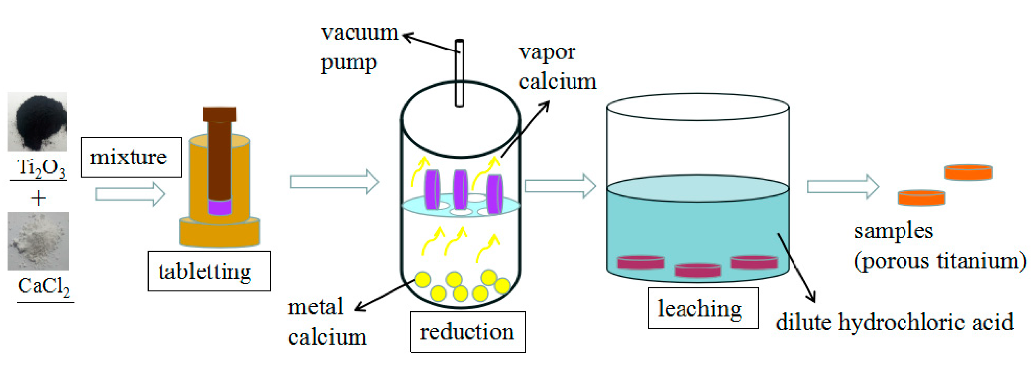
2.2. Experimental Procedures

2.2.1. Preparation of Samples before Reduction

A certain mix of Ti2O3/CaCl2 (wt.%) = 4:1 is formed into cylinder feeds of about Φ10 mm × 2 mm at a pressure of 4 MPa. The preform feeds are then put on a stainless steel screen plate in a stainless steel container. The stainless steel container containing no calcium metal is next heated in a well-type resistance furnace after the system pressure reaches 0.1 Pa. The heating rate is 5 K/min to 573 K and 10 K/min to 1125 K. When the temperature reaches 1125 K, the stainless steel container is removed from the furnace and the vacuum valve is immediately closed. At this point the samples before reduction are obtained.

2.2.2. Preparation of Reduction Samples

Mixed powders of Ti2O3 and CaCl2 with different mass ratios are milled and preformed into cylinder feeds of about Φ10 mm × 2 mm at a pressure of 4 MPa. These preform feeds are then transferred to a stainless steel screen plate in a stainless steel cylindrical container as shown in Figure 1. The stainless steel cylindrical container with reductant calcium in the bottom is next placed in a well-type resistance furnace. Calciothermic reduction is conducted below 0.1 Pa and the materials are heated constantly at different temperatures for assorted holding times. There is a stainless steel pipe as a condenser between the pump and reactor, so the calcium can condense before it enters the vacuum pump. After reduction, the reduction products are leached with dilute hydrochloric acid for 3 h and washed with deionized water and absolute alcohol three times. The heating rate in the experiment is 5 K/min to 573 K and 10 K/min to 1273 K. These experimental procedures are presented in Figure 1.

2.3. Characterization

The phase of reduction products was identified by X-ray diffraction (XRD) using a Rigaku (Tokyo, Japan) D/max-3B X-ray diffractometer equipped with graphite-monochromatized Cu Ka radiation. Scanning electron microscope (SEM) of S3400 N (Hitachi, Tokyo, Japan) was used to obsreve the particles and microstructure of the reduction products and its energy dispersive spectrometer (EDS) (Hitachi, Tokyo, Japan) was used to detect the element distribution of O, Ca, Cl and Ti.

3. Results and Discussion

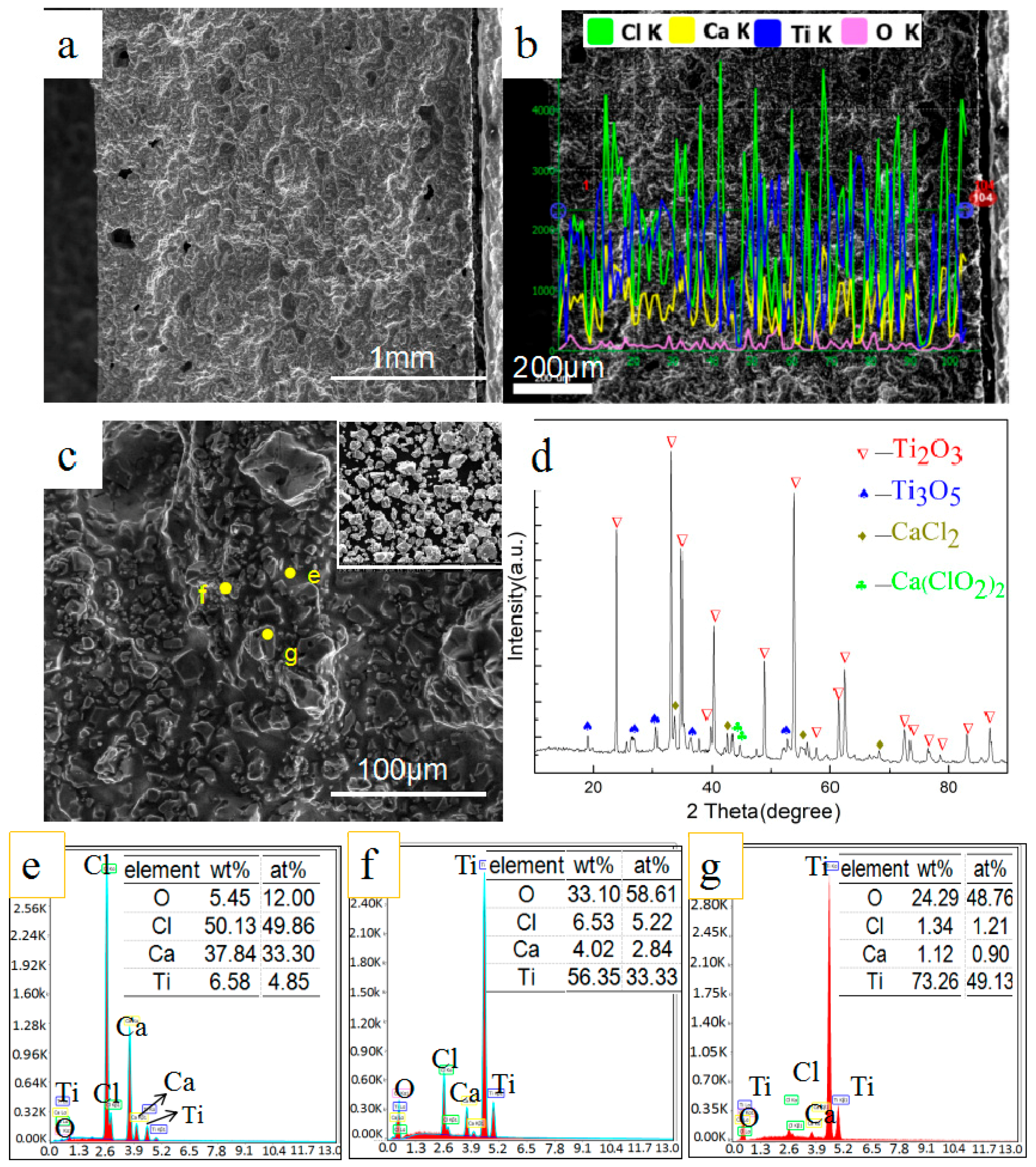
3.1. Phase and Microstructure of Preform Feeds before Reduction

According to the relationship between the saturated vapor pressure of calcium and temperature, metal calcium begins to volatilize once the temperature reaches 1125 K. This is consistent with the change of steam pressure in the experiment. It is understood that reduction has not occurred before the temperature reaches 1125 K because no calcium vapor comes into contact with the preform feeds. The weight loss ratio of the sintering products is 16.52%, higher than 9.86% calculated when all CaCl2 in the raw material was transformed to CaCl2·6H2O and all moisture was removed. Experiments conducted by Xu [20] also verify that calcium chloride begins to volatilize after 973 K. This result indicates calcium chloride volatilizes prior to calcium metal when they coexist in the same container. Figure 2 presents the scanning electron microscopy with energy dispersive spectroscopy (SEM-EDS) and X-ray diffraction (XRD) analysis of the cross section of sintered samples. It can be seen that the material preforms are structurally enhanced and stronger, and holes appear in the surface zone. The XRD patterns show a main phase of Ti2O3 and weak peaks of CaCl2 because of its relatively low content. A small amount of Ti3O5 and Ca(ClO2)2 is detected because the Ti2O3 is oxidized and CaCl2 absorb water and is dehydrated during heating. The Ti2O3 retains the shape of the original particles, and uniformly embeds in molten calcium chloride as shown in Figure 2c (the inset is particles of Ti2O3).

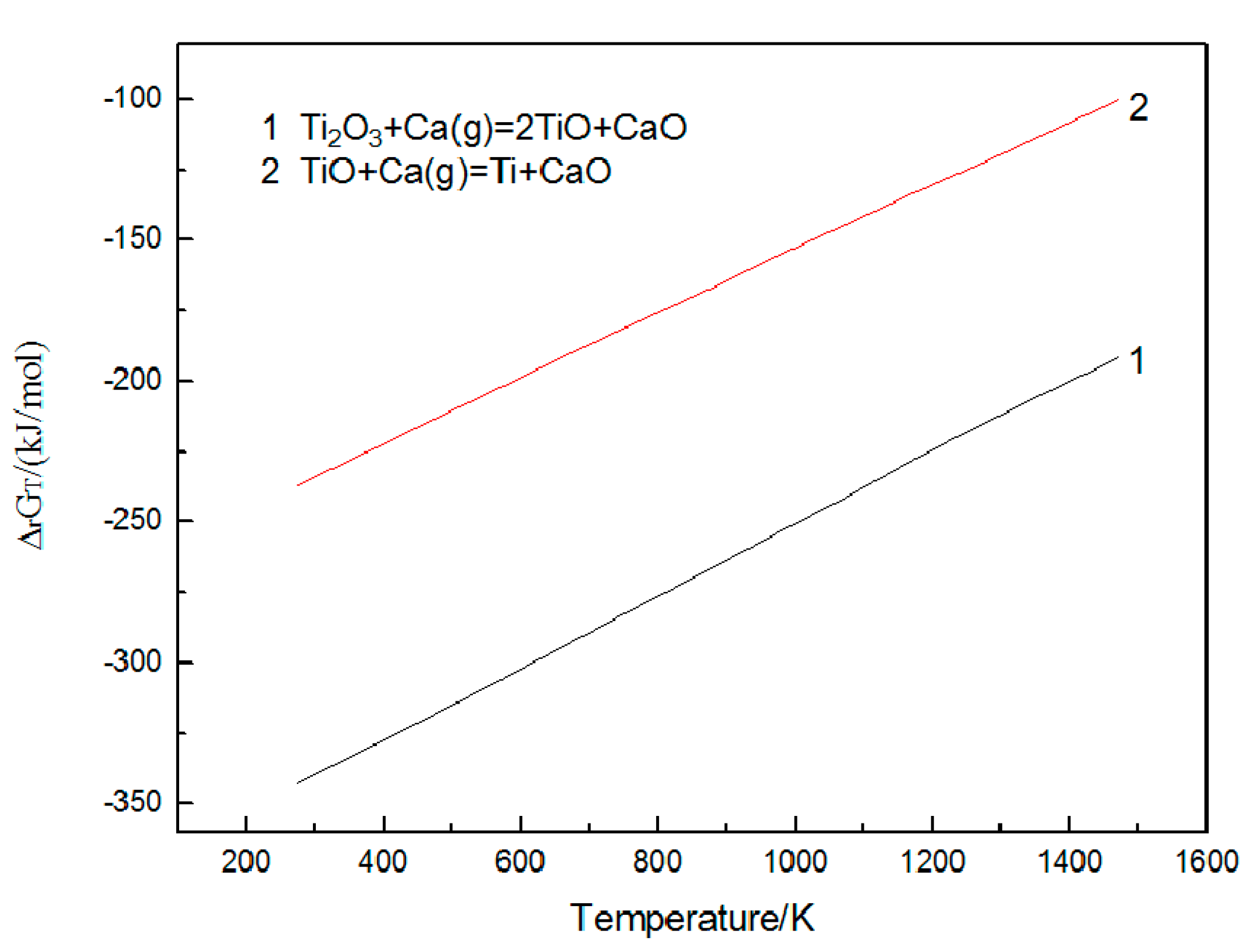
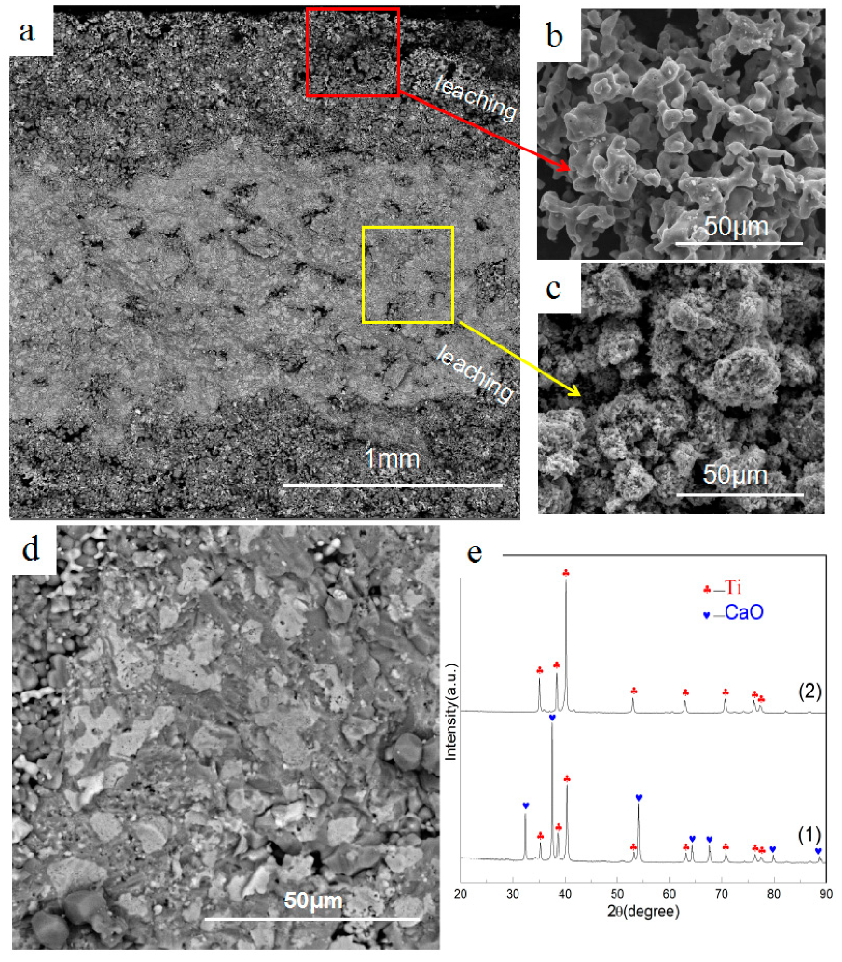
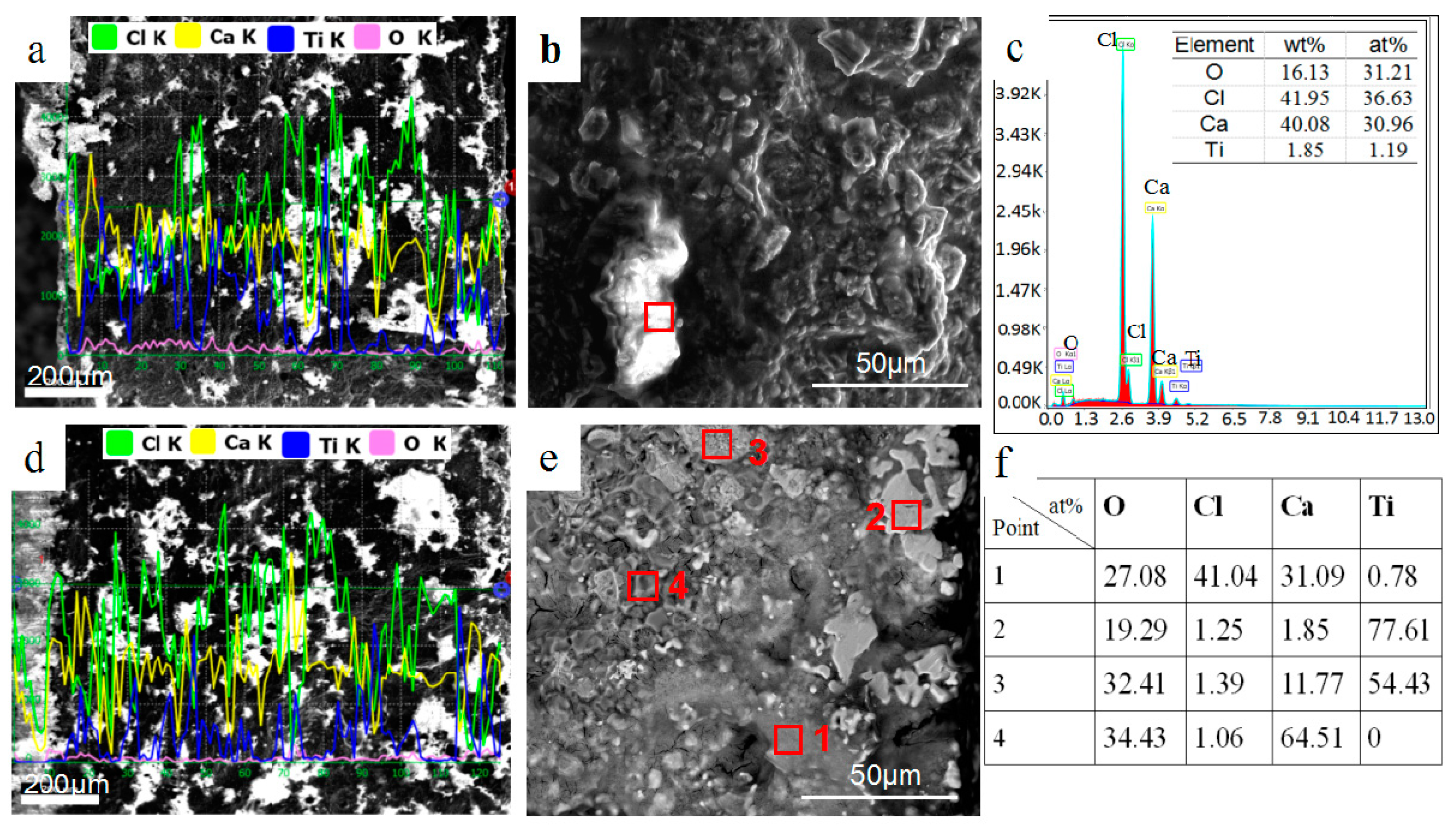
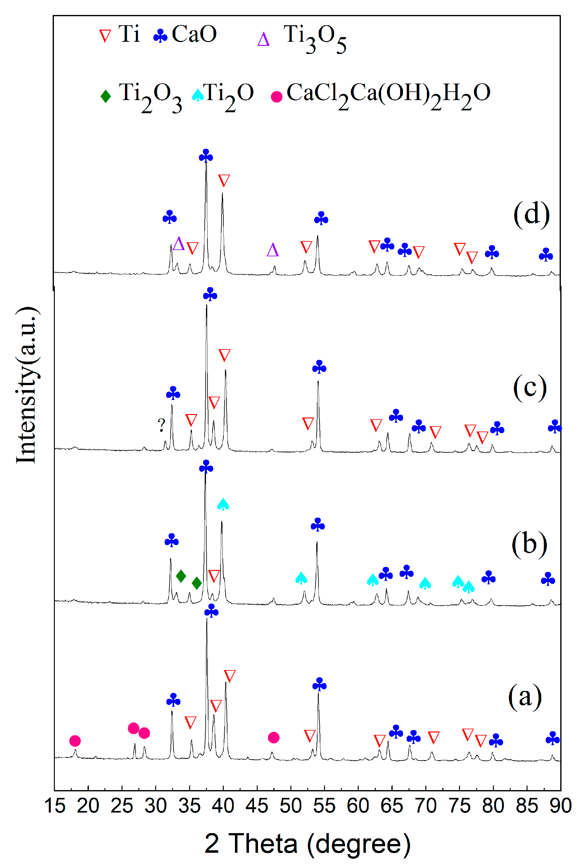
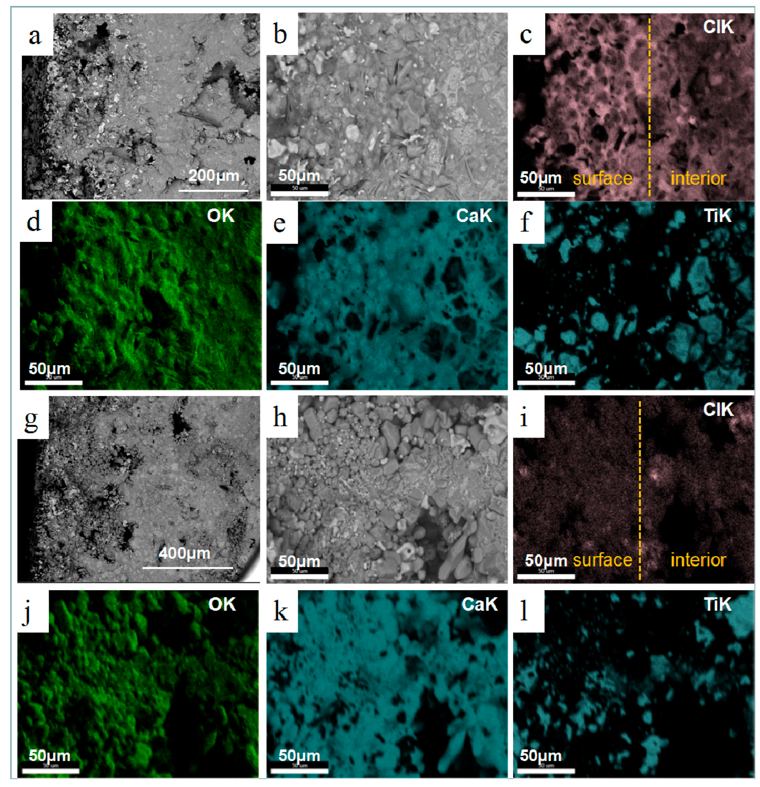
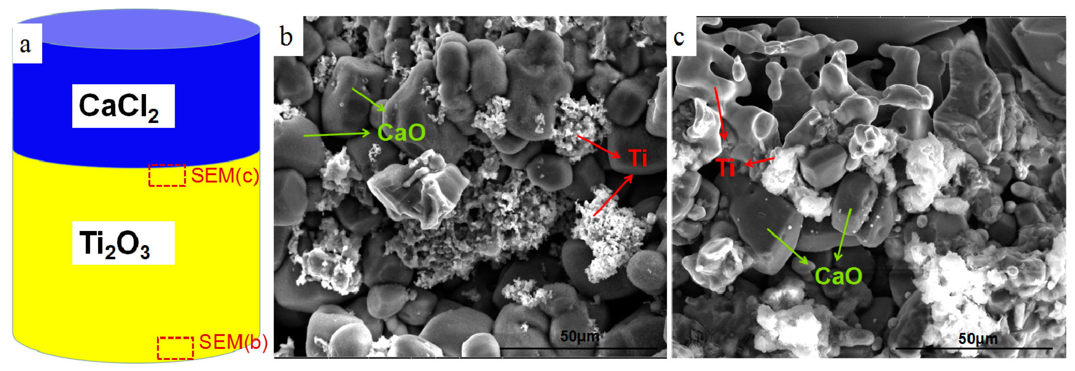
3.2. Effect of Calcium Chloride on Microstructure of Reduction Products

The reduction of Ti2O3 is considered step by step [16]: Ti2O3-TiO-Ti, and the Gibbs energy of these reactions is shown in Figure 3. The entire cross-section of reduction products after 4 h using the raw material with Ti2O3/CaCl2 (wt.%) = 4:1 is illustrated in Figure 4. Two distinct areas in the reduction sample are presented. Clear antler-shaped titanium particles and polyhedral CaO particles are distributed in the surface layer at about 0.5 mm depth, while there is a mixed zone of Ti and CaO particles in the compact interior of samples detected by XRD, as shown in Figure 4(e1). No definite chloride composites are present in reduction samples and more titanium particles are present in the surface layer than in the interior body solidly connected to each other. It is found that even with an extended holding time and larger samples (D = 20 mm; h = 2 mm/ h = 4 mm), two different areas still coexist in the reduction products. Metal titanium is obtained after leaching, detected by XRD as shown in Figure 4(e2). Figure 4b,c shows SEM images of the surface and the interior of the sample after leaching. Titanium particles in the surface area have a large size and smooth morphology, while in the interior they are small in size. Pores with varying sizes are formed in the surface area.
The behavior of calcium chloride and its effect on the microstructure of the cross section is investigated. Composition distribution of reduction products of different reduction temperature and time is also studied. With the temperature rising to 1173 K, CaCl2 accumulates on the surface and inside, as shown in Figure 5a. The bright areas in Figure 5a were identified as the aggregation of CaCl2 by EDS analysis as shown in Figure 5b,c. At this time, although metallic calcium begins to evaporate, no significant reduction area develops. In addition to the partial aggregation of calcium chloride, the overall morphology does not change significantly. When the temperature reaches 1273 K, the thickness of calcium chloride on the surface increases significantly and holes appear in the CaCl2 interior due to volatilization, as shown in Figure 5d. At this temperature, a large amount of calcium vapor comes into contact with the material layer and diffuses into the interior to initiate the reduction reaction. In molten calcium chloride at about 50 μm depth of surface area, dense and large-sized titanium particles and by-product calcium oxide particles form. In the interior, however, only titanium sponge takes shape, as shown in Figure 5e.
After reduction at 1273 K for 30 min, the morphology of the sections morph into two different parts which approach the morphology of the reduction product after 4 h. Figure 6a,b illustrates that the surface layer is completely reduced to titanium and the interior is in the process of being reduced because of the obvious Ti2O peaks and faint peaks of Ti and Ti2O3. The CaCl2Ca(OH)2H2O phase detected in the surface area is generated by water absorption of CaCl2 and CaO in the reduction sample. Figure 7a–f is the SEM images of the product cross sections. The internal titanium particles, which are not completely reduced, retain the morphology of Ti2O3 particles, while the titanium particles in the surface melt and transform into dense and large particles. Compared with the reduction products of 4 h, the products under this condition are regarded as transitional. In order to clearly present the distribution of calcium chloride and its relationship with other elements, the section is analyzed using elemental map-scanning. Results indicate that other elements uniformly distribute in general, but there is significantly higher chlorine content in the surface area where there are existing dense titanium particles. This is caused by the volatilization and diffusion of CaCl2 from inside to outside. It is known that titanium particles with the same morphology are obtained in the experiments of molten salt electrolysis of titanium dioxide. Kikuchi and his coworkers also investigated the morphology and size of titanium particles in calcium chloride molten salt [21], and in their experiments the titanium dioxide particles were reduced by metallic calcium in calcium chloride molten salt. The size of the metallic titanium increased with reduction time by sintering in CaCl2 molten salt at a high temperature (T = 1173 K). Therefore, in the process of calciothermic reduction of Ti2O3, the effect of molten CaCl2 salt is notable in the surface zone because of the enrichment of CaCl2, while in the interior the presence of much less calcium chloride barely affects the morphology and size of titanium particles. The reduction in the surface zone is similar to the experiments of Kikuchi. Compact Ti particles are generated because CaCl2 can significantly accelerate the aggregation and growth of metallic particles [22]. The SEM and map-scan images illustrating results when the reaction time was extended to 1 h, are presented in Figure 7g–l. In this condition, calcium chloride on the surface volatilizes and uniformly distributes across the entire section with less content, along with CaO particles that appear clear. Analysis by XRD shows that the products are mostly titanium and calcium oxide, while chlorinated compounds are not detected because of their low content, as shown in Figure 6c,d.

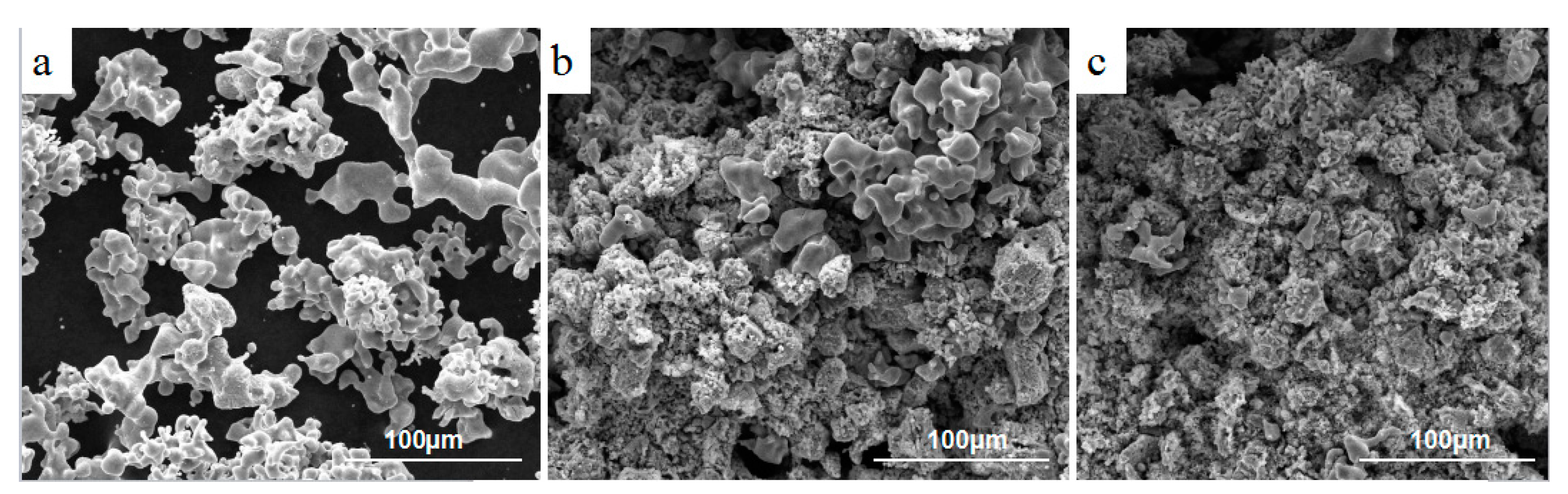
3.3. Effect of Calcium Chloride on the Size of Titanium Particles

The reason that different parts appear is that titanium particles have different morphologies and sizes. Through the above analysis, it is also found that calcium chloride plays a key role in the formation of different titanium particles. In order to further explore the effect of calcium chloride on the morphology and size of titanium particles, reduction products are dissolved by low content hydrochloric acid for 3 h and washed with deionized water and absolute alcohol three times; then, the products are dried in a vacuum at 373 K. When the content of calcium chloride in the raw material reaches Ti2O3/CaCl2 (wt.%) = 2:1, the porous block is not obtained because the titanium particles are not interconnected after leaching. When the raw material is Ti2O3/CaCl2 (wt.%) = 4:1 and 6:1, the complete porous titanium block is obtained and the shape of the leaching products are the same as after the reduction. The morphologies and sizes of the titanium particles are presented in Figure 8. Corresponding with the decrease of calcium chloride content in the raw materials, large titanium particles decrease significantly and small titanium particles, which merge together, increase. This process indicates that calcium chloride significantly promotes the agglomeration of titanium particles to grow. For materials with Ti2O3/CaCl2 (wt.%) = 2:1, a high content of calcium chloride advances the formation of dense and large size titanium particles in the interior.
Pure calcium chloride and Ti2O3 are designed in different layers in the raw materials, as shown in Figure 9a. The preformed feeds are reduced by the same conditions and were characterized by SEM, which can be seen in Figure 9b,c. The reduction on both sides with Ti2O3 is carried out, but not completely, indicating that the reaction rate for the calciothermic reduction of pure Ti2O3 is slow without mixed calcium chloride. The thickness of the reaction layer on one side of the calcium chloride is slightly larger than on the other side, also indicating that calcium chloride has a significant promoting effect on the reduction reaction. On the side with calcium chloride, the reduction products are large antler-shaped titanium particles, while on other side, the reduction products are small titanium particles. This confirms the effect of calcium chloride on the agglomeration of titanium particles.

4. Conclusions

The effect of CaCl2 on the calcium vapor reduction process of Ti2O3 was investigated in this paper. CaCl2 volatilizes prior to calcium metal in the container, and the main phases are still titanium and calcium chloride before Ca volatilizes. CaCl2 undergoes a notable transfer to the surface of the preform throughout the reduction, leading to a higher content of the compound in the surface area than in the interior. This distribution difference of CaCl2 in reduction preform causes the microstructure differences of reduction products. More CaCl2 causes the aggregation of Ti particles to form large Ti particles which are advantageous as they connect and form a more solid porous titanium structure. The presence of a small amount of CaCl2 in the interior also results in the coexistence of small Ti and CaO particles, forming a loose structure with uniform distribution. The porous titanium obtained by leaching the reduction product does not have enough structural strength; however, its structural strength needs to be vacuum sintered to strengthen. Meanwhile, further research is needed into how to control the structure and particles size.

Author Contributions

Conceptualization, B.X.; Methodology, G.Y. and B.X.; Formal Analysis, G.Y. and H.W.; Investigation, G.Y., F.W. and Z.W.; Data Curation, G.Y., Z.W. and B.X.; Writing-Original Draft Preparation, G.Y.; Writing-Review & Editing, B.X.; Supervision, B.X. and B.Y.; Project Administration, B.X.; Funding Acquisition, B.X.

Funding

This research was funded by [National Natural Science Foundation of China] grant number [51464023] and [51674129]; [Science and Technological Talent Cultivation Plan of Yunnan Province, China] grant number [2017HB009]; [Cultivating Plan Program for the Leader in Science and Technology of Yunnan Province] grant number [2014HA003]; [Program for Nonferrous Metals Vacuum Metallurgy Innovation Team of Ministry of Science and Technology] grant number [2014RA4018]; The APC was funded by [National Natural Science Foundation of China] grant number [51464023].

Acknowledgments

This work has been founded by the Fund of National Natural Science Foundation of China (grant number 51464023) and (grant number 51674129); Science and Technological Talent Cultivation Plan of Yunnan Province, China (grant number 2017HB009); the Cultivating Plan Program for the Leader in Science and Technology of Yunnan Province (grant number 2014HA003); the Program for Nonferrous Metals Vacuum Metallurgy Innovation Team of Ministry of Science and Technology (grant number 2014RA4018).

Conflicts of Interest

The authors declare no conflict of interest. The funders had no role in the design of the study; in the collection, analyses, or interpretation of data; in the writing of the manuscript, and in the decision to publish the results.

References

  1. Liu, P.S.; Liang, K.M. Review Functional materials of porous metals made by P/M, electroplating and some other techniques. J. Mater. Sci. 2001, 36, 5059–5072. [Google Scholar] [CrossRef]
  2. Kato, K.; Yamamoto, A.; Ochiai, S.; Daigo, Y.; Isobe, T.; Matano, S.; Omori, K. Cell Proliferation, Corrosion Resistance and Mechanical Properties of Novel Titanium Foam with Sheet Shape. Mater. Trans. 2012, 53, 724–732. [Google Scholar] [CrossRef] [Green Version]
  3. Siegkas, P.; Tagarielli, V.L.; Petrinic, N.; Lefebvre, P. The compressive response of a titanium foam at low and high strain rates. J. Mater. Sci. 2011, 46, 2741–2747. [Google Scholar] [CrossRef]
  4. De Vasconcellos, L.M.; Leite, D.D.; Nascimento, F.O.; de Vasconcellos, L.G.; Graca, M.L.; Carvalho, Y.R.; Cairo, C.A. Porous titanium for biomedical applications: an experimental study on rabbits. Med. Oral Patol. Oral Cir. Bucal 2010, 15, e407–e412. [Google Scholar] [CrossRef] [PubMed]
  5. He, G.; Liu, P.; Tan, Q. Porous titanium materials with entangled wire structure for load-bearing biomedical applications. J. Mech. Behav. Biomed. Mater. 2012, 5, 16–31. [Google Scholar] [CrossRef] [PubMed]
  6. Pattanayak, D.K.; Matsushita, T.; Takadama, H; Fukuda, A.; Takemoto, M.; Fujibayashi, S.; Sasaki, K.; Nishida, N.; Nakamura, T.; Kokubo1, T. Fabrication of Bioactive Porous Ti Metal with Structure Similar to Human Cancellous Bone by Selective Laser Melting. Bioceram. Dev. Appl. 2011, 1. [Google Scholar] [CrossRef]
  7. Shen, H.; Brinson, L.C. A numerical investigation of porous titanium as orthopedic implant material. Mech. Mater. 2011, 43, 420–430. [Google Scholar] [CrossRef]
  8. Esen, Z.; Şakir, B. Characterization of Ti-6Al-4V alloy foams synthesized by space holder technique. Mater. Sci. Eng. A 2011, 528, 3200–3209. [Google Scholar] [CrossRef]
  9. Oh, I.H.; Nomura, N.; Chiba, A.; Murayama, Y.; Masahashi, N.; Lee, B.T.; Hanada, S. Mechanical properties of porous titanium compacts prepared by powder sintering. Mater. Sci. Eng. C 2005, 25, 330–335. [Google Scholar]
  10. Xie, L.; Liao, X.; Yin, G.; Huang, Z.; Yan, D.; Yao, Y.; Liu, W.; Chen, X.; Gu, J. Structure, morphology and fibroblasts adhesion of surface-porous titanium via anodic oxidation. J. Mater. Sci. Mater. Med. 2010, 21, 259–266. [Google Scholar] [CrossRef] [PubMed]
  11. Ryan, G.E.; Pandit, A.S.; Apatsidis, D.P. Porous titanium scaffolds fabricated using a rapid prototyping and powder metallurgy technique. Biomaterials 2008, 29, 3625–3635. [Google Scholar] [CrossRef] [PubMed]
  12. Song, H.Y.; Kim, Y.H.; Chang, S.H.; Oh, I.H. Biocompatibility of Low Modulus Porous Titanium Implants Fabricated by Spark Plasma Sintering. Korean J. Mater. Res. 2007, 17, 107–114. [Google Scholar] [CrossRef]
  13. Sakamoto, Y.; Moriyama, S.; Endo, M.; Kawakami, Y. Mechanical Property of Porous Titanium Produced by Spark Plasma Sintering. Key Eng. Mater. 2008, 385–387, 637–640. [Google Scholar] [CrossRef]
  14. Watanabe, T. The Sintering Phenomenon of Titanium Powders—A Discussion. Int. J Powder Met. Powder Technol. 1976, 12, 209–214. [Google Scholar]
  15. Ahn, M.K.; Jo, I.H.; Koh, Y.H.; Kim, H.E. Production of highly porous titanium (Ti) scaffolds by vacuum-assisted foaming of titanium hydride (TiH2) suspension. Mater. Lett. 2014, 120, 228–231. [Google Scholar] [CrossRef]
  16. Wan, H.L.; Xu, B.Q.; Dai, Y.N.; Yang, B.; Liu, D.C. Preparation of titanium powders by calciothermic reduction of titanium dioxide. J. Cent. South Univ. Technol. 2012, 19, 2434–2439. [Google Scholar] [CrossRef]
  17. Jia, J.G.; Xu, B.Q.; Yang, B.; Wang, D.; Liu, D.C. Preparation of Titanium Powders from TiO2 by Calcium Vapor Reduction. JOM 2013, 65, 630–635. [Google Scholar] [CrossRef]
  18. Lei, X.; Xu, B.; Yang, G.; Shi, T.; Liu, D.; Yang, B. Direct calciothermic reduction of porous calcium titanate to porous titanium. Mater. Sci. Eng. C 2018, 91, 125–134. [Google Scholar] [CrossRef] [PubMed]
  19. Okabe, T.H.; Oda, T.; Mitsuda, Y. Titanium powder production by preform reduction process (PRP). J. Alloys Compd. 2004, 364, 156–163. [Google Scholar] [CrossRef]
  20. Xu, B.; Yang, B.; Jia, J.; Liu, D.; Xiong, H.; Deng, Y. Behavior of calcium chloride in reduction process of titanium dioxide by calcium vapor. J. Alloys Compd. 2013, 576, 208–214. [Google Scholar] [CrossRef]
  21. Kikuchi, T.; Yoshida, M.; Matsuura, S. Rapid reduction of titanium dioxide nano-particles by reduction with a calcium reductant. J. Phys. Chem. Solids 2014, 75, 1041–1048. [Google Scholar] [CrossRef] [Green Version]
  22. Dong, J.; Wei, Y.; Lu, C.; Zhou, S.; Li, B.; Ding, Z.; Wang, C.; Ma, B. Influence of Calcium Chloride Addition on Coal-Based Reduction Roasting of Low-Nickel Garnierite Ore. Mater. Trans. 2017, 58, 1161–1168. [Google Scholar] [CrossRef] [Green Version]
Figure 1. Schematic representation of the experiment.
Metals 08 00698 g001
Figure 2. Scanning electron microscopy with energy dispersive spectroscopy (SEM-EDS) and X-ray diffraction (XRD) analysis of cross section of sintered sample at 1125 K: (a) overall morphology; (b) line-scan image; (c) local morphology; (d) XRD pattern; (eg) EDS results of (c).
Metals 08 00698 g002
Figure 3. Relationships between Gibbs energy changes and temperature.
Metals 08 00698 g003
Figure 4. The SEM images and XRD pattern of cross section of reduced products: (a) the cross section of reduced products; (b,c) the samples after leaching; (d) The middle area of cross section; (e1) the XRD pattern of (d); (e2) the XRD pattern of the leaching sample.
Metals 08 00698 g004
Figure 5. The cross section and EDS analysis of reduction products with different temperature: (a) line-scan image of reduction product at 1173 K; (b) microstructure of reduction product at 1173 K; (c) EDS result of (b); (d) line-scan image of reduction product at 1273 K; (e) microstructure of reduction product at 1273 K; (f) EDS results of (e).
Metals 08 00698 g005
Figure 6. XRD analysis of reduction products with different time and regions at 1273 K: (a) surface of reduction product for 30 min; (b) interior of reduction product for 30 min; (c) surface of reduction product for 1 h; (d) interior of reduction products for 1 h.
Metals 08 00698 g006
Figure 7. SEM images and corresponding map-scan of products with different reduction time at 1273 K: (a,b) reduction product for 30 min; (cf) distribution of element of (b); (g,h) reduction product for 1 h; (il) distribution of element of (h).
Metals 08 00698 g007
Figure 8. Leaching samples with different content of CaCl2 in raw material: (a) Ti2O3/CaCl2 (wt.%) = 2:1; (b) Ti2O3/CaCl2 (wt.%) = 4:1; (c) Ti2O3/CaCl2 (wt.%) = 6:1.
Metals 08 00698 g008
Figure 9. Schematic diagram of raw materials; (b,c) SEM images of reduction products.
Metals 08 00698 g009
Table 1. Materials used in experiments.
MaterialFormPurity or Content/%Producer
Ti2O3Powder>99Aladdin Industrial Co., Ltd., Shanghai, China
Ca particlesGranular>98Aladdin Industrial Co., Ltd., Shanghai, China
CaCl2Powder>99Sinopharm Chemical Reagent Co., Ltd., Shanghai, China
HClAqueous3.5 aChuandong Chemical Group Co., Ltd., Chongqing, China
a Mass concentration of solution.

