Article

Microstructure and Performance of a Three-Layered Al/7075–B4C/Al Composite Prepared by Semi Continuous Casting and Hot Rolling

1
Key Laboratory of Solidification Control and Digital Preparation Technology (Liaoning Province), School of Materials Science and Engineering, Dalian University of Technology, Dalian 116024, China
2
School of Mechanical and Power Engineering, Dalian Ocean University, Dalian 116023, China
3
Engineering Institute, Bohai University, Jinzhou 121001, China
4
State Key Laboratory of Metal Material for Marine Equipment and Application, Anshan 114000, China
*
Authors to whom correspondence should be addressed.
Metals 2018, 8(8), 600; https://doi.org/10.3390/met8080600
Submission received: 26 June 2018 / Revised: 25 July 2018 / Accepted: 30 July 2018 / Published: 1 August 2018

Abstract

:
A three-layered composite material, consisting of an Al outer layer and a 7075-10 wt % B4C inner layer, was fabricated by semi-continuous casting and following a hot rolling process. The composite exhibits a clear layered structure with a good interfacial bond between layers. In the sessile drop experiment, the Al alloy melt dropped on the 7075-B4C composite at 650 °C, with the contact angle decreasing from 105° to 25° in 50 s, indicating that the infiltration and spreading both played important roles in the wetting process. In the inner layer, the reinforced B4C particles were distributed uniformly in the 7075 alloy matrix, and enhanced the average hardness of the inner layer to 163.4 HV, compared to that of the outer layer at 32.8 HV. The composite plate of 20 mm obtained the compression strength of 152 MPa. The electron probe microanalysis (EPMA) line scanning result showed that no harmful reaction or element diffusion occurred between B4C and the surrounding 7075 matrix. The B4C particles remained mechanically bonded into the matrix, and significantly reduced the bullet speed during the projectile impact test.

1. Introduction

Layered structure materials consisting of two or more metals are now widely used in manufacturing, military, and aerospace industries. These multi-layered composites always present a better performance than the single-layer ones, due to the combination of different characteristics [1]. New kinds of functional materials can be acquired by designing structures layered in novel ways. Therefore, such materials are considered to contribute new levels of improvement to the traditional materials industry, and to have broad application prospects.
The boron carbide-reinforced aluminum layered composite (BRALC), which is made of one metal ceramics inner layer and Al/Al-alloy outer layers, possesses a soft–hard–soft structure. This “sandwich” material offers better protective performance and a lower weight, and is considered to be a candidate to replace the traditional high-hardness armor material [2,3,4,5,6]. The boron carbide (B4C) reinforcement phase is well-known, not only for its advantageous high thermal stability and wear resistance, but also for its exceptional hardness. The addition of B4C particles can significantly improve the strength and hardness of the composite [7,8,9,10]. Due to its good neutron absorptivity without forming long-lived radionuclides, a BRALC plate may be also used as protection cover for the transportation of nuclear material. On the other hand, Al and its alloys are widely used as matrices for composites, owing to the low density and good composability of Al. In the BRALC plate, the outer Al layers provide enough support, as well as a better weld ability.
However, there are some technological problems during the fabrication of BRALC material. For example, it is difficult to achieve both the high proportion of B4C in a composite and an industrial scale at the same time. Moreover, B4C reacts with Al when the temperature is higher than 450 °C (even though Al is in the solid state below 660 °C), leading to the first formation of ternary carbide Al4BC [11]. When the temperature increases, especially when Al is in a liquid state, the reaction rate increases rapidly. The reaction products are Al3BC and AlB2 when the temperature range is between 600 and 870 °C [12,13]. Such reactions are proved to degrade the interface strength between the reinforcement and the matrix, which changes the predominant damage mode from particle fracture to interface decohesion during the fracture process. Thus, it is of great importance to avoid these reactions, which is a constantly difficult problem for some conventional techniques. Many methods, such as pressure-less infiltration [14], casting [15,16], and powder metallurgy [17,18,19], are used for the production of B4C-Al composites. Among these methods, powder metallurgy is the most used technology [20,21,22], but its low efficiency and high cost severely limit its wide application. In comparison, the casting method can achieve efficient production and low cost, especially for the production of large-sized ingots. However, some technological problems, such as particle agglomeration and excessive reaction between B4C and Al, need to be resolved.
The objective of this work is to provide a new method of semi-continuous casting and hot rolling to prepare a layered metal ceramic composite, which achieves both high proportion and uniform distribution of reinforcement particles in an industrial-scale composite. After the optimization of parameters, the improved BRALC plate fabricated by this method may meet the requirements of armor material.
In the present study, a sessile drop experiment was conducted, first to verify the bonding conditions of different layers during the casting process. Then, a three-layered composite material, consisting of two Al layers and a 7075-10 wt % B4C inner layer, was produced by a combination of an Al melt and 7075-B4C powder mixture in a semi-continuous casting method. The further hot rolling process was carried out at 450 °C to obtain a required thickness plate, and to avoid adverse reactions. The distribution of B4C particles in the inner layer and the conformations of interface between the different layers were characterized by means of optical microscope (OM), Scanning Electron Microscope (SEM) and electron probe microanalyzer (EPMA). The hardness distribution, compression strength, and bullet impact tests of the BRALC plate were carried out. The bulletproof mechanism (i.e., the reduction of bullet speed) of the BRALC plate was also discussed.

2. Experimental Procedure

Commercially pure aluminium (CPAl, 99.7 wt %) was used as the starting material for the outer layer, while the analytically pure 7075 aluminum alloy powder (about 35 µm) and B4C powder (about 72 µm) were used for the inner layer. The B4C particles were supplied by the Dalian Jinma Boron Technology Group (Liaoning, China). Table 1 lists the chemical composition of the 7075 alloy powder used in this study. During the preprocessing, the 7075 powder and B4C powder were treated in an planetary ball miller (SFM-1, Pinchuang technology Co., Ltd, Tianjin, China) at a speed of 300 rpm for 3 h, with a planetary-disk rotation speed of 510 rpm. The ball-to-poder weight ratio was 1:1. Since the mass fraction of B4C in the inner layer is 10% in this study, the mass ratio of 7075 powder to B4C powder in the mixture was 9:1.
The wettability between the Al liquid and 7075-B4C composite was studied by a sessile drop experiment, the equipment of which is shown in Figure 1a. The high temperature contact angle measurement equipment consisted of a dropping pipette, sample stage, high-speed camera, and vacuum and heating systems. During the test, the dropping alloy was heated together with the substrate in the furnace. In order to prevent a meltdown of the 7075-B4C substrate, the Al-10% Si alloy, the experimental temperature of which can be set lower to 650 °C, was used as a droplet. It was placed in the dropping pipette in the form of a small piece. During another part of the experiment, 7075 and B4C powders with a mass ratio of 9:1 were made into a substrate by a hot pressing process. This sample was pressed with 80 MPa for 30 s and kept at 450 °C for 30 min. After grinding, polishing, and ultrasonic cleaning, this 7075-10% B4C substrate was cut into a size of 16 mm × 16 mm × 4 mm, and then placed on the sample stage. When starting an experiment, the Al-10% Si alloy was melted in the dropping pipette at 650 °C under a vacuum (10−7 bar). Moving with the dropping pipette over the substrate, the Al-10% Si melt got attached to the substrate. After the droplet dropped onto the surface, the pipette moved away rapidly, leaving the droplet and the substrate in sight of the observation window. This moment was set as the initial time. The images obtained by the high-speed camera were vectorized by axisymmetric drop shape analysis (ADSA) and sessile drop device (SESDROPD 2.30, KINO, New York, NY, USA) software.
The wetting occurred as soon as the droplet made contact with the substrate, as shown in Figure 1b. θ is the contacting angle, used to characterize the wettability between the Al-Si liquid and the 7075-B4C composite. The contacting angle θ, the height h and the diameter d of the droplet can be acquired from the in-situ observation images.
After the sessile drop experiment, the combination of a liquid metal and ceramic-metal powder was chosen as a feasible way to obtain a metallurgical bond. Based on this, a semi continuous casting (see in Figure 2a) was carried out in order to achieve a metallurgical ingot with CPAl and 7075-B4C layers. The equipment consisted of pressured powder mixture auto-feeding module, Ar gas protection system, smelting and pouring module, inner and outer mold (crystallizer) with thermal insulation or cooling, and drawing drive module. It is worth noting that there was thermal insulation material on the surface of the inner mold at the melt side to support the designed bond of the liquid CPAl and 7075-B4C powder mixture at their interface, as shown in Figure 2b.
During the semi-continuous casting process, the mixed 7075-B4C powder was poured into the inner crystallizer under a protection atmosphere (Ar gas), and went downwards under pressure. Meanwhile, the CPAl was melted in the resistance furnace at 780 °C, and poured into the outer crystallizer at 740 °C through the insulated launder. When the CPAl melt got into the mold, the outer surface soon solidified under the influence of cooling water. At the same time, the inner surface of the CPAl melt stayed liquid until getting in touch with the 7075-B4C powders, since the inner mold was surrounded by thermal insulation material. In this case, the CPAl melt would directly infiltrate into the surface layer of the 7075-B4C mixture to achieve a stable bond. With the pulling out by drawing drive, the ingot was cooled rapidly under the second cooling water.
Figure 2c presents the ingot with a size of 440 mm × 230 mm × 120 mm (length, width, thickness) obtained by the semi-continuous casting. After easy surface pretreatment, hot rolling process was conducted at 450 °C by a twin-rolling machine, as shown in Figure 2d. A thinner BRALC plate was fabricated with a reduction ratio of ≤15% in each pass. This procedure was repeated up to 10 times in order to get the final BRALC plate with a thickness 20 mm. The size of the plate (in Figure 2d) obtained after hot rolling was 2150 mm × 280 mm × 20 mm (length, width, thickness). The BRALC plate was further rolled to an ultimate thickness of 3 mm, as shown in Figure 2e. The layered structure would no longer exist if the thickness were less than 3 mm, since the outer Al layer would not be enough to encompass the inner layer. The edge cracking also easily took place under this condition. Finally, the sample with 20 mm thickness was cut into pieces of appropriate size for further analysis.
The phase composition, microstructure, element distribution, compression, and hardness performance were investigated using SEM (supra55, Zeiss, Jena, Germany), EPMA (JXA-8530F Plus; JEOL, Tokyo, Japan), compression testing (DNS100; Changchun Research institute for Mechanical Science Co, Ltd., Changchun, China) and Vickers hardness testing (THVS-3000, Timetester Co, Ltd., Beijing, China), respectively. The Vickers hardness (HV) test was performed by a 10 mm steel ball, with a 500 kg load and 15 s dwell time. The compression and hardness tests were performed in accordance with the National Standards of People’s Republic of China GB/T7314-2005 and GB/T231.2-2002, respectively. The bullet impact test was carried out according to Chinese Military Specifications GJB59.18-88, the schematic diagram of which is shown in Figure 3. A 7.62 mm armour-piercing bullet was shot from a test gun, went through a pair of speed sensors, and then hit the 20 mm BRALC plate. Since the target material was pierced by the high speed bullet, a thick piece of 7A52-Al alloy plate was placed at the back to absorb the impact and energy of the bullet. In order to avoid errors, two pieces of layered composite plates fabricated under the same process were used for the bullet impact test. Each piece was shot twice by 7.62 mm bullets.

3. Results and Discussion

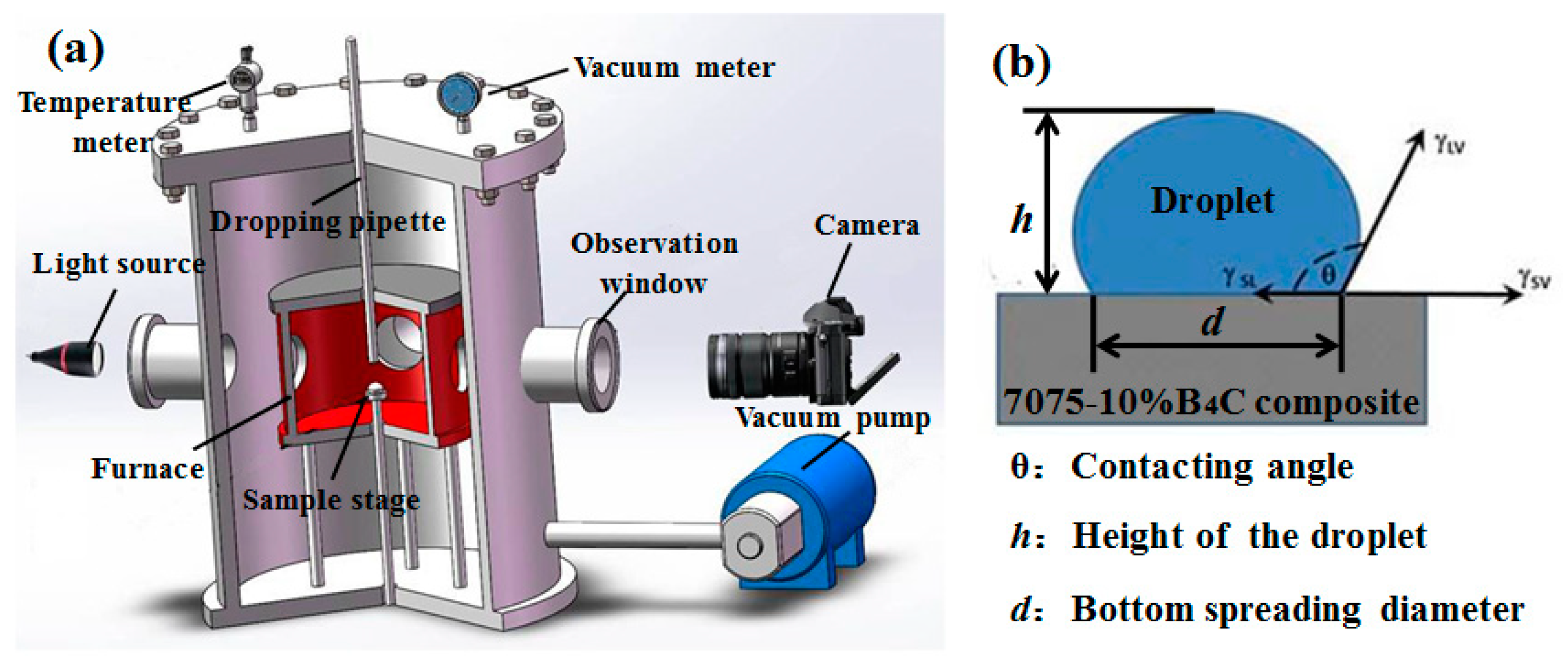
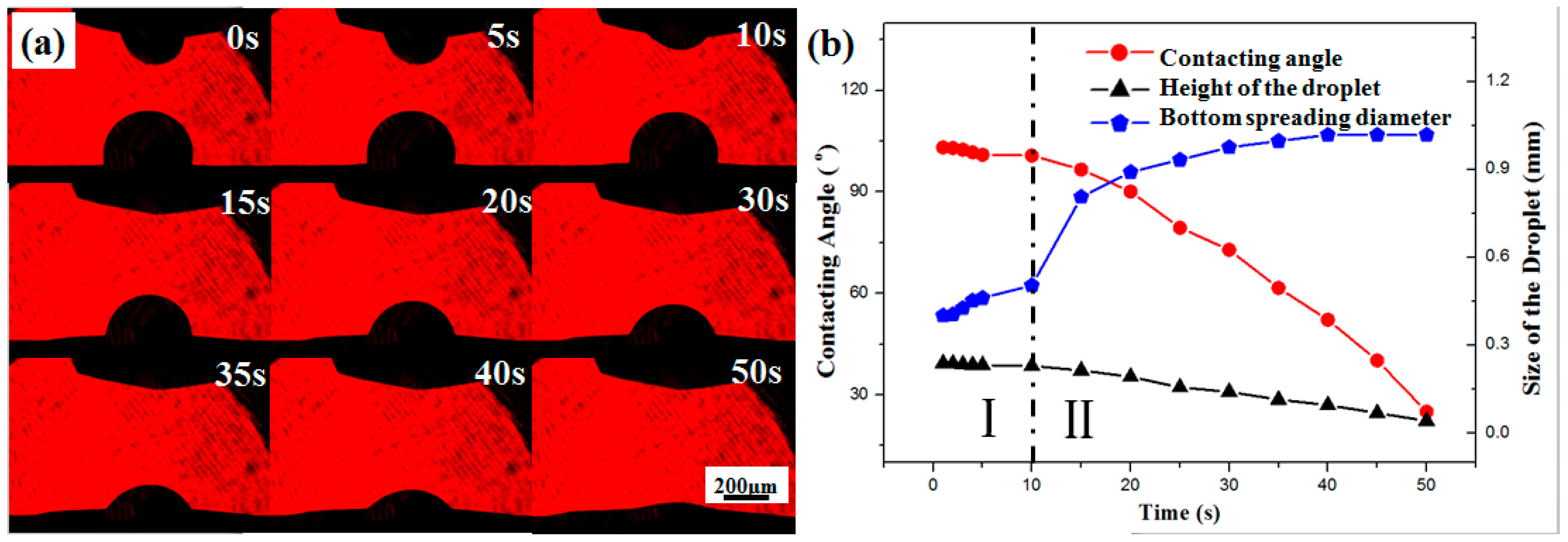
3.1. Wetting Behavior Between the Al Alloy Liquid and 7075-B4C Composite

Figure 4a reveals the infiltration and spreading process of the Al-Si alloy melt onto the 7075-B4C substrate. The time dependency of the contact angles and droplet size (including the top and bottom diameter) are summarized in Figure 4b. It can be clearly observed that the wetting process between the Al-Si melt and 7075-B4C substrate can be divided into two stages.
During the first 10 s period, the contact angle decreased from an initial 103° to approximately 100°. There was no obvious change of droplet shape from 0–10 s on the photographs. During the second stage (10–40 s), the contact angle decreased rapidly from l00° to 25°. The spreading process observed from the photographs was accelerated from 10 s to 50 s. When the contact angle was reduced close to 90°, the droplet rapidly spread on the surface of the substrate, which in turn promoted the wetting process. The height of the droplet also decreased obviously due to the spreading process. The base diameter had a significant increase from 0.512 mm to 1.018 mm, indicating that the liquid spreading played an important role during this period.
Wettability is generally defined as the ability of a liquid to spread on a solid surface, and represents the extent of intimate contact between the liquid and a solid. In this work, since the 7075-B4C substrate was made of powders via a hot pressing process, it possessed a less dense structure than one achieved by the casting method. The diffusion of the Al-Si liquid into the substrate cannot be ignored under this condition. The driving force for the wetting process is affected by two factors: the infiltration of liquid into the substrate and the spread of liquid on the surface of the substrate. In the initial stage, the infiltration here played a leading role, while the progress of the spread of liquid was very slow. On the one hand, the spread is highly dependent on the surface tension of the liquid at the interface. As shown in Figure 1b, the spread occurs only if the solid–vapor interface is replaced by a liquid–solid and liquid–vapor interface, with a reduction of free energy of the system. The initial contacting angle between the Al-Si liquid and the 7075-B4C substrate was 103°, and kept nearly invariable during Stage I, indicating a relatively high surface tension, as well as a high solid–liquid interface energy. On the other hand, the oxide layer at the surface created a resistance to the penetration of the Al-Si melt to the 7075-B4C substrate. Although the Al-Si ingot was melted under a vacuum condition, it was very difficult to avoid the formation of an oxide layer [23]. The surface of the Al-Si ingot transformed into the oxide layer of the liquid during the melting process. When the droplet was squeezed out of the pipette, the continuous oxide skin would be broken up, decreasing the amount of oxide at the interface between the liquid and the substrate. However, some oxide layer remained on the surface, leading to the occurrence of non-wetting in the first stage. It also explains the slow reduction of the contact angle, as well as the minor variation of the droplet height and bottom spreading diameter.
The infiltration of liquid into the substrate went slowly, but it caused the decrease of the contact angle. The bonding force between droplet and substrate, i.e., the work of adhesion therefore increased [24,25], resulting in an improvement of the wetting process between the liquid and solid surface. In addition, when infiltrating the 7075-B4C substrate, the droplet surface near their interface is destroyed. Hence, the liquid spreading process was promoted and accelerated in the second stage, which was observed as a significant change of the spreading diameter.
To summarize the sessile drop experiment, the wetting process between the Al-Si melt and 7075-B4C substrate is divided into two stages. Both the infiltration of liquid into the substrate and the spread of liquid on the surface played important roles during these two respective stages. Above all, the sessile drop experiment had demonstrated that the combination of a liquid Al and 7075-B4C mixture can be regarded as a feasible way to fabricate a BRALC ingot.

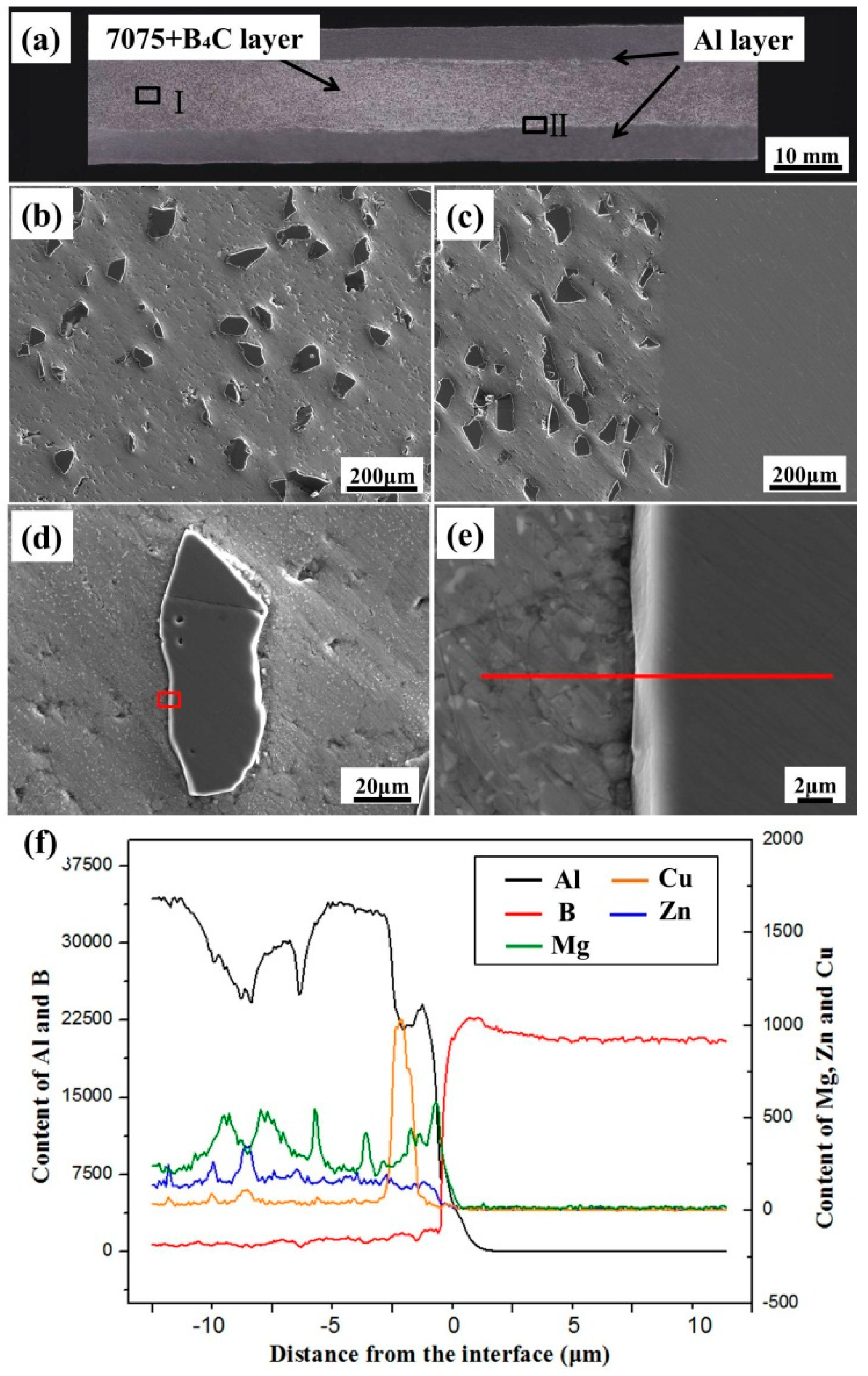
3.2. Microstructure of the Boron Carbide-Reinforced Aluminum Layered Composite Plate

Based on the result of the sessile drop experiment, a BRALC plate with 20 mm thickness was prepared by semi-continuous casting and a subsequent hot rolling process. Figure 5a–c presents the plate’s cross-sectional macrostructure and high magnification microstructures, at different regions. It is clear from Figure 5a that the composite has a layered structure consisting of two outer CPAl layers and one inner 7075-B4C layer, with a straight interface between them. The marked regions I and II are magnified in Figure 5b,c in order to observe the microstructures of the inner layer and the interface. Figure 5b indicates that B4C particles (in dark contrast) are uniformly distributed within the matrix without obvious segregations. The 7075 powders transformed into a matrix during the hot rolling process, and wrapped the B4C particles tightly. The interfacial microstructure between the outer CPAl layer and inner 7075-B4C layer is shown in Figure 5c. The straight interface, as well as good bonding between different layers, was obtained due to the similarity of the Al-based matrix. In addition, there are no cavities or cracks near the interfacial region, suggesting that the experimental parameters of both semi-continuous casting and the hot rolling process were adjusted appropriately.
Figure 5d displays a magnified morphology of one optional B4C particle from inner layer. Since there was a significant difference of hardness between the 7075 matrix and B4C particle reinforcement, the Al-based matrix was easier to wear off during the grinding and polishing process, leading to a height difference in appearance. The marked region is further magnified and shown in Figure 5e. The nano-scaled precipitated phase (in a light color) could be observed at the 7075 matrix side. The line scanning was carried out at the interface following the red line, as marked, and the result in Figure 5f reveals that the content of both Al (black line) and B (red line) had sharp changes near the interface, with an approximately 2 μm transition region. The obvious content variation of other elements (Zn, Mg, and Cu) was also observed near the interface. On the 7075 side, Al, Zn, Mg, and Cu were detected, with slight content fluctuations due to the presence of a precipitated phase. While on the B4C side, these metallic elements were not detected.
From both the morphological and line-scanning analysis, it is demonstrated that there is a good mechanical bond between B4C and Al without excess reactions or intermetallic compound reaction products. As mentioned above, the reaction between B4C and Al starts at about 450 °C with the formation of A14BC. With increasing temperatures, the products transform into Al3BC and AlB2. All of these phases tend to form large clusters of grains, resulting in lower strength and worse interfacial properties. In order to avoid the occurrence of these reactions, the hot rolling temperature in this work was processed at 450 °C. As a consequence, hardly any carbide or diboride was formed at the interface between B4C and Al.

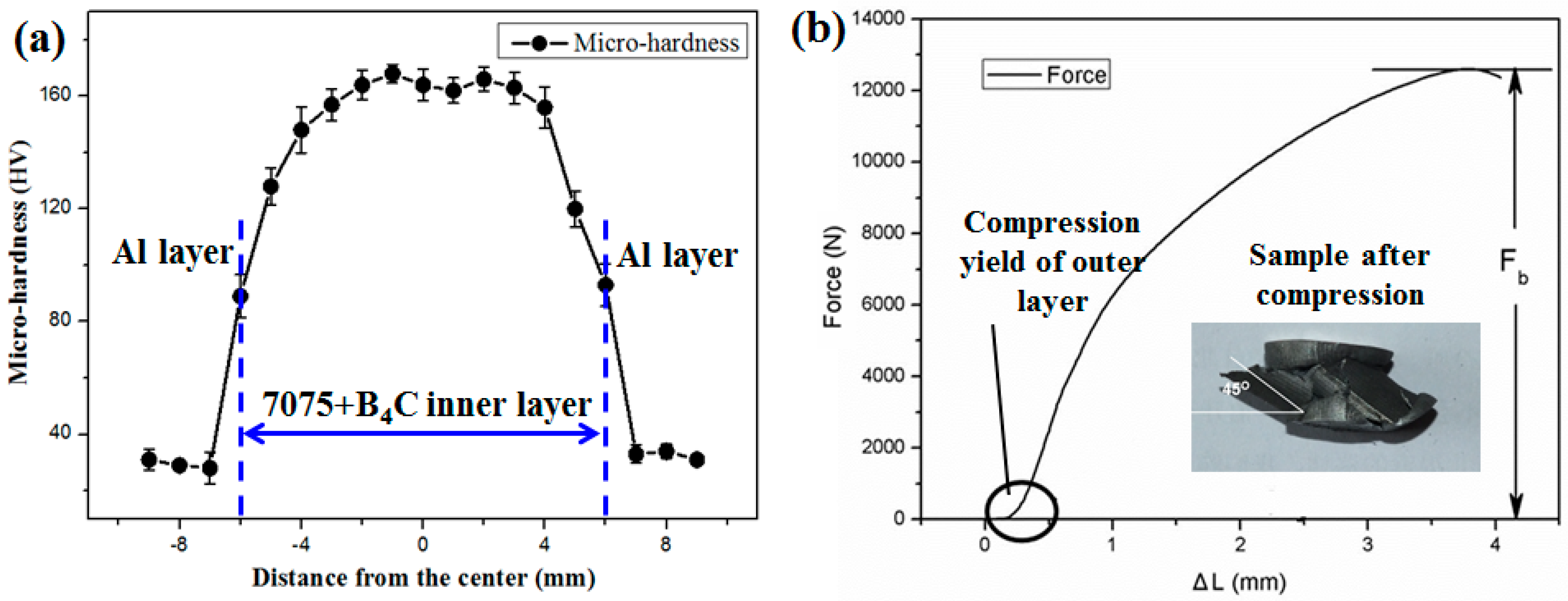
3.3. Mechanical Properties Tests

In order to verify the dissimilarity of properties for different layers, the Vickers hardness test was conducted along the central line, perpendicular to the interface. The result is presented in Figure 6a. The highest Vickers hardness, at 163.4 HV, corresponds to the 7075-B4C layer, while the outer layer possessed much lower hardness, at 32.8 HV. The sharp increase in the hardness value of the inner layer indicated that the addition of B4C particles into the 7075 matrix obviously improved the hardness value. The BRALC exhibited a clear “sandwich” structure (i.e., a soft–hard–soft layered structure).
The compression specimen and compression curve are shown in Figure 6b. The compression strength of the 20 mm BRALC sample was 152 MPa. As it is marked on the curve, the yield of the outer CPAl layer happened at the very beginning of the compression test. Due to the plasticity and lower strength, the deformation firstly occurred in the outer CPAl layer. No further remarkable yield occurred during the test. The plasticity of the 7075-B4C composite layer was not as high as that of the CPAl, therefore no remarkable compression yield was observed. The BRALC plate revealed good compression property.

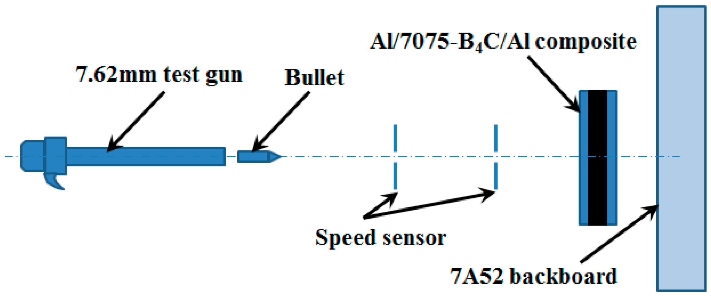
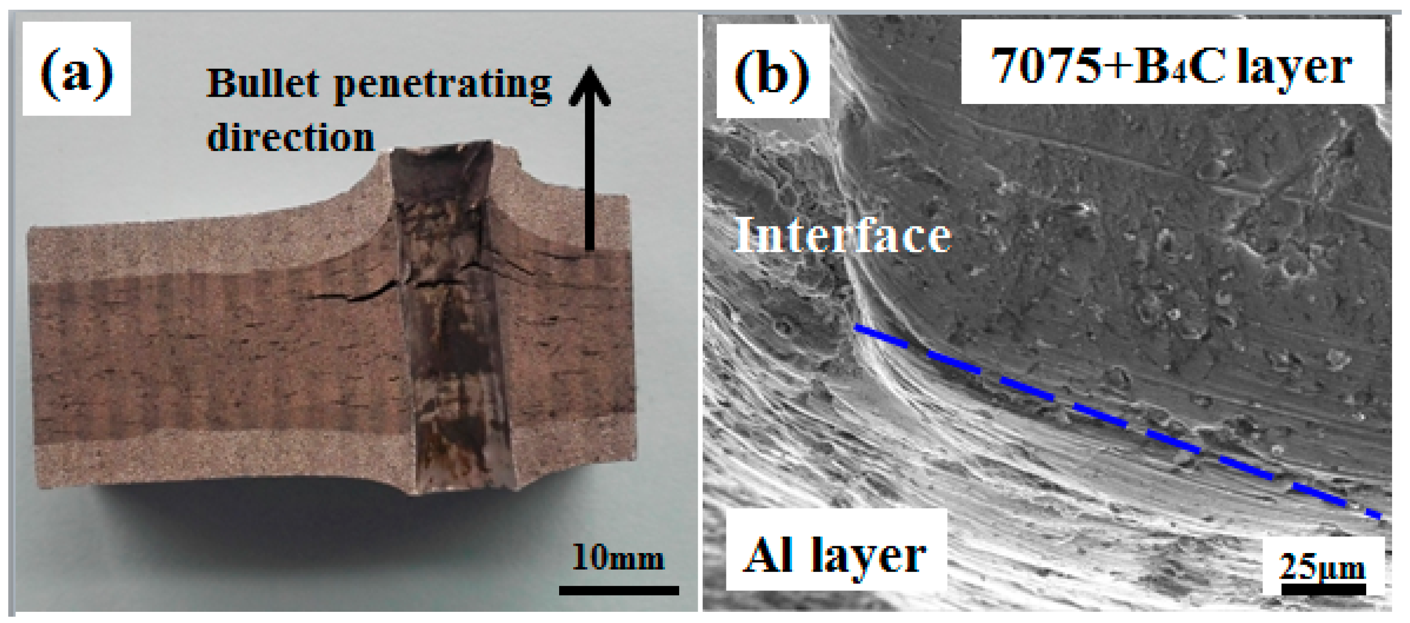
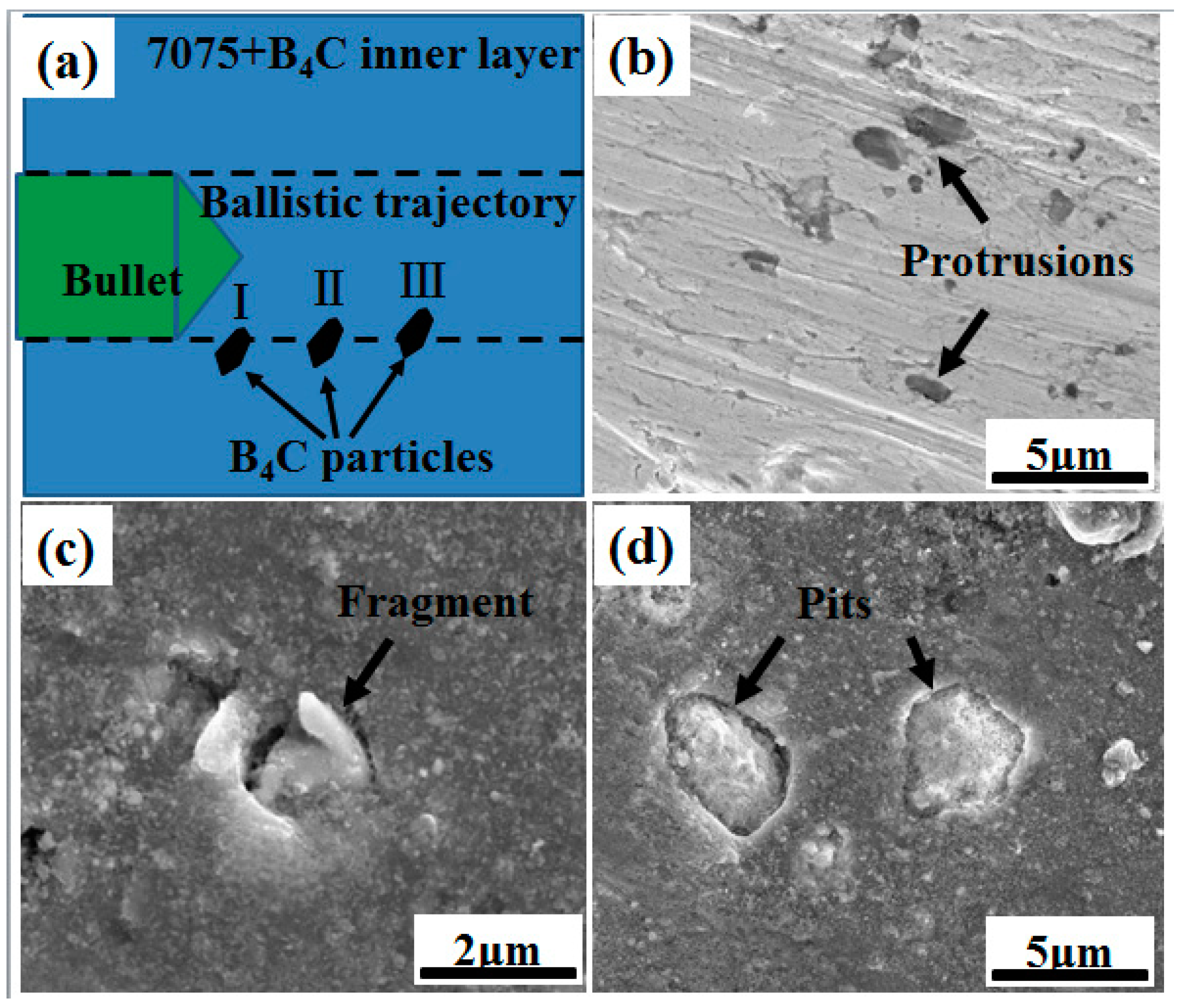
3.4. Bullet Impact Test

In order to test the protection performance of the BRALC plate, the bullet impact experiment was carried out. The cross-section of the bullet crater through the BRALC plate is shown in Figure 7a. Although the BRALC plate was perforated, the bullet speed was significantly reduced from 809.3 m/s to 327.84 m/s after passing through it.
When the bullet went through the first CPAl layer, which was designed to absorb the energy, a part of the impact energy was absorbed by the CPAl’s deformation layer. The deformation and subsequent destruction of outer layer can be observed from the crater picture. This process is referred as “shock absorbing”. As the bullet continued to penetrate into the inner layer, the hard 7075-B4C layer significantly reduced the strength of bullet impact. However, since the metal ceramic always possesses high hardness and brittleness, but lower plasticity, the bullet’s penetration easily resulted in fragmentation when a large deformation in the layer occurred. For the BRALC plate, the CPAl backing layer could absorb the kinetic energy from both the bullet and the inner layer, preventing the inner 7075-B4C layer from tensile failure and promoting more severe projectile erosion. During the bullet penetration process, the 7075-B4C layer was deformed, together with the CPAl backing layer. In this case, a large plastic deformation of these two layers was observed in Figure 7a. There were no macroscopic cracks at the layers’ interface, indicating that a stable interfacial bonding strength was obtained between the different layers. In the interior part of 7075-B4C layer, some macroscopic cracks were caused by the bullet impact and the deformation of inner layer. The growth of these cracks was restricted due to the support of the backing layer. Therefore, one-time shooting did not affect the integrity and overall performance of BRALC plate, which is considered to protect against repeated bullet impact.
Figure 7b shows the SEM-magnified photograph of the interface between the 7075-B4C and CPAl backing layers on the bullet crater. As with the macrostructure observation, there were hardly any microscopic cracks near the interface, showing a strong metallurgical bond between them. After the bullet penetration, an array of groove marks was found on the CPAl side due to the large friction of the bullet, while the bullet left fewer traces on the 7075-B4C side, owing to its high hardness. In addition, the B4C particles appear as protrusions, rather than falling off from the matrix. The 7075 matrix offered strong support to wrap the B4C reinforcements, and maintained the particles during the bullet penetration.
When the bullet penetrated into the inner layer, the friction of the B4C particles played a major role in the reduction of the bullet velocity. Figure 8a reveals three possible positions in which B4C particles appeared on the ballistic trajectory. The particles were embedded in the 7075 matrix with different depths in relation to the bullet’s penetrating trajectory. These different conditions determined the existence of B4C particles after the tests.
For the first case, when only a small part of the B4C was revealed on the ballistic trajectory, the B4C particles remained in the matrix as “protrusions”, as shown in Figure 8b. The protruded part of these reinforcements rubbed against the bullet with a high speed and clearly reduced its penetration speed. These protrusions could basically remain under the strong protection of the matrix. For another case of being immersed shallowly, as is particle II in Figure 8a, more volume of the particle was exposed at the ballistic trajectory and directly faced the bullet impact. The B4C particles also provided a slowdown effect on the bullet, but were probably broken up under its severe impact. Figure 8c presents the fragments that remained in the matrix. If most of the B4C reinforcement was located on the ballistic trajectory, as in example III, particles tended to fall off under the bullet impact, leaving some “pits” in the matrix, as seen in Figure 8d. The fallen-off particles then got stuck between the bullet and the surface of the crater, working as sliding friction parts to slow the speed of the bullet. Hence, an array of groove marks caused by the particles rubbing together was found on the CPAl side, as seen in Figure 7b.
The BRALC plate combined the ductility of Al and the hardness of the 7075-B4C composite to promote the ballistic resistance of the whole material. The 7075-B4C interlayer was made firmer by the malleable cladding CPAl layer, leading to the improvement of the interlayer’s strength and toughness. During the bullet impact test, the outer CPAl layers provided cladding and support to the inner layer as they were deformed together, with the 7075-B4C layer under the impact. Therefore, the hard B4C particles could resist and rub against the high speed bullet, effectively reducing the velocity and further enhancing the defensive performance of the BRALC plate material.

4. Conclusions

Based on the preparation process and the properties of the BRALC plate, the outcome of this study can be summarized as follows:
(1)
The wetting process between the Al–Si melt and 7075-B4C substrate is divided into two stages. The infiltration and the spread played major roles during these two stages, respectively.
(2)
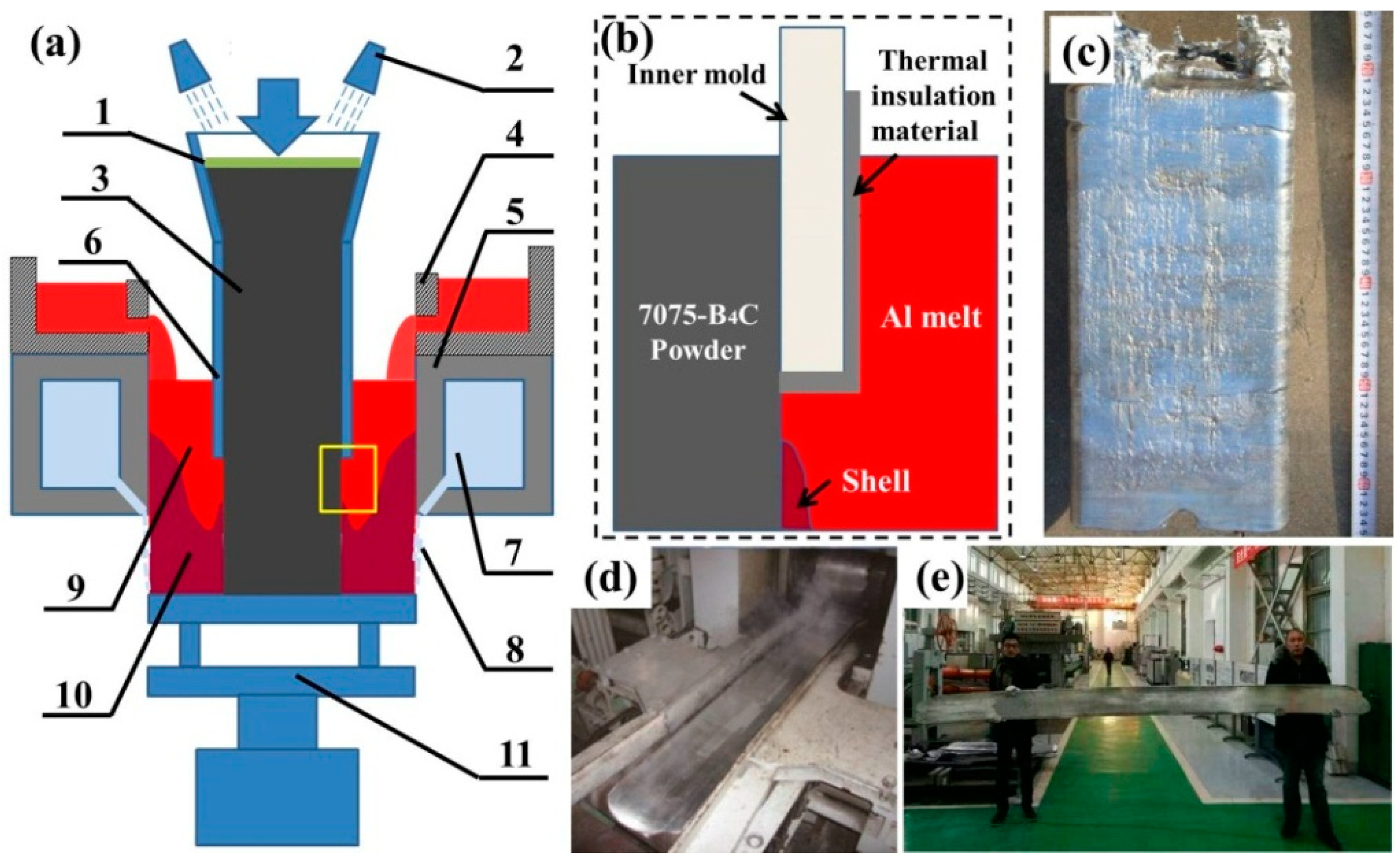
Based on the sessile drop experiment, a BRALC plate material was prepared using semi-continuous casting and hot-rolling processes. This material provided a new method to achieve both a high proportion of B4C and a large size ingot.
(3)
Uniform distribution of reinforcement B4C particles and a stable bond was achieved without defects, cavities, segregation, or excess reactions near the interface.
(4)
The BRALC exhibits evident soft–hard–soft structure, with layers of different hardness (163.4 HV of the inner layer and 32.8 HV of the outer layer) and a compression strength of 152 MPa. The material also shows a significant reduction of the bullet speed from 809.3 m/s to 327.84 m/s during the projectile impact test.

Author Contributions

Y.Z. and Y.Y. designed and performed the experiments, completed the paper; G.X. and Y.F. participated the data collection and analysis; T.L. and T.W. did experimental conception and improvement; Q.G. improved experimental equipment.

Funding

This work was financially supported by the National Natural Science Foundation of China (Nos. 51501027 and 51704029), the Open Research Fund from State Key Laboratory of Metal Material for Marine Equipment and Application (No. SKLMEA-K201701), the State Key Laboratory of Rolling and Automation, Northeastern University, and the Fundamental Research Funds for the Central Universities of China DUT17RC(4)01.

Conflicts of Interest

The authors declare no conflicts of interest.

References

  1. Wan, L.; Huang, Y. Microstructure and Mechanical Properties of Al/Steel Friction Stir Lap Weld. Metals 2017, 7, 542. [Google Scholar] [CrossRef]
  2. Cui, X.; Zhao, L.; Wang, Z.; Zhao, H.; Fang, D. A Lattice Deformation Based Model of Metallic Lattice Sandwich Plates Subjected to Impulsive Loading. Int. J. Solids Struct. 2012, 49, 2854–2862. [Google Scholar] [CrossRef]
  3. Kwon, Y.W.; Mccrillis, R.D.; Didoszak, J.M. Transient Dynamic Response and Failure of Sandwich Composite Structures under Impact Loading with Fluid Structure Interaction. Appl. Compos. Mater. 2012, 19, 921–940. [Google Scholar] [CrossRef]
  4. Ivañez, I.; Santiuste, C.; Barbero, E.; Sanchez-Saez, S. Numerical Modelling of Foam-Cored Sandwich Plates under High-Velocity Impact. Compos. Struct. 2011, 93, 2392–2399. [Google Scholar] [CrossRef] [Green Version]
  5. Erickson, M.D.; Kallmeyer, A.R.; Kellogg, K.G. Effect of Temperature on the Low-Velocity Impact Behavior of Composite Sandwich Panels. J. Sandw. Struct. Mater. 2005, 7, 245–264. [Google Scholar] [CrossRef]
  6. Wang, B.; Wu, L.Z.; Ma, L.; Feng, J.C. Low-Velocity Impact Characteristics and Residual Tensile Strength of Carbon Fiber Composite Lattice Core Sandwich Structures. Adv. Mater. Res. 2011, 42, 891–897. [Google Scholar] [CrossRef]
  7. Yazdani, A.; Salahinejad, E. Evolution of Reinforcement Distribution in Al–BC Composites during Accumulative Roll Bonding. Mater. Des. 2011, 32, 3137–3142. [Google Scholar] [CrossRef]
  8. Alizadeh, M. Comparison of Nanostructured Al/B4C Composite Produced by ARB and Al/ B4C Composite Produced by RRB Process. Mater. Sci. Eng. A 2010, 528, 578–582. [Google Scholar] [CrossRef]
  9. Lin, J.; Ran, G.; Lei, P.; Ye, C.; Huang, S.; Zhao, S.; Li, N. Microstructure Analysis of Neutron Absorber Al/ B4C Metal Matrix Composites. Metals 2017, 7, 567. [Google Scholar] [CrossRef]
  10. Zhao, Q.; Liang, Y.; Zhang, Z.; Li, X.; Ren, L. Microstructure and Dry-Sliding Wear Behavior of B4C Ceramic Particulate Reinforced Al 5083 Matrix Composite. Metals 2016, 6, 227. [Google Scholar] [CrossRef]
  11. Viala, J.C.; Bouix, J.; Gonzalez, G.; Esnouf, C. Chemical Reactivity of Aluminu with Boron Carbide. J. Mater. Sci. 1997, 32, 4559–4573. [Google Scholar] [CrossRef]
  12. Pyzik, A.J.; Beaman, D.R. ChemInform Abstract: Al-B-C Phase Development and Effects on Mechanical Properties of B4C/Al-Derived Composites. Cheminform 1996, 27, 18. [Google Scholar] [CrossRef]
  13. Kouzeli, M.; Marchi, C.S.; Mortensen, A. Effect of Reaction on the Tensile Behavior of Infiltrated Boron Carbide–Aluminum Composites. Mater. Sci. Eng. A 2002, 337, 264–273. [Google Scholar] [CrossRef]
  14. Yao, Y.T.; Chen, L.Q. B4C/Al Composites Processed by Metal-assisted Pressureless Infiltration Technique and Its Characterization. Adv. Manuf. Process. 2016, 31, 1286–1291. [Google Scholar] [CrossRef]
  15. Lai, J.; Zhang, Z.; Chen, X.G. Effect of Sc and Zr alloying on Microstructure and Precipitation Evolution of as Cast Al–BC Metal Matrix Composites. Met. Sci. J. 2014, 28, 1276–1286. [Google Scholar] [CrossRef]
  16. Alizadeh, A.; Taheri Nassaj, E.; Hajizamani, M. Investigation of Mechanical Behavior of Stir Casted Al Based Composites Reinforced with B4C Nanoparticles. Adv. Mater. Res. 2011, 383–390, 2728–2732. [Google Scholar] [CrossRef]
  17. Zhang, L.; Shi, J.; Shen, C.; Zhou, X.; Peng, S.; Long, X. B4C-Al Composites Fabricated by the Powder Metallurgy Process. Appl. Sci. 2017, 7, 1009. [Google Scholar] [CrossRef]
  18. Varol, T.; Canakci, A. Effect of Weight Percentage and Particle Size of B4C Reinforcement on Physical and Mechanical Properties of Powder Metallurgy Al2024-B4C Composites. Met. Mater. Int. 2013, 19, 1227–1234. [Google Scholar] [CrossRef]
  19. Seetharam, R.; Subbu, S.K.; Davidson, M.J. Hot Workability and Densification Behavior of Sintered Powder Metallurgy Al-B4C Preforms during Upsetting. J. Manuf. Process. 2017, 28, 309–318. [Google Scholar] [CrossRef]
  20. Zhang, Z.; Topping, T.; Li, Y.; Vogt, R.; Zhou, Y.; Haines, C.; Paras, J.; Kapoor, D.; Schoenung, J.M.; Lavernia, E.J. Mechanical Behavior of Ultrafine-Grained Al Composites Reinforced with BC Nanoparticles. Scr. Mater. 2011, 65, 652–655. [Google Scholar] [CrossRef]
  21. Wu, C.; Ma, K.; Wu, J.; Fang, P.; Luo, G.; Chen, F.; Shen, Q.; Zhang, L.; Schoenung, J.M.; Lavernia, E.J. Influence of Particle Size and Spatial Distribution of B4C Reinforcement on the Microstructure and Mechanical Behavior of Precipitation Strengthened Al Alloy Matrix Composites. J. Mater. Sci. Eng. A 2016, 675, 421–430. [Google Scholar] [CrossRef]
  22. Hofmeister, C.; Giri, A.; Brennan, S.; Brennan, S.; Sohn, Y.H.; Delahanty, T.; Cho, K. Effect of Process Control Agent on the Microstructure and Mechanical Behavior of an Aluminum and B4C Metal Matrix Composite. In Light Metals; Springer: Cham, Switzerland, 2014; pp. 1343–1346. [Google Scholar] [CrossRef]
  23. Bao, S.; Tang, K.; Kvithyld, A.; Engh, T.; Tangstad, M. Wetting of Pure Aluminium on Graphite, SiC and Al2O3 in Aluminium Filtration. Trans. Nonferrous Met. Soc. China 2012, 22, 1930–1938. [Google Scholar] [CrossRef]
  24. Hashim, J.; Looney, L.; Hashmi, M.S.J. The Wettability of SiC Particles by Molten Aluminium Alloy. J. Mater. Process. Technol. 2001, 119, 324–328. [Google Scholar] [CrossRef]
  25. Ksiazek, M.; Sobczak, N.; Mikulowski, B.; Radziwill, W.; Surowiak, I. Wetting and Bonding Strength in Al/Al2O3 System. Mater. Sci. Eng. A 2002, 324, 162–167. [Google Scholar] [CrossRef]
Figure 1. Schematic diagram of (a) the sessile drop experiment equipment and (b) the droplet–substrate contacting condition.
Metals 08 00600 g001
Figure 2. The schematic diagram of (a) the semi-continuous casting equipment, with (1) pressing plate, (2) Ar gas shield, (3) powder mixture, (4) runners, (5) outer mold (crystallizer), (6) inner mold, (7) circulating cooling water, (8) second cooling water, (9) Al melt, (10) Al shell, and (11) drawing drive; (b) a detail of interfacial combination between layers near the inner mold; (c) ingot obtained by continuous casting; (d) the boron carbide-reinforced aluminum layered composite (BRALC) plate with a thickness of 20 mm at the final step during hot rolling; and (e) the thinnest BRALC plate (3 mm) after further rolling.
Metals 08 00600 g002
Figure 3. The schematic diagram of the bullet impact test.
Metals 08 00600 g003
Figure 4. (a) Photographs of the infiltration and spreading process of the Al-Si melt onto the 7075-B4C substrate; and (b) the time-dependent variation of the contacting angle and size of the droplet.
Metals 08 00600 g004
Figure 5. (a) The macrostructure of three-layered composite cross-section, and the microstructures of (b) the inner 7075-B4C layer and (c) interface between layers, as well as (d) a magnified morphology of the optional B4C particle from the inner layer; (e) a magnified interfacial morphology between B4C, the 7075 matrix, and the marked line scanning position; and (f) the line-scanning analysis results for the Al, B, Cu, Zn, and Mg elements.
Metals 08 00600 g005
Figure 6. (a) Hardness test and (b) compression results of the BRALC.
Metals 08 00600 g006
Figure 7. (a) Macrostructure of the BRALC ballistic trajectory and (b) the microstructure of the interface on the bullet crater.
Metals 08 00600 g007
Figure 8. (a) Schematic of the possible positions of B4C particles on the bullet penetrating direction, (b) protrusions of B4C particles, (c) fragment of B4C particles, and (d) pits induced by the B4C particles falling off the surface of the ballistic trajectory.
Metals 08 00600 g008
Table 1. Chemical composition of commercially pure aluminium (CPAl) and 7075 alloy powder (wt %).
ElementAlFeSiZnMgMnCuCrBTiNiCa
CPAlBal.0.130.040.0140.0010.0010.001-----
7075900.40.55.62.60.181.60.20.0050.20.030.02

