Abstract
The machinability of graphene-reinforced magnesium-based hybrid nanocomposites produced through the application of powder metallurgy method has not been completely reported. This article presents an experimental investigation on the thrust force, the surface roughness (Ra), and drilled surfaces characteristics in the drilling process of a Mg/SiC/GNPs (magnesium matrix based silicon carbide and graphene nanoplatelets) hybrid magnesium matrix composite. The hybrid composite material was produced through the application of a powder metallurgy method. The experiments were carried out with uncoated, PVD (Physical Vapor Deposition), and CVD (Chemical Vapor Deposition) coated tungsten carbide drill bits at three levels of cutting speeds (30, 40, and 50 m/min), and three different levels of feed rate (0.10, 0.15, and 0.20 mm/rev) under dry machining conditions. Taguchi’s L27 (33) orthogonal array and S/N ratio were used to optimize the optimal parameters for thrust force and surface roughness. The experimental results indicated that the thrust force and the surface roughness were extremely dependent on a particular type of drill bits, feed rate, and cutting speed. The feed rate parameter is known to have a significant influence on the surface finish.
1. Introduction
Metal matrix composites (MMCs) are mainly used in a large domain due to their excellent properties (properties-to-weight) of strength and stiffness compared to monolithic metals, and they show some capable degree of latency for novel products proposed and produced [1,2,3,4,5]. MMCs are anisotropic, non-homogeneous materials and reinforced with abrasive reinforcements. This formulates hard materials to cut/machine [6,7]. Magnesium is preferred as the lightweight structural metal. Magnesium is lighter than aluminum, titanium, and stainless steels by 33%, 61%, and 77%, respectively [4,8]. Mg MMC presents several advantages compared to Mg metal or its alloys, such as a high modulus of elasticity, high strength, and excellent creep properties [6,8,9]. The desired properties are achieved by a careful selection of the size and the kind of the reinforcement particles. The reinforced materials mainly used are SiC (silicon carbide), TiC (titanium carbide), Al2O3 (aluminum oxide), B4C (boron carbide), CNTs (carbon nano-tubes), and the new graphene nano-platelets (GNPs) [9,10,11]. Rashad et al. [9] succeeded in producing magnesium GNPs composites (Mg/0.3wt%GNPs) through a semi-powder metallurgy process. Through the addition of 0.3wt%GNPs to the Mg matrix, it generated an improvement up to 10.0%, 5%, 8%, and 19.3% for the modulus of elasticity, tensile strength, ultimate tensile strength, and Vickers hardness, respectively. An experimental investigation, was done by Li and Lu [1] on the machinability of Mg-Al-SiC MMC, in terms of tool flank wear, has shown that flank wears increased gradually with the increase of the SiC particle fraction volume, due to the abrasive character of the SiC particles. Rajmohanet et al. [2] performed a drilling process on hybrid Al356/SiC-mica MMC. Their results indicated that a low feed rate is preferred in the drilling of this MMC, and that the increase in the feed rate increases the thrust force and leads to a poor surface finish, and the increase in the cutting speed reduces the surface roughness. Sahin and Sur [3] suggested a lower cutting speed while machining coarse particle-reinforced MMCs and a higher cutting speed for machining fine particle-reinforced MMC. Saravanakumar et al. [12], reported that the cutting speed and the feed rate have a major influence on the surface quality of the machined surfaces during machining of a magnesium composite (AZ91D/5%Gr), and the presence of graphite reinforcement acts as a solid lubricant that improves the surface finish. A study carried out by Muniaraj et al. [13] experimentally investigated the influence of the drill geometry on the surface finish in the drilling process of hybrid Al/SiC/Gr MMC. The results indicated that the increase of the cutting speed reduce the surface roughness, whereas the increase of the feed rate increases the surface roughness, and they reported that the feed rate is the factor which extremely influences the surface finish in the drilling of hybrid MMCs. For metal matrix composites (MMCs), though challenging to manufacturing engineers and researchers at the beginning, MMCs can be machined using conventional cutting processes, such as turning, drilling, milling, etc. Drilling operations remain the most essential machining process in various applications, such as automotive, aircraft, and aerospace fields, dies and molds, medical and electronic equipment industries, and by operations involving the creation of holes for different kinds of materials. For fastening and tie purposes, drilling is most commonly used for MMCs. Drilling of MMCs poses many problems to manufacturing engineers, such as high drilling forces, tool wear, delamination, and poor surface finish.
In the literature, there are limited studies about graphene-reinforced magnesium matrix hybrid composites that are produced through the application of the powder metallurgy method. Researchers have generally attempted to evaluate the mechanical properties of these innovative materials, but there is no research study about the machinability of graphene-reinforced magnesium-based hybrid nanocomposites. The purpose of this study is to investigate the influence of drilling parameters on the thrust force and the surface roughness (Ra) during the drilling process of Mg/SiC/GNPs hybrid MMC while using the uncoated, PVD (Physical Vapor Deposition), and CVD (Chemical Vapor Deposition) coated tungsten carbide drill bits at different levels of cutting speeds and feed rates, in order to improve the level of understanding in the processing of the Mg-based MMCs.
2. Experimental Procedure
2.1. Composite MaterialSynthesis
The matrix material was used for the production of the hybrid composite is magnesium powder of 99.7% purity with an average particles size of 100 µm. The reinforcements were GNPs and silicon carbide SiC. The GNPs had an average thickness of 5–8 nm and the surface area was about 750 m2/g. The silicon carbide particles were of 99.7% purity, with an average particles size of 40 µm. The Mg/10 wt %SiC/0.25 wt %GNPs hybrid MMC was produced by the powder metallurgy method. The matrix and reinforcements were mixed using the mechanical alloying device for two hours with a speed of 250 rpm. A stainless steel mold 25 mm in internal diameter was used for the cold pressing process. The powders were pressed by applying a pressure of 500 MPa at room temperature. This process produced the green samples with a diameter of 25 mm and a thickness of 10 mm. The samples were sintered for 1.5 h at a temperature of 550 °C under the controlled atmosphere of high-purity argon gas to prevent oxidation due to the low oxidation resistance of magnesium.
2.2. Experimental Design
The Taguchi method was used for designing of the experiments. The L27 (33) orthogonal array with 27 rows was used for the experiments. The experiments were performed under a dry machining condition at different cutting speeds of 30, 40, and 50 m/min, with feed rates of 0.10, 0.15, and 0.20 mm/rev. The drilling tests were carried out using the uncoated, PVD, and CVD coated tungsten carbide drill bits 5 mm in diameter. Table 1 and Table 2 show the drill bit specifications and the cutting parameter levels, respectively. Table 3 presents the L27 Taguchi’s orthogonal array design for the tests.

Table 1.
Drill bits specifications.
Table 2.
Cutting parameters and levels.
Table 3.
L27 (33) Taguchi’s orthogonal array design for tests.
2.3. Measurement of Cutting Thrust Force
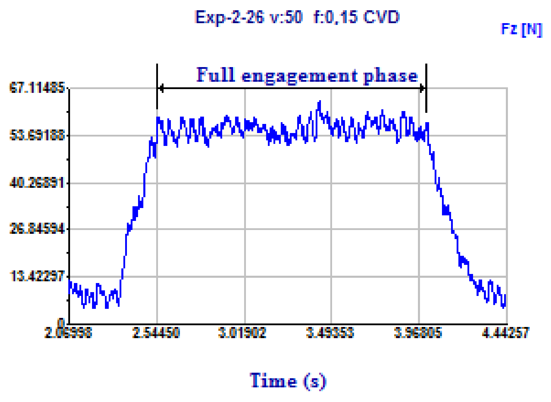
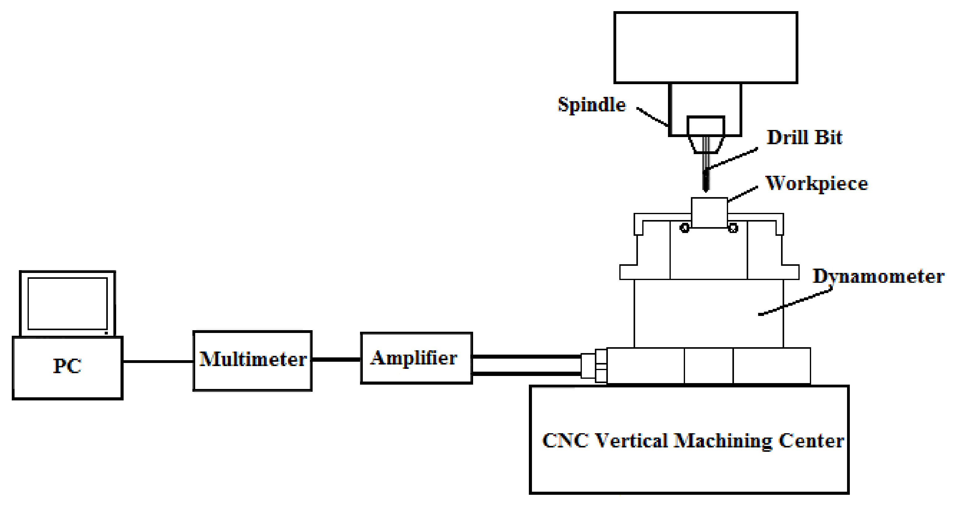
The drilling experiments were performed on a Johnford VMC-550 (Johnford machinery industries CO., LTD, Taiwan) vertical machining center (maximum rotation speed of 6000 rev/min and 7.5 kW power). The developed thrust force was recorded by using the data acquisition system. A piezo-electric dynamometer (Kistler model 9272-A; Kistler Instrument AG, Winterthur, Switzerland) was used to measure the thrust forces. The dynamometer was connected to the Kistler 5070-Amulti-channel charge amplifier (Kistler Instrument AG, Winterthur, Switzerland). First, the signals were recorded and sent from the dynamometer to the data reading card (Kistler PCIM DAS 1602/16) then to the Kistler 5070-A multi-channel amplifier and, finally, the recorded signals were stored and processed with Kistler Dynoware 2825D-02 software (version 2.6.5.16, Kistler Instrument AG, Winterthur, Switzerland). The mean thrust force values were measured at the full engagement phase of the drill bit and the MMC material interface, as presented in Figure 1. The schematic of the experiment setup for the measuring of the thrust force is shown in Figure 2.

Figure 1.
Thrust force profile vs. machining time for the experimental run at Vc = 50 m/min and f = 0.15 mm/rev when using the CVD-coated drill bit.
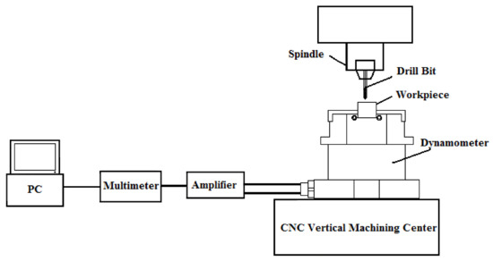
Figure 2.
Schematic of the experiment setup for measuring the thrust force.
2.4. Surface Roughness (Ra) Measurement
Surface roughness can be defined as the average of the vertical divergences from the nominal surface over a specific surface interval. An arithmetic mean (Ra) of roughness is generally used. The surface roughness (Ra) was measured with a Mitutoyo SJ-410 surface device (Mitutoyo GmbH, Neuss, Germany) with a cut-off interval of 4.8 mm and speed of 0.5 mm/s. The surface roughness value was used to exemplify the drilled surface quality. The measurement of the surface roughness was performed parallel to the axis of the drilled hole in three different positions, and the average values of (Ra) were adopted and scrutinized in the analysis.
3. Experimental Results and Discussion
3.1. Microstructural Characterization
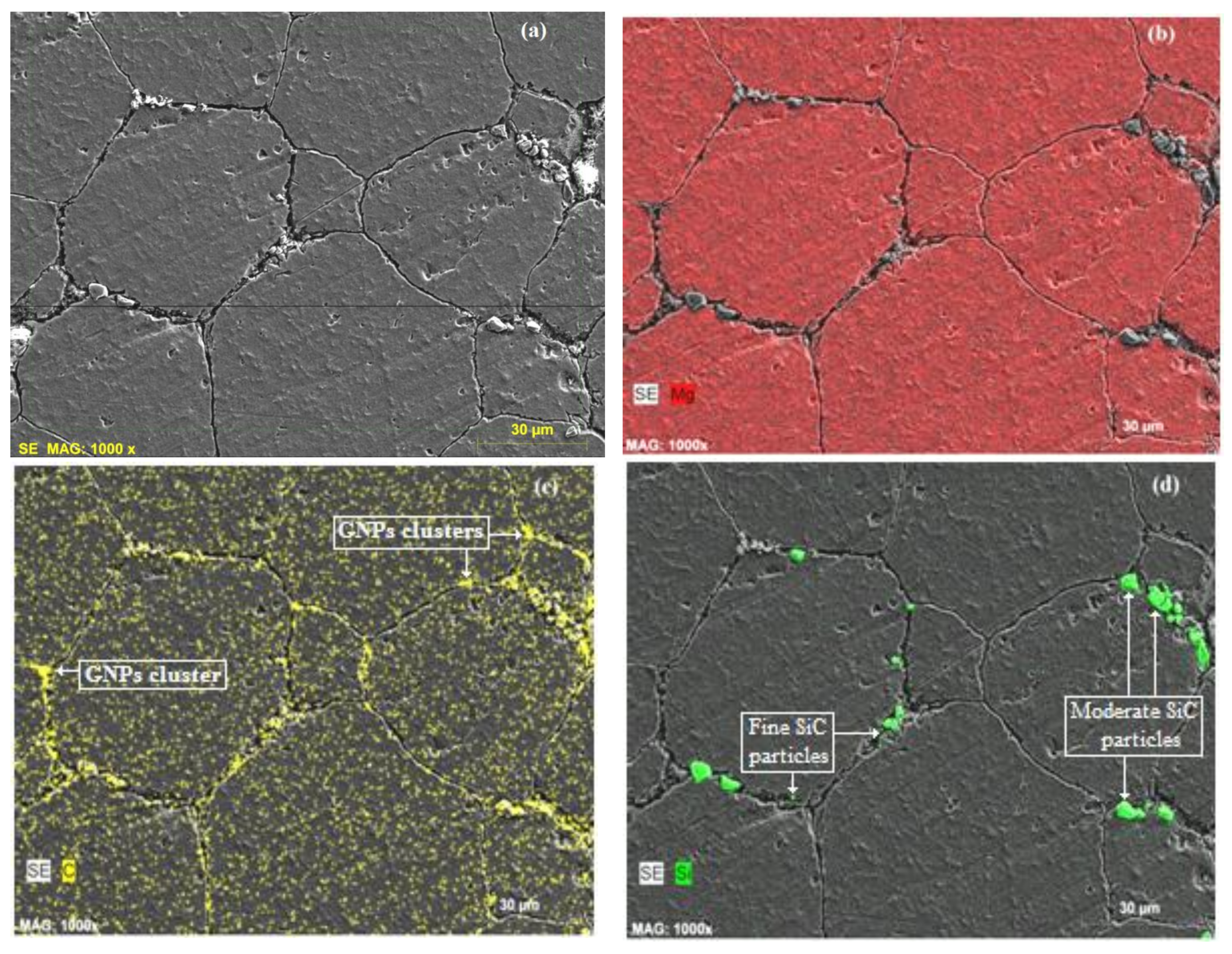
Scanning electron microscopy (SEM) (1000× magnification) was used to study the surface morphology of the Mg/10 wt %SiC/0.25 wt %GNPs hybrid MMC. Figure 3 shows the SEM images of the hybrid MMC. The distribution of the reinforcement (GNPs and SiC) into the Mg matrix is also given in the figure. It can be seen that the microstructure consists of the matrix (Mg) phase grains encompassed by the reinforcement particles phase, the reinforcement particles are situated principally along the matrix grain boundaries. The microstructure is free of macrostructural defects, such as macro-porosities and cracks. However, there were limited oxidations in the matrix material as a result of the low corrosion resistance of the magnesium based composite. The images show that there exists significant bonding between (GNPs, SiC) and Mg matrix particles. A careful inspection of the SEM image is shown in Figure 3d; it shows that moderate and fine SiC particles exist. The SEM image in Figure 3c shows the uniform distribution of carbon (GNPs) in the matrix materials with a few clusters. Additionally, from Figure 4d, it can be seen that the SiC particles tend to locate around the GNPs clusters.

Figure 3.
(a) SEM surface image of Mg/10wt%SiC/0.25wt%GNPs hybrid MMC; (b) X-ray mapping of Mg matrix; (c) distribution of carbon (GNPs); and (d) distribution of SiC particles.
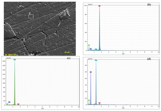
Figure 4.
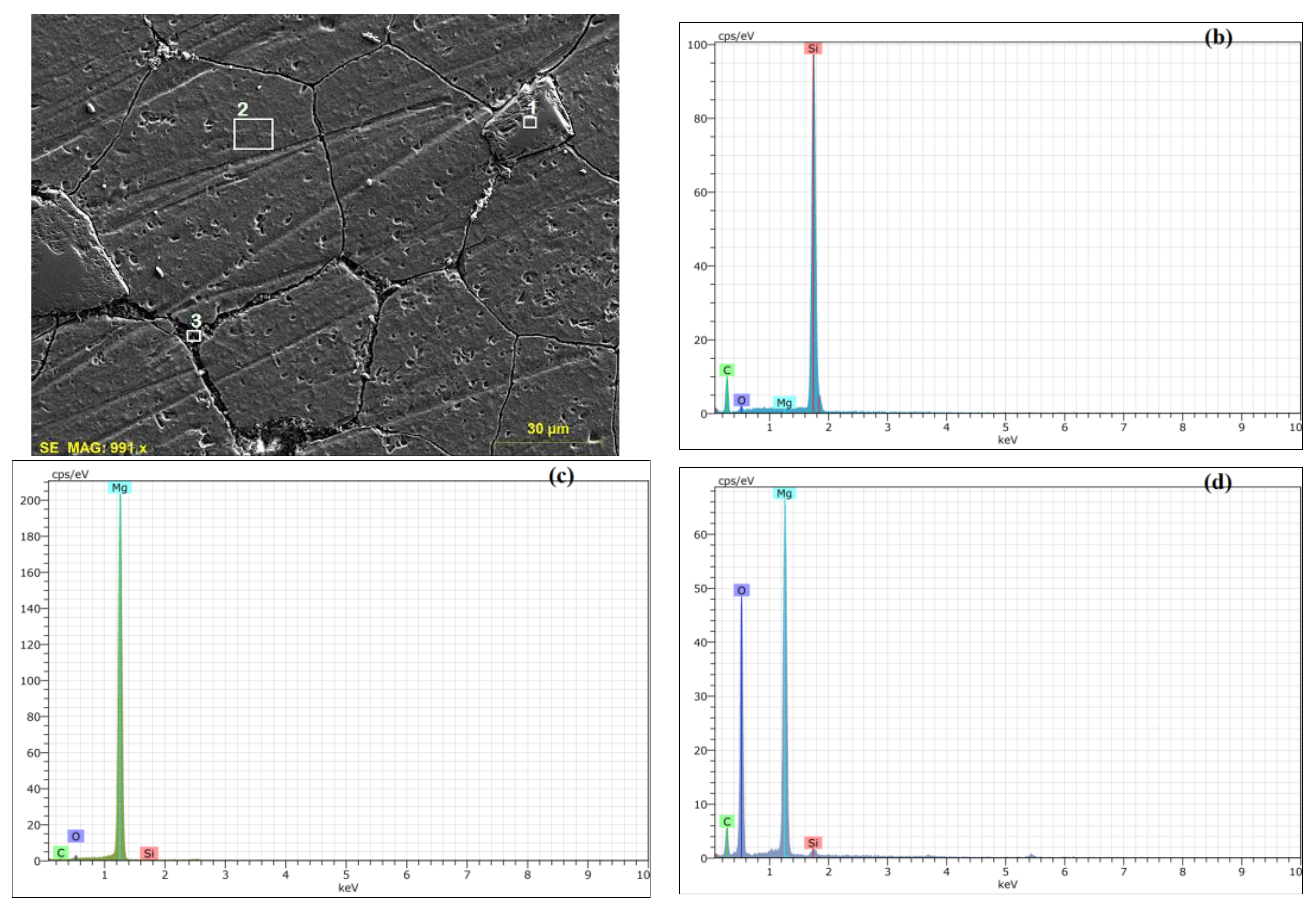
(a) SEM image of Mg/10 wt %SiC/0.25 wt %GNPs hybrid MMC; (b) EDS peaks for area No. 1; (c) EDS peaks for area No. 2; and (d) EDS peaks for area No. 3.
Figure 4a shows the SEM surface image of Mg/10 wt %SiC/0.25 wt %GNPs hybrid MMC with selected areas for EDS (Energy Dispersive Spectroscopy) peaks as shown in Figure 4b–d. Carbon peak in the EDS assured the existence of a carbonaceous composition in the Mg/10wt%SiC/0.25wt%GNPs hybrid MMC, while the small peak of oxygen reflected the small level of oxidation through a sintering process. Area 1 has more carbon content than other areas due to the existence both of SiC and GNPs. It can be also attributed that there are Van der Waals bonding between carbon atoms in GNPs. This bonding might lead to agglomerations of GNPs in the magnesium matrix [10].
3.2. Thrust Force
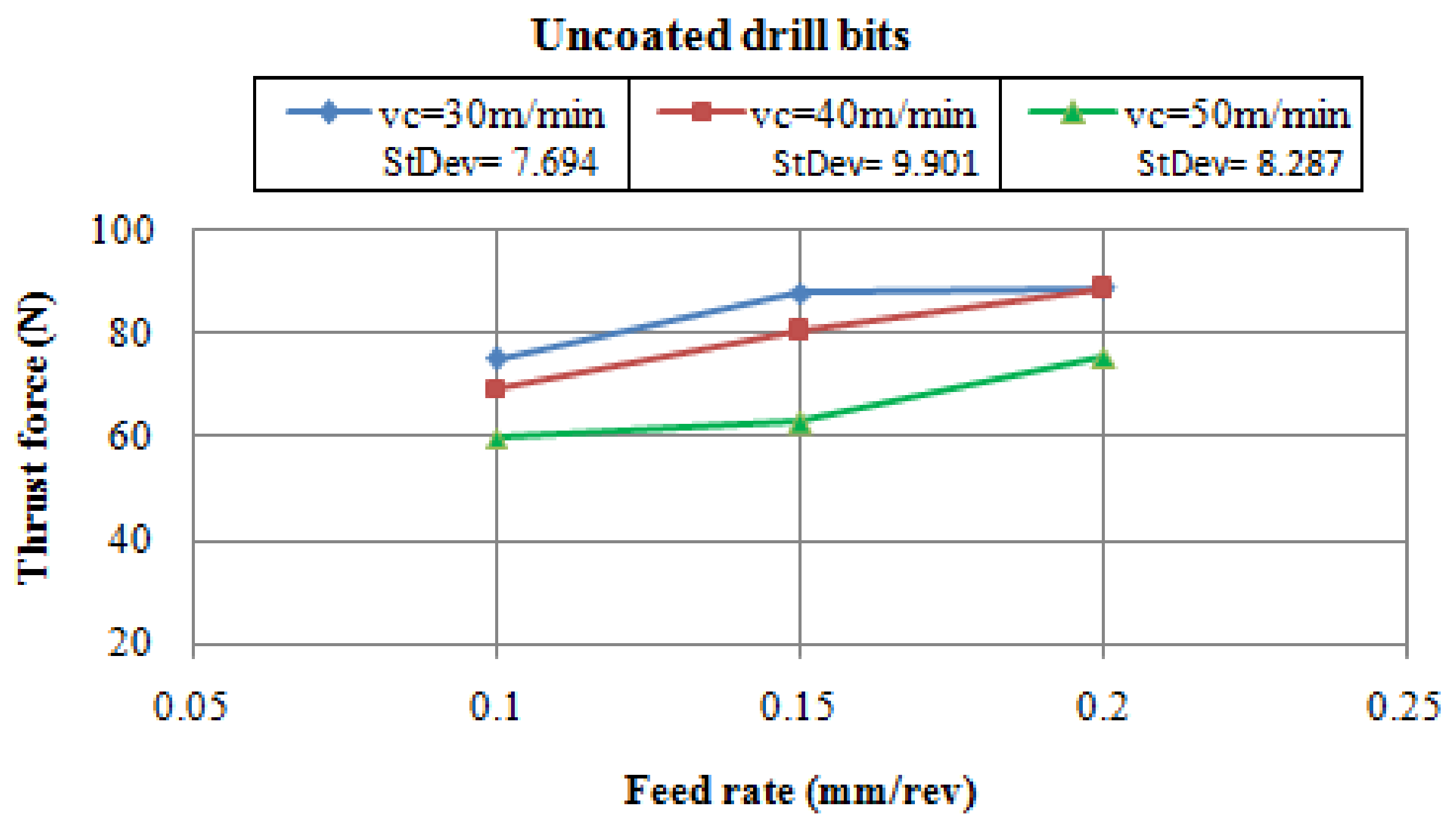
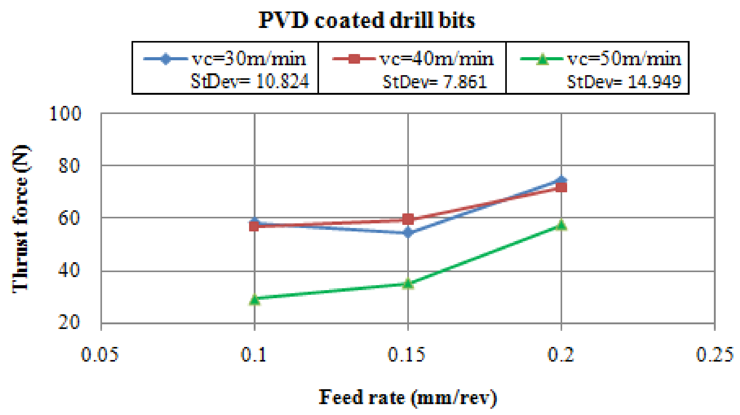
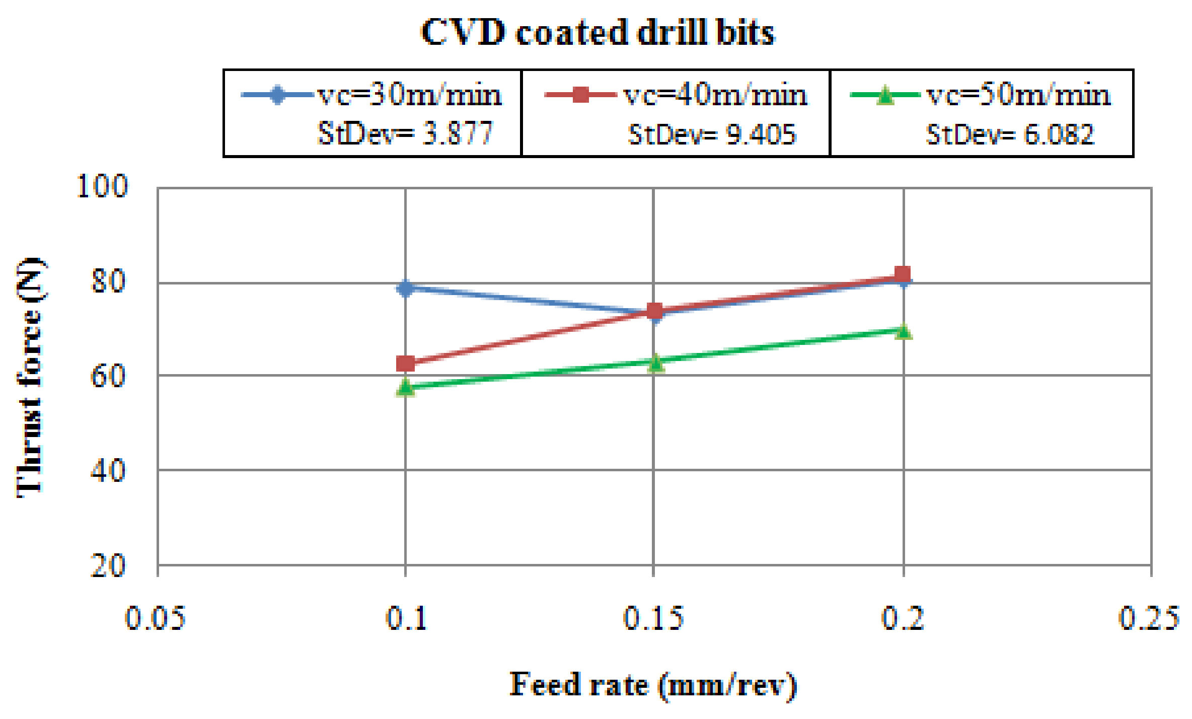
Figure 5, Figure 6 and Figure 7 show the variation of the thrust force with feed rates at different cutting speeds for Mg/10 wt %SiC/0.25 wt %GNPs hybrid MMC when using uncoated, PVD and CVD coated drill bits respectively. The thrust force in the drilling process of MMCs mostly depends on the matrix material and reinforced elements composition, interface, and properties [2].
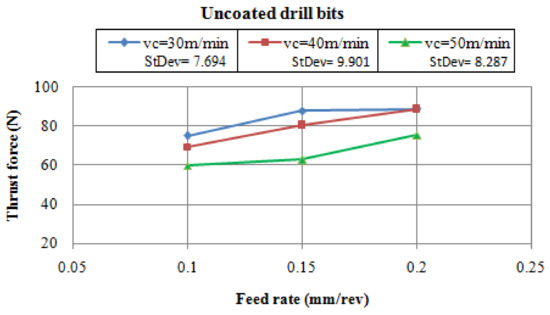
Figure 5.
Thrust force variation with feed rates at different cutting speeds when using uncoated drill bits.
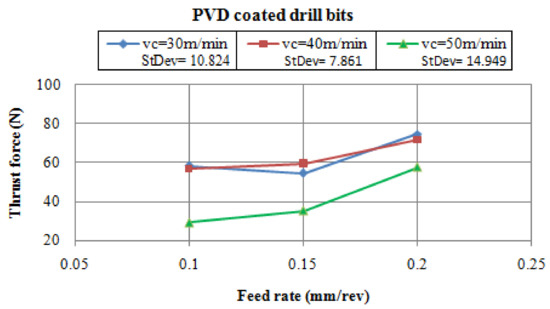
Figure 6.
Thrust force variation with feed rates at different cutting speeds when using PVD-coated drill bits.
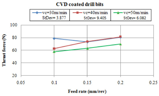
Figure 7.
Thrust force variation with feed rates at different cutting speeds when using CVD-coated drill bits.
The figures showed that the thrust force was extremely dependent on the feed rate, cutting speed, and the type of drill bits [12,13,14,15]. The differences between the thrust force values become lower at 30 and 40 m/min cutting speeds while using the PVD-coated drill bits when compared to the higher cutting speed (50 m/min). In most tests, the experimental results indicated that the thrust force increased by increasing the feed rate, while the thrust force decreased with the increasing of the cutting speed. This was related to the fact that the increase in heat generation on the cutting area softens the Mg matrix and leads to the easy plastic deformation. This worked to weaken the bonds between the (GNPs, SiC) reinforcements and the Mg matrix [2]. Additionally, in most of the experiments, the thrust forces were lower when using the coated drill bits as compared to the uncoated drill bits at the three levels of feed rate. This result was linked to the nature of the GNPs, that GNP particles reduce the friction on the cutting edge-material interface and between the cutting edge and chips shaped due to their naturalistic solid lubricant characteristic, and with a hard coating layer which reduced the built-up-edge (BUE) formation leading to efficient lubrication [12,14].
Generally, for all the results obtained, the thrust force values were close to each other while using cutting speeds of 30 and 40 m/min at a feed rate of 0.20 mm/rev, and the thrust force increases with the increasing feed rate, which this varies with the three levels of cutting speeds. The lesser thrust force value was obtained at a cutting speed of 50 m/min in all the experimental tests at each level of feed rate. Further, the lowest thrust force value was during the use of PVD-coated drill bits for each level of feed rate, as shown in Figure 6. The figure also shows that with the increased feed rate, the thrust force increases as well. The standard deviation of the thrust force values at a cutting speed of 50 m/min while using PVD-coated drill bits is 14.949, this shows the gradient increase in the thrust force with the increase of the feed rate. Figure 7 shows that the thrust forces are almost equal at cutting speeds of 30 and 40 m/min, and feed rates of 0.15 and 0.20 mm/rev, but there is a significant difference between them at a feed rate of 0.10 mm/rev.
The Taguchi’s technique applies the signal-to-noise ratio (S/N ratio) to calculate the characteristic value deviate from the desired value [2]. A signal to noise (S/N) ratio is used to characterize the control parameter that minimizes the effect of noise on the response. Minitab18 software (version 18.1, Installation ID: 49297311911403558556 trial, Minitab Inc, State College, PA, USA) calculates an individual (S/N) ratio for each parameter combination. A smaller value reflects a better property type of the S/N ratio, which was used in this analysis. The formula for the smaller is the better S/N ratio is:
where X is the given responses for parameter level combination and n is the response number in the parameter level combination.
S/N = −10·log (Σ (X2)/n)
The experimental results were transformed to the S/N ratios, the parameter with the higher differentiation between the mean of S/N ratios was the most significant control parameter. The response table can specify which parameter has the major influence on the response (thrust force) and which parameter level is linked to the upper or lower response characteristic values. Minitab employs the following procedure to form the response table: (1) compute the chosen response characteristic for each parameter level combination; (2) for each parameter, Minitab computes the average of the response characteristic at each parameter level; (3) for each parameter, Minitab computes the delta value that is the highest average response characteristic value minus the lowest average response characteristic value for the parameters levels; and (4) calculate the order (rank) of the parameters, which is the order of the delta values from high to low. Table 4 shows the ranks of the parameters resulted by S/N ratio analysis via Minitab 18 software for the different parameter levels for the thrust force. Table 4 also shows that the most significant parameter affecting the thrust force was the type of drill, followed by the cutting speed and then feed rate.
Table 4.
S/N ratio response table (smaller is better) of thrust force for (Mg/SiC/GNPs) hybrid MMC.
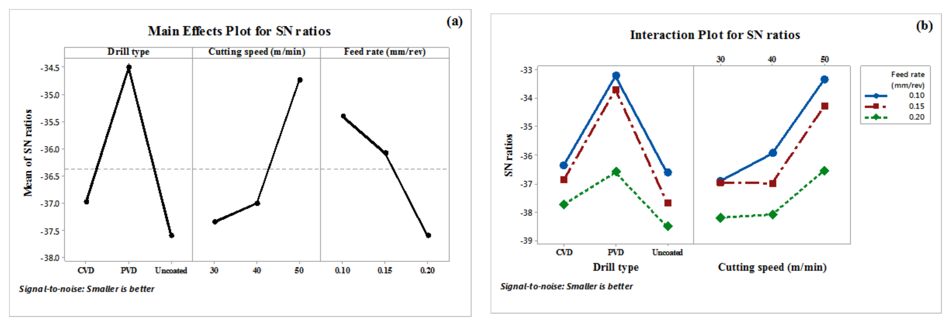
Figure 8a shows the plot of S/N ratio of the thrust force for Mg/10 wt %SiC/0.25 wt %GNPs hybrid MMC. The figure shows that the optimal parameter combination to reach the minimum value of the thrust force were the PVD-coated drill bit, a cutting speed of 50 m/min, and a feed rate of 0.10 mm/rev. Figure 8b presents the interaction plot generated by Minitab software showing the interactions between the parameters (cutting speed, feed rate, and type of drill bit). Minitab software forms the interaction plot through plotting the characteristic average of two parameters for each combination of parameter levels.
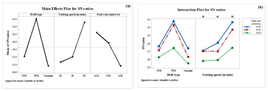
Figure 8.
(a) Plot of main effects for S/N ratio; and (b) interaction plot for S/N ratios; of thrust force for (Mg/SiC/GNPs) hybrid MMC.
3.3. Surface Roughness (Ra)
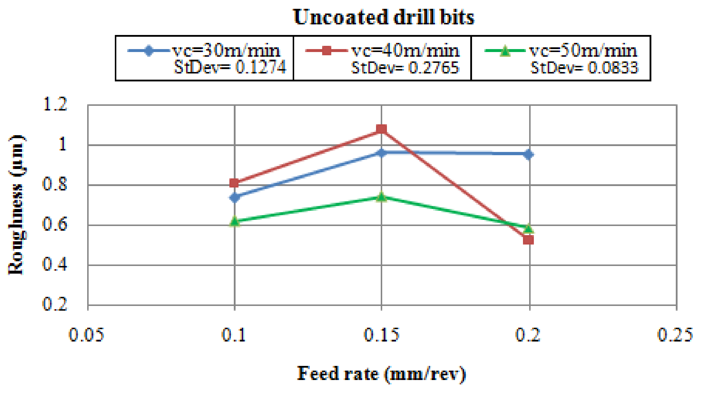
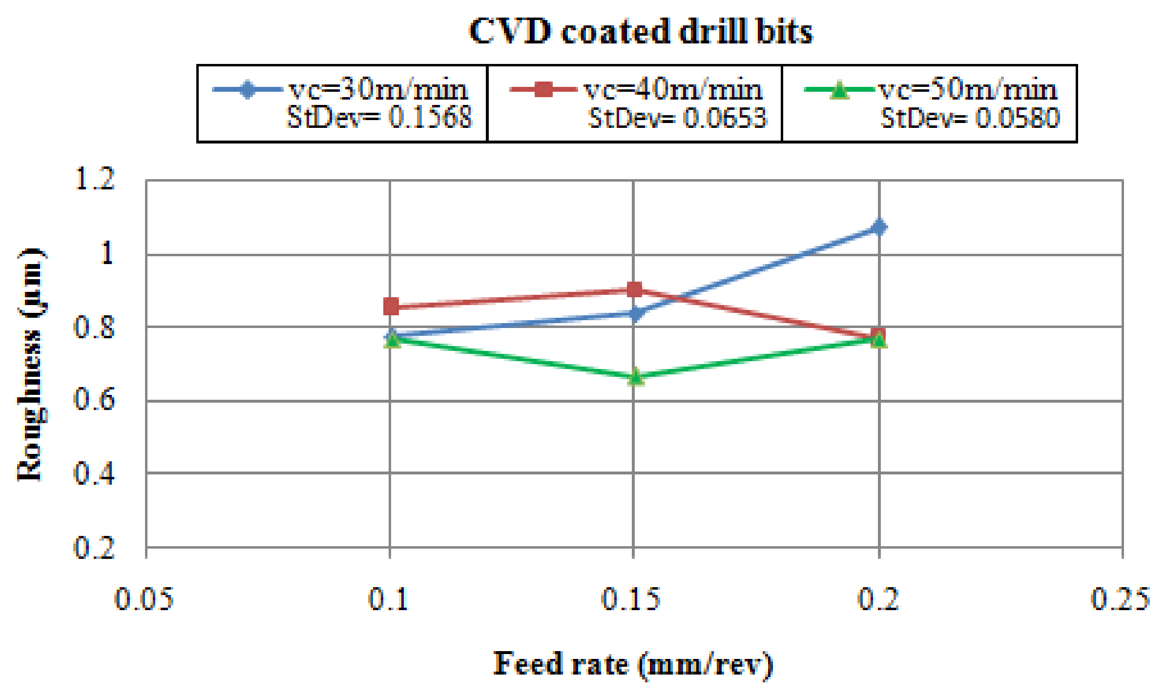
The variant in the surface roughness (Ra) values for drilled surfaces of the Mg/SiC/GNPs hybrid MMC under the cutting parameters for uncoated, PVC and CVD-coated drill bits were presented in Figure 9, Figure 10 and Figure 11, respectively. The increases in the cutting speed decreased the surface roughness in the drilling of the Mg/SiC/GNPs hybrid MMC while using the CVD-coated drill bits. At the high cutting speeds, the cutting edge pressure increased and cuts the hybrid MMC smoothly and generated less surface roughness, and vice versa, at the lower cutting speeds [14].
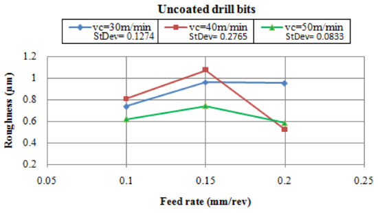
Figure 9.
Surface roughness with feed rates at different cutting speeds when using uncoated drill bits.
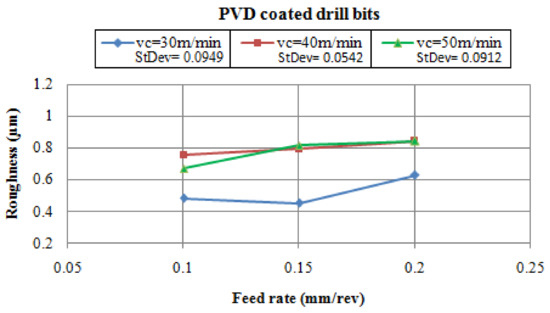
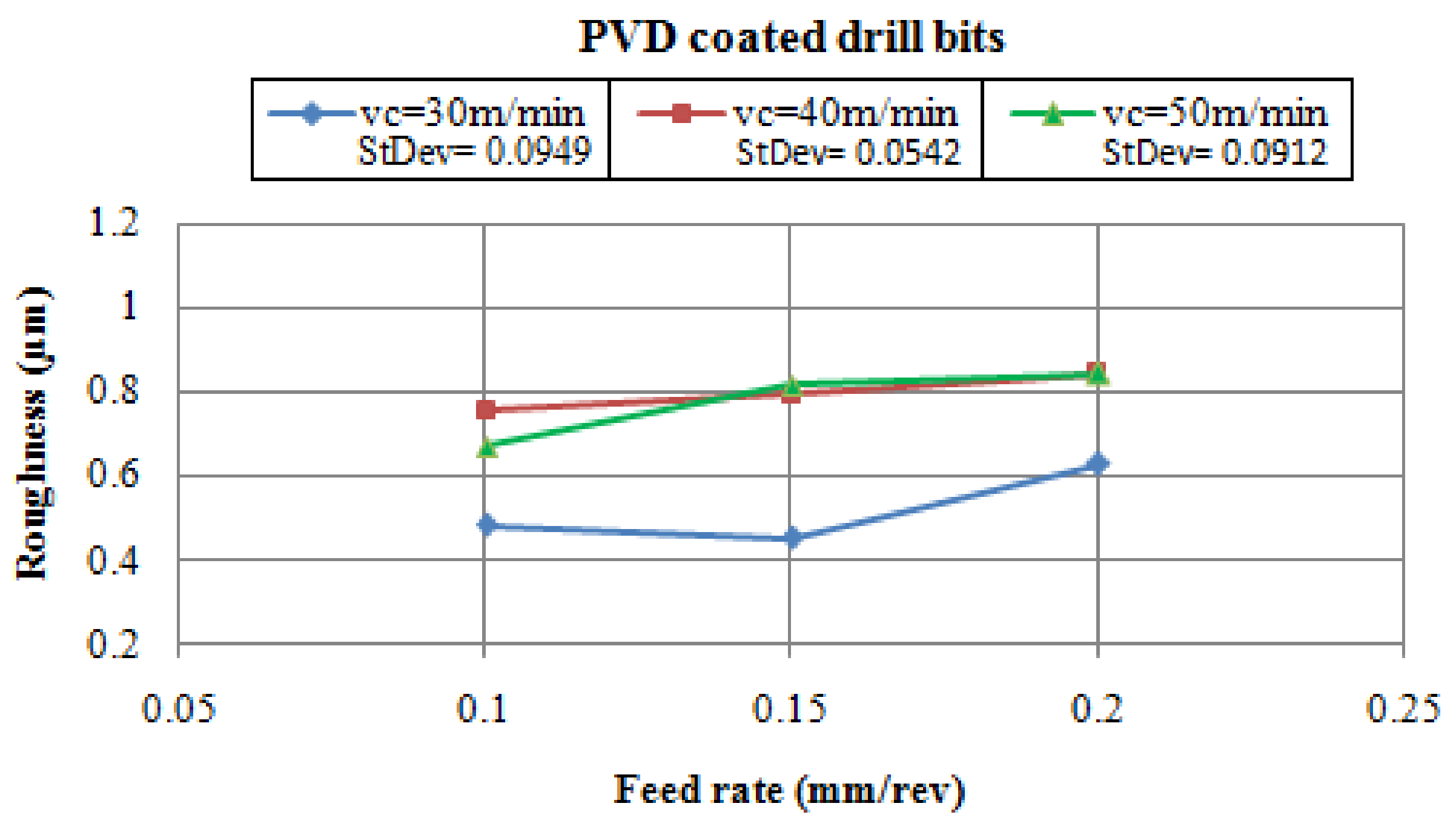
Figure 10.
Surface roughness with feed rates at different cutting speeds when using PVD-coated drill bits.
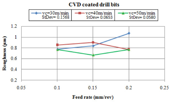
Figure 11.
Surface roughness with feed rates at different cutting speeds when using CVD-coated drill bits.
The surface roughness (Ra) values of drilled surfaces are lower when using PVD-coated drill bits with a cutting speed of 30 m/min at a 0.15 mm/rev level of feed rate, and with the usage of CVD-coated drills at Vc = 50 m/min and f = 0.15 mm/rev. This is due to the tough coating layers over the drill bit surface, which reduced the BUE formation during the drilling process [6,12,16]. Figure 10 shows that the lowest values of surface roughness were obtained while using PVD-coated drill bits with a cutting speed of 30 m/min and feed rates of 0.10 and 0.15 mm/rev. The figure also shows that the surface roughness values are roughly equal at cutting speeds of 40 and 50 m/min with feed rates of 0.15 and 0.20 mm/rev. For most tests, the results specify that lower feed rate (0.10 mm/min) and lower cutting speed (30 m/min) is preferred in the drilling of hybrid Mg/SiC/GNPs MMC, the increase in the feed rate value increases the thrust force and this affects the surface finish [12,14]. The surface roughness increases when using the higher feed rates (0.20 mm/rev) while using the coated drill bits at lower (30 m/min) and higher (50 m/min) cutting speeds. This is because of the increase in the friction between the cutting edge and the surfaces, which increases the temperature in the cutting region. At a high temperature, the Mg matrix behaves in a ductile mode due to the reduction in the shear strength. This increases the BUE formation, which increases the surface roughness [16,17]. When uncoated drill bits are used, the highest value of surface roughness is obtained when using the cutting speed of 40 m/min at a feed rate of 0.15 mm/rev, then a significant decrease in the value of surface roughness occurs at a feed rate of 0.20 mm/rev.
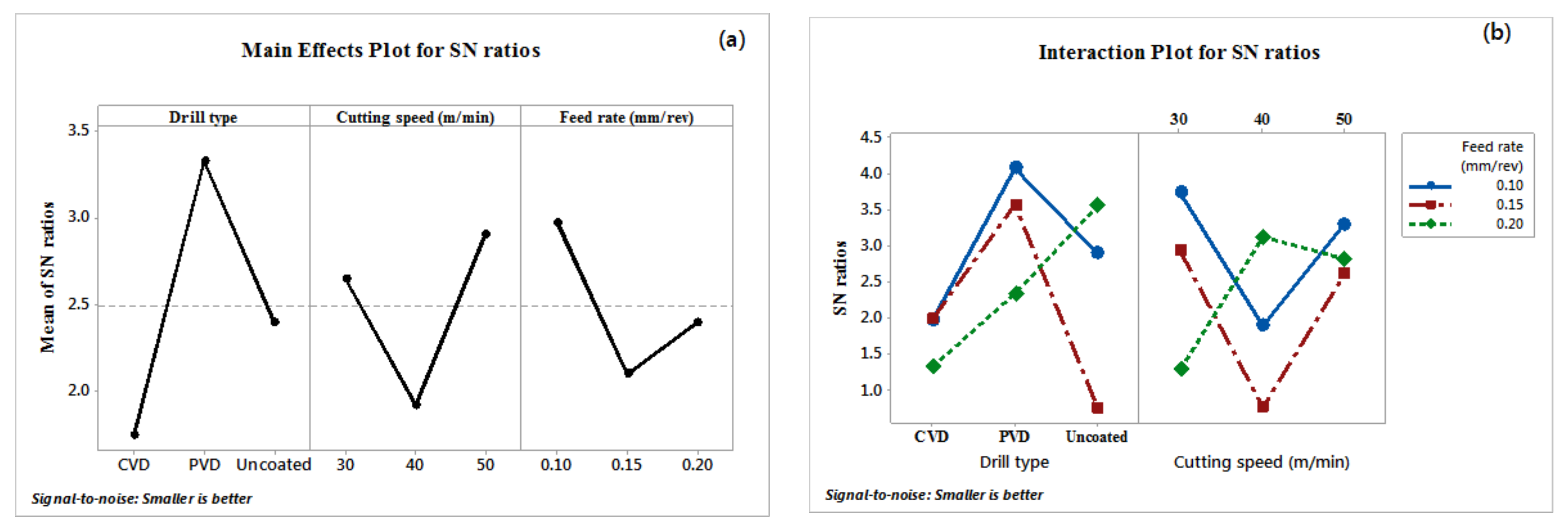
The ranks of the parameters result recoded through the S/N ratio analysis via the Minitab 18 software for the different parameters levels of the surface roughness (Ra) for Mg/SiC/GNPs hybrid MMC were shown in Table 5. The table shows that the significant parameters that affect the surface roughness are the type of drill followed by the cutting speed and then the feed rate.
Table 5.
S/N ratios response table (smaller is better) of surface roughness for (Mg/SiC/GNPs) MMC.
The plot of the S/N ratio of the surface roughness (Ra) for Mg/SiC/GNPs hybrid MMC was obtained in Figure 12. The drill bit type was the major control parameter. The figure showed that the optimal parameters combination to reach the minimal value of surface roughness (Ra) were the PVD-coated drill bit, the cutting speed of 50 m/min and the feed rate of 0.10 mm/rev.
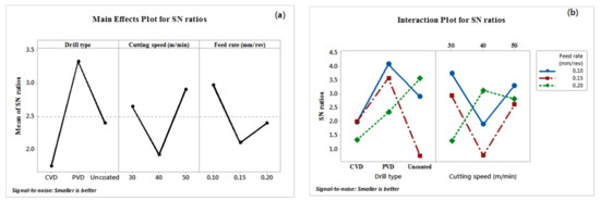
Figure 12.
(a) Plot of the main effects for the S/N ratio; and (b) interaction plot for S/N ratios of surface roughness for (Mg/10 wt %SiC/0.25 wt %GNPs) MMC.
3.4. Drilled Surfaces SEM Investigation
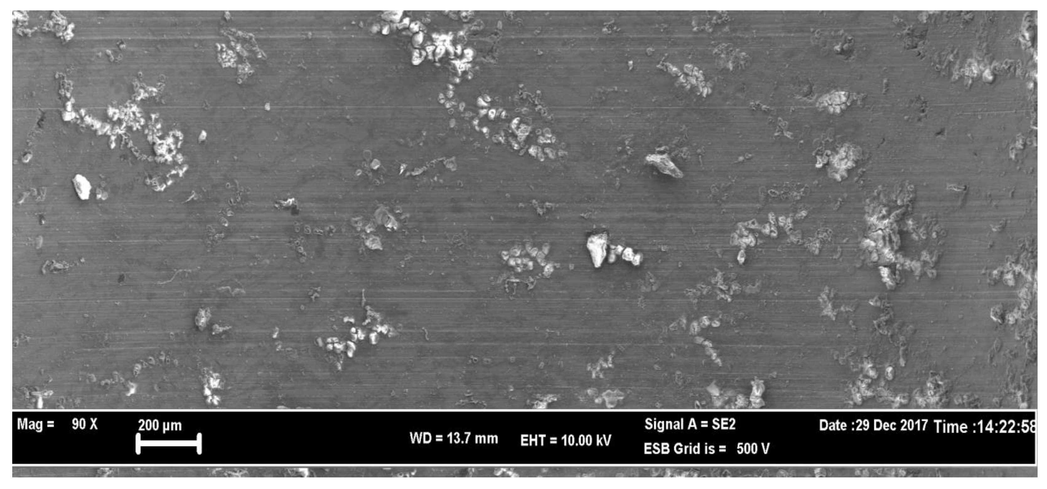
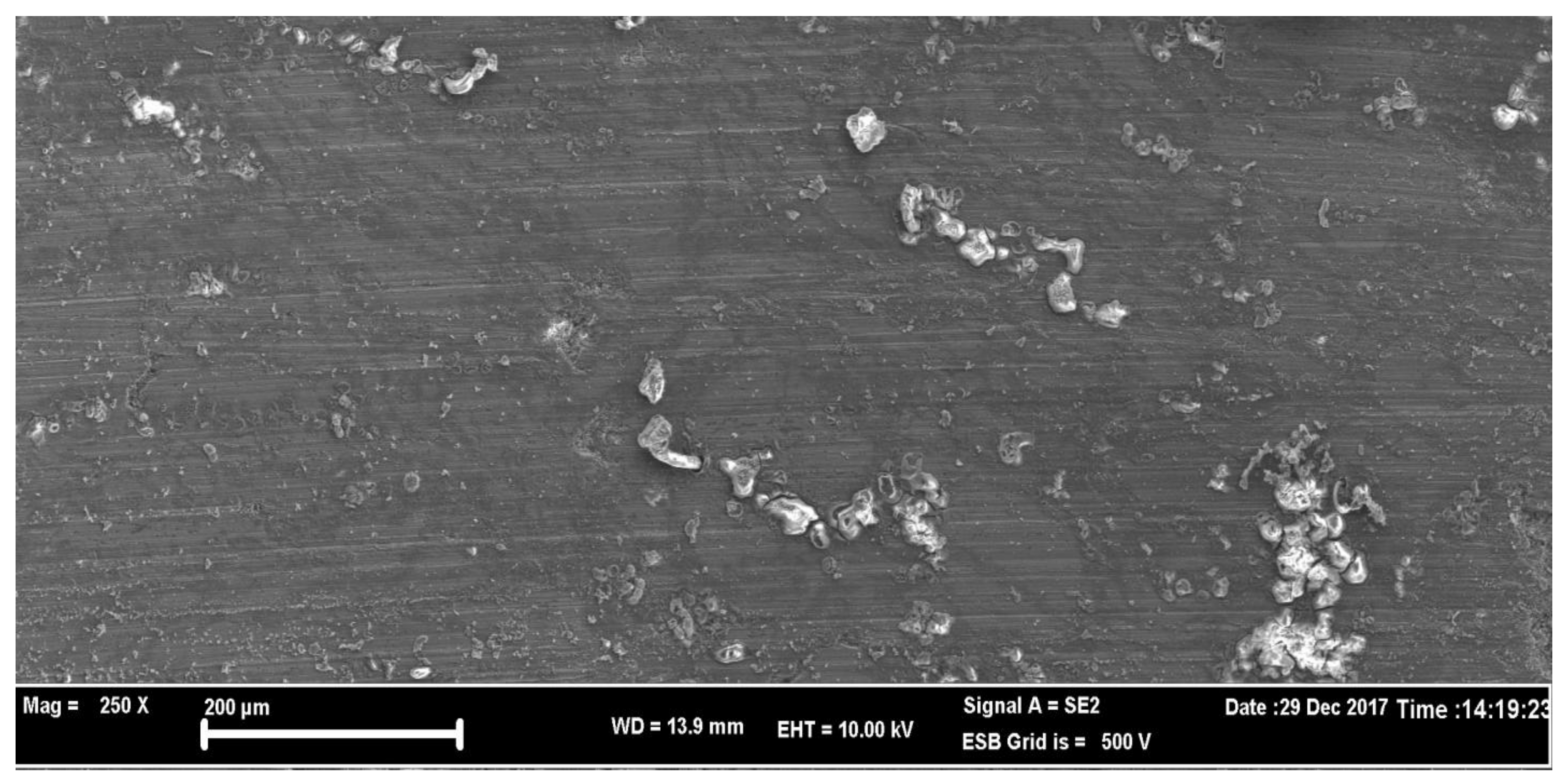
Scanning electron microscopy (SEM) was used to monitor and examine the drilled surfaces. A high feed rate causes comprehensive surface damage due to a high contact pressure, and fine grooves and cracks are observed, caused by the strain hardening of the Mg matrix material [18]. Figure 13 shows the SEM image of the drilled surface at Vc = 50 m/min and f = 0.10 mm/rev while using the uncoated drill bit. The figure shows the scratches shaped in the vertical track during drilling, fine grooves, and BUE, which was due to the nature of the matrix material (Mg). Additionally, due to the heat generated during the drilling process, some oxidation layers appeared. It can be seen that the surface produced by uncoated drill bits was poor with fine grooves, which affected the surface quality in an adverse manner.

Figure 13.
(a) SEM image of the drilled surface at Vc = 50 m/min and f = 0.10 mm/rev when using the uncoated drill bit; and (b) SEM image of selected area 1 with 250× magnification.
The SEM image of the drilled surface while using the PVD coated drill bit at Vc = 30 m/min and f = 0.20 mm/rev is presented in Figure 14. The hole drilled surface is smoother with some amount of BUE, which is because of the tough layer coating (TiN) the drill bit’s surface, which reduces the BUE phenomenon.
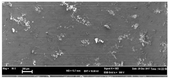
Figure 14.
SEM image of the drilled surface at Vc = 30 m/min and f = 0.20 mm/rev when using the PVD-coated drill bit.
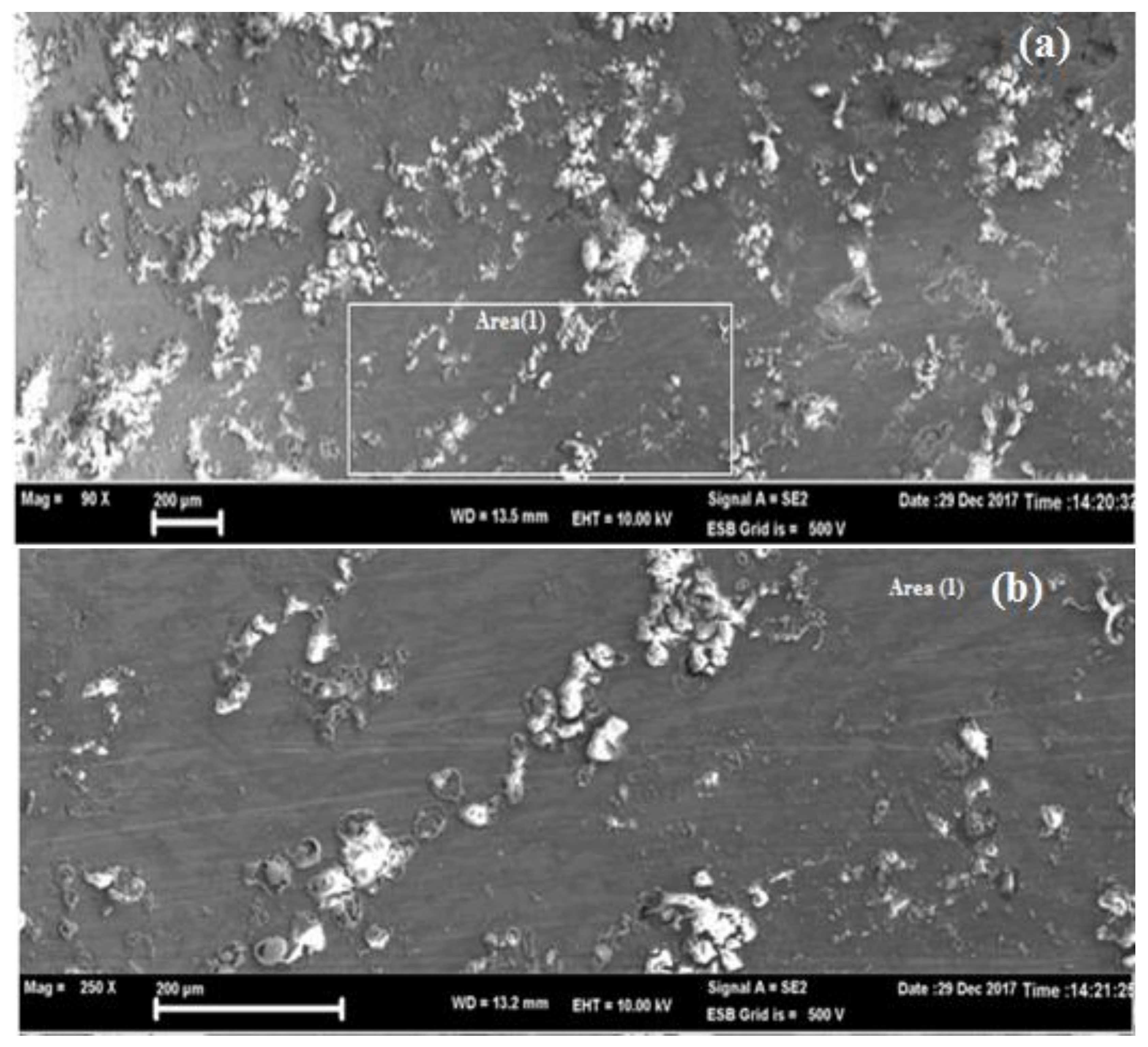
Figure 15 shows the SEM image of the drilled surface at Vc = 50 m/min and f = 0.10 mm/rev while using the CVD-coated drill bit, the feed mark was clearly visible on the drilled surface of the MMC, with a small amount of BUE, fine grooves, and scratches.

Figure 15.
SEM image of the drilled surface at Vc = 50 m/min and f = 0.10 mm/rev when using the CVD-coated drill bit.
The careful observation of the drilled surface showed that the removed SiC particles rubbed on the drilled surface causing scratches. Micro-cracks formed due to the strain hardening of the matrix material (Mg). Generally, the performance of coated drill bits is better compared to the uncoated drill bits at the different feed rates and cutting speeds used in this investigation study [6,19]. However, coated drill bits show the smoother machined surfaces, and uncoated drill bits present additional BUE than the coated drill bits, which participate to coarsely-drilled surfaces.
4. Conclusions
The drilling process for reinforced hybrid Mg matrix composites Mg/10 wt %Sic/0.25 wt %GNPs was investigated. The investigation of the effects of cutting speed, feed rate and the types of drill bits on the thrust force, the surface roughness, and the drilled surface characteristics during the drilling of the hybrid MMCs. The following conclusion presents the results:
- The uniform distribution of GNPs and SiC reinforcements inside the grains of magnesium matrix was confirmed via SEM.
- Thrust force and surface roughness in the drilling of hybrid Mg MMC Mg/10 wt %SiC/0.25 wt %GNPs are highly dependent on the feed rate, cutting speed, and type of drill bits. In addition, they are dependent on the matrix material and reinforced elements composition, interface, and properties.
- The thrust force is increased by increasing the feed rate, while the thrust force decreases with the increase of the cutting speed. The highest thrust forces were reached at lower cutting speed when using uncoated drill bits. However, with the PVD-coated drill bits, the lowest thrust force was reached at the cutting speed of 50 m/min with the three levels of feed rates.
- Taguchi statistical analysis shows that the most significant parameters that affect the thrust force are the type of drill, followed by the cutting speed and the feed rate. The optimal parameters combination to reach the minimum value of thrust force are the PVD coated drill bit, the cutting speed of 50 m/min, and feed rate of 0.10 mm/rev.
- The surface roughness (Ra) values of drilled surfaces are lower during the usage of coated drill bits. This is due to the hard coating over the drill bit surfaces, which reduced the BUE formation during drilling. The higher value is obtained during the use of uncoated drill bits at a cutting speed of 40 m/min and a 0.15 mm/rev feed rate. The results specify that lower feed rates are preferred in the drilling of hybrid Mg/SiC/GNPs MMC. The increase in the feed rate increases the thrust force and this affects the surface finish.
- Taguchi statistical analysis shows the most significant parameters that affect the surface roughness (Ra) are the type of drill, followed by the cutting speed and then the feed rate.
- The surfaces produced by using the uncoated drill bits is poor in quality, with fine grooves affecting the surface finish, and the performance of the coated drill bits is better compared to the uncoated drill bits at the different feed rates and cutting speeds were used in this investigation study.
- The hole drilled surface is smoother and flatter with some amount of BUE when using the PVD- and the CVD-coated drill bits, this is because of the hard coating layer (TiN and AlTiN) which reduces the BUE phenomenon.
Acknowledgments
The authors would express their gratitude to Gultekin Uzun and Bahattin Yilmaz at Gazi University for their assistance during the experimental work.
Author Contributions
Mustafa M. Abdulgadir and Muhammet Emre Turan designed the tests, performed the tests, analyzed the data, and wrote the paper. Bilge Demir directed the research and contributed to the discussion of the results.
Conflicts of Interest
The authors declare no conflict of interest.
References
- Li, X.P.; Lu, L. Study of the reinforcement percentage of Mg-Al-SiC MMC in relation to the mechanical properties and machinability. In Materials Science Forum; Trans Tech Publications Ltd.: Zurich-Uetikon, Switzerland, 2003; Volume 437, pp. 185–188. [Google Scholar] [CrossRef]
- Rajmohan, T.; Palanikumar, K.; Kathirvel, M. Optimization of machining parameters in drilling hybrid aluminium metal matrix composites. Trans. Nonferrous Met. Soc. China 2012, 22, 1286–1297. [Google Scholar] [CrossRef]
- Sahin, Y.; Sur, G. The effect of Al2O3, Ti(C, N) based CVD coatings on tool wear in machining metal matrix composites. Surf. Coat. Technol. 2004, 179, 349–355. [Google Scholar] [CrossRef]
- Jiang, Q.C.; Li, X.L.; Wang, H.Y. Fabrication of TiC particulate reinforced magnesium matrix composites. Scr. Mater. 2003, 48, 713–717. [Google Scholar] [CrossRef]
- Rashad, M.; Pan, F.; Tang, A.; Asif, M.; Hussain, S.; Gou, J.; Mao, J. Improved strength and ductility of magnesium and graphenenanoplatelets using semi powder metallurgy method. J. Ind. Eng. Chem. 2015, 23, 243–250. [Google Scholar] [CrossRef]
- Weinert, K.; Lange, M. Machining of magnesium matrix composites. Adv. Eng. Mater. 2001, 3, 975–979. [Google Scholar] [CrossRef]
- Morin, E.; Masounave, J.; Laufer, E.E. Effect of drill wear on cutting forces in the drilling of metal-matrix composites. Wear 1995, 184, 11–16. [Google Scholar] [CrossRef]
- Gupta, M.; Wong, W.L.E. Magnesium-based nano composites: Lightweight materials of the future. Mater. Charact. 2015, 105, 30–46. [Google Scholar] [CrossRef]
- Rashad, M.; Pan, F.; Asif, M. Magnesium matrix composites reinforced with Graphene Nanoplatelets. In Graphene Materials: Fundamentals and Emerging Applications; John Wiley & Sons: Hoboken, NJ, USA, 2015; pp. 151–189. [Google Scholar]
- Rashad, M.; Pan, F.; Tang, A.; Asif, M.; She, J.; Gou, J.; Mao, J.; Hu, H. Development of magnesium graphenenanoplatelets composite. J. Compos. Mater. 2015, 49, 285–293. [Google Scholar] [CrossRef]
- Rashad, M.; Pan, F.; Tang, A.; Lu, Y.; Asif, M.; Hussain, S.; She, J.; Gou, J.; Mao, J. Effect of graphenenanoplatelets addition on strength and ductility of magnesium-titanium alloys. J.Magnes. Alloy. 2013, 1, 242–248. [Google Scholar] [CrossRef]
- Saravananakumar, M.; Natarajan, N.; Krishnaraj, V. Study of cutting forces in machining of magnesium composite by response surface methodology. Carbon Sci. Technol. 2015, 7, 36–58. [Google Scholar]
- Raj, A.M.; Das, S.L.; Palanikumarr, K. Influence of drill geometry on surface roughness in drilling of Al/SiC/Gr hybrid metal matrix composite. Indian J. Sci. Technol. 2013, 6, 5002–5007. [Google Scholar]
- Anthony, X.M.; Kumar, A.J.P. Machinability of hybrid metal matrix composite-A review. Procedia Eng. 2017, 174, 1110–1118. [Google Scholar]
- Palanikumar, K.; Muniaraj, A. Experimental investigation and analysis of thrust force in drilling cast hybrid metal matrix(Al-SiC-graphite) composites. Measurement 2014, 53, 240–250. [Google Scholar] [CrossRef]
- Sekhar, R.; Singh, T.P. Mechanisms in turning of metal matrix composites: A review. J. Mater. Res. Technol. 2015, 4, 197–207. [Google Scholar] [CrossRef]
- Nicholls, C.J.; Boswell, B.; Davies, I.J.; Islam, M.N. Review of machining metal matrix composites. Inter. J. Adv. Manuf. Technol. 2017, 90, 2429–2441. [Google Scholar] [CrossRef]
- Teng, X.; Huo, D.; Wong, E.; Meenashisundaram, G.; Gupta, M. Micro-machinability of nanoparticle-reinforced Mg-based MMCs: An experimental investigation. Inter. J. Adv. Manuf. Technol. 2016, 87, 2165–2178. [Google Scholar] [CrossRef]
- Pedersen, W.; Ramulu, M. Facing SiCp/Mg metal matrix composites with carbide tools. J. Mater. Process. Technol. 2006, 172, 417–423. [Google Scholar] [CrossRef]
© 2018 by the authors. Licensee MDPI, Basel, Switzerland. This article is an open access article distributed under the terms and conditions of the Creative Commons Attribution (CC BY) license (http://creativecommons.org/licenses/by/4.0/).