Experimental Study for Improving the Repair of Magnesium–Aluminium Hybrid Parts by Turning Processes


Abstract
1. Introduction
2. Methodology
- ▪
- Pre-experimental planning. Factors, levels, ranges, and response variables are set up.
- ▪
- Selection of the experimental design. At this stage, the most adequate design of experiments (DOE) is selected according to the available resources and the objectives fixed in the study. In this case, the goal is to analyze the variability of the surface roughness of hybrid parts with a UNS M11917 magnesium alloy base and with two UNS A92024 aluminium alloy inserts obtained by turning. The surface roughness has been chosen as a response variable and, specifically, the arithmetic mean deviation of the assessed profile, Ra, because it is one of the most widely used variables in the literature and it allows for a better comparison with other studies on this theme. The process is to be performed with different types of tools, different cutting conditions, and under dry conditions, so that the potential influential factors to include in the design have been identified as: depth of cut, d; feed rate, f; spindle speed, S; and type of tool, T. In addition, the Ra values are taken on different zones of the workpieces, since previous studies [47,48,49,50,51,52,53] have found that the location where the surface roughness measurement was taken seemed to influence the value of the surface roughness. Now, there are two positions where the response variable is measured in the specimen: the location with respect to the specimen, LRS, and the position where the response variable is measured with respect to the insert, LRI. Their levels are fixed, taking into account the following criteria:
- -
- First, the work is framed within a study involving other types of hybrid parts based on magnesium, but using different types of materials for the inserts used. Then, it seems reasonable to try, at least, two types of tools: one that is suitable for magnesium and other non-ferrous alloys, and another for other types of materials. Thus, it could be known how these tools behave with these materials and with others separately, to see if they can then be used in applications involving all types of materials. That is, two levels should be established for the factor, type of tool, T.
- -
- Second, as the study deals with repair and maintenance operations, in general, the depth of cut, d, has to be as small as the available machines allow, since, otherwise, the parts could be out of dimensional tolerances. Then, one level is enough.
- -
- Third, for the factors feed rate, f, and spindle speed, S, which are expected to have influences on the study (in particular the feed rate), two levels for each one are fixed.
- -
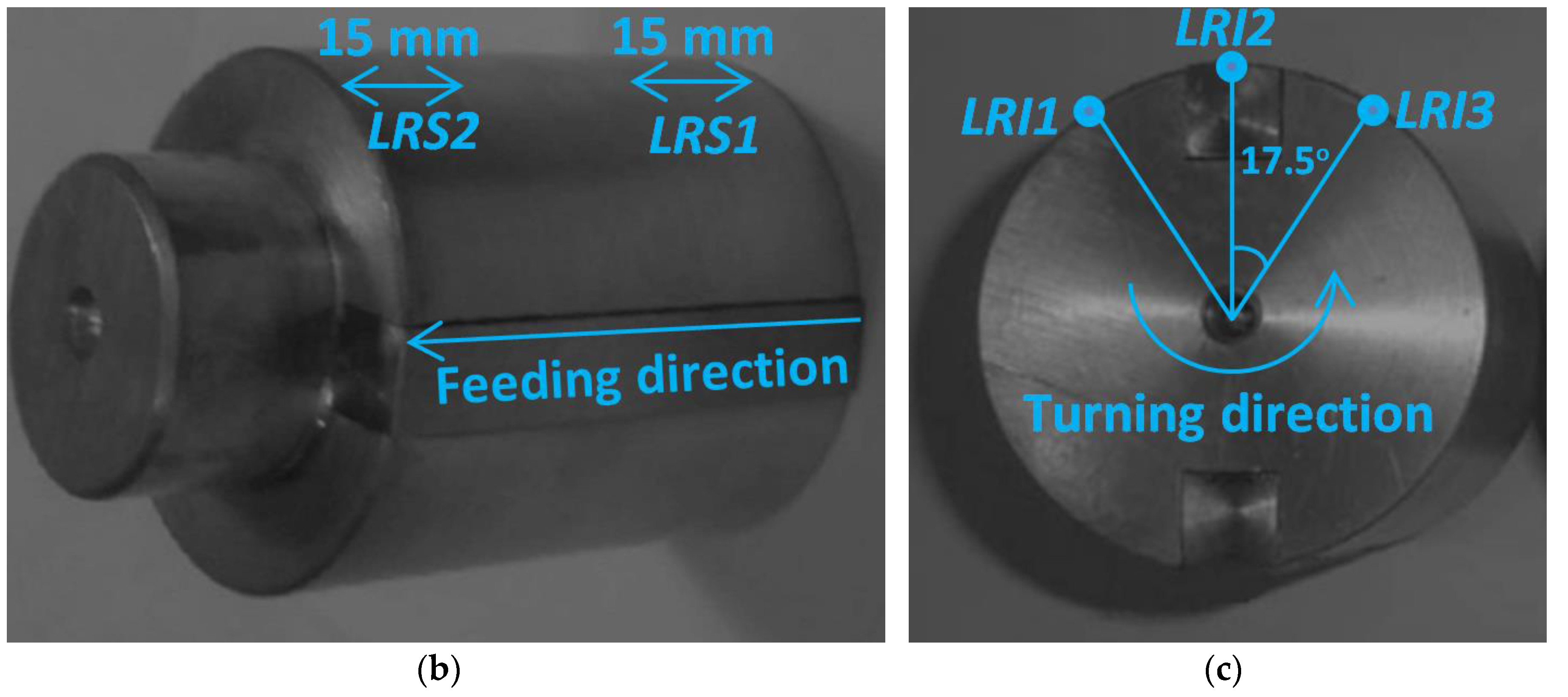
- Finally, as has been mentioned above, previous studies seem to indicate that the roughness can vary with the length of machining of the piece. Therefore, LRS and LRI are going to be taken into account as influencing factors. Specifically, two levels for LRS and three levels for LRI will be established. That is, surface roughness measurements will be taken: for LRS, following the feeding direction, at the beginning of the specimen, LRS1, and at the end of the specimen, LRS2; and for LRI, according to the turning direction, before the insert, LRI1, in the insert, LRI2, and after the insert, LRI3. Table 1 shows the factors and levels fixed for them and their designations.
- ▪
- Performing the experiment. As this work is framed within a larger project, the execution of the tests has been programmed to be carried out systematically following the next steps:
- -
- Previous activities to the machining process. These activities consist in preparing: the specimens of the hybrid parts, the tools, the protocols to be used to calculate the cutting parameters’ values that will be introduced into the machine, the instrument where the surface roughness measurements will be taken, and the protocols to register the obtained data.
- -
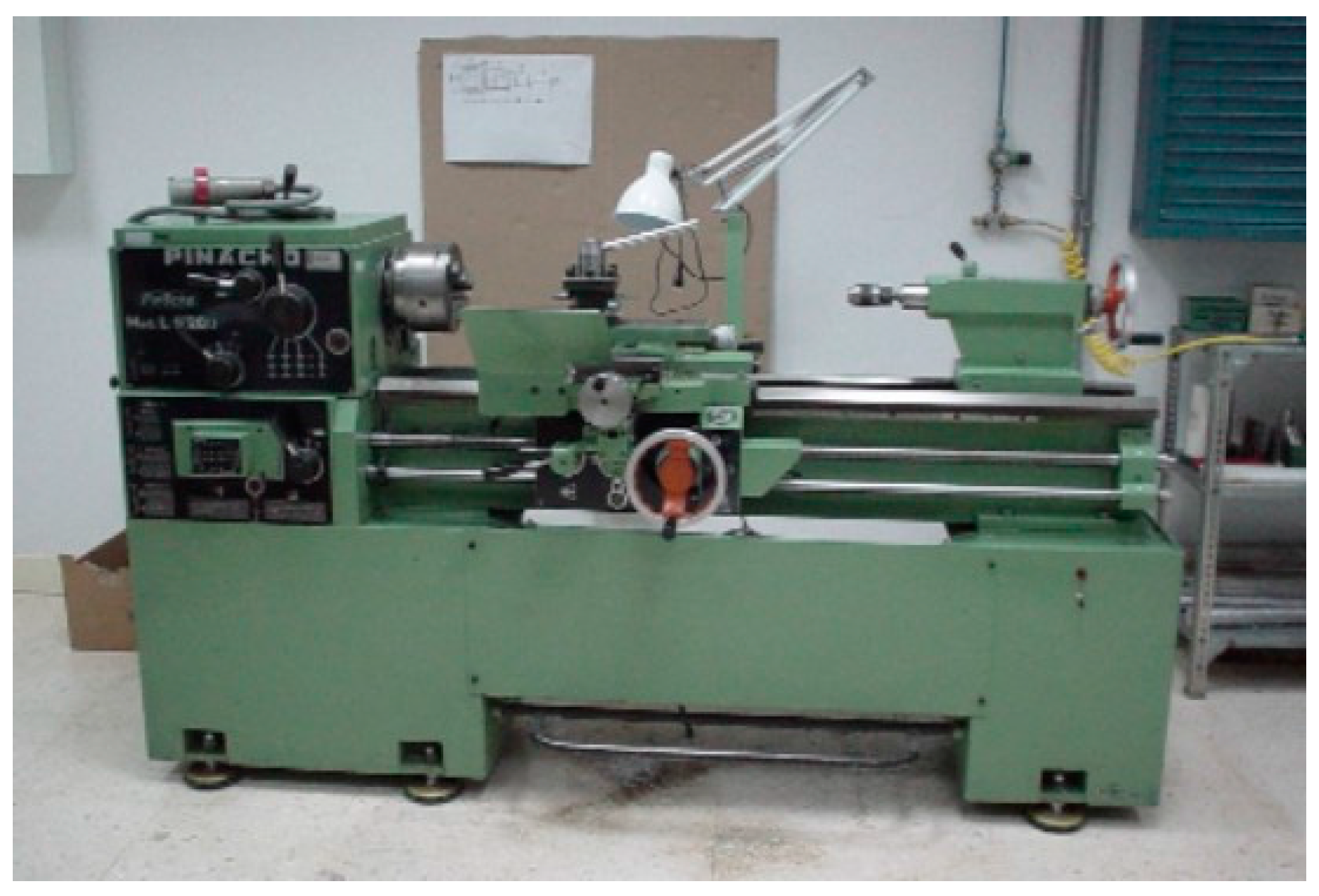
- Turning trials. During the trials, specimens are mechanized under the cutting conditions determined for them.
- -
- Monitoring processes. All of the turning trials described previously along with the obtained chips and used tools were photographed and recorded by video with a Hero Silver 4 high-resolution camera (GOPRO Inc., San Mateo, CA, USA) in order to have graphical documents that can be analysed once the process has finished.
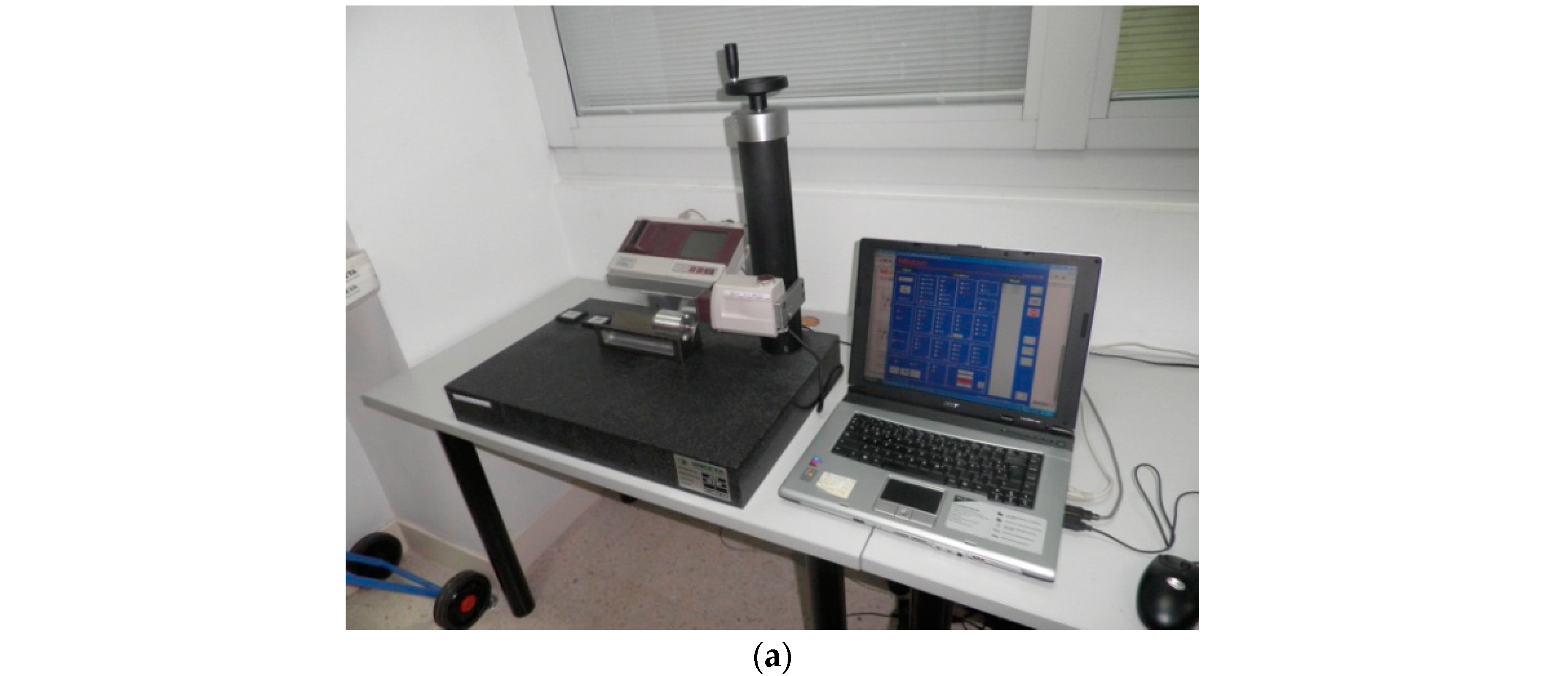
- ▪
- Roughness measurement. Measurements of the surface roughness are made using a Mitutoyo Surftest SJ 401 surface roughness tester (Mitutoyo America Corporation, Aurora, IL, USA).
- ▪
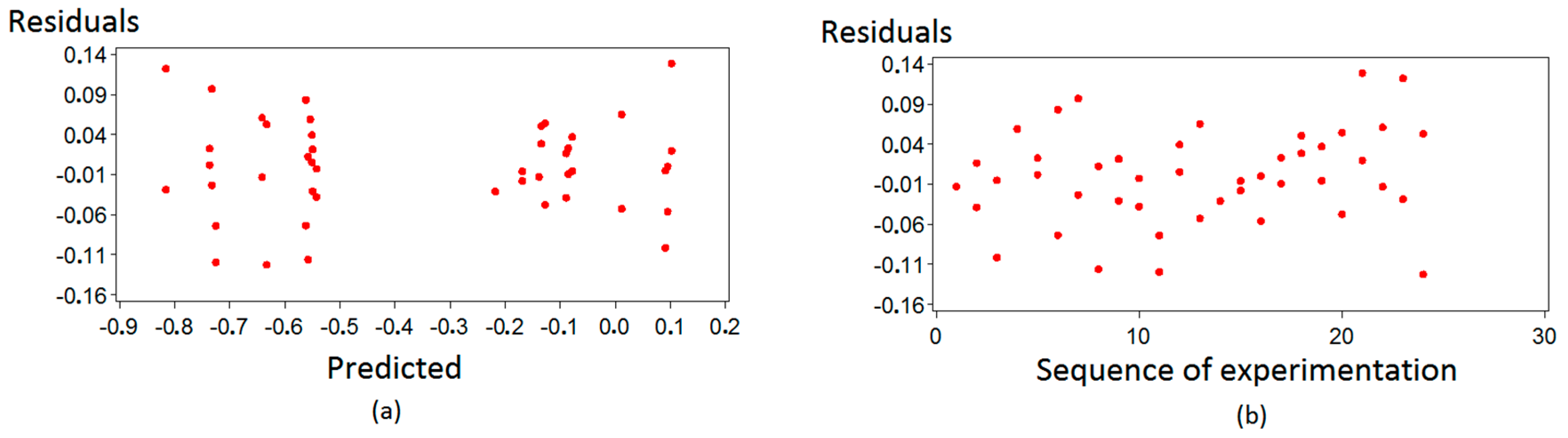
- Statistical analysis of the data. The statistical methodology carried out in order to analyze the results of the experimental design is briefly described in [54]. The variability of the surface roughness is modelled through the analysis of variance (ANOVA) over the average roughness values, Ra, identifying the most influential factors and interactions on the surface finish. The model hypothesis is checked, and the ranking of the different combinations of the process parameters’ levels is obtained based on the roughness values predicted by the model. The optimal combination of cutting conditions (minimum expected roughness) is selected from such ranking. In addition, we conduct an exploratory data analysis to obtain a clear graphical view of the key aspects in the distribution of the influential factors on the surface finish of hybrid magnesium–aluminum parts, and relationships between pairs of influential factors have been illustrated by interaction graphs.
- ▪
- Conclusions. Some conclusions are established from the results obtained in the statistical analysis.
3. Experimental Tests
3.1. Materials
- ▪
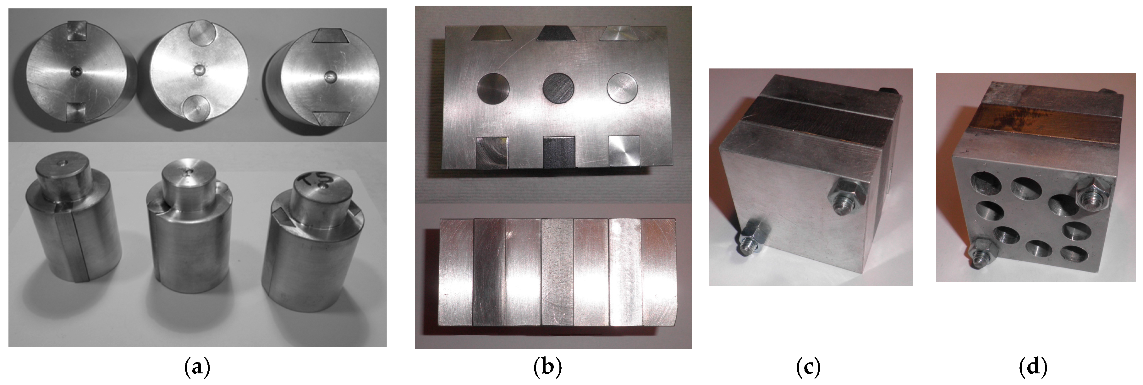
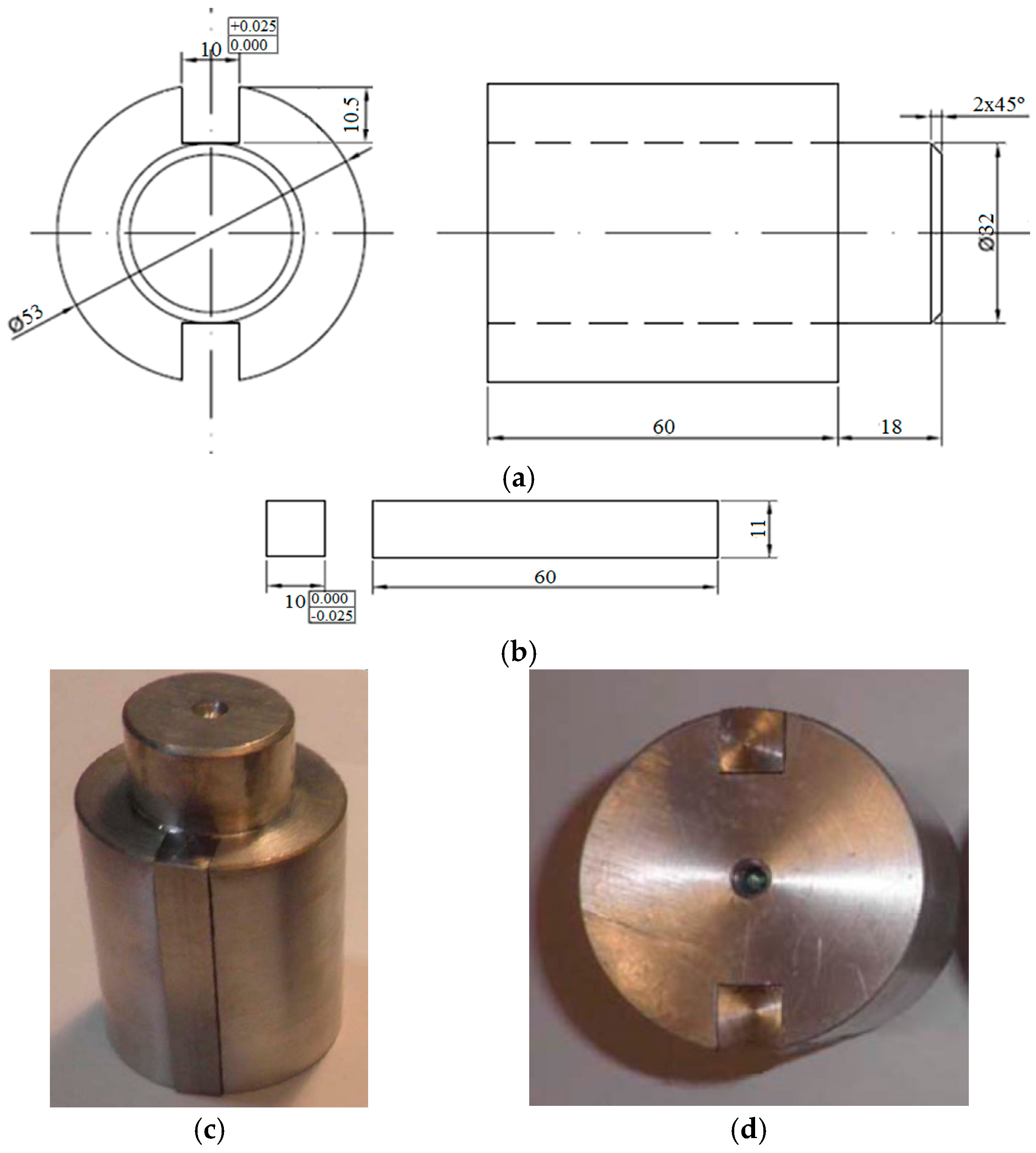
- In the absence of standards, national or international, or any other reference in relation to the design and fabrication of test pieces of metal hybrid components, such as those presented in this work, it was decided to start the study with different simple geometries for both the base and for the inserts, since, on many occasions, the repair and maintenance operations are limited to a small area of the surface of the piece and, therefore, the geometry to be machined is reduced to simple forms, such as those proposed in the general project regardless of the overall complexity of the piece [20,45]. On the other hand, this approach would allow, if necessary, for an increase in the degree of complexity of the geometry of the test pieces from solid knowledge about the joint behaviour of the individual materials depending on the results that were obtained.
- ▪
- We have previous experience in the machining of both materials, both in continuous turning (horizontal and facing) [47,48,49,50,51,52,53,54,55,56,57,58,59,60] and in intermittent turning [56,57,58,59,60]. The geometry of the specimens raised in the present study is a natural evolution of the geometries and materials previously studied separately that have just been mentioned.
- ▪
- ▪
3.2. Cutting Tools
3.3. Cutting Conditions
3.4. Measurement Locations
3.5. Factors and Levels Selected
4. Results, Analysis, and Discussion
4.1. Results
- ▪
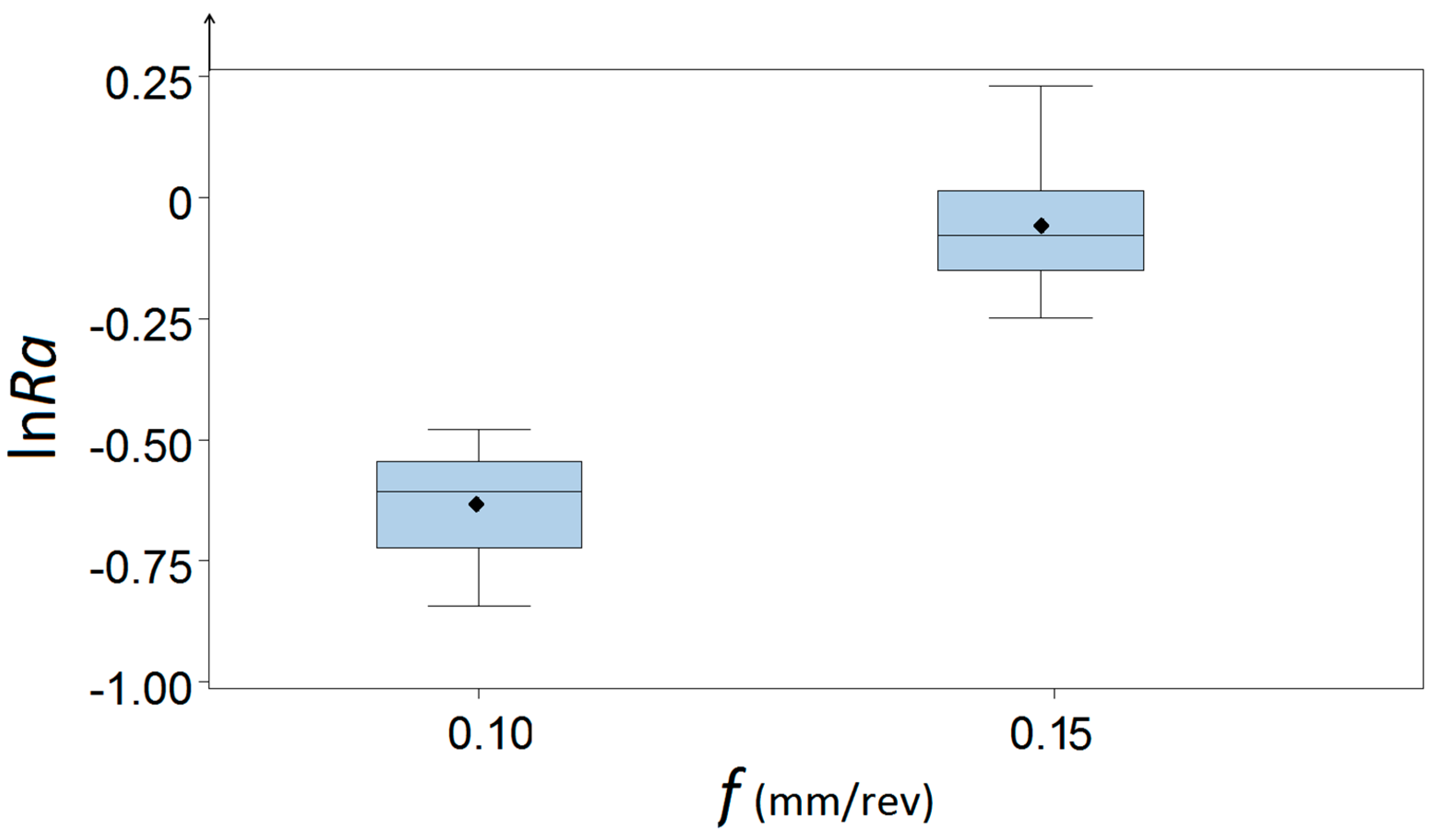
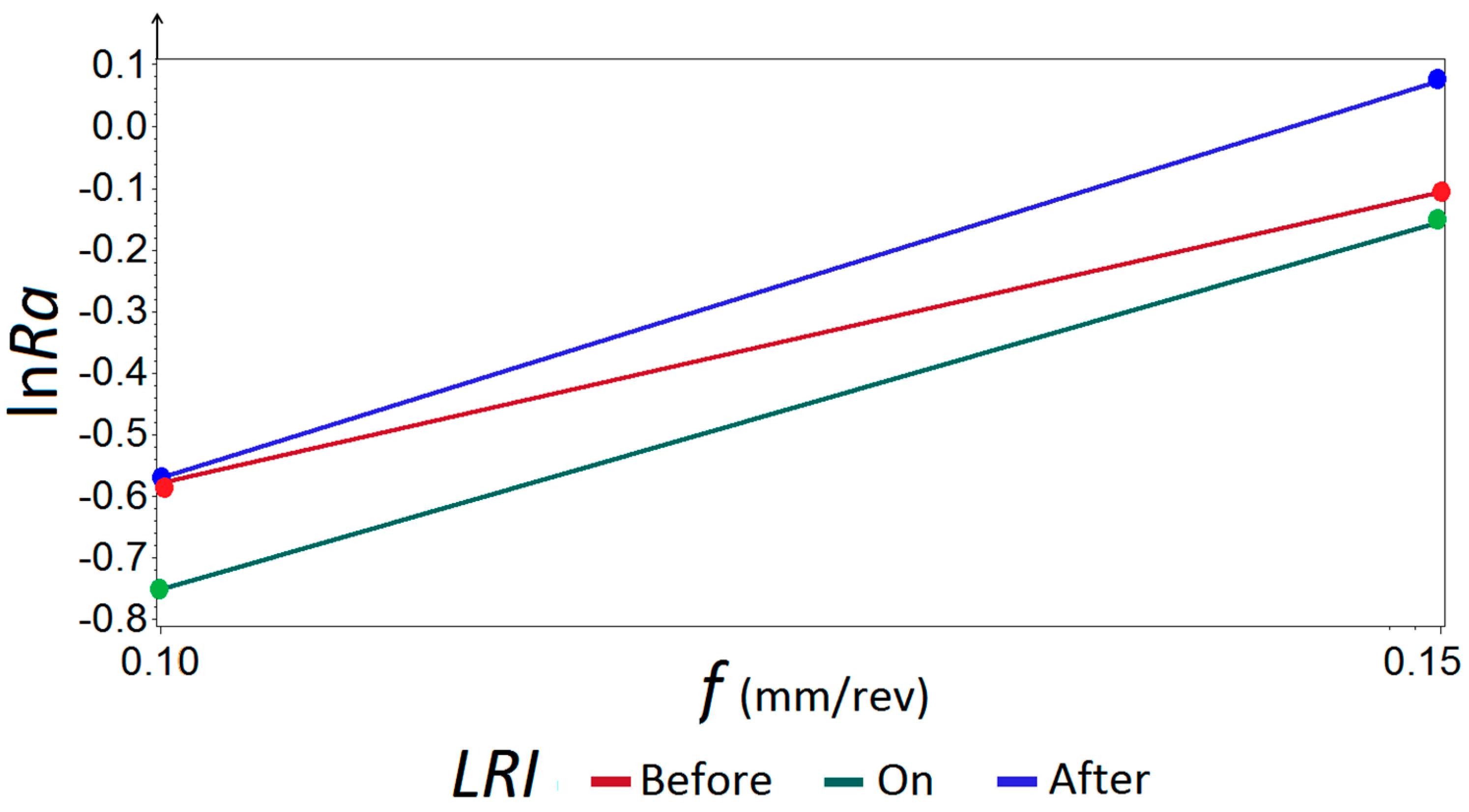
- In relation to the feed rate, the values of the roughness increase in the three measured zones. Specifically, for f = 0.10 mm/rev, the mean values of the roughness are RaLRI1 = 0.57 μm; RaLRI2 = 0.48 μm; and RaLRI3 = 0.57 μm, and for f = 0.15 mm/rev, the mean values of the roughness are RaLRI1 = 0.91 μm; RaLRI2 = 0.86 μm; and RaLRI3 = 1.08 μm.
- ▪
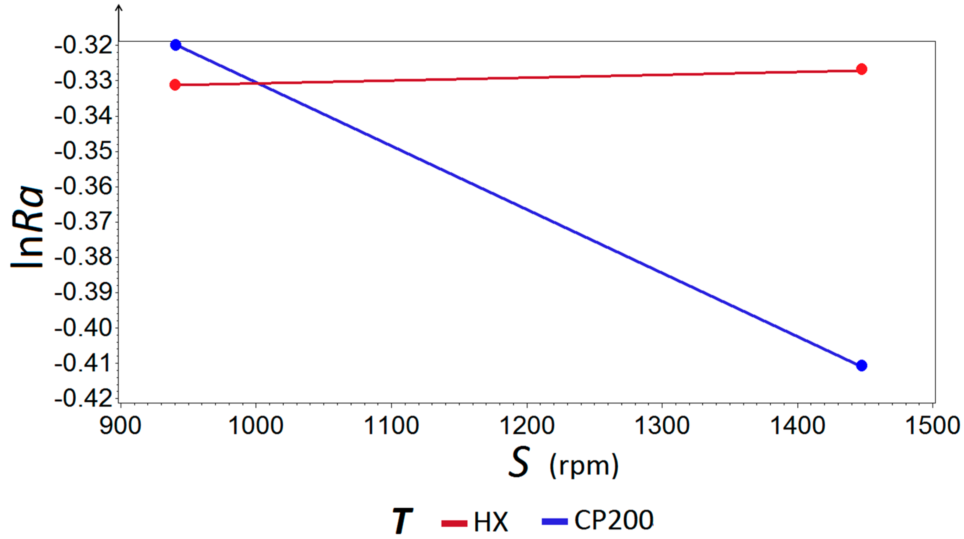
- With respect to the spindle speed, the values of Ra decrease slightly in the magnesium base and remain equal, or slightly increase, in the aluminum insert. Specifically, for S = 925 rpm, the mean values of the roughness are RaLRI1 = 0.76 μm; RaLRI2 = 0.67 μm; and RaLRI3 = 0.86 μm. For S = 1470 rpm, the mean values of the roughness are RaLRI1 = 0.72 μm; RaLRI2 = 0.67 μm; and RaLRI3 = 0.80 μm.
4.2. Statistical Discussion
4.3. Technological Discussion
5. Conclusions
Acknowledgments
Author Contributions
Conflicts of Interest
References
- Ashby, M.F.; Brécht, Y.J.M. Designing hybrid materials. Acta Mater. 2003, 51, 5801–5821. [Google Scholar] [CrossRef]
- Kickelbickm, G. Hybrid Materials. Synthesis, Characterization and Applications; Wiley-VCH Verlag GmbH & Co.: Darmstadt, Germany, 2007; ISBN 978-3-527-31299-3. [Google Scholar]
- Zakaria, B.; Yazid, H. Friction stir welding of disimilar materials Aluminum Al6061-T6 to ultra low carbon steel. Metals 2017, 7, 42. [Google Scholar] [CrossRef]
- Casalino, G. Advances in welding metal alloys, Disimilar metals and additively manufactured parts. Metals 2017, 7, 32. [Google Scholar] [CrossRef]
- Casalino, G.; Guglielmi, P.; Lorusso, V.D.; Mortello, M.; Peyre, P.; Sorgente, D. Lasser offset welding of AZ31B magnesium alloy to 316 stainless steel. J. Mater. Process. Technol. 2017, 242, 49–59. [Google Scholar] [CrossRef]
- Li, Y.; Liu, C.; Yu, H.; Zhao, F.; Wu, Z. Numerical simulation of Ti/Al bimetal composite fabricated by explosive welding. Metals 2017, 7, 407. [Google Scholar] [CrossRef]
- Cui, X.; Wang, S.; Hu, S.J. A method for optimal design of automotive body assembly using multi-material construction. Mater. Des. 2008, 29, 381–387. [Google Scholar] [CrossRef]
- Gururaja, M.N.; Rao, A.N.H. A review on recent applications and future prospectus of hybrid composites. Int. J. Soft Comput. Eng. 2012, 1, 352–355. [Google Scholar]
- Lee, D.; Morillo, C.; Oller, S.; Bugeda, G.; Oñate, E. Robust design optimization of advance hybrid (fiber-metal) composite structures. Compos. Struct. 2013, 99, 181–192. [Google Scholar] [CrossRef]
- DRL. Innovation Report 2011; Institute of Composites Structures and Adaptative Systems: Braunschweig, Germany, 2011. [Google Scholar]
- Wagner, F.; Zerner, I.; Kreimeyer, M.; Seefeld, T.; Sepold, G. Characterization and properties of dissimilar metal combinations of Fe/Al and Ti/Al sheet materials. In Proceedings of the ICALEO’01, Orlando, FL, USA, 15–18 October 2001. [Google Scholar]
- Luo, J.G.; Acoff, V.L. Interfacial reactions of titanium and aluminum during diffusion welding. Weld. J. 2000, 79, 239s–243s. [Google Scholar]
- Dau, J.; Lauter, C.; Damerow, U.; Homberg, W.; Tröster, T. Multi-material systems for tailored automotive structural components. In Proceedings of the 18th International Conference on Composite Materials, Jeju Island, Korea, 21–26 August 2011. [Google Scholar]
- Amancio, S. Innovative Solid-State Spot Joining Methods for Fiber Composites and Metal-Polymer Hybrid Structures; Joining in Car Body; Helmholtz-Zentrum Geesthacht: Geesthacht, Germany, 2012; pp. 1–47. [Google Scholar]
- Frantz, M.; Lauter, C.; Tröster, T. Advanced manufacturing technologies for automotive structures in multi-material design consisting of high-strength steels and CFRP. In Proceedings of the 56th International Scientific Colloquium, Ilmenau, Germany, 12–16 September 2011. [Google Scholar]
- Suryawanshi, B.K.; Prajitsen, G.D. Review of design of hybrid aluminum/composite drive shaft for automobile. Int. J. Innov. Technol. Explor. Eng. 2013, 2, 259–266. [Google Scholar]
- Uthayakumar, M.; Prabhaharan, G.; Aravindan, S.; Sivaprasad, J.V. Machining studies on bimetallic piston with CBN tool using the Taguchi method-technical communication. Mach. Sci. Technol. 2008, 12, 249–255. [Google Scholar] [CrossRef]
- Goede, M.; Stehlin, M.; Rafflenbeul, L.; Kopp, G.; Beeh, E. Super light car: Lightweight construction thanks to a multi-material design and functional integration. Eur. Transp. Res. Rev. 2009, 1, 5–10. [Google Scholar] [CrossRef]
- Ben-Artzy, A.; Munitz, A.; Kohn, G.; Bronfin, B.; Shtechman, A. Joining of light hybrid constructions made of magnesium and aluminum alloys. Magn. Technol. 2002, 295–302. [Google Scholar] [CrossRef]
- Sáenz de Pipaón, M.J. Diseño y Fabricación de Probetas de Componentes Híbridos con Aleaciones de Magnesio para Ensayos de Mecanizado. Ph.D. Thesis, UNED (Universidad Nacional de Educación a Distancia), Madrid, Spain, 2013. [Google Scholar]
- Qi, X.; Song, G. Interfacial structure of the joints between magnesium alloy and mild steel with nickel as interlayer laser-TIG welding. Mater. Des. 2010, 31, 605–609. [Google Scholar] [CrossRef]
- Nasiri, A.M.; Li, L.; Kim, S.H.; Zhou, Y.; Weckman, D.C.; Nguyen, T.C. Microstructure and properties of laser brazed magnesium to coated steel. Weld. J. 2011, 90, 211s–219s. [Google Scholar]
- Nasiri, A.M.; Weckman, D.C.; Zhou, Y. Interfacial microstructure of diode laser brazed AZ31B magnesium to steel sheet using a nickel interlayer. Weld. J. 2013, 92, 1–10. [Google Scholar]
- Krebs, R.; Böhme, J.; Doerr, J.; Rothe, A.; Schneider, W.; Haberling, C. Magnesium, hybrid turbo engine from Audi. MTZ Worldw. 2005, 66, 13–16. [Google Scholar] [CrossRef]
- Fischersworring-Bunk, A.; Landerl, C.; Fent, A.; Wolf, J. The new BMW inline six-cylinder composite Mg/Al crankcase. In Proceedings of the IMA 05, 62nd Annual World Magnesium Conference, Berlin, Germany, 22–24 May 2005. [Google Scholar]
- Carou, D.; Rubio, E.M.; Davim, J.P. Analysis of ignition risk in intermittent turning of UNS M11917 magnesium alloy at low cutting speeds based on the chip morphology. Proc. Inst. Mech. Eng. Part B J. Eng. Manuf. 2015, 229, 365–371. [Google Scholar] [CrossRef]
- Sáenz de Pipaón, M.J.; Rubio, E.M.; Villeta, M.; Sebastián, M.A. Influence of cutting conditions and tool coatings on the surface finish of workpieces of magnesium obtained by dry turning. In Proceedings of the 19th International DAAAM Symposium, Trnava, Slovakia, 22–25 October 2008; pp. 604–605. [Google Scholar]
- Bisker, J.; Christman, T.; Allison, T.; Goranson, H.; Landmesser, J.; Minister, A.; Plonski, R. DOE Handbook, Primer on Spontaneous Heating and Pyrophoricity; U.S. Department of Energy: Washington, DC, USA, 1994; pp. 1–68. [Google Scholar]
- NanoMAG. Hydro Magnesium’s Machining Magnesium; Technical Document; NanoMAG: Livonia, MI, USA, 2009; Available online: http://nanomag.us (accessed on 22 November 2017).
- Rubio, E.M.; Sáenz de Pipaón, M.J.; Villeta, M.; Sebastián, M.A. Experimental study for improving repair operations of pieces of magnesium UNS M11311 obtained by dry turning. In Proceedings of the 12th CIRP Conference on Modelling of Machining, San Sebastian, Spain, 7–8 May 2009; pp. 819–826. [Google Scholar]
- Carou, D.; Rubio, E.M.; Davim, J.P. Discontinuous cutting: Failure mechanisms, tools materials and temperature study—A review. Rev. Adv. Mater. Sci. 2014, 38, 110–124. [Google Scholar]
- Rubio, E.M.; de Agustina, B.; Marín, M.M.; Bericua, A. Cooling systems based on cold compressed air: A review of the applications in machining processes. Proc. Eng. 2015, 132, 413–418. [Google Scholar] [CrossRef]
- Carou, D.; Rubio, E.M.; Davim, J.P. A note on the use of the minimum quantity lubrication (MQL) system in turning. Ind. Lubr. Tribol. 2015, 67, 256–261. [Google Scholar] [CrossRef]
- Arokiadass, R.; Palaniradja, K.; Alagumoorthi, N. Effect of process parameters on surface roughness in end milling of Al/SiCp MMC. Int. J. Eng. Sci. Technol. 2011, 13, 276–284. [Google Scholar]
- Carou, D.; Rubio, E.M.; Lauro, J.P.; Davim, J.P. Experimental investigation on surface finish during intermittent turning of UNS M11917 magnesium alloy under dry and near dry machining conditions. Measurement 2014, 56, 136–154. [Google Scholar] [CrossRef]
- Carou, D.; Rubio, E.M.; Lauro, J.P.; Davim, J.P. Experimental investigation on finish intermittent turning of UNS M11917 magnesium alloy under dry machining. Int. J. Adv. Manuf. Technol. 2014, 75, 1417–1429. [Google Scholar] [CrossRef]
- Ozsváth, P.; Szmejkál, A.; Takács, J. Dry milling of magnesium based hybrid materials. Transp. Eng. 2008, 36, 73–78. [Google Scholar] [CrossRef]
- Prakash, S.; Palanikumar, K.; Mercy, J.L.; Nithyalakshmi, S. Evaluation of surface roughness parameters (Ra, Rz) in drilling of MDF composite panel using Box-Behnken experimental design (BBD). Int. J. Des. Manuf. Technol. 2011, 5, 52–62. [Google Scholar]
- Rubio, E.M.; Valencia, J.L.; Saá, A.J.; Carou, D. Experimental study of the dry facing of magnesium pieces based on the surface roughness. Int. J. Precis. Eng. Manuf. 2013, 14, 995–1001. [Google Scholar] [CrossRef]
- Rubio, E.M.; Villeta, M.; Carou, D.; Saá, A.J. Comparative analysis of sustainable cooling systems in intermittent turning of magnesium pieces. Int. J. Precis. Eng. Manuf. 2014, 15, 929–940. [Google Scholar] [CrossRef]
- Rubio, E.M.; Valencia, J.L.; de Agustina, B.; Saá, A.J. Tool selection based on surface roughness in dry facing repair operations of magnesium pieces. Int. J. Mater. Prod. Technol. 2014, 48, 116–134. [Google Scholar] [CrossRef]
- Sáenz de Pipaón, J.M.; Rubio, E.M.; Villeta, M.; Sebastián, M.A. Analysis of the chips obtained by dry turning of UNS M11311 magnesium. In Proceedings of the 3rd Manufacturing Engineering Society International Conference 2009, Alcoy, Spain, 17–19 June 2009; pp. 33–38. [Google Scholar]
- Sáenz de Pipaón, J.M.; Rubio, E.M.; Villeta, M.; Sebastián, M.A. Selection of the cutting tools and conditions for the low speed turning of bars of magnesium UNS M11311 based on the surface roughness. In Innovative Production Machines and Systems; Whittles Publishing: Scotland, UK, 2010; pp. 174–179. ISBN 978-184995-006-0. [Google Scholar]
- Villeta, M.; Rubio, E.M.; Sáenz de Pipaón, J.M.; Sebastián, M.A. Surface finish optimization of magnesium pieces obtained by dry turning based on Taguchi techniques and statistical test. Mater. Manuf. Process. 2011, 26, 1503–1510. [Google Scholar] [CrossRef]
- Rubio, E.M.; Sáenz de Pipaón, J.M.; Valencia, J.L.; Villeta, M. Design, Manufacturing and Machining Trials of Magnesium Based Hybrid Parts, Machining of Light Alloys: Aluminium, Titanium and Magnesium; CRC-Press: Boca Raton, FL, USA, 2018; under review. [Google Scholar]
- Montgomery, D.C. Design and Analysis of Experiments; John Wiley & Sons, Inc.: New York, NY, USA, 2005. [Google Scholar]
- Rubio, E.M.; Camacho, A.M.; Sánchez, J.M.; Marcos, M. Surface roughness of AA7050 alloy turned bars, analysis of the influence of the length of machining. J. Mater. Process. Technol. 2005, 162–163, 682–689. [Google Scholar] [CrossRef]
- Batista, M.; Sánchez-Carrilero, M.; Rubio, E.M.; Marcos, M. Cutting Speed and Feed Based Analysis of Chip Arrangement in the Dry Horizontal Turning of UNS A92024 Alloy; Annals of the DAAAM for 2009; DAAAM International: Vienna, Austria, 2009; Volume 20, pp. 967–968. ISBN 978-3-901509-70-4. [Google Scholar]
- Saá, A.J.; Agustina, B.; Marcos, M.; Rubio, E.M. Experimental study of dry turning of UNS A92024-T3 aluminium alloy bars based on surface roughness. AIP Conf. Proc. 2009, 1181, 151–158. [Google Scholar]
- Agustina, B.; Saá, A.; Marcos, M.; Rubio, E.M. Analysis of the machinability of aluminium alloys UNS A97050-T7 and UNS A92024-T3 during short dry turning tests. Adv. Mater. Res. 2011, 264–265, 931–936. [Google Scholar] [CrossRef]
- Agustina, B.; Rubio, E.M. Experimental study of cutting forces during dry turning processes of UNS A92024-T3 aluminium alloys. In Proceedings of the 4th Manufacturing Engineering Society International Conference 2011 (MESIC 2011), Cadiz, Spain, 21–23 September 2011; pp. 1–6. [Google Scholar]
- Agustina, B.; Rubio, E.M. Analysis of cutting forces during dry turning processes of UNS A92024-T3 aluminium bars. Adv. Mater. Res. 2012, 498, 25–30. [Google Scholar] [CrossRef]
- Agustina, B.; Rubio, E.M.; Sebastian, M.A. Surface roughness model based on force sensors for the prediction of the tool wear. Sensors 2014, 4, 6393–6408. [Google Scholar] [CrossRef] [PubMed]
- Villeta, M.; de Agustina, B.; Sáenz de Pipaón, J.M.; Rubio, E.M. Efficient optimisation of machining processes based on technical specifications for surface roughness: Application to magnesium pieces in the aerospace industry. Int. J. Adv. Manuf. Technol. 2012, 60, 1237–1246. [Google Scholar] [CrossRef]
- Rubio, E.M.; Valencia, J.L.; Carou, D.; Saá, A.J. Inserts selection for intermittent turning of magnesium pieces. Appl. Mech. Mater. 2012, 217–219, 1581–1591. [Google Scholar] [CrossRef]
- Rubio, E.M.; Villeta, M.; Saá, A.J.; Carou, D. Analysis of main optimization techniques in predicting surface roughness in metal cutting processes. Appl. Mech. Mater. 2012, 217–219, 2171–2182. [Google Scholar] [CrossRef]
- Rubio, E.M.; Villeta, M.; Agustina, B.; Carou, D. Surface roughness analysis of magnesium pieces obtained by intermittent turning. Mater. Sci. Forum 2014, 773–774, 377–391. [Google Scholar] [CrossRef]
- Carou, D.; Rubio, E.M.; Lauro, C.H.; Davim, J.P. The effect of minimum quantity lubrication in the intermittent turning of magnesium based on vibration signals. Measurement 2016, 94, 338–343. [Google Scholar] [CrossRef]
- Carou, D.; Rubio, E.M.; Lauro, C.H.; Brandão, L.C.; Davim, J.P. Study based on sound monitoring as a means for superficial quality control in intermittent turning of magnesium workpieces. Procedia CIRP 2017, 62, 262–268. [Google Scholar] [CrossRef]
- Carou, D.; Rubio, E.M.; Davim, J.P. Chapter 5. Machinability of magnesium and its alloys: A review. In Traditional Machining Processes; Springer: Berlin/Heidelberg, Germany, 2015; pp. 1–20. [Google Scholar]
- Sanz, C.; Fuentes, E.; Gonzalo, O.; Bengoetxea, I.; Obermair, F.; Eidenhammer, M. Advances in the ecological machining of magnesium and magnesium-based hybrid parts. Int. J. Mach. Mach. Mater. 2008, 4, 302–319. [Google Scholar] [CrossRef]
- Fletcher, D.I.; Kapoor, A.; Steinhoff, K.; Schuleit, N. Theoretical analysis of steady-state texture formation during wear of a bi-material surface. Wear 2001, 251, 1332–1336. [Google Scholar] [CrossRef]
- Satheesh, J.; Tajamul, P.; Madhusudhan, T.H. Optimal machining conditions for turning of AlSiC Metal Matrix Composites using ANOVA. Int. J. Innov. Res. Sci. Eng. Technol. 2013, 2, 6171–6176. [Google Scholar]
- Sokolowsky, J.H.; Szablewski, D.; Kasprzak, W.; Ng, E.G.; Dumitrescu, M. Effect of tool cutter immersion on Al-Si bi-metallic materials in high-speed milling. J. Achiev. Mater. Manuf. Eng. 2006, 17, 15–20. [Google Scholar]
- Vicario, I.; Crespo, I.; Plaza, L.M.; Caballero, P.; Idoiaga, I.K. Aluminium Foam and Magnesium Compound Casting Produced by High-Pressure Die Casting. Metals 2016, 6, 24. [Google Scholar] [CrossRef]
- Vilches, F.J.T.; Hurtado, L.S.; Fernandez, F.M.; Bermudo, C. Analysis of the chip geometry in dry machining of aeronautical aluminum alloys. Appl. Sci. 2017, 7, 132. [Google Scholar] [CrossRef]
- Rafai, N.H.; Islam, M.N. An investigation into dimensional accuracy and surface finish achievable in dry turning. Mach. Sci. Technol. 2009, 13, 571–589. [Google Scholar] [CrossRef]
- Rincon Troconis, B.C.; Frankel, G.S. Effects of Pretreatments on the Adhesion of Acetoacetate to AA2024-T3 Using the Blister Test. Corrosion 2014, 70, 483–495. [Google Scholar] [CrossRef]
- Arokiasamy, S.; Anand Ronald, B. Experimental investigations on the enhancement of mechanical properties of magnesium-based hybrid metal matrix composites through friction stir processing. Int. J. Adv. Manuf. Technol. 2017, 93, 493–503. [Google Scholar] [CrossRef]
- Grzesik, W. Advanced Machining Processes of Metallic Materials: Theory, Modelling and Applications; Elsevier: Amsterdam, The Netherlands, 2008. [Google Scholar]
- Taub, A. Automotive materials: Technology trends and challenges in the 21st century. MRS Bull. 2006, 31, 336–343. [Google Scholar] [CrossRef]
- The American Society of Mechanical Engineers. Surface Texture: Surface Roughness, Waviness and Lay; ANSI/ASME B46.1-2009; ASME: New York, NY, USA, 2010. [Google Scholar]


| Factors | Levels |
|---|---|
| Feed rate, f, (mm/rev) | f1, f2 |
| Spindle speed, S, (rpm) | S1, S2 |
| Type of tool, T | T1, T2 |
| Depth of cut, d, (mm) | d1 |
| Location with respect to the specimen, LRS | LRS1, LRS2 |
| Location with respect to the insert, LRI | LRI1, LRI2, LRI3 |
| T | S, (rpm) | f, (mm/rev) | LRI | LRS | Observations | |||
|---|---|---|---|---|---|---|---|---|
| T1 | S1 | f2 | LRI2 | LRS1 | LRS2 | 1 | ||
| LRI1 | LRS1 | LRS2 | 2 | |||||
| LRI3 | LRS1 | LRS2 | 3 | |||||
| T1 | S1 | f1 | LRI3 | LRS1 | LRS2 | 4 | ||
| LRI2 | LRS1 | LRS2 | 5 | |||||
| LRI1 | LRS1 | LRS2 | 6 | |||||
| T1 | S2 | f1 | LRI2 | LRS1 | LRS2 | 7 | ||
| LRI1 | LRS1 | LRS2 | 8 | |||||
| LRI3 | LRS1 | LRS2 | 9 | |||||
| T2 | S1 | f1 | LRI3 | LRS1 | LRS2 | 10 | ||
| LRI2 | LRS1 | LRS2 | 11 | |||||
| LRI1 | LRS1 | LRS2 | 12 | |||||
| T2 | S2 | f2 | LRI3 | LRS1 | LRS2 | 13 | ||
| LRI2 | LRS1 | LRS2 | 14 | |||||
| LRI1 | LRS1 | LRS2 | 15 | |||||
| T1 | S2 | f2 | LRI3 | LRS1 | LRS2 | 16 | ||
| LRI1 | LRS1 | LRS2 | 17 | |||||
| LRI2 | LRS1 | LRS2 | 18 | |||||
| T2 | S1 | f2 | LRI1 | LRS1 | LRS2 | 19 | ||
| LRI2 | LRS1 | LRS2 | 20 | |||||
| LRI3 | LRS1 | LRS2 | 21 | |||||
| T2 | S2 | f1 | LRI1 | LRS1 | LRS2 | 22 | ||
| LRI2 | LRS1 | LRS2 | 23 | |||||
| LRI3 | LRS1 | LRS2 | 24 | |||||
| UNS M11917 (AZ91D) | UNS A92024 (AA2024 T351) |
|---|---|
| Al 8.30–9.70% | Al 90.7–94.7% |
| Cu ≤ 0.03% | Cr ≤ 0.1% |
| Fe ≤ 0.005% | Cu 3.8–4.9% |
| Mg 90% | Fe ≤ 0.5% |
| Mn ≥ 0.13% | Mg 1.2–1.8% |
| Ni ≤ 0.002% | Mn 0.3–0.9% |
| Si ≤ 0.1% | Si ≤ 0.5% |
| Zn 0.35–1% | Ti ≤ 0.15% |
| - | Zn ≤ 0.25% |
| Factors | Levels Values |
|---|---|
| Feed rate, f, (mm/rev) | 0.10/0.15 |
| Spindle speed, S, (rpm) | 925/1470 |
| Depth of cut, d, (mm) | 0.25 |
| Type of tool, T | HX/CP200 |
| Location respect of the specimen, LRS | Beginning of the specimen/End of the specimen |
| Location respect of the insert, LRI | Before the insert/On the insert/After the insert |
| No. | Test | Position | Ra, (μm) | Observations | |
|---|---|---|---|---|---|
| LRS1 | LRS2 | ||||
| 1 | HX_01_TP_P025_V150_A015 | LRI2 | 0.86 | 0.86 | 1 |
| LRI1 | 0.88 | 0.93 | 2 | ||
| LRI3 | 1.09 | 0.99 | 3 | ||
| 2 | HX_01_00_P025_V150_A010 | LRI3 | 0.61 | 0.61 | 4 |
| LRI2 | 0.49 | 0.48 | 5 | ||
| LRI1 | 0.62 | 0.53 | 6 | ||
| 3 | HX_02_TP_P025_V230_A010 | LRI2 | 0.47 | 0.53 | 7 |
| LRI1 | 0.51 | 0.58 | 8 | ||
| LRI3 | 0.59 | 0.56 | 9 | ||
| 4 | CP200_01_TP_P025_V150_A010 | LRI3 | 0.56 | 0.58 | 10 |
| LRI2 | 0.45 | 0.43 | 11 | ||
| LRI1 | 0.58 | 0.60 | 12 | ||
| 5 | CP200_01_00_P025_V230_A015 | LRI3 | 1.08 | 0.96 | 13 |
| LRI2 | 0.78 | 0.78 | 14 | ||
| LRI1 | 0.84 | 0.83 | 15 | ||
| 6 | HX_02_00_P025_V230_A015 | LRI3 | 1.10 | 1.04 | 16 |
| LRI1 | 0.94 | 0.91 | 17 | ||
| LRI2 | 0.90 | 0.92 | 18 | ||
| 7 | CP200_02_TP_P025_V150_A015 | LRI1 | 0.96 | 0.92 | 19 |
| LRI2 | 0.84 | 0.93 | 20 | ||
| LRI3 | 1.13 | 1.26 | 21 | ||
| 8 | CP200_02_00_P025_V230_A010 | LRI1 | 0.52 | 0.56 | 22 |
| LRI2 | 0.43 | 0.50 | 23 | ||
| LRI3 | 0.56 | 0.47 | 24 | ||
| Source | Degrees of Freedom | Sum of Squares | Mean Square | F | Pr > F |
|---|---|---|---|---|---|
| S | 1 | 0.022 | 0.022 | 5.57 | 0.023 |
| f | 1 | 3.920 | 3.920 | 972.28 | <0.001 |
| LRI | 2 | 0.340 | 0.170 | 42.20 | <0.001 |
| f*LRI | 2 | 0.063 | 0.032 | 7.86 | 0.001 |
| T*S | 2 | 0.043 | 0.021 | 5.27 | 0.009 |
| Error | 39 | 0.157 | 0.004 | - | - |
| Total | 47 | 4.546 | - | - | - |
| Test for Normality | Statistic | p-Value | ||
|---|---|---|---|---|
| Kolmogorov–Smirnov | D | 0.0678 | Pr > D | >0.150 |
| Cramer–von Mises | W-Sq | 0.0332 | Pr > W-Sq | >0.250 |
| Anderson–Darling | A-Sq | 0.2486 | Pr > A-Sq | >0.250 |
| Source | Contribution Percentage (%) |
|---|---|
| S | 0.49 |
| f | 86.23 |
| LRI | 7.49 |
| f*LRI | 1.39 |
| T*S | 0.94 |
| Total | 96.54 |
| S, (rpm) | LRI | T | f, (mm/rev) | Prediction of Ra, (µm) |
|---|---|---|---|---|
| 1470 | On the insert | CP200 | 0.10 | 0.42 |
| 925 | On the insert | CP200 | 0.10 | 0.46 |
| 925 | On the insert | HX | 0.10 | 0.46 |
| 1470 | On the insert | HX | 0.10 | 0.46 |
| 1470 | Before the insert | CP200 | 0.10 | 0.53 |
| 1470 | After the insert | CP200 | 0.10 | 0.53 |
| 925 | Before the insert | CP200 | 0.10 | 0.57 |
| 925 | Before the insert | HX | 0.10 | 0.57 |
| 1470 | Before the insert | HX | 0.10 | 0.57 |
| 925 | After the insert | CP200 | 0.10 | 0.58 |
| 925 | After the insert | HX | 0.10 | 0.58 |
| 1470 | After the insert | HX | 0.10 | 0.58 |
| 1470 | On the insert | CP200 | 0.15 | 0.80 |
| 1470 | Before the insert | CP200 | 0.15 | 0.84 |
| 925 | On the insert | CP200 | 0.15 | 0.87 |
| 925 | On the insert | HX | 0.15 | 0.87 |
| 1470 | On the insert | HX | 0.15 | 0.87 |
| 925 | Before the insert | CP200 | 0.15 | 0.92 |
| 925 | Before the insert | HX | 0.15 | 0.92 |
| 1470 | Before the insert | HX | 0.15 | 0.92 |
| 1470 | After the insert | CP200 | 0.15 | 1.01 |
| 925 | After the insert | CP200 | 0.15 | 1.10 |
| 925 | After the insert | HX | 0.15 | 1.10 |
| 1470 | After the insert | HX | 0.15 | 1.10 |
© 2018 by the authors. Licensee MDPI, Basel, Switzerland. This article is an open access article distributed under the terms and conditions of the Creative Commons Attribution (CC BY) license (http://creativecommons.org/licenses/by/4.0/).
Share and Cite
Rubio, E.M.; Villeta, M.; Valencia, J.L.; Sáenz de Pipaón, J.M. Experimental Study for Improving the Repair of Magnesium–Aluminium Hybrid Parts by Turning Processes. Metals 2018, 8, 59. https://doi.org/10.3390/met8010059
Rubio EM, Villeta M, Valencia JL, Sáenz de Pipaón JM. Experimental Study for Improving the Repair of Magnesium–Aluminium Hybrid Parts by Turning Processes. Metals. 2018; 8(1):59. https://doi.org/10.3390/met8010059
Chicago/Turabian StyleRubio, Eva María, María Villeta, José Luis Valencia, and José Manuel Sáenz de Pipaón. 2018. "Experimental Study for Improving the Repair of Magnesium–Aluminium Hybrid Parts by Turning Processes" Metals 8, no. 1: 59. https://doi.org/10.3390/met8010059
APA StyleRubio, E. M., Villeta, M., Valencia, J. L., & Sáenz de Pipaón, J. M. (2018). Experimental Study for Improving the Repair of Magnesium–Aluminium Hybrid Parts by Turning Processes. Metals, 8(1), 59. https://doi.org/10.3390/met8010059