
The Role of Mechanical Connection during Friction Stir Keyholeless Spot Welding Joints of Dissimilar Materials

Abstract
:1. Introduction
2. Materials and Methods
2.1. Materials
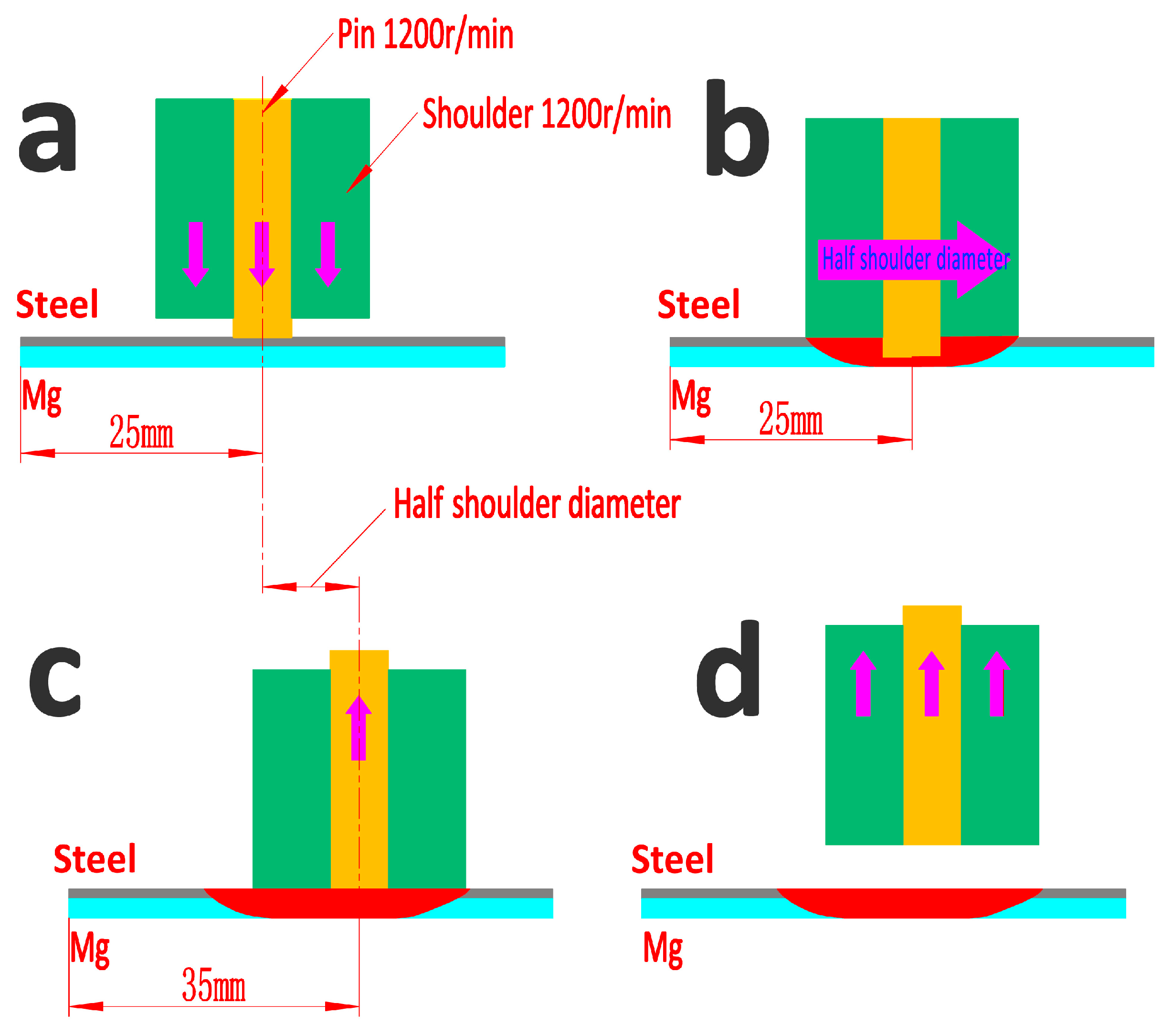
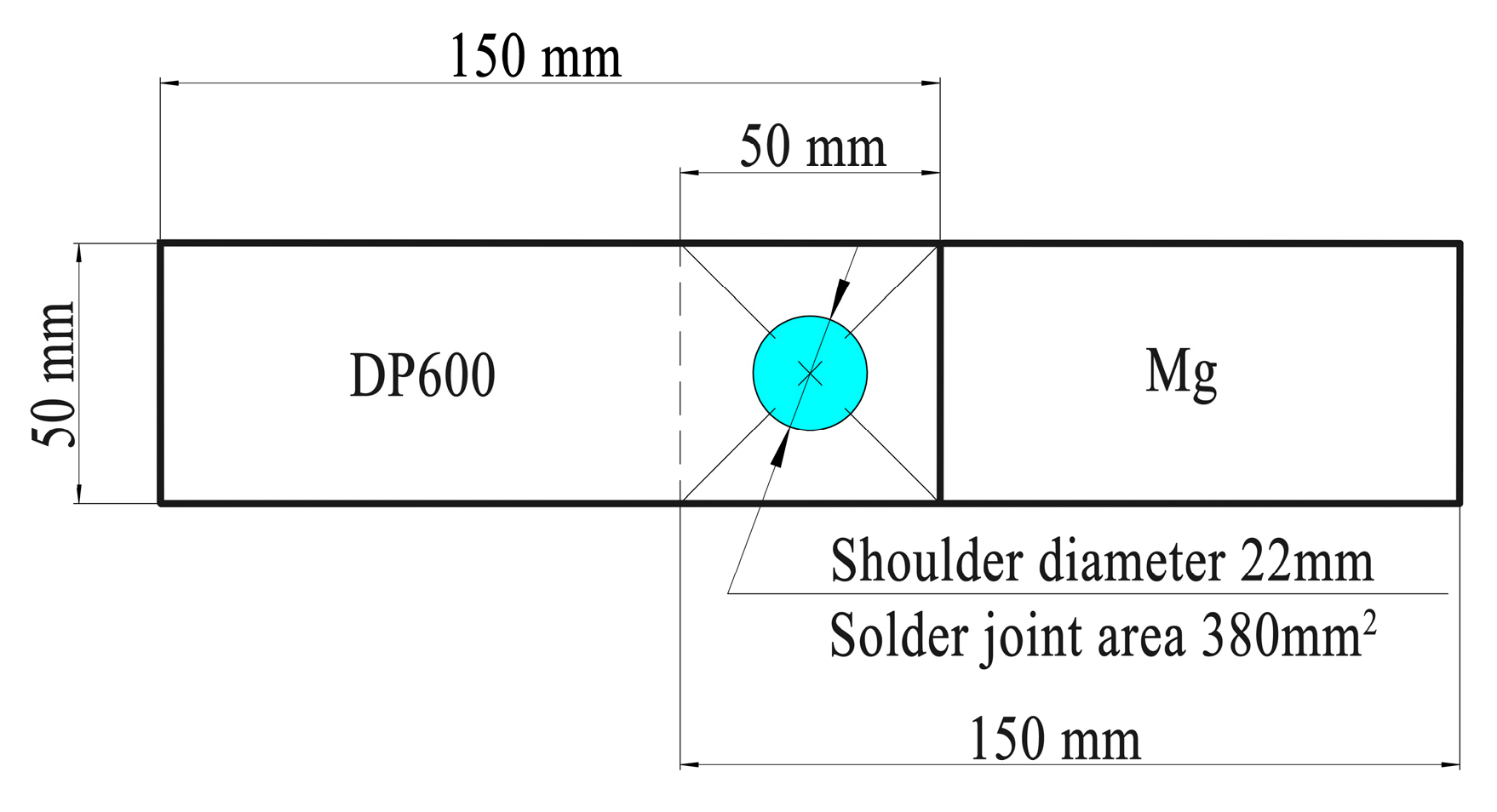
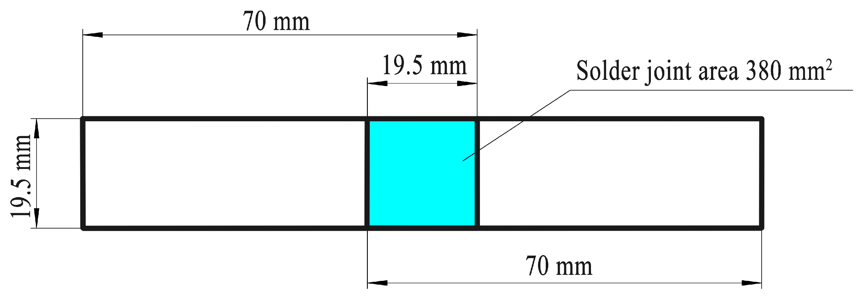
2.2. Methods
3. Results
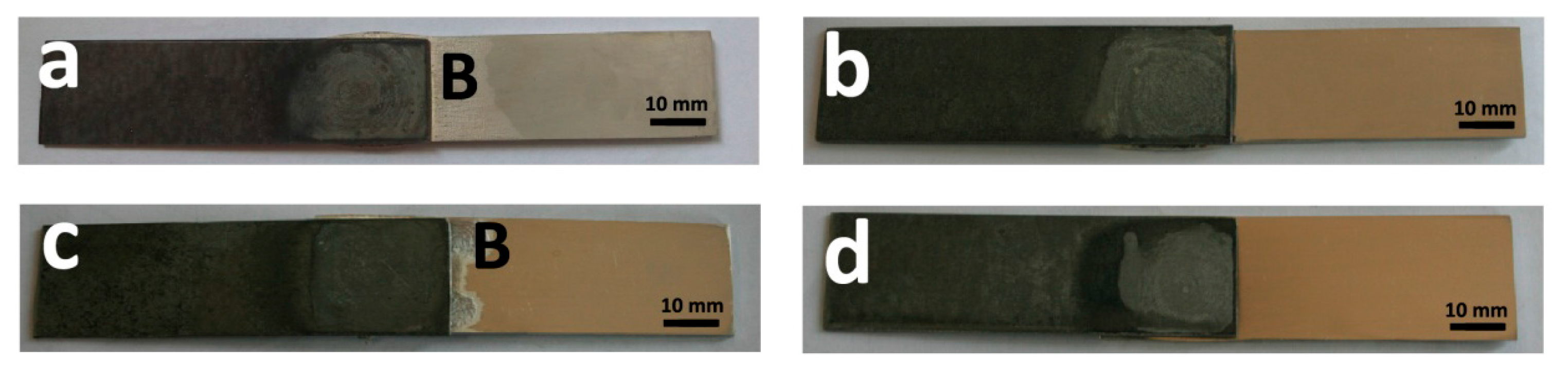
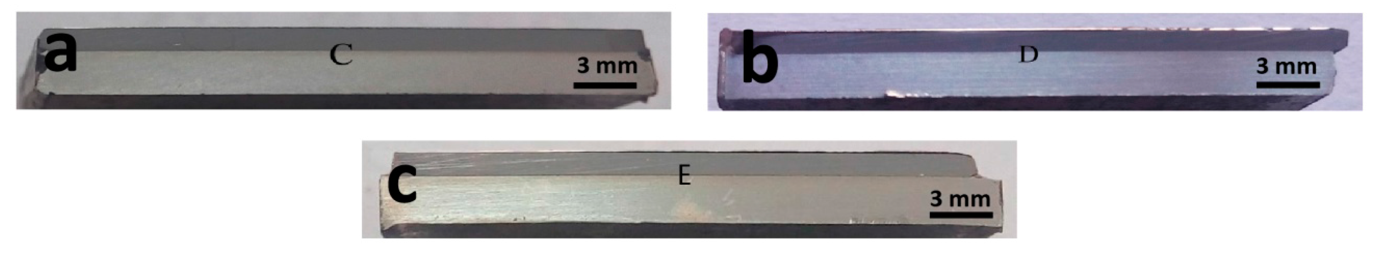
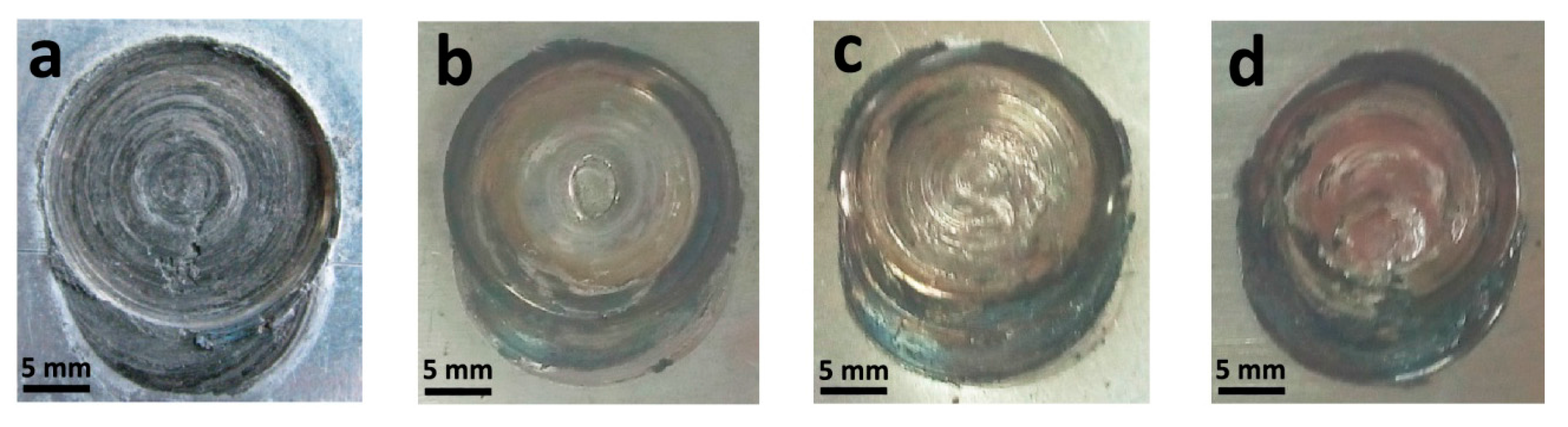
3.1. Joint Formation
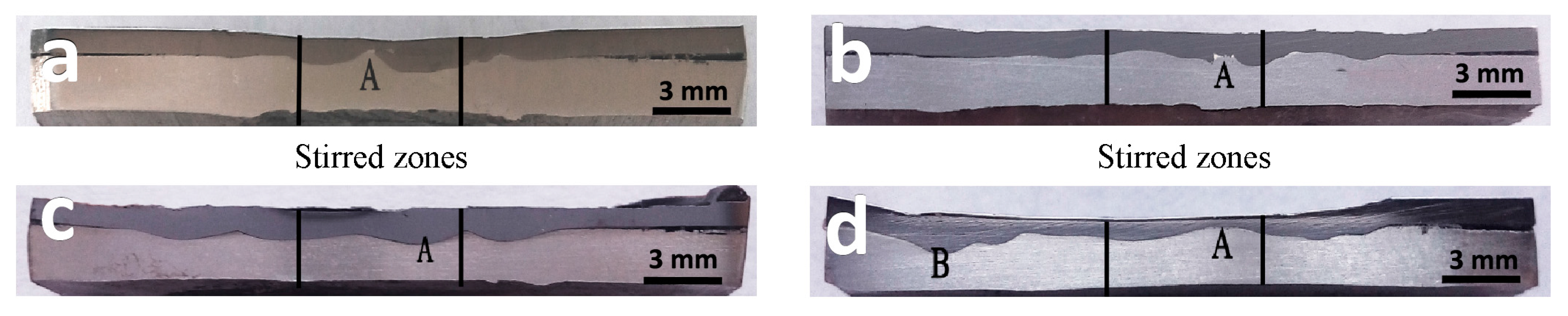
3.2. Macro-Organization Characteristics
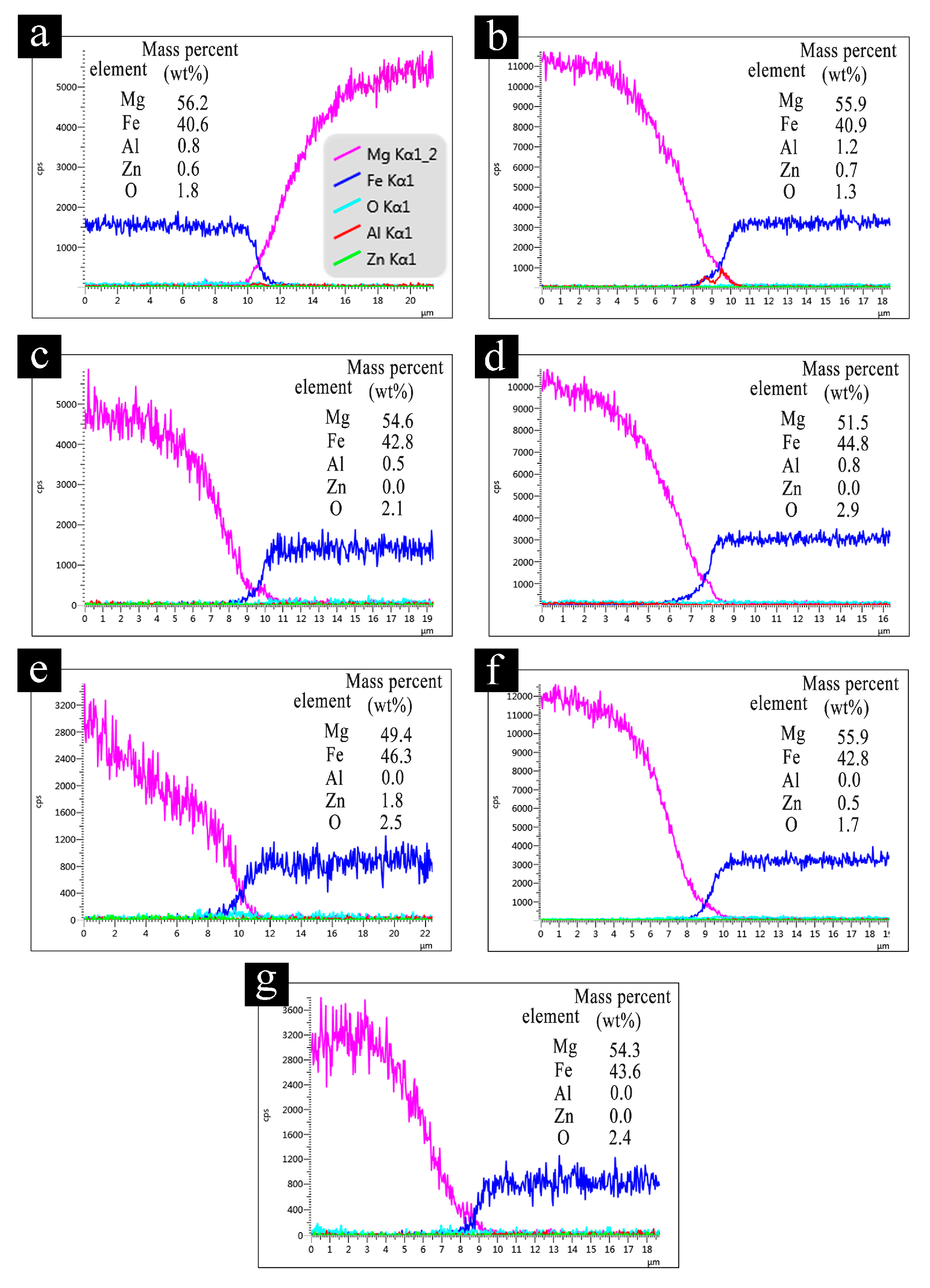
3.3. Degree of Elements Diffusion Analysis of the Joint
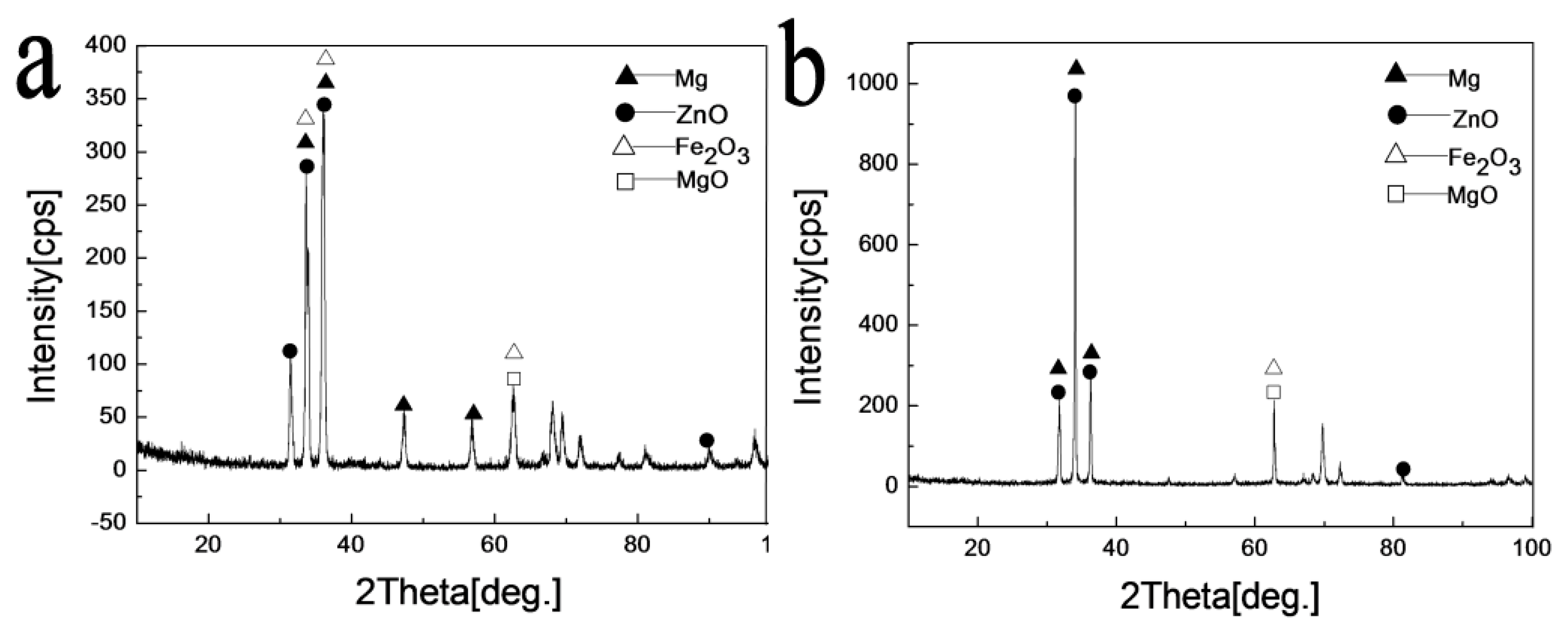
3.4. Phase Analysis of Joints
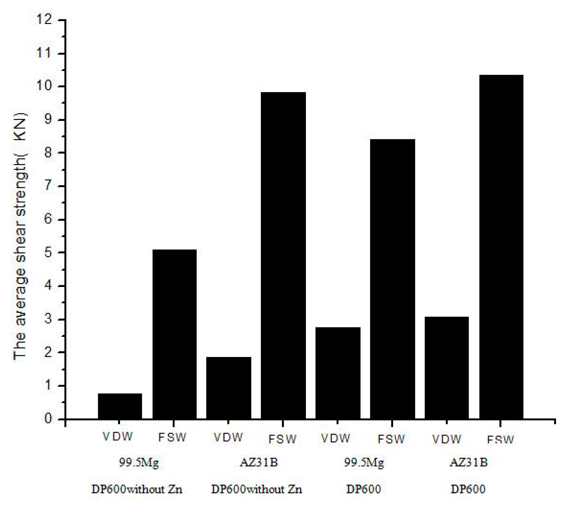
3.5. Mechanical Properties Comparison and Analysis
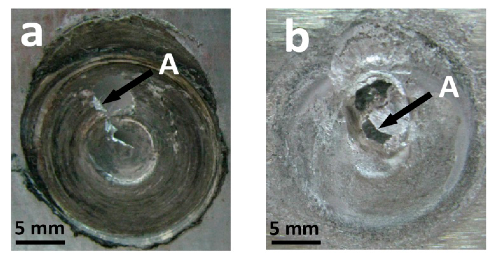
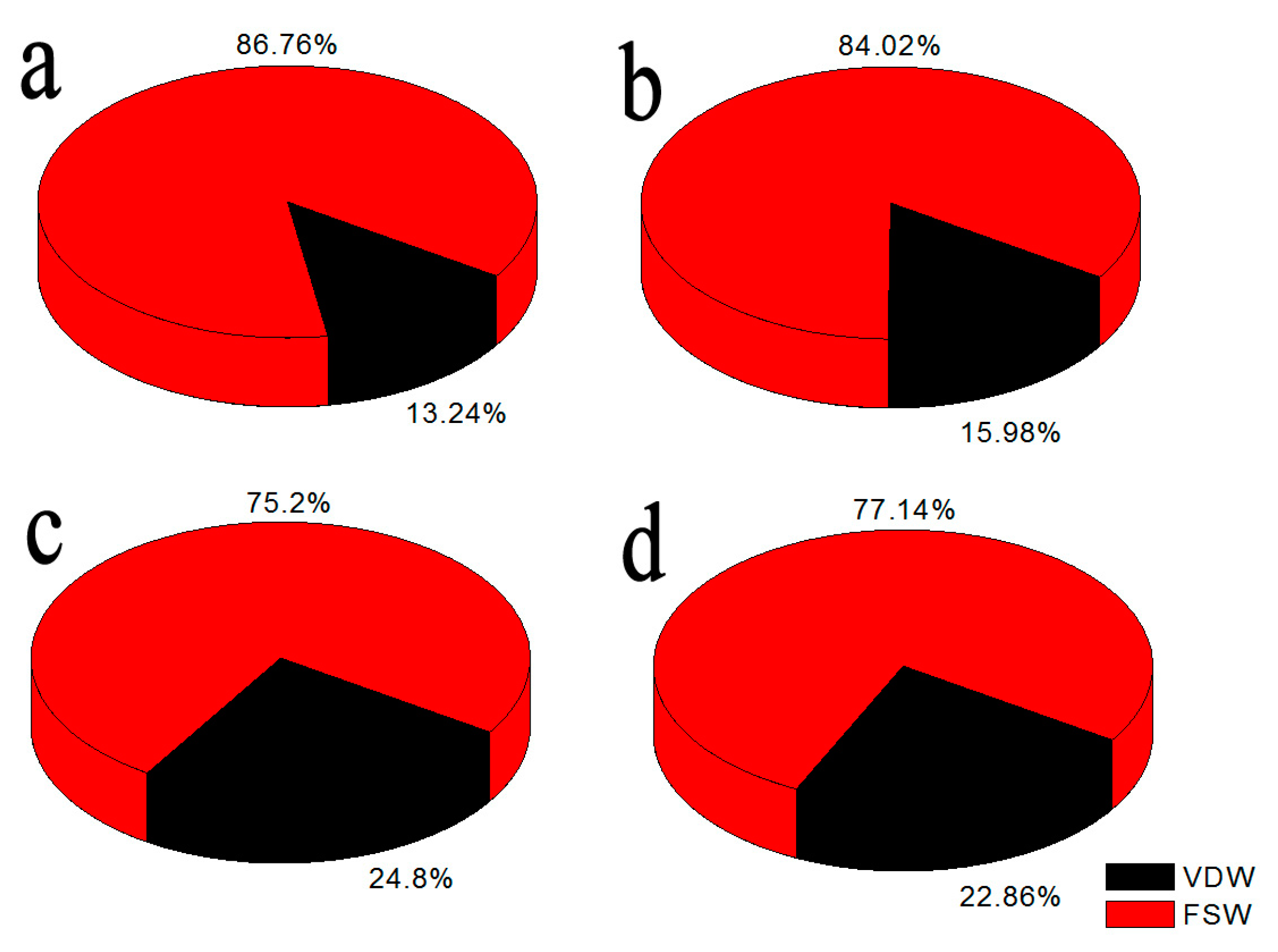
3.6. Analysis of the Effect of Mechanical Connection
4. Conclusions
Acknowledgments
Author Contributions
Conflicts of Interest
References
- Zeng, R.; Wei, K.E.; Yongbo, X.U.; Han, E.; Zhu, Z. Recent development and application of magnesium alloys. Acta Metall. Sin. 2001, 37, 672–685. [Google Scholar]
- Sato, Y.S.; Park, S.H.C.; Michiuchi, M.; Kokawa, H. Constitutional liquation during dissimilar friction stir welding of Al and Mg alloys. Scr. Mater. 2004, 50, 1233–1236. [Google Scholar] [CrossRef]
- Somasekharan, A.C.; Murr, L.E. Microstructures in friction-stir welded dissimilar magnesium alloys and magnesium alloys to 6061–T6 aluminum alloy. Mater. Charact. 2004, 52, 49–64. [Google Scholar] [CrossRef]
- Marya, M.; Edwardz, G.R. Chloride contributions in flusassisted GTA welding of magnesium alloys. Weld. J. 2002, 81, 291–298. [Google Scholar]
- Zhang, Z.D.; Liu, L.M.; Wang, L. Microstructure feature analysis of activating TIG welded joint. Trans. China Weld. Inst. 2004, 25, 55–58. [Google Scholar]
- Mayer, A.; Isakovic, J.T.; Zhuang, H.S. Friction stir spot welding. Weld. Join. 2009, 9, 6–10. [Google Scholar]
- Liu, H.J.; Liu, C.; Shen, J.J.; Liu, Y.Z. Progress in friction stir welding of aluminum to copper. Weld. Join. 2009, 9, 11–15. [Google Scholar]
- Dong, T.; Wang, L.; Lu, C.J.; Wang, M. Study progress of friction stir spot welding at home and abroad. Mod. Weld. Technol. 2012, 2, 1–4. [Google Scholar]
- Fujimoto, M.; Inuzuka, M.; Koga, S. Development of friction spot joining. Weld. World 2005, 49, 18–21. [Google Scholar] [CrossRef]
- Casalinoa, G.; Guglielmia, P.; Lorussoa, V.D.; Mortellob, M.; Peyrec, P.; Sorgenteda, D. Laser offset welding of AZ31B magnesium alloy to 316 stainless steel. J. Mater. Process. Technol. 2017, 242, 49–59. [Google Scholar] [CrossRef]
- Rossini, M.; Spena, P.R.; Cortese, L.; Matteis, P.; Firrao, D. Investigation on dissimilar laser welding of advanced high strength steel sheets for the automotive industry. Mater. Sci. Eng. A 2015, 628, 288–296. [Google Scholar] [CrossRef]
- Thomas, W.; Nicholas, E.D.; Staines, D.; Tubby, P.J.; Gittos, M.F. FSW process variants and mechanical properties. Weld. World 2005, 49, 4–11. [Google Scholar] [CrossRef]
- Lee, C.Y.; Lee, W.B.; Kim, J.W.; Choi, D.H.; Yeon, Y.M.; Jung, S.B. Lap joint properties of FSWed dissimilar formed 5052 Al and 6061 Al alloys with different thickness. J. Mater. Sci. 2008, 43, 3296–3304. [Google Scholar] [CrossRef]
- Nasiri, A.M.; Weckman, D.C.; Zhou, Y. Interfacial Microstructure of Diode Laser Brazed AZ31B Mg to Steel Using a Nickel Interlayer. Weld. J. 2013, 92, 1–10. [Google Scholar]
- Liu, L.; Xiao, L.; Feng, J.C.; Tian, Y.H.; Zhou, S.Q.; Zhou, Y. The Mechanisms of Resistance Spot Welding of Magnesium to Steel. Metall. Mater. Trans. A 2010, 41, 2651–2661. [Google Scholar] [CrossRef]
- Mohammadi, J.; Behnamian, Y.; Mostafaei, A.; Izadi, H.; Saeid, T.; Kokabi, A.H.; Gerlich, A.P. Friction stir welding joint of dissimilar materials between AZ31B magnesium and 6061 aluminum alloys: Microstructure studies and mechanical characterizations. Mater. Charact. 2015, 101, 189–207. [Google Scholar] [CrossRef]
- Xu, R.Z.; Ni, D.R.; Yang, Q.; Liu, C.Z.; Ma, Z.Y. Pinless friction stir spot welding of Mg–3Al–1Zn alloy with Zn interlayer. J. Mater. Sci. Technol. 2016, 32, 76–88. [Google Scholar] [CrossRef]
- Chen, Y.C.; Nakata, K. Effect of surface states of steel on microstructure and mechanical properties of lap joints of magnesium alloy and steel by friction stir welding. Sci. Technol. Weld. Join. 2013, 15, 293–298. [Google Scholar] [CrossRef]
- Chen, Y.C.; Nakata, K. Effect of tool geometry on microstructure and mechanical properties of friction stir lap welded magnesium alloy and steel. Mater. Des. 2009, 30, 3913–3919. [Google Scholar] [CrossRef]
- Wang, X.; Zhang, Y.; Zhang, Z.; Sun, X. Welding analyses of friction stir spot welding without keyhole between aluminum alloy and zinc-coated steel. Trans. China Weld. Inst. 2015, 36, 1–4. [Google Scholar]
- Wang, X.J.; Li, W.H.; Zhao, G. Process analysis on friction stir spot welding without keyhole between magnesium and steel dissimilar alloys. Trans. China Weld. Inst. 2014, 35, 23–26. [Google Scholar]
- Paradiso, V.; Astarita, A.; Carrino, L.; Durante, M.; Franchitti, S.; Scherillo, F.; Squillace, A.; Velotti, C. Numerical optimization of selective superplastic forming of friction stir processed AZ31 Mg alloy. Key Eng. Mater. 2013, 554–557, 2212–2220. [Google Scholar] [CrossRef]
- Carrino, L.; Squillace, A.; Paradiso, V.; Ciliberto, S.; Montuori, M. Superplastic forming of friction stir processed magnesium alloys for aeronautical applications: A modeling approach. Mater. Sci. Forum 2013, 735, 180–191. [Google Scholar] [CrossRef]
- Shen, Z.; Chen, Y.; Haghshenas, M.; Gerlich, A.P. Role of welding parameters on interfacial bonding in dissimilar steel/aluminum friction stir welds. Eng. Sci. Technol. Int. J. 2015, 18, 270–277. [Google Scholar] [CrossRef]
- Chiteka, K. Friction Stir Welding of steels: A Review Paper. J. Mech. Civ. Eng. 2013, 9, 16–20. [Google Scholar]
- Wang, X.; Zhao, G.; Zhang, Z.; Wang, P. Process research on friction stir spot welding without key hole between magnesium and steel dissimilar alloys. Hot Work. Technol. 2014, 41, 153–155. [Google Scholar]
- Zhang, Z.K.; Wang, X.J.; Wang, P.C.; Zhao, G. Friction stir keyholeless spot welding of AZ31 Mg alloy-mild steel. Trans. Nonferr. Met. Soc. China 2014, 24, 1709–1716. [Google Scholar] [CrossRef]
- Shiri, S.G.; Sarani, A.; Hosseini, S.R.E.; Roudini, G. Diffusion in FSW joints by inserting the metallic foils. J. Mater. Sci. Technol. 2013, 29, 1091–1095. [Google Scholar] [CrossRef]
- Shi, H.; Chen, K.; Liang, Z.; Dong, F.; Yu, T.; Dong, X.; Zhang, L.; Shan, A. Intermetallic compounds in the banded structure and their effect on mechanical properties of Al/Mg dissimilar friction stir welding joints. J. Mater. Sci. Technol. 2017, 33, 359–366. [Google Scholar] [CrossRef]
- Ji, S.D.; Jin, Y.Y.; Yue, Y.M.; Gao, S.S.; Huang, Y.X.; Wang, L. Effect of temperature on material transfer behavior at different stages of friction stir welded 7075–T6 aluminum alloy. J. Mater. Sci. Technol. 2013, 29, 955–960. [Google Scholar] [CrossRef]


| Alloys | Al | Zn | Mn | Si | Fe | Cu | Ni | Mg |
|---|---|---|---|---|---|---|---|---|
| AZ31B | 2.5–3.5 | 0.6–1.4 | 0.2–1.0 | 0.80 | 0.003 | 0.01 | 0.001 | Balance |
| Mg99.50 | - | - | - | - | - | - | - | ≥99.50 |
| C | Si | Mn | P | S | Al | N | Fe |
|---|---|---|---|---|---|---|---|
| 0.079 | 1.00 | 1.52 | 0.015 | 0.005 | 0.023 | 0.0037 | Balance |
| Joint Type | Joint 1 | Joint 2 | Joint 3 | Average |
|---|---|---|---|---|
| AZ31B–DP600 FSKSW | 9.98 | 11.75 | 10.36 | 10.36 |
| AZ31B–DP600 VDW | 3.35 | 3.02 | 2.86 | 3.07 |
| AZ31B–non-zinc-coated DP600 FSKSW | 11 | 9.4 | 9.1 | 9.83 |
| AZ31B–non-zinc-coated DP600 VDW | 1.575 | 1.8 | 2.225 | 1.87 |
| Mg99.50–DP600 FSKSW | 7.2 | 10.2 | 7.8 | 8.4 |
| Mg99.50–DP600 VDW | 2.2 | 2.3 | 3.8 | 2.77 |
| Mg99.50–non-zinc-coated DP600 FSKSW | 3.14 | 6.9 | 5.3 | 5.11 |
| Mg99.50–non-zinc-coated DP600 VDW | 0.55 | 0.8 | 0.5 | 0.61 |
© 2017 by the authors. Licensee MDPI, Basel, Switzerland. This article is an open access article distributed under the terms and conditions of the Creative Commons Attribution (CC BY) license (http://creativecommons.org/licenses/by/4.0/).
Share and Cite
Liu, X.; Wang, X.; Wang, B.; Zhang, L.; Yang, C.; Chai, T. The Role of Mechanical Connection during Friction Stir Keyholeless Spot Welding Joints of Dissimilar Materials. Metals 2017, 7, 217. https://doi.org/10.3390/met7060217
Liu X, Wang X, Wang B, Zhang L, Yang C, Chai T. The Role of Mechanical Connection during Friction Stir Keyholeless Spot Welding Joints of Dissimilar Materials. Metals. 2017; 7(6):217. https://doi.org/10.3390/met7060217
Chicago/Turabian StyleLiu, Xiao, Xijing Wang, Boshi Wang, Liangliang Zhang, Chao Yang, and Tingxi Chai. 2017. "The Role of Mechanical Connection during Friction Stir Keyholeless Spot Welding Joints of Dissimilar Materials" Metals 7, no. 6: 217. https://doi.org/10.3390/met7060217
APA StyleLiu, X., Wang, X., Wang, B., Zhang, L., Yang, C., & Chai, T. (2017). The Role of Mechanical Connection during Friction Stir Keyholeless Spot Welding Joints of Dissimilar Materials. Metals, 7(6), 217. https://doi.org/10.3390/met7060217