Statistical Approach to Optimize the Process Parameters of HAZ of Tool Steel EN X32CrMoV12-28 after Die-Sinking EDM with SF-Cu Electrode


Abstract
:1. Introduction
2. Materials and Methods
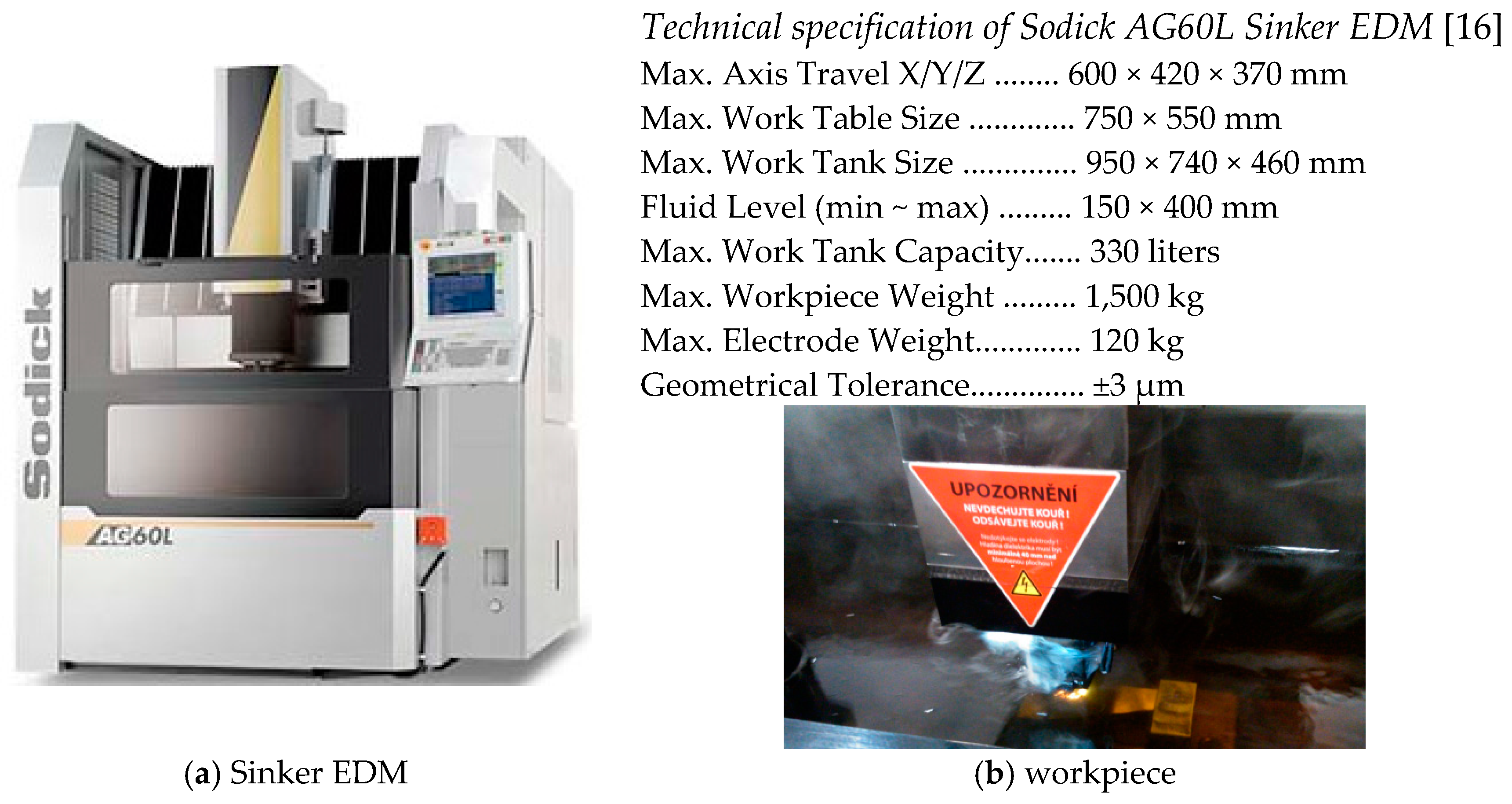
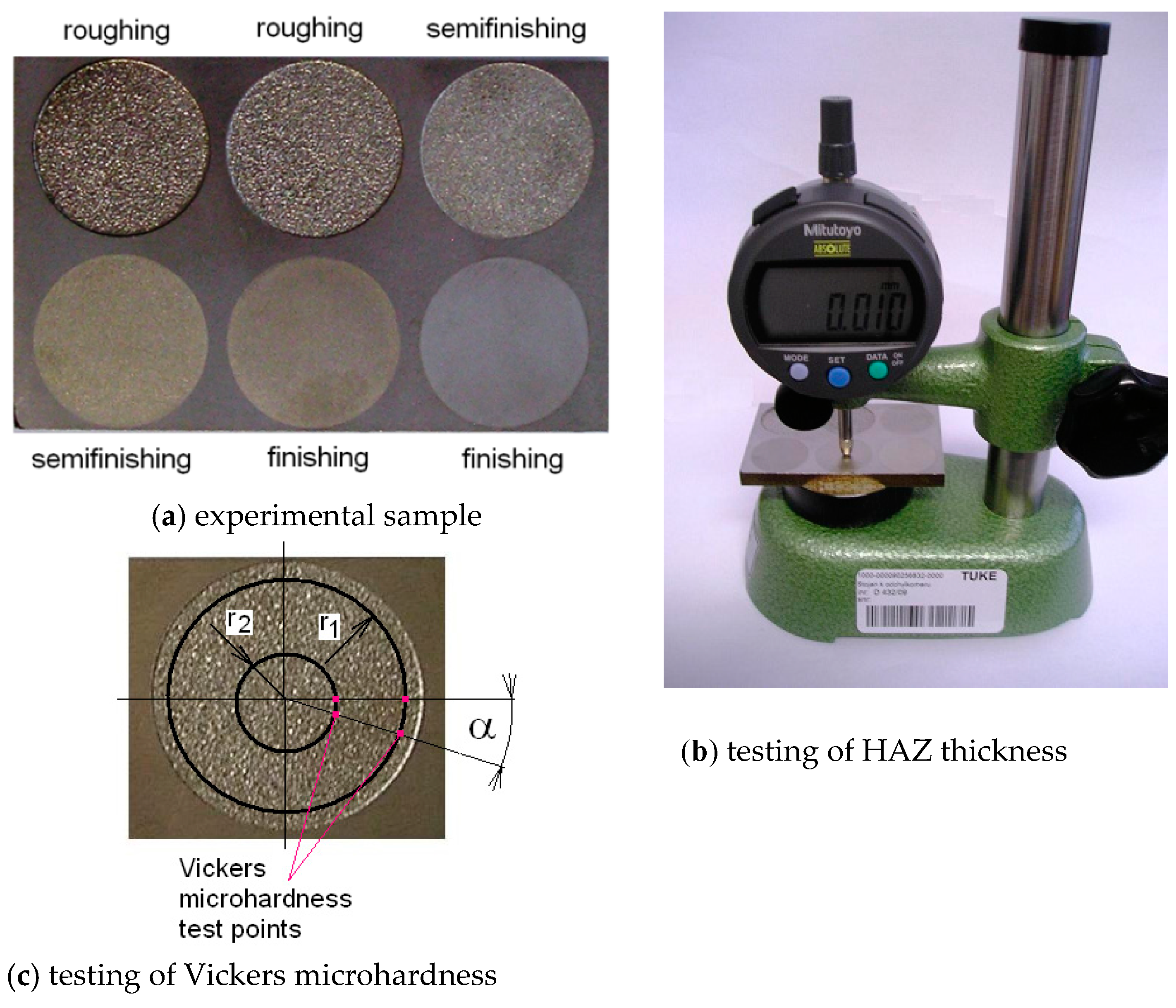
2.1. Equipment and Tools Used in Experiments
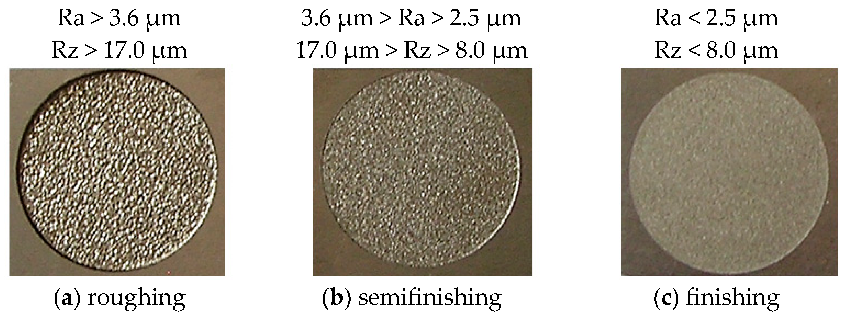
2.2. Production of Experimental Samples
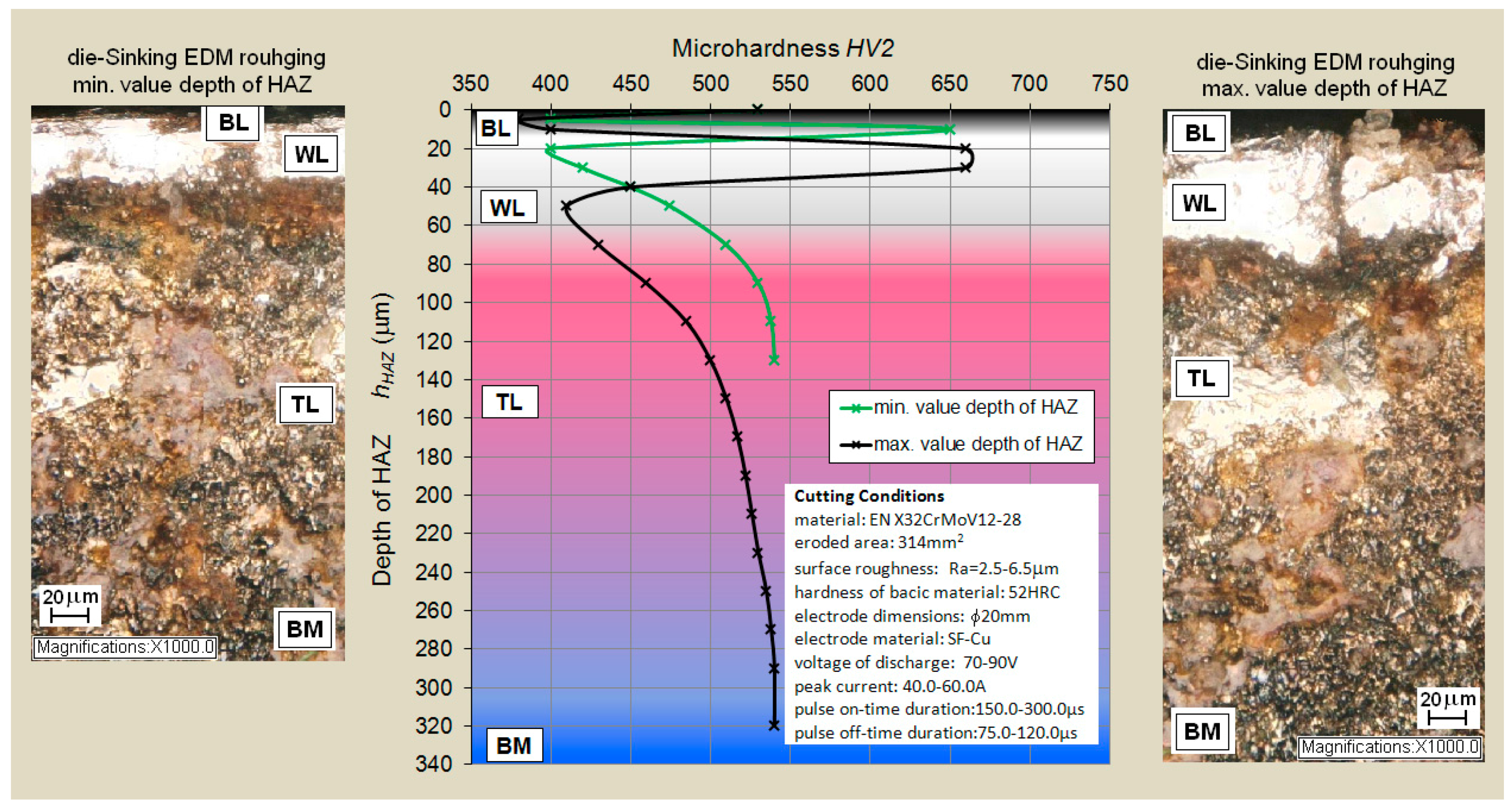
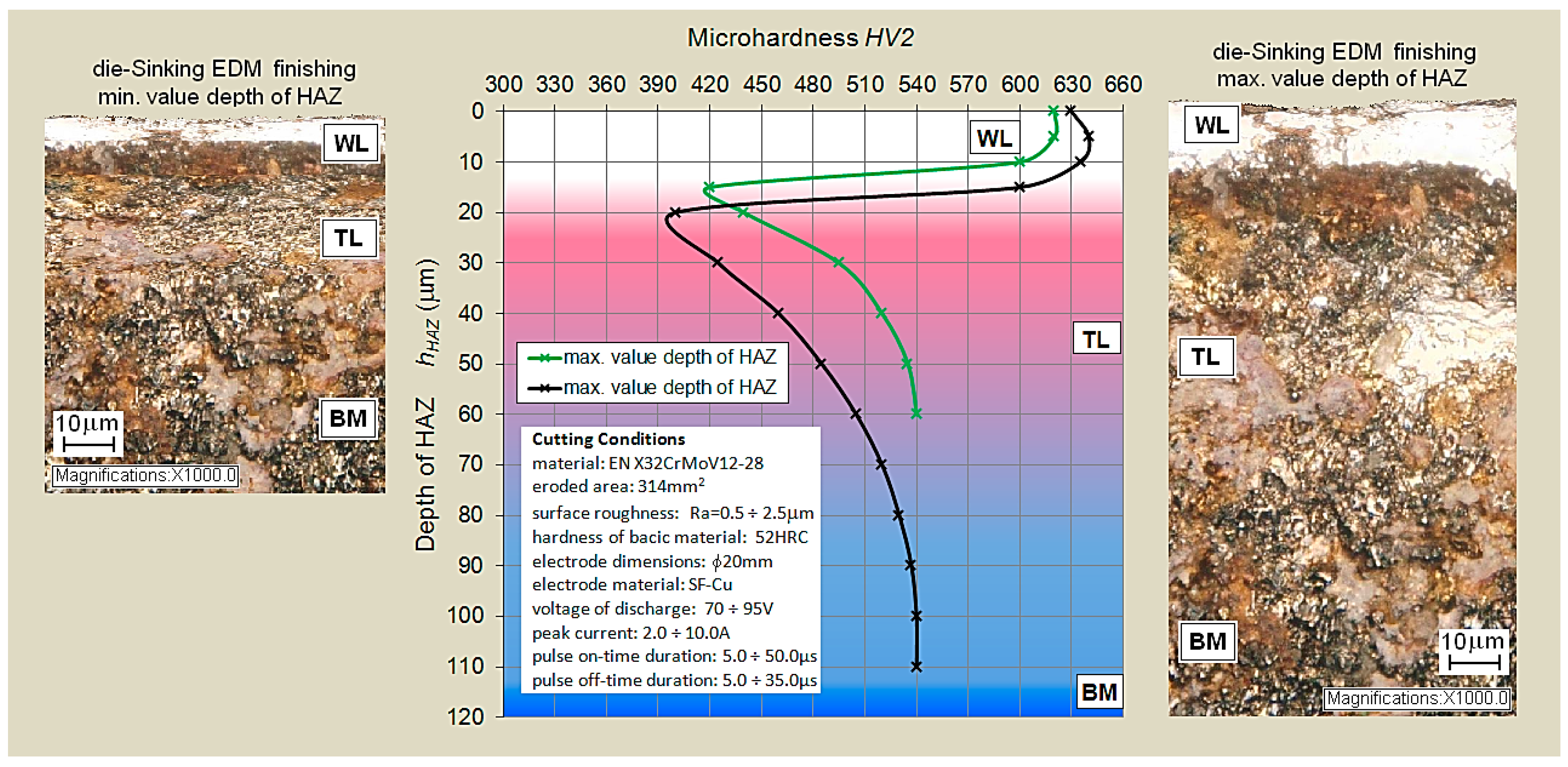
2.3. Measurements of Microhardness and Total HAZ Depth
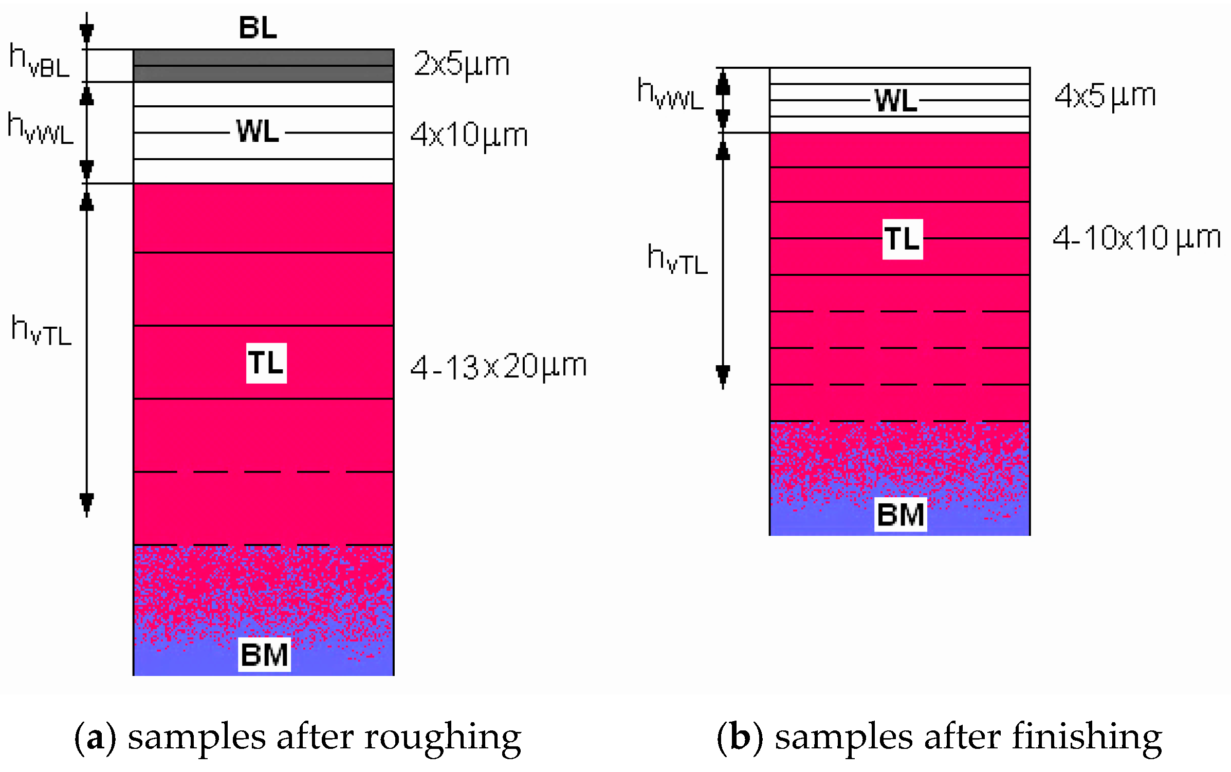
- hHAZt—assumed (theoretical) total HAZ thickness,
- hvBL—facet thickness in BL (for roughing approx. 5 µm),
- hvWL—facet thickness in WL (for roughing approx. 10 µm; for finishing approx. 5 µm),
- hvTL—facet thickness in TL (for roughing approx. 20 µm; for finishing approx. 10 µm),
- nvBL—number of facets in BL (for roughing 2×),
- nvWL—number of facets in WL (for roughing and finishing 4×),
- nvTL—number of facets in TL (for roughing and finishing as needed).
3. Results and Discussions
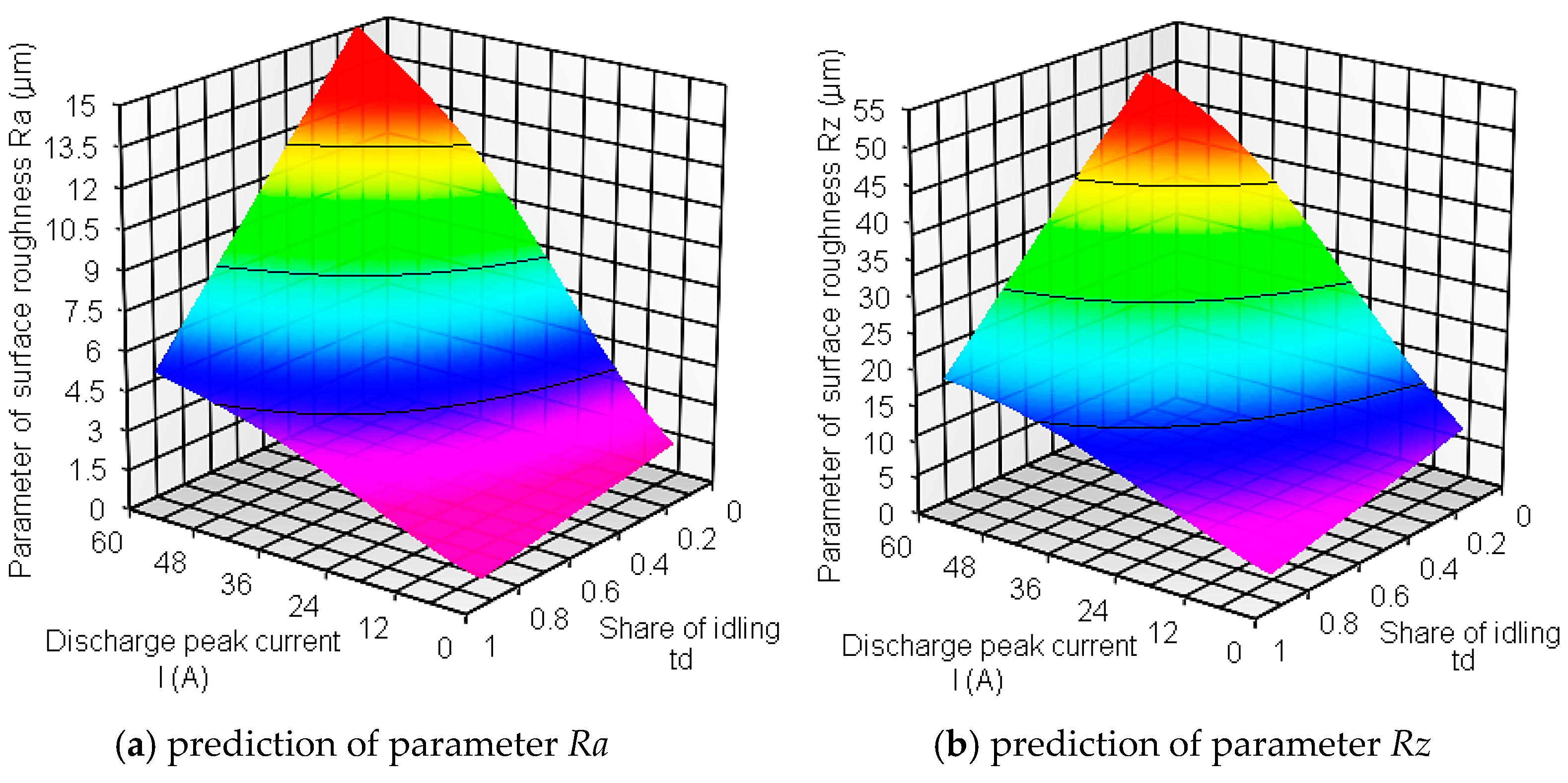
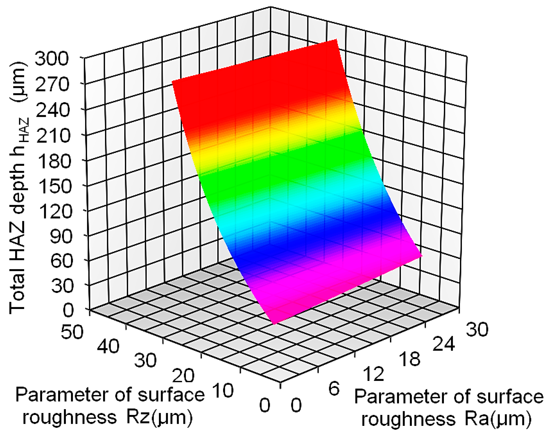
3.1. Prediction of HAZ Size of Tool Steel EN X32CrMoV12-28 after Die-Sinking EDM with SF-Cu Electrode
- -
- peak current I ranging from 2–60 A;
- -
- pulse on-time duration ton ranging from 5–300 µs;
- -
- pulse off-time duration toff ranging from 5–120 µs.
- I—peak current [A],
- td—ratio of idling, defined by formula (9).
- hHAZ—is total thickness hHAZ [µm],
- Ra, Rz—are machined surface roughness parameters [µm].
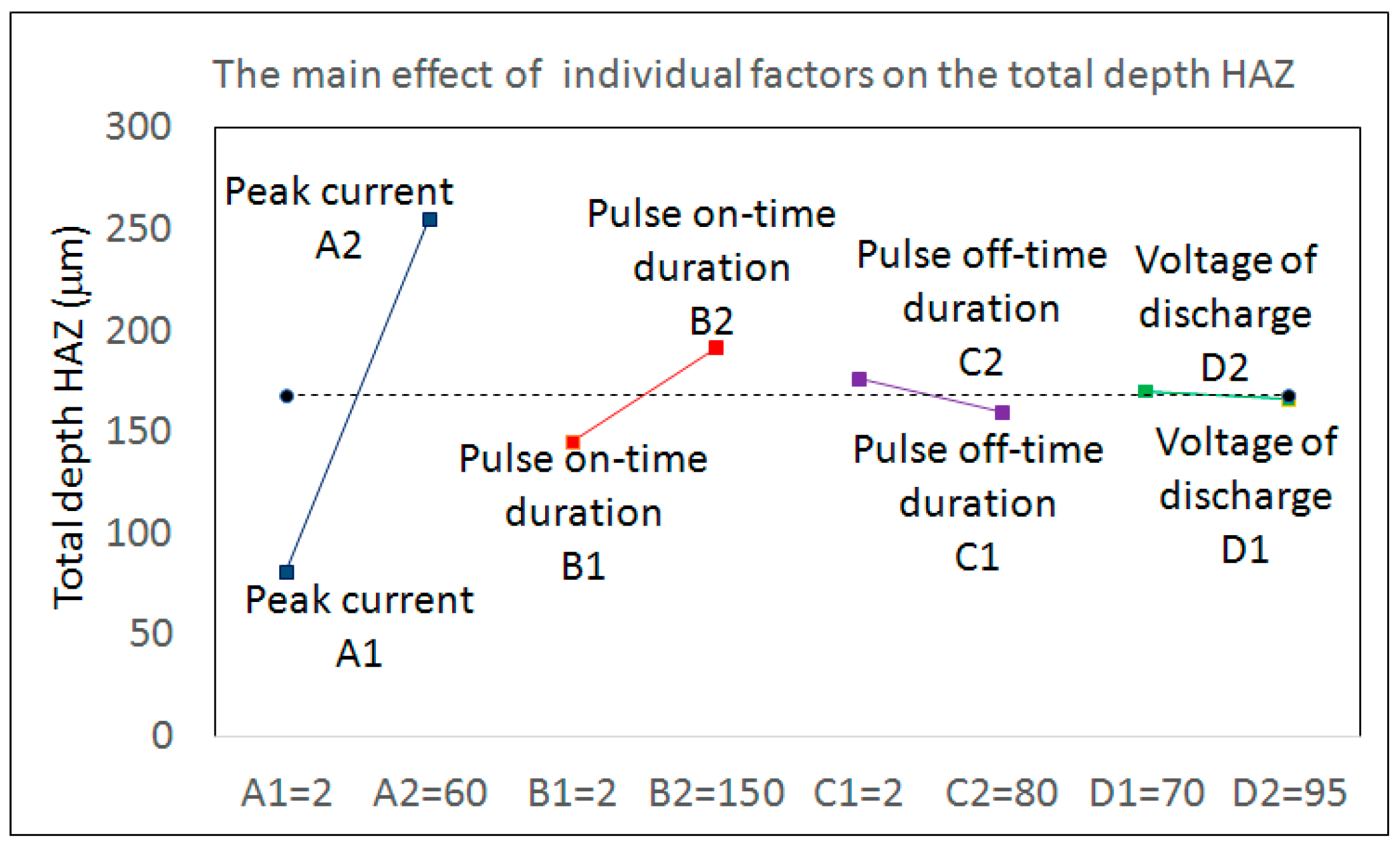
3.2. Practical Recommendation for Optimization of Total HAZ Thickness
4. Conclusions
- ▪
- based on the results of experimental research of sub-surface layers of mildly-alloyed chrome-molybdenum-vanadium tool steel EN X32CrMoV12-28 (W.-Nr. 1.2365) after die-sinking EDM with SF-Cu electrode, the main technological parameters (I, ton and toff) that significantly affect the quality of machined surface in terms of microstructural changes were selected;
- ▪
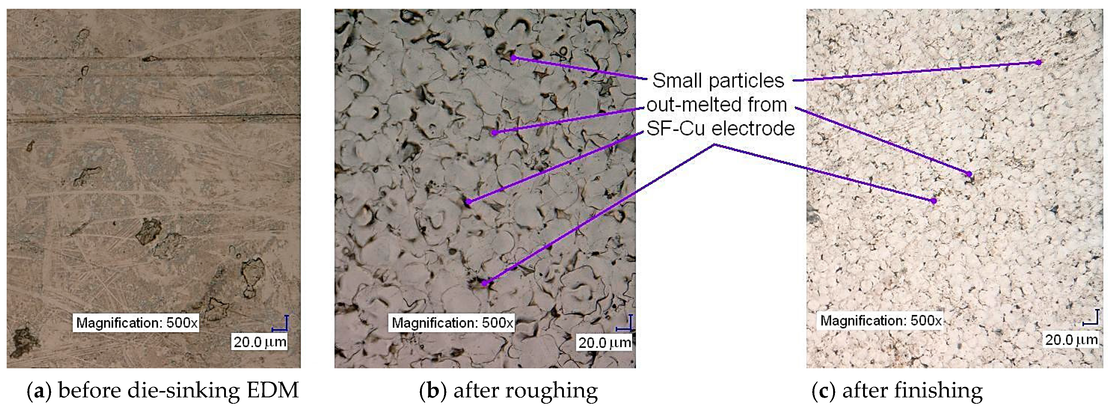
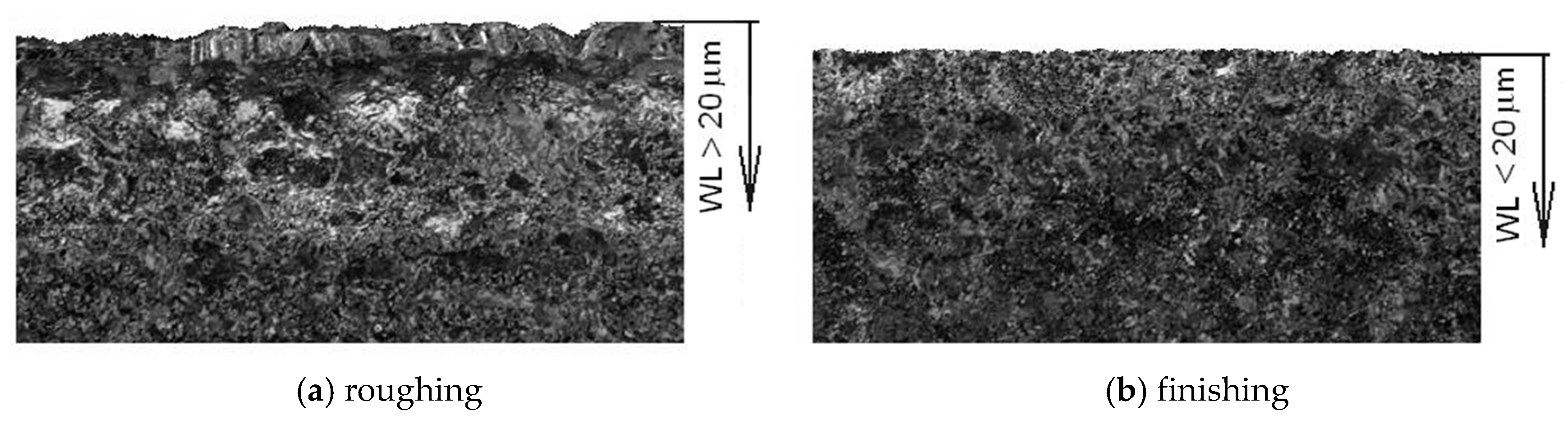
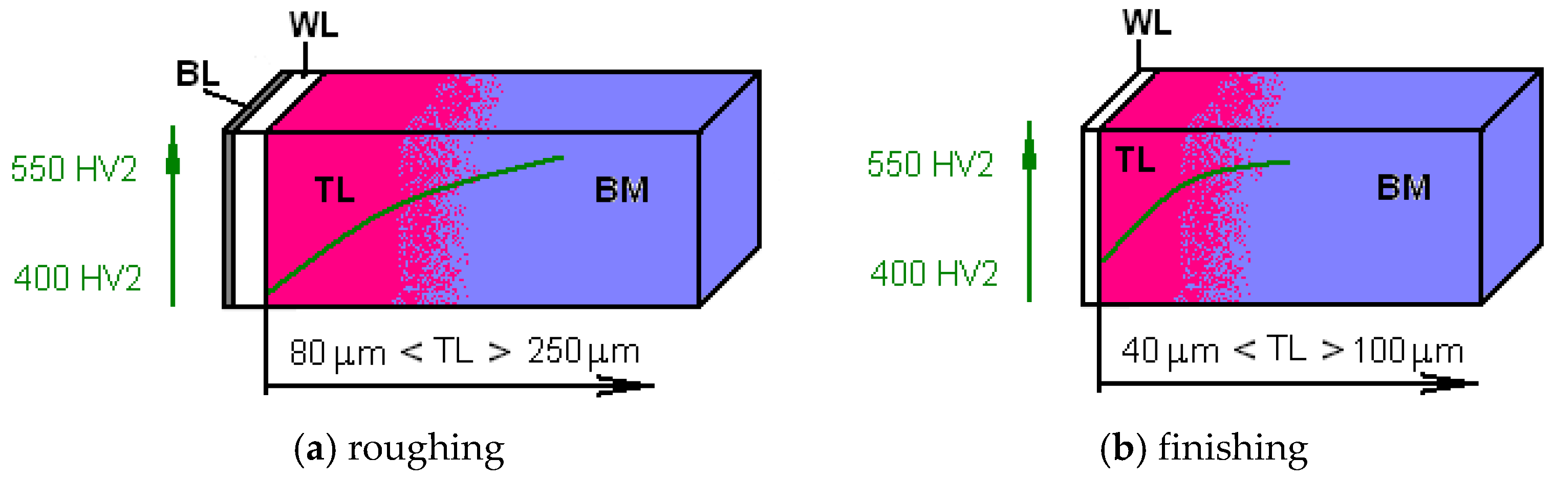
- in the heat affected zone (HAZ) three layers (BL, WL and TL) were identified as having a specific microstructure, mechanical, physical, and chemical properties;
- ▪
- for each layer of HAZ of tool steel EN X32CrMoV12-28 the range of thicknesses, and the microhardness change depending on the setting of important technological parameters in die-sinking EDM with a SF-Cu electrode were determined;
- ▪
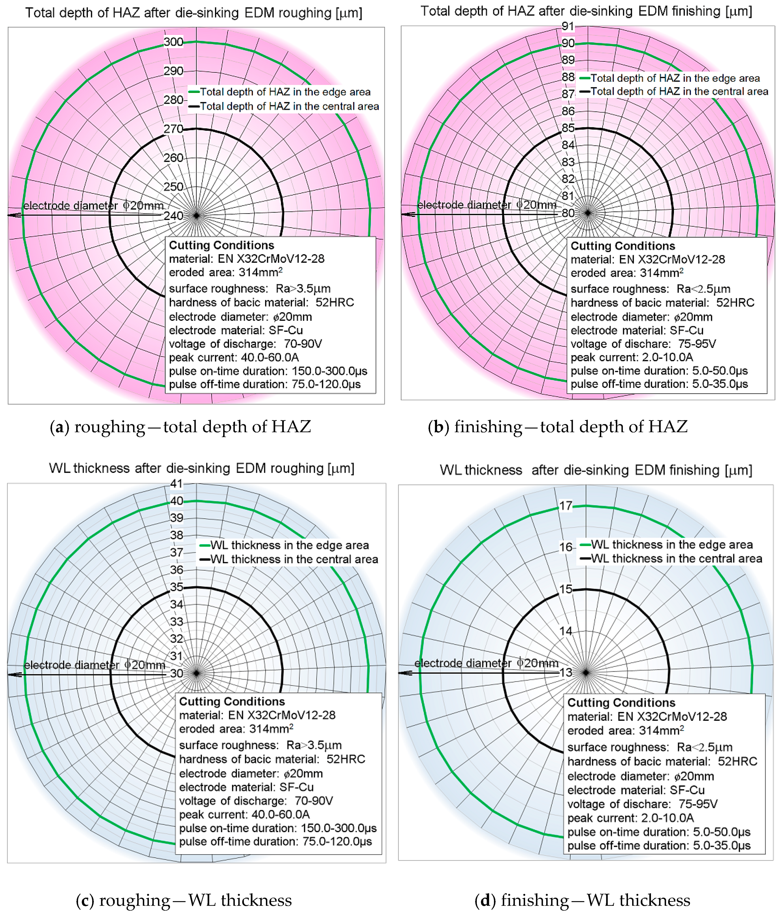
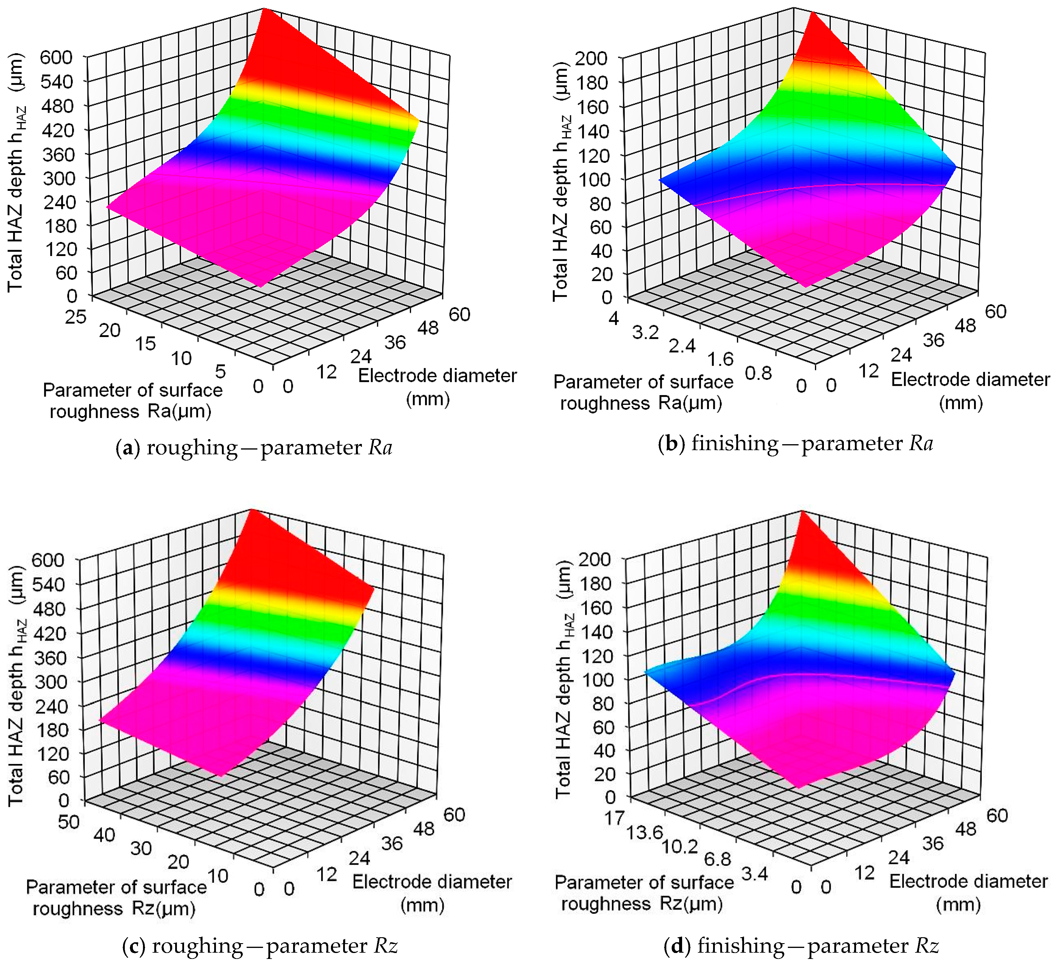
- total thickness hHAZ was determined for the roughing (120 to 280 µm), and finishing operation (60 to 100 µm) with a SF-Cu electrode of 20 mm diameter;
- ▪
- based on mathematical modeling the total HAZ thickness was predicted of the tool steel EN X32CrMoV12-28 at die-sinking EDM for SF-Cu electrodes with diameters ranging from 5 to 60 mm;
- ▪
- there is the possibility of application of established mathematical models for the optimal selection of values of significant technological parameters in die-sinking EDM of tool steel EN X32CrMoV12-28 with SF-Cu electrode of diameter in the range from 5 to 60 mm, based on the required maximum thickness hHAZ;
- ▪
- on the basis of the defined causes, the measures for elimination of the increase of the total thickness hHAZ were proposed;
- ▪
- on the basis of the defined causes of HAZ inhomogeneity deviations in the middle of the eroded area compared to the area boundaries, reaching a level of 10%, the measures for elimination of the deviations were proposed;
- ▪
- experimental research of HAZ of the machined surface of tool steel EN X32CrMoV12-28 after die-sinking EDM with a SF-Cu electrode was oriented on the practical application of the results in theory, as well as in technical practice;
- ▪
- the achieved results of the experimental measurements represent partial results of an extensive set of experimental measurements focused on the creation of a complex database containing data that describe the influence of process parameters on surface roughness and total HAZ depth at die-sinking EDM of tool steels [44];
- ▪
- the achieved results and proposed solutions concerning prediction make it possible to meet a much closer specification of the requirements, imposed on quality of the machined surface at die-sinking EDM with a SF-Cu electrode.
Acknowledgments
Author Contributions
Conflicts of Interest
References
- Kompella, S.; Moylan, S.; Chandrasekar, S. Mechanical properties of thin surface layers affected by material removal processes. Surf. Coat. Technol. 2001, 146, 384–390. [Google Scholar] [CrossRef]
- Ťavodová, M. Research state heat affected zone of the material after wire EDM. Acta Fac. Tech. 2014, 19, 145–152. [Google Scholar]
- Choudhary, R.; Kumar, H.; Gark, R.K. Analysis and evaluation of heat affected zones in electric discharge machining of EN-31 die steel. Indian J. Eng. Mater. Sci. 2010, 2, 91–98. [Google Scholar]
- Shrestha, T.; Alsagabi, S.F.; Charit, I.; Potirniche, G.P.; Glazoff, M.V. Effect of heat treatment on microstructure and hardness of grade 91 steel. Metals 2015, 5, 131–149. [Google Scholar] [CrossRef]
- Čada, R.; Zlámalík, J. Materials comparison of cutting tools functional parts for cutting of electrical engineering sheets. Trans. VŠB–Ostrava Mech. Ser. 2012, 33–41. Available online: http://transactions.fs.vsb.cz/2012–1/1892.pdf (accessed on 18 April 2016). [Google Scholar]
- Švecová, V.; Madaj, M. Surface characteristics evaluation of the VANADIS 23 high speed steel punch after Wire Electrical Discharge Machining. Stroj. Technol. 2012, 40–41. Available online: http://casopis.strojirenskatechnologie.cz/templates/obalky_casopis/XVII_1,2_2012.pdf (accessed on 24 January 2017). [Google Scholar]
- Abu Zeid, O.A. On the effect of electro-discharge machining parameters on the fatigue life of AISI D6 tool steel. J. Mater. Process. Technol. 1997, 68, 27–32. [Google Scholar] [CrossRef]
- Marafona, J. Black layer characterisation and electrode wear ratio in electrical discharge machining (EDM). J. Mater. Process. Technol. 2007, 184, 27–31. [Google Scholar] [CrossRef]
- Ekmekci, B. Residual stresses and white layer in electric discharge machining (EDM). Appl. Surf. Sci. 2007, 253, 9234–9240. [Google Scholar] [CrossRef]
- Zang, Y.; Liu, Y.; Ji, R.; Cai, B. Study of the recast layer of a surface machined by sinking electrical discharge machining using water-in-oil emulsion as dielectric. Appl. Surf. Sci. 2011, 257, 5989–5997. [Google Scholar] [CrossRef]
- Dewangan, S.; Gangopadhyay, S.; Biswas, C.K. Study of surface integrity and dimensional accuracy in EDM using Fuzzy TOPSIS and sensitivity analysis. Measurement 2015, 63, 364–376. [Google Scholar] [CrossRef]
- Sidhom, H. Effect of electro discharge machining (EDM) on the AISI316L SS white layer microstructure and corrosion resistance. Int. J. Adv. Manuf. Technol. 2012, 1–4, 141–153. [Google Scholar] [CrossRef]
- Puri, A.B.; Bhattacharyya, B. Modeling and analysis of white layer depth in a wire-cut EDM process through response surface methodology. Int. J. Adv. Manuf. Technol. 2005, 3–4, 301–307. [Google Scholar] [CrossRef]
- STN ISO 4287 Surface Roughness Testing. Available online: http://www.gagesite.com/documents/Training/Mitutoyo%20Surface%20Analysis_April%202%202014%20at%20PQI.pdf (accessed on 17 August 2016).
- STN ISO 6507 Vickers Hardness Testing. Available online: http://infostore.saiglobal.com/store/PreviewDoc.aspx?saleItemID=40729 (accessed on 17 August 2016).
- Sodick Technical Specifications. Available online: http://www.sodick.com/products/sinkeredm/ag60l.htm (accessed on 17 August 2016).
- Material Card of Copper SF-Cu (W.-Nr. 2.0090). Available online: https://www.google.sk/#q=Material+Card+of+Copper+SF-Cu+(W.-Nr.2.0090) (accessed on 18 April 2016).
- Material Card of Steel EN X210Cr12. Available online: http://www.usbcosteels.com/pdffile/OCR12.pdf (accessed on 18 April 2016).
- Krastev, D. Improvement of Corrosion Resistance of Steels by Surface Modification. Available online: http://cdn.intechopen.com/pdfs/34491/InTech-Improvement_of_corrosion_resistance_of_steels_by_surface_modification.pdf (accessed on 24 January 2017).
- Lei, M.K.; Zang, Z.L. Microstructure and Corrosion Resistance of Plasma Source Ion Nitrided Austenitic Stainless Steel. J. Vac. Sci. Technol. 1997, 2, 421–427. [Google Scholar] [CrossRef]
- Bátora, B.; Vasilko, K. Obrobené Povrchy (Machined Surfaces); University of Trenčín: Trenčín, Slovakia, 2000; p. 183. [Google Scholar]
- Banker, K.S.; Parmar, S.P.; Parekh, B.C. Review to Performance Improvement of Die Sinking EDM Using Powder Mixed Dielectric Fluid. Int. J. Res. Modern Eng. Emerg. Technol. 2013, 1, 57–62. [Google Scholar]
- Cusanelli, G.; Hessler-Wyser, A.; Bobard, F.; Demellayer, R.; Perez, R.; Flükiger, R. Microstructure at submicron scale of the white layer produced by EDM technique. J. Mater. Process. Technol. 2004, 1, 289–295. [Google Scholar] [CrossRef]
- Zhang, Y.; Cheng, X.; Zhong, H.; Xu, Z.; Li, L.; Gong, Y.; Miao, X.; Song, C.; Zhai, Q. Comparative Study on the Grain Refinement of Al-Si Alloy Solidified under the Impact of Pulsed Electric Current and Travelling Magnetic Field. Metals 2016, 6. [Google Scholar] [CrossRef]
- Ekmekci, B. White layer composition, heat treatment and crack formation in electric discharge machining process. Metall. Mater. Trans. B: Process Metall. Mater. Processing Sci. 2009, 40B, 70–81. [Google Scholar] [CrossRef]
- Straka, Ľ.; Čorný, I. Heat treating of chrome tool steel before electroerosion cutting with brass electrode. Acta Metall. Slovaca 2009, 15, 180–186. [Google Scholar]
- Mathew, S.; Varma, P.R.D.; Kurian, P.S. Study on the Influence of process parameters on surface roughness and MRR of AISI 420 stainless steel machined by EDM. Int. J. Eng. Trends Technol. 2014, 2, 54–58. [Google Scholar] [CrossRef]
- Straka, Ľ.; Čorný, I.; Piteľ, J. Properties evaluation of thin microhardened surface layer of tool steel after wire EDM. Metals 2016, 6. [Google Scholar] [CrossRef]
- Kim, J.M.; Ha, T.H.; Park, J.S.; Kim, H.G. Effect of laser surface treatment on the corrosion behavior of FeCrAl-coated TZM alloy. Metals 2016, 6. [Google Scholar] [CrossRef]
- Saha, S.K.; Chaudhary, S.K. Experimental investigation and empirical modeling of the dry electrical discharge machining process. Int. J. Mach. Tool. Manuf. 2009, 49, 297–308. [Google Scholar] [CrossRef]
- Das, S.; Klotz, M.; Klocke, F. EDM simulation finite element-based calculation of deformation, microstructure and residual stresses. J. Mater. Process. Technol. 2003, 142, 434–451. [Google Scholar] [CrossRef]
- Kiyak, M.; Cakir, O. Examination of machining parameters on surface roughness in EDM of tool steel. J. Mater. Process. Technol. 2007, 1–3, 41–144. [Google Scholar] [CrossRef]
- Salonitis, K.; Stournaras, A.; Stavropoulos, P.; Chryssolouris, G. Thermal modeling of the material removal rate and surface roughness for die-sinking EDM. Int. J. Adv. Manuf. Technol. 2009, 40, 316–323. [Google Scholar] [CrossRef]
- Ho, K.H.; Newman, S.T. State of the art electrical discharge machining (EDM). Int. J. Mach. Tools Manuf. 2003, 13, 1287–1300. [Google Scholar] [CrossRef]
- Mičietová, A.; Neslušan, M.; Čilliková, M. Influence of surface geometry and structure after non-conventional methods of parting on the following milling operations. Manuf. Technol. 2013, 13, 199–204. [Google Scholar]
- Amorim, F.L.; Weingaertner, W.L. The behavior of graphite and copper electrodes on the finish die-Sinking electrical discharge machining (EDM) of AISI P20 tool Steel. J. Braz. Soc. Mech. Sci. Eng. 2007, 29, 366–371. [Google Scholar] [CrossRef]
- Marafona, J.; Wykes, C. A new method of optimizing material removal rate using EDM with copper–tungsten electrodes. Int. J. Mach. Tools Manuf. 2000, 40, 153–164. [Google Scholar] [CrossRef]
- Kopac, J. High precision machining on high speed machines. J. Achiev. Mater. Manuf. Eng. 2007, 24, 405–412. [Google Scholar]
- Che Haron, C.H. Investigation on the influence of machining parameters when machining tool steel using EDM. J. Mater. Process. Technol. 2001, 1, 84–87. [Google Scholar] [CrossRef]
- Han, X.L.; Wu, D.Y.; Min, X.L.; Wang, X.; Liao, B.; Xiao, F.R. Influence of Post-Weld Heat Treatment on the Microstructure, Microhardness, and Toughness of a Weld Metal for Hot Bend. Metals 2016, 6. [Google Scholar] [CrossRef]
- Straka, Ľ.; Hašová, S. Study of tool electrode wear in EDM process. Key Eng. Mater. 2016, 669, 302–310. [Google Scholar] [CrossRef]
- Govindan, P.; Joshi, S.S. Analysis of micro-cracks on machined surfaces in dry electrical discharge Machining. J. Manufacturing Process. 2012, 14, 277–288. [Google Scholar] [CrossRef]
- Panda, A.; Duplák, J.; Kormoš, M.; Ružbarský, J. Comprehensive durability identification of ceramic cutting materials in machining process of steel 80MoCrV4016. Key Eng. Mater. 2016, 663, 286–293. [Google Scholar] [CrossRef]
- Straka, Ľ.; Hašová, S. Prediction of the heat-affected zone of tool steel EN X37CrMoV5–1 after die-sinking electrical discharge machining. Proc Inst. Mech. B: J. Eng. Manuf. 2016, 9, 1–12. [Google Scholar] [CrossRef]


| Technological Parameters | Operation | Setting Range | Influence of Technological Parameter on Microhardness | Influence of Technological Parameter on HAZ |
|---|---|---|---|---|
| Peak current I (A) | roughing | 40.0–60.0 | With an increase of value of parameter I microhardness grows. | With an increase of value of parameter I total HAZ depth grows markedly. |
| semifinishing | 10.0–40.0 | |||
| finishing | 2.0–10.0 | |||
| Pulse on-time duration ton (µs) | roughing | 150.0–300.0 | With an increase of value of parameter ton microhardness grows markedly. | With an increase of value of parameter ton total HAZ depth grows markedly. |
| semifinishing | 50.0–150.0 | |||
| finishing | 5.0–50.0 | |||
| Pulse off-time duration toff (µs) | roughing | 75.0–120.0 | With an increase of value of parameter toff microhardness slightly declines. | With an increase of value of parameter toff total HAZ depth slightly declines. |
| semifinishing | 35.0–75.0 | |||
| finishing | 5.0–35.0 | |||
| Voltage of discharge U (V) | roughing | 70–90 | With a change of value of parameter U microhardness varies only slightly. | With a change of value of parameter U total HAZ depth varies only slightly. |
| semifinishing | 70–95 | |||
| finishing | 75–95 |
| Processing Parameters | Operation | Setting Range | Influence of Processing Parameter on Microhardness | Influence of Processing Parameter on HAZ |
|---|---|---|---|---|
| Feed rate of the tool electrode vf (mm·min−1) | roughing | 0.2–0.4 | With an increase of value of parameter vf microhardness grows only slightly. | With an increase of value of parameter vf total HAZ depth grows marginally. |
| semifinishing | 0.1–0.2 | |||
| finishing | 0.05–0.1 | |||
| Intensity of the volumetric material removal MRR (mm3·min−1) | roughing | 60.0–120.0 | With an increase of value of parameter MRR microhardness grows substantially. | With an increase of value of parameter MRR total HAZ depth grows markedly. |
| semifinishing | 30.0–60.0 | |||
| finishing | 15.0–30.0 |
| Electrode Labeling | Chemical Composition in % | Mechanical Properties | |||||
|---|---|---|---|---|---|---|---|
| After Annealing HB max. | Tensile Strength MPa min. | ||||||
| Cu | Zn | Al | Bi | Pb | |||
| SF-Cu (W.-Nr. 2.0090) | 99.8 | 0.057 | 0.15 | 0.0011 | 0.0008 | 65 | 210 |
| Steel Labeling | Chemical Composition in % | Hardness in State | ||||||||
|---|---|---|---|---|---|---|---|---|---|---|
| Soft Annealed | Refined | |||||||||
| C | Si | Mn | Cr | Mo | V | P max. | S max. | HB max. | HRC min. | |
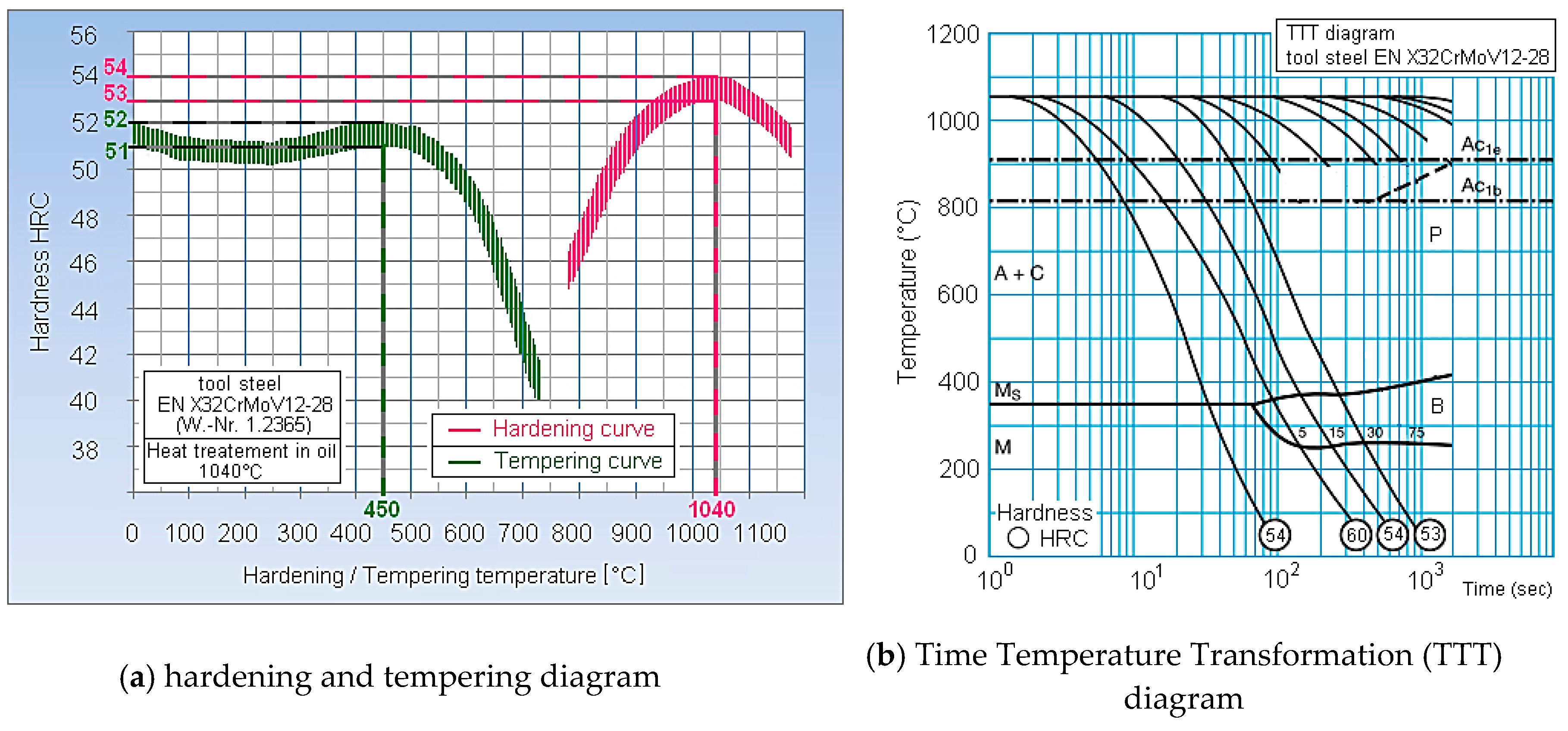
| EN X32CrMoV12-28 | 0.28–0.35 | 0.1–0.4 | 0.15–0.45 | 2.7–3.2 | 2.6–3.0 | 0.4–0.7 | 0.03 | 0.03 | 230 | 52 |
© 2017 by the authors. Licensee MDPI, Basel, Switzerland. This article is an open access article distributed under the terms and conditions of the Creative Commons Attribution (CC BY) license ( http://creativecommons.org/licenses/by/4.0/).
Share and Cite
Straka, L.; Corný, I.; Pitel’, J.; Hašová, S. Statistical Approach to Optimize the Process Parameters of HAZ of Tool Steel EN X32CrMoV12-28 after Die-Sinking EDM with SF-Cu Electrode. Metals 2017, 7, 35. https://doi.org/10.3390/met7020035
Straka L, Corný I, Pitel’ J, Hašová S. Statistical Approach to Optimize the Process Parameters of HAZ of Tool Steel EN X32CrMoV12-28 after Die-Sinking EDM with SF-Cu Electrode. Metals. 2017; 7(2):35. https://doi.org/10.3390/met7020035
Chicago/Turabian StyleStraka, L’uboslav, Ivan Corný, Ján Pitel’, and Slavomíra Hašová. 2017. "Statistical Approach to Optimize the Process Parameters of HAZ of Tool Steel EN X32CrMoV12-28 after Die-Sinking EDM with SF-Cu Electrode" Metals 7, no. 2: 35. https://doi.org/10.3390/met7020035
APA StyleStraka, L., Corný, I., Pitel’, J., & Hašová, S. (2017). Statistical Approach to Optimize the Process Parameters of HAZ of Tool Steel EN X32CrMoV12-28 after Die-Sinking EDM with SF-Cu Electrode. Metals, 7(2), 35. https://doi.org/10.3390/met7020035