Article

High Power Diode Laser (HPDL) for Fatigue Life Improvement of Steel: Numerical Modelling

Department of Engineering, University Niccolò Cusano, Via don Carlo Gnocchi 3, Rome 00166, Italy
*
Author to whom correspondence should be addressed.
Metals 2017, 7(10), 447; https://doi.org/10.3390/met7100447
Submission received: 18 September 2017 / Revised: 5 October 2017 / Accepted: 18 October 2017 / Published: 21 October 2017

Abstract

:
This paper deals with the improvement of fatigue life of AISI 1040 steel components by using a High Power Diode Laser (HPDL). First, the meaningfulness of each operational parameter was assessed by varying the experimental laser power and scan speed. After laser treatment, fatigue tests were performed to investigate the influence of laser processing parameters on the material resistance. The fatigue tests were carried out by using a rotating bending machine. Wöhler curves were obtained from the analysis of experimental results. Second, in the light of experimental findings, a 3D transient finite element method for a laser heat source, with Gaussian energy distribution, was developed to predict the temperature and the depth of the heat affected zone on the workpiece. The model allows us to understand the relationship between the laser treatment parameters and the fatigue enhancement of the components. HPDL was found to significantly increase the fatigue life of the irradiated workpieces, thus revealing its suitability for industrial applications.

1. Introduction

The improvement of mechanical strength and fatigue life of structural components is one of the most important objective to be achieved in order to satisfy the stringent requirements of today’s designers and producers [1,2,3]. Designing, monitoring, and providing innovative technological solutions aimed at improving the mechanical properties and in particular the fatigue life of steel components are therefore of fundamental importance [4,5]. During the last decades, many different approaches to improve the fatigue life of steels were proposed, i.e., heat and mechanical treatments, surface alloying, overlying coatings, etc. Among them, surface treatments on steel components have different applications in many technological domains. Generally, they are applied to obtain an improvement of hardness, wear resistance, and corrosion properties. These treatments permit steel components to meet the demand of high performance (load, pressure, wear, etc.) of the industrial world [6]. However, these processes, while having many advantages, are often expensive, time consuming, and do not allow a selective treatment of small portions of the component. In this respect, the use of lasers for the thermal surface treatment of steel components has appeared as an innovative solution since it offers selectivity, leaving areas not directly exposed to laser radiation unaltered, making process control very easy and facilitating manipulation [7,8,9,10]. A high power laser beam may be directed onto a surface using very precise multi-axis handling systems. A laser makes it possible to achieve extremely localized heating areas, remaining the bulk of the workpiece at the lower temperatures. The low temperature mass of the workpiece act as a heat sink during the cooling phase, allowing cooling rates of 103–104 K/s suitable for the martensitic transition, resulting in increased wear and fatigue resistance of the component [11]. Moreover, when compared to other solutions, laser hardening causes little deformation of the part thanks to precise, controlled, and low heat input, thus virtually eliminating post-machining processes. In addition, laser sources can be applied to a wide range of materials [12,13,14,15,16]. All cast iron, medium-carbon steel, and tool steel are amenable to the laser hardening process [11], and even low carbon steels are amenable because of the rapid heating and cooling rates generated by the laser radiation [17]. On the other hand, the main disadvantage compared to conventional technologies is found with the effects of back tempering induced by multiple passes. In fact, a multi-pass hardening process is characterized form back-tempering phenomena. Every laser track re-heats the area previously heated, inducing a transformation of the martensite into tempered martensite characterized by lower hardness. Thus, the back tempering phenomena leads to a lack of uniformity of the surface mechanical properties [8,18]. A High Power Diode Laser (HPDL), different from other sources, is well suited to surface hardening. In fact, the HPDL beam profile ensures a uniform heating of the treated surface due to its characteristics: top-hat in the slow axis direction and Gaussian in the fast axis direction. The shape of the spot is typically rectangular or elliptical [19]. Finally, HPDLs have important advantages in terms of energy consumption, compactness, endurance, and running costs, making them suitable and appealing for many industrial applications [20].
To exploit the tremendous application potential of High Power Diode Lasers, research and development programs have been undertaken since 1994 [19,20]. Pashby et al. [21] reported the use of an HPDL for surface-hardening of a plain carbon and an alloy steel, investigating the relationships between laser power and processing speed. They achieved a constantly hardened depth and demonstrated the technical capability of diode lasers in surface hardening. Liu et al. [6] treated grey cast iron surface with diode laser to improve the hardness and wear resistance of the surface. They found that residual compressive stresses observed at the surface greatly enhance fatigue life and hardness. Fly et al. [22] treated low carbon steel by means of a low-power laser. Even in this case, an improvement in fatigue behavior was observed.
In laser surface treatments, obtaining required hardness while minimizing thermal deformation is critical because structural components require high precision. Unfortunately, satisfying both the aforementioned requirements is a challenging task, and a good predictive model can significantly reduce time and costs in finding optimal process conditions. For this reason, extensive research has been carried out to either develop predictive models or uncover relationships between process parameters and process outcomes [23,24]. To have the possibility to carry out a full analysis of thermal treatment, it is necessary to have proper mathematical and numerical models that can provide information about instantaneous temperature fields, the change in time of fractions of particular phase proportions of the material, instantaneous stress distributions, and residual stresses. Currently, numerical methods are leading in the modelling of technological processes, allowing us to analyse complex shapes with any initial and boundary conditions. Moreover, numerical modelling is characterized by high elasticity with respect to numerical algorithm development and the possibility to consider variable thermo-physical parameters of the analysed problem [25,26,27,28].
In the present investigation, a High Power Diode Laser was used to improve the fatigue life of AISI 1040 steel workpieces. The interaction between laser source and steel surface was looked into by varying the laser operational parameters (i.e., laser power and scan speed). Laser treatment was performed by simultaneously rotating and translating the substrate under a stationary laser head to generate a helical scanning pattern. The effectiveness of the laser treatment was studied by rotating bending fatigue tests and microscopic analysis.
In the light of experimental findings, a 3D transient finite element method for a laser heat source, with a Gaussian energy distribution, was developed to predict the temperature and the depth of the Heat Affected Zone (HAZ) on the AISI 1040 steel workpiece. The thermo-mechanical problem was solved sequentially in two phases. First, a transient thermal analysis was carried out in order to obtain the temperature distribution, which was used as input for the following static analysis. The experimental investigation demonstrated that HPDL surface treatment significantly increase the fatigue life of the irradiated workpieces, thus revealing its suitability for industrial applications. Furthermore, the simulation results turned out to be in good agreement with the experimental data.

2. Experimental

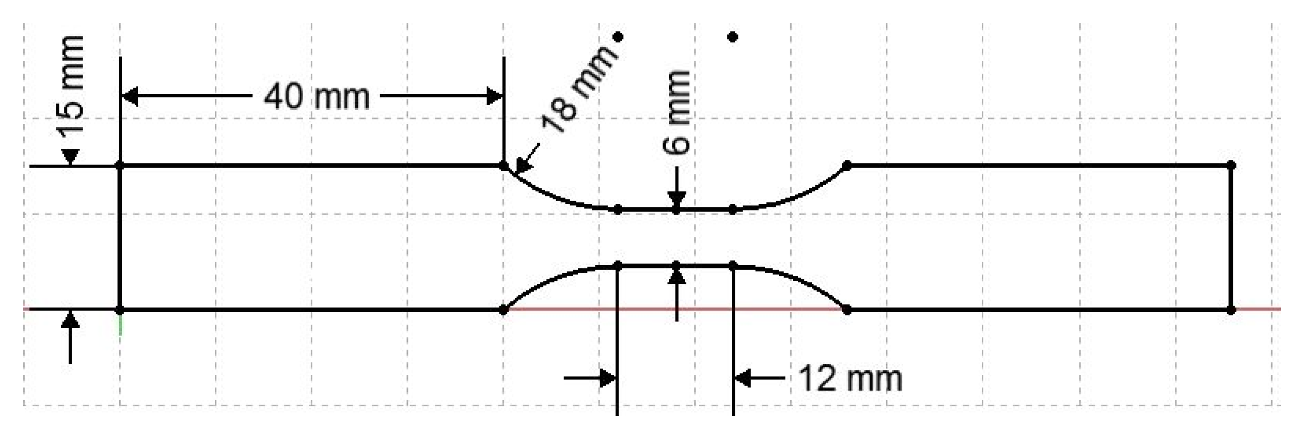
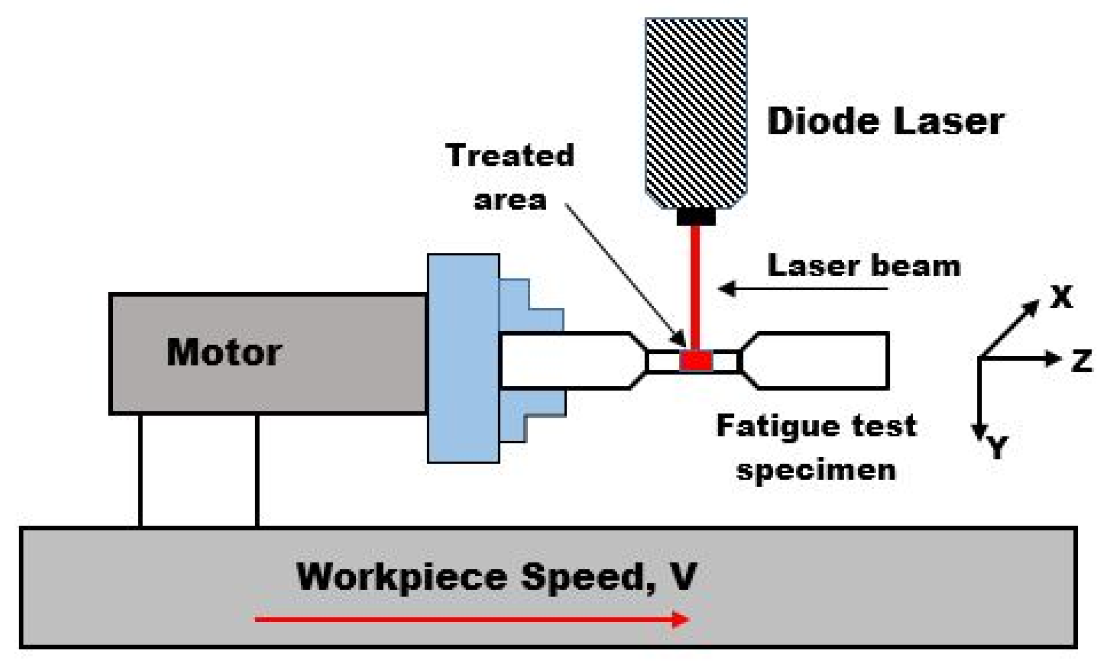
2.1. Material and Methods
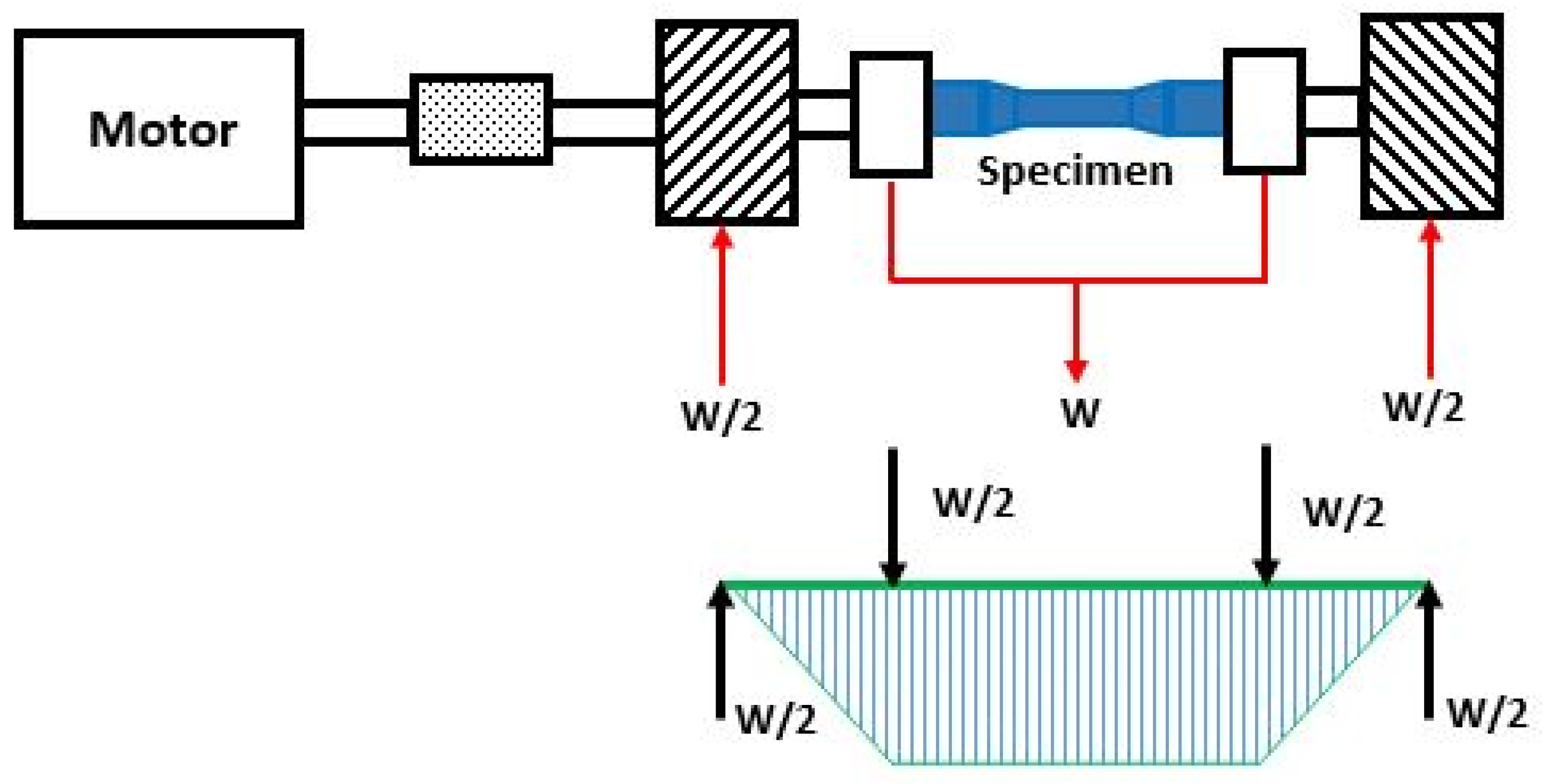
A low carbon steel (AISI 1040) was chosen as the starting material due the suitability for thermal hardening treatments [17,29] and since it is commonly used in structural components as gears, shafts, axles, bolts, studs, couplings, and cold headed parts. The mechanical properties and chemical composition of the steel are reported in Table 1. The thermal properties are reported in Table 2. Starting from 2 m rods, 75 samples were cut with the geometry reported in Figure 1 (Φ 15 × 116 mm). The surface of the section, with diameter 6 mm, was machined with the same operational conditions, using a milling machine with medium finishing inserts. Surface hardening thermal treatments were performed using an HPDL (Rofin-Sinar model DL015, Plymouth, MI, USA) with a maximum peak power of 1.5 kW, wavelength of 940 nm and elliptical spot of 0.6 mm along the minor axis and 1.9 mm along the major axis. During the laser thermal treatments, the samples were held on a CNC turning device (DENFORD, Brighouse, West Yorkshire, UK) and processed by rotating them under the laser source as reported in Figure 2. For protection and insulation purposes, an inert gas flow of Argon was directed to the surface of the sample. Figure 2 reports a schematization of the system used.
Surface laser treatments followed the experimental schedule reported in Table 3. The experimental factors investigated were laser power and scan speed (peripheral speed calculated as the product of the rotational speed and the radius of the small section). Focus and number of passes were fixed respectively at 0 and 1. For each condition investigated (that is, 25), the rotation speed and the beam feed were properly chosen to ensure no overlap of the laser treatment. All the tests were replicated three times (75 experimental tests). After that, the area treated was characterized in terms of variations in the extent of the hardened area (i.e., (Heat Affected Zone) HAZ).

2.2. Fatigue Tests

A four-point rotating bending machine was used to carry out the fatigue tests, as shown in Figure 3. The samples were loaded with alternate cycles of tensile and compressive stresses as they were simultaneously bent and rotated. Loads from 10 to 16 kg were applied during the tests, corresponding to an alternating stress (σMAX) in the range of approximately 320 to 460 MPa.

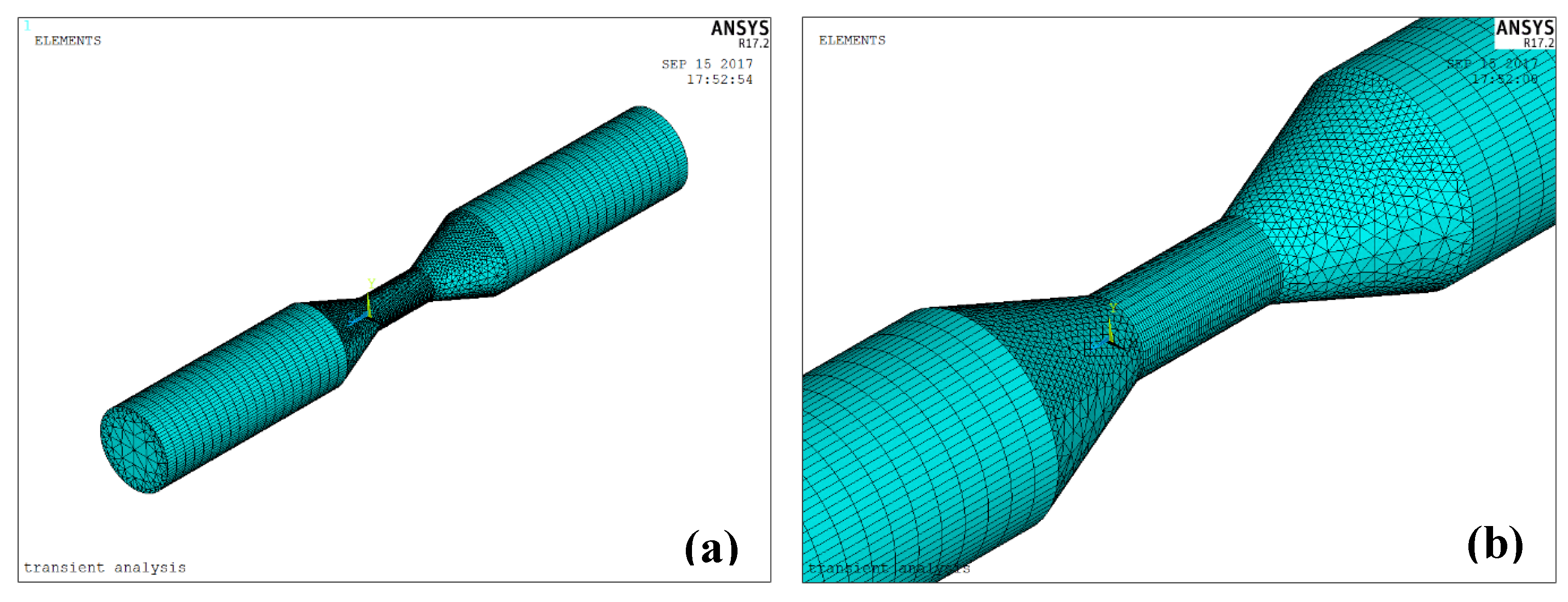
2.3. Numerical Model

A thermo-mechanical numerical simulation was performed to describe the hardening process on the fatigue specimens. ANSYS code (ANSYS, Inc., version 17.2, Canonsburg, PA, USA) was used for the numerical model definition. The simulation first step was the thermal analysis that was carried out by using SOLID70 thermal elements. In the second step of the simulation, starting from the thermal solution, the thermal elements were converted into SOLID185 structural elements. At the end of the simulation, the radial displacement, strain and stress of specimen were evaluated, in order to have the profile of the deformed specimen [30]. An axially symmetric object (standard tensile test specimen), 15 mm in outer diameter, 6 mm in inner diameter, and 116 mm in length, was subjected to the simulation as reported in Figure 4, where the meshes used in both thermal and mechanical calculations are presented. As shown in Figure 4, a finer mapped mesh was used in the area subjected to higher temperatures being directly located below the incident laser heat flux. This approach permits to reduce modelling and solution times.
The laser heating was modelled as thermal load by using a heat flux over an approximated elliptical spot of 3.8 × 1.2 mm2. The laser beam power of 200 W was obtained by imposing a flux density of about 43.86 W/mm2. The moving laser beam has a Gaussian distribution of heat flux. The model contains overall about 18,000 nodes and 36,000 elements. The starting environmental temperature was 20 °C. The material properties used in the Finite Element Method (FEM) model are reported in Table 1 and Table 2.
The numerical model was calibrated using the following experimental scenario: laser power 200 W and scan speed 16 mm/s. In this experimental condition, thermocouples were used to obtain the experimental temperature profiles over time in three different tests. All the experimental thermal trends were compared with the numerical response of the model, as shown in Figure 5. The convective coefficients were chosen to have the best fitting between the experimental and numerical temperature profiles.

3. Results and Discussion

Results show that among the laser power values examined (see Table 3), the treatments at 200 W highlight the best performance. These process conditions lead to a change in substrate properties without melting phenomena, with scan speed in the range 16 to 20 mm/s. On the contrary, the treatment conditions at lower laser power (100–150 W) did not lead to significant changes in the morphology of the analysed substrates. In particular, any grain structure modification was observed. Increasing the power to 250 or 300 W, independently from the scanning speed, surface melting of the specimen was observed. These results are in good agreement with literature results [31] and are supported by the results reported in Figure 6. It reports life cycles of the steel specimen vs. the laser scan speed treatment obtained fixing the laser power at the value of 200 W. The laser scan speed was found to be an influential factor in the process. Increasing the laser scan speed, the life of the specimen increases. The amount of thermal energy the steel can absorb during its treatment decreases, and the process reaches the condition in which it is possible to have a martensitic transaction. The curves trend indicates that there is a significant increasing of the fatigue life in the specimen treated with the diode laser. More importantly, the nose of the Wöhler curve for the laser-treated substrates is reached at a number of cycles that is almost twice that of the untreated substrates (NT label in Figure 6). These results are also confirmed in literature in the study made from Guarino et al. [18] and are also in good agreement with data reported in the pertinent literature [6,19]. The increment of the fatigue life can be attributed to the formation of a superficial annealed martensitic structure due to thermal phenomena induced by the laser treatment. The subsequent laser scan causes a further heat treatment which leads to a slight annealing of the steel (i.e., back tempering phenomenon) [29,32]. This phenomenon is clearly reported in Figure 7, which shows a cross section of the steel specimen heat-treated at 200 W and 20 mm/s in laser power and scan speed, respectively. In the latter figure, it is possible to observe that the martensitic transition reaches a thickness of about 180 µm.
Laser treatments were carried out in order to maintain a constant laser scan speed. Due to the varying section of the sample, its rotating speed was accordingly changed when moving from the largest section zone of the substrate to the smallest one. It is worth to note that all the parameters were chosen to avoid or at least limit the overlapping phenomenon. As shown in Figure 8, each laser treatment started at point A, where the diameter of the specimen is the largest, and continued along the surface of the substrate passing to point B, varying the laser scan speed as mentioned before because of the decreasing of the diameter. Between the points B and C, the diameter is constant, as it is the laser scan speed. Finally, passing from C to point D, the diameter increases, and the laser scan speed is adjusted accordingly. Table 4 reports the interaction time between the laser beam and the specimen at different scan speed obtained along the constant section (i.e., from B to C). In particular, the lower the scan speed the higher the interaction time. It must be noticed that an excessive treatment time lead to the back-tempering phenomenon while a too-short treatment time does not guarantee sufficient heat input required for the martensitic transition.
Figure 9 shows the fatigue tests results in terms of number of cycles vs. the square root of laser interaction time with the substrate. The latter term, which is suggested to be proportional to the laser power, as reported in literature [12,32], allows a better understanding of the dependence of the fatigue life from the laser power itself. As expected, the number of cycles decreases as the laser power increases (Figure 9). It has been seen, from the experimental model regression, that there is a dependence of fatigue life endurance from the treatment time according to the following regression model:
C N = 6.1 × 10 4 t + 2.5 × 10 5 ,
where CN is the cycle number and t is the treatment time. The R2 is 0.95.

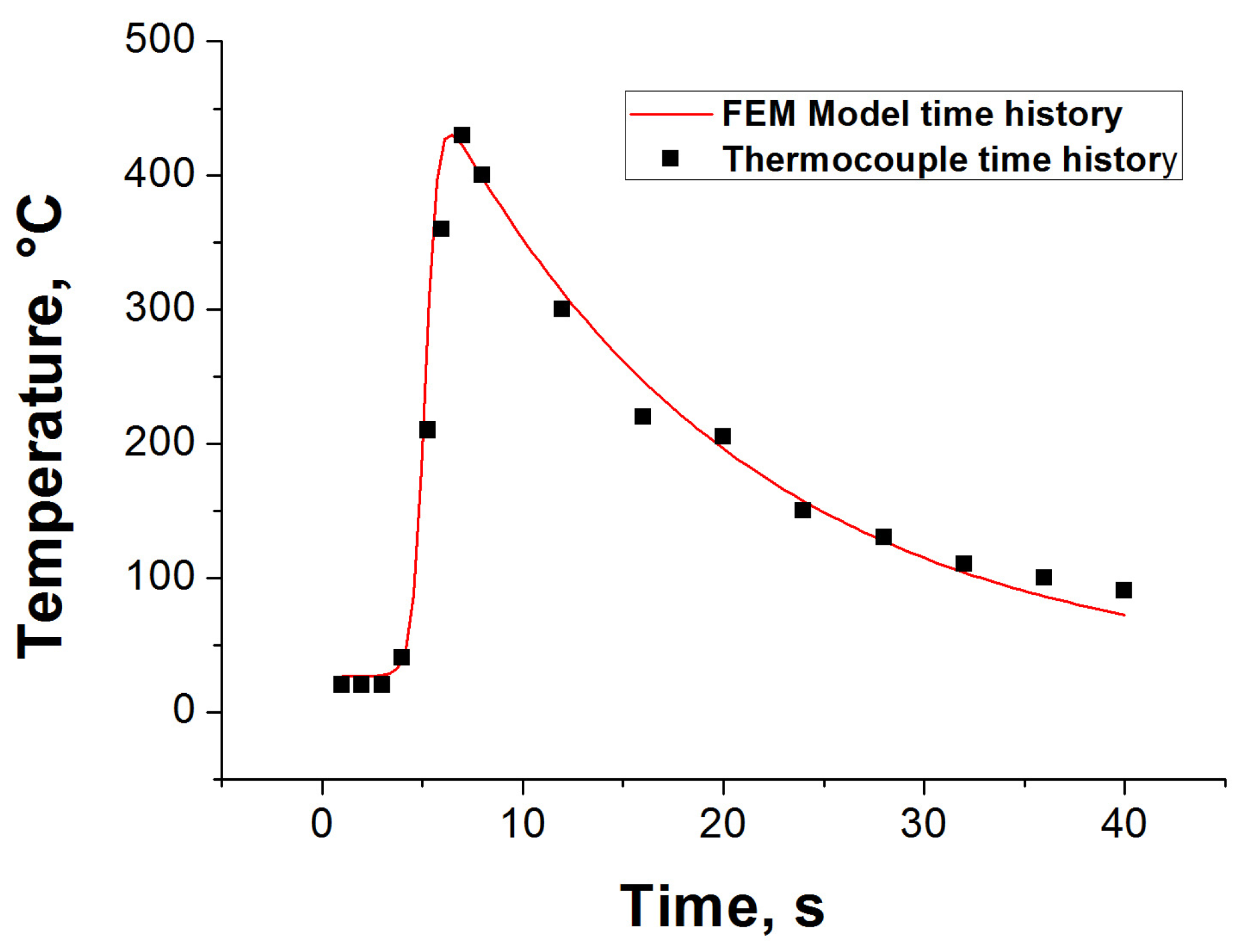
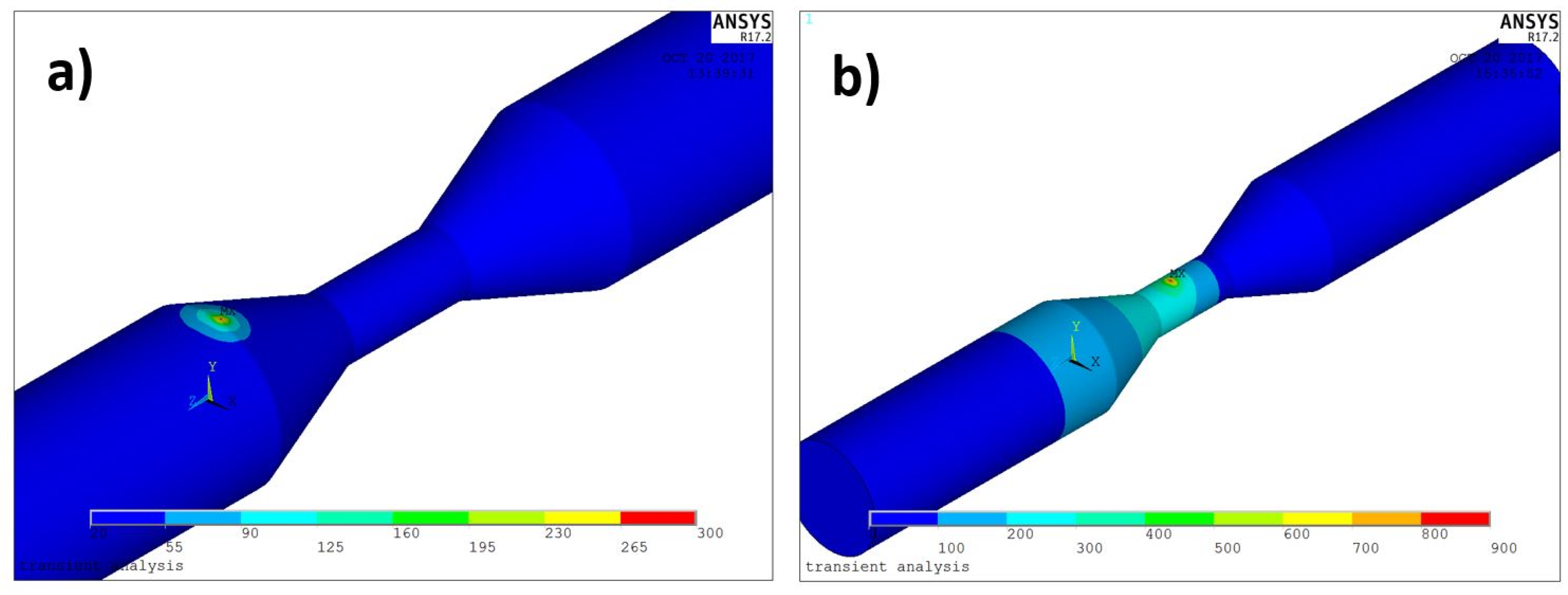
3.1. Numerical Simulation Results

Figure 10 shows the temperature over the time for three different points (A, B, C) in a small section of the specimen during the laser treatment process. The peak temperatures were observed in proximity of the heat source position (point A). A high temperature gradient can be observed during the heating step, which is followed by the cooling phenomenon after the maximum temperature is reached.
Figure 11 shows the temperature map evolution during the hardening process simulation at two different times: 1.5 and 16 s. The laser scan speed was set at 20 mm/s. The maximum temperature reached is about 850 °C, lower than the melting point of the material (1515 °C). This scenario clearly indicates that all examined points are outside the fusion “window” and in the right thermal conditions for the hardening transition.
As showed in Figure 12, the FEM model allows identifying the substrate thickness of the workpiece with a temperature profile of greater than 600 °C. This area corresponds to the HAZ zone where there are the thermal conditions for the martensitic transition. Figure 12 shows a good agreement between the simulation (Figure 12a) and experimental results (Figure 12b) being, in both cases, the hardened thickness of about 180 μm. In particular, the simulation predicts a slightly shallower depth for all the scan speed investigated. It must be noticed that the fitting between the numerical model and the experimental data is characterized by a mean absolute error of ~7%. The matching between the FEM model and the experimental data can therefore be considered very good, even if it is compared with data available in the literature [11,24,33].
The reliability of the developed FEM model is also confirmed by considering the data that the simulation can predict in terms of max stress vs. cycle number. In the experimental test, sample rupture is taken when there is a strong reduction in the stress level compared to the stabilized cycles. In numerical simulation, this method is not suitable for predicting sample failure. However, the model is able to make a good prediction of the maximum stress vs number of cycles providing a useful support for the experimental investigation.

4. Conclusions

A High Power Diode Laser source was adopted to investigate its capability to increase the fatigue life of AISI 1040 steel samples by the thermal-surface-hardening process. Analysis of the microstructure of the specimens revealed two main different areas: (i) a topmost area characterized by a homogenous distribution of the annealed martensite and (ii) an unaltered underling area made of ferrite and perlite structure. From the experimental results, the following conclusions can be drawn:
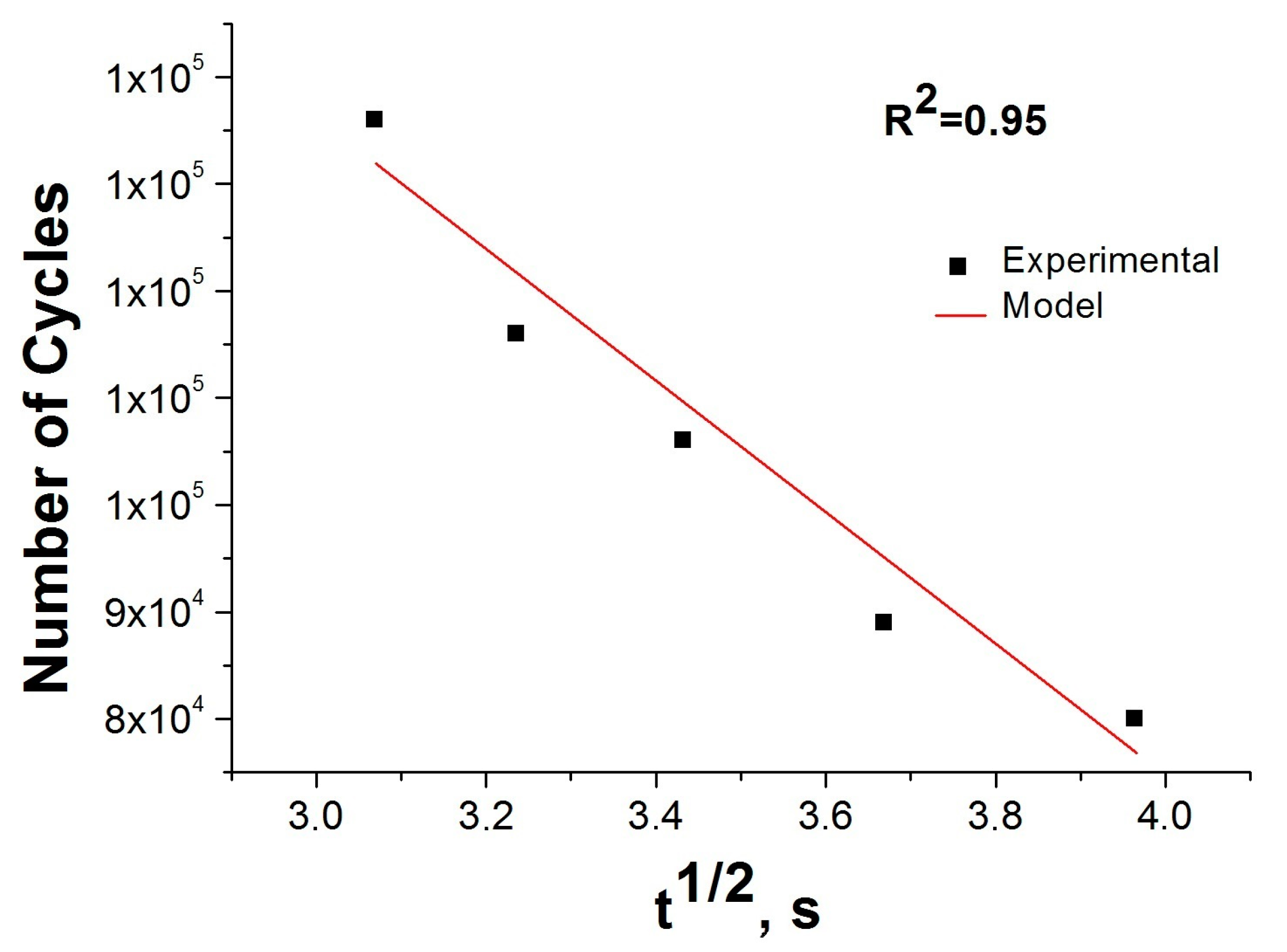
  • The most suitable thermal conditions (i.e., change in structure without melting phenomena) are reached with a single laser scan by using a laser power of 200 W and a scan speed of 20 mm/s. Lower laser power has no effect, higher laser power causes the surface melting. In both cases, the result is independent of the scan speed adopted.
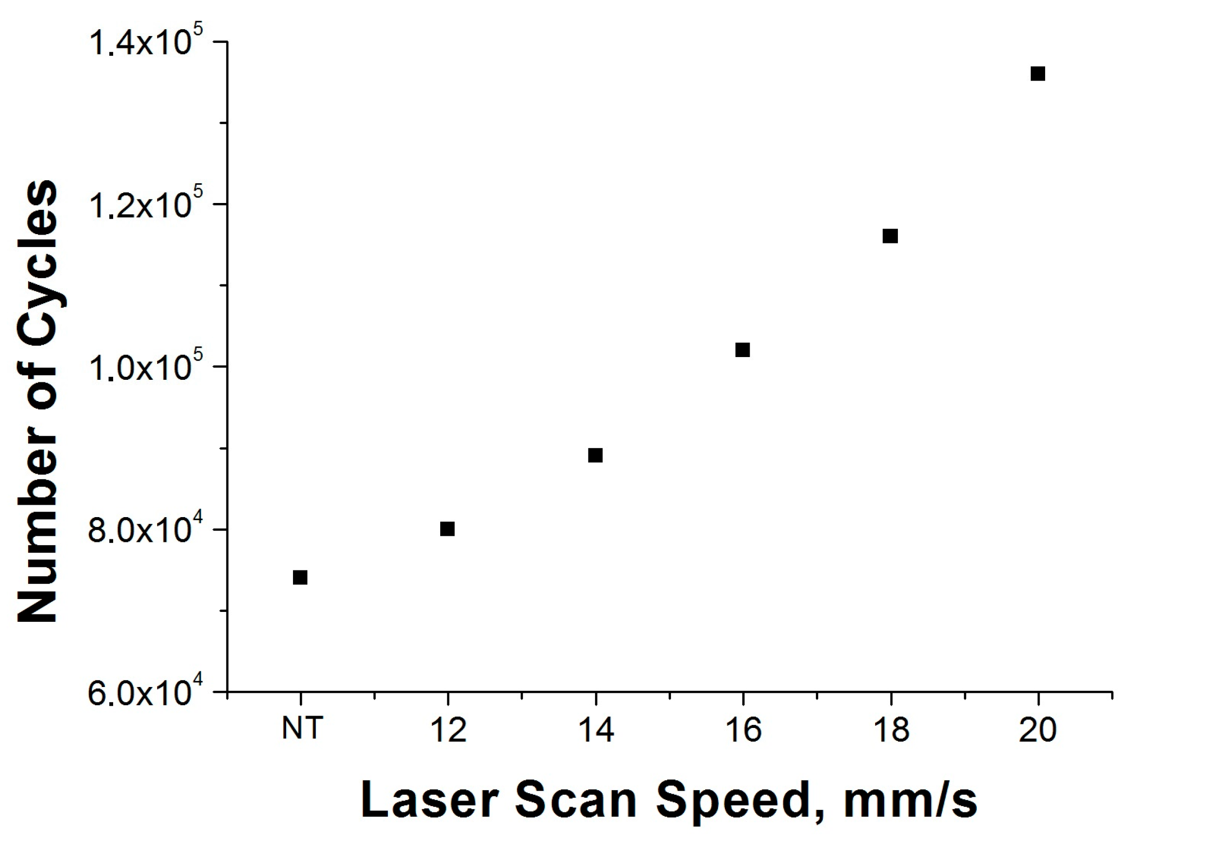
  • The laser thermal surface treatment increases the fatigue life of treated material with respect to the untreated material.
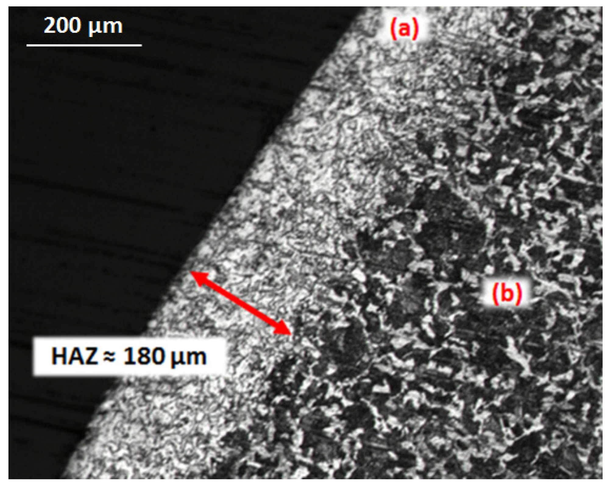
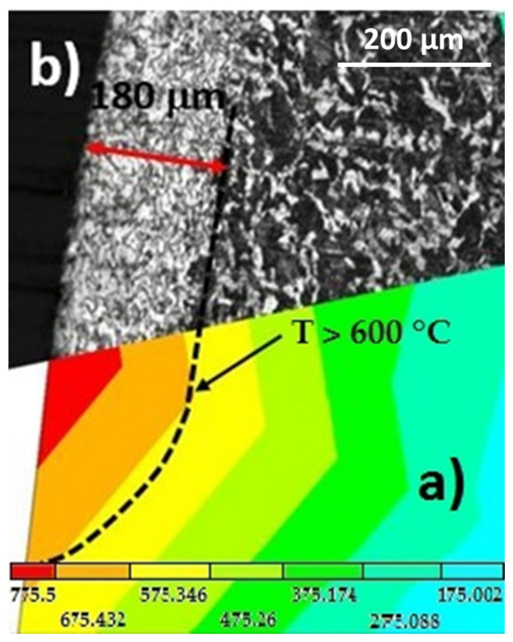
  • The extent of the Heat Affected Zone was consistently found to depend on the laser fluency. An excessive treatment time or a too-high laser power inhibit the thermal conditions required for the martensitic transition. This is due to the excessive heat input supplied to the sample.
Finally, in the light of experimental findings, a Finite Element Method model was developed and validated with the aim to have a suitable tool for laser surface hardening process simulation. The comparison of experimental and numerical results revealed a good correlation for both the extent of the Heat Affected Zone and fatigue life with an error of ~7% and ~4%, respectively. The experimental results show the great potential of High Power Diode Laser for the surface hardening of steel substrates, and the simulations reveal the capability of the Finite Element Method solutions to be very helpful in predicting, controlling, and managing the laser surface hardening processes.

Acknowledgments

The authors gratefully acknowledge the CIRTIBS Research Centre of the University of Naples Federico II and the Department of Enterprise Engineering of University of Rome Tor Vergata for providing the equipment, the materials, and the technical support necessary to develop this research work.

Author Contributions

Stefano Guarino conceived and designed the experiments; Stefano Guarino and Gennaro Salvatore Ponticelli performed the experiments, analyzed the data and wrote the paper. Both authors have read and approved the final manuscript.

Conflicts of Interest

The authors declare no conflict of interest.

References

  1. Milella, P.P. Fatigue and Corrosion in Metals; Springer: Berlin, Germany, 2013. [Google Scholar]
  2. Norske Veritas, D. Fatigue Design of Offshore Steel Structures; Tapir: Oslo, Denmark, 1985. [Google Scholar]
  3. Stalios, A. Metallurgy made in and for Europe; Publications Office of the European Union: Luxembourg, 2014. [Google Scholar]
  4. Santos, L.M.S.; Ferreira, J.A.M.; Jesus, J.S.; Costa, J.M.; Capela, C. Fatigue behaviour of selective laser melting steel components. Theor. Appl. Fract. Mech. 2016, 85, 9–15. [Google Scholar] [CrossRef]
  5. Yıldırım, H.C. Recent results on fatigue strength improvement of high-strength steel welded joints. Int. J. Fatigue 2017, 101, 408–420. [Google Scholar] [CrossRef]
  6. Liu, A.; Previtali, B. Laser surface treatment of grey cast iron by high power diode laser. Phys. Procedia 2010, 5, 439–448. [Google Scholar] [CrossRef]
  7. Vollertsen, F.; Partes, K.; Meijer, J. State of the Art of Laser Hardening and Cladding. In Proceedings of the Third International WLT-Conference on Lasers in Manufacturing, Munich, Germany, 14–17 June 2005. [Google Scholar]
  8. Lakhkar, R.S.; Shin, Y.C.; John, M.; Krane, M. Predictive modeling of multi-track laser hardening of AISI 4140 steel. Mater. Sci. Eng. A 2008, 480, 209–217. [Google Scholar] [CrossRef]
  9. Jiang, J.; Xue, L.; Wang, S. Discrete laser spot transformation hardening of AISI O1 tool steel using pulsed Nd: YAG laser. Surf. Coatings Technol. 2011, 205, 5156–5164. [Google Scholar] [CrossRef]
  10. Barletta, M.; Gisario, A.; Guarino, S. Hybrid forming process of AA 6108 T4 thin sheets: Modelling by neural network solutions. Proc. Inst. Mech. Eng. Part B 2009, 223, 535–545. [Google Scholar] [CrossRef]
  11. Nath, A.K.; Gupta, A.; Benny, F. Theoretical and experimental study on laser surface hardening by repetitive laser pulses. Surf. Coatings Technol. 2012, 206, 2602–2615. [Google Scholar] [CrossRef]
  12. Guarino, S.; Ponticelli, G.S.; Giannini, O.; Genna, S.; Trovalusci, F. Laser milling of yttria-stabilized zirconia by using a Q-switched Yb: YAG fiber laser: Experimental analysis. Int. J. Adv. Manuf. Technol. 2017, 1–13. [Google Scholar] [CrossRef]
  13. Umer, U.; Mohammed, K.; Al-Ahmari, A. Multi-response optimization of machining parameters in micro milling of alumina ceramics using Nd: YAG laser. Measurement 2017, 95, 181–192. [Google Scholar] [CrossRef]
  14. Xu, Y.; Peng, Y.; Dearn, K.D.; You, T.; Geng, J.; Hu, X. Fabrication and tribological characterization of laser textured boron cast iron surfaces. Surf. Coatings Technol. 2017, 313, 391–401. [Google Scholar] [CrossRef]
  15. Romoli, L.; Tantussi, F.; Fuso, F. Laser milling of martensitic stainless steels using spiral trajectories. Opt. Lasers Eng. 2017, 91, 160–168. [Google Scholar] [CrossRef]
  16. Sciti, D.; Trucchi, D.M.; Bellucci, A.; Orlando, S.; Zoli, L.; Sani, E. Effect of surface texturing by femtosecond laser on tantalum carbide ceramics for solar receiver applications. Sol. Energy Mater. Sol. Cells 2017, 161, 1–6. [Google Scholar] [CrossRef]
  17. Guarino, S.; Barletta, M.; Afilal, A. High Power Diode Laser (HPDL) surface hardening of low carbon steel: Fatigue life improvement analysis. J. Manuf. Process. 2017, 28, 266–271. [Google Scholar] [CrossRef]
  18. Grum, J. Comparison of different techniques of laser surface hardening. J. Achiev. Mater. Manuf. Eng. 2007, 24, 17–25. [Google Scholar]
  19. Kennedy, E.; Byrne, G.; Collins, D.N. A review of the use of high power diode lasers in surface hardening. J. Mater. Process. Technol. 2004, 155–156, 1855–1860. [Google Scholar] [CrossRef]
  20. Skvarenina, S.; Shin, Y.C. Predictive modeling and experimental results for laser hardening of AISI 1536 steel with complex geometric features by a high power diode laser. Surf. Coatings Technol. 2006, 201, 2256–2269. [Google Scholar] [CrossRef]
  21. Pashby, I.R.; Barnes, S.; Bryden, B.G. Surface hardening of steel using a high power diode laser. J. Mater. Process. Technol. 2003, 139, 585–588. [Google Scholar] [CrossRef]
  22. Fly, D.E.; Black, J.T.; Singleton, B. Low power laser heat treatment to improve fatigue life of low carbon steel. J. Laser Appl. 1996, 8, 89–93. [Google Scholar] [CrossRef]
  23. Oh, S.; Ki, H. Prediction of hardness and deformation using a 3–D thermal analysis in laser hardening of AISI H13 tool steel. Appl. Therm. Eng. 2017, 121, 951–962. [Google Scholar] [CrossRef]
  24. Liverani, E.; Sorgente, D.; Ascari, A.; Scintilla, L.D.; Palumbo, G.; Fortunato, A. Development of a model for the simulation of laser surface heat treatments with use of a physical simulator. J. Manuf. Process. 2017, 26, 262–268. [Google Scholar] [CrossRef]
  25. Domański, T.; Bokota, A. Numerical Analysis of Phenomena During Progressive Hardening of Tool Steel Elements for Cold Work. Procedia Eng. 2017, 177, 70–77. [Google Scholar] [CrossRef]
  26. Kang, S.-H.; Im, Y.-T. Finite element investigation of multi-phase transformation within carburized carbon steel. J. Mater. Process. Technol. 2007, 183, 241–248. [Google Scholar] [CrossRef]
  27. Coret, M.; Combescure, A. A mesomodel for the numerical simulation of the multiphasic behavior of materials under anisothermal loading (application to two low-carbon steels). Int. J. Mech. Sci. 2002, 44, 1947–1963. [Google Scholar] [CrossRef]
  28. Huiping, L.; Guoqun, Z.; Shanting, N.; Chuanzhen, H. FEM simulation of quenching process and experimental verification of simulation results. Mater. Sci. Eng. A 2007, 452–453, 705–714. [Google Scholar] [CrossRef]
  29. Gisario, A.; Barletta, M.; Boschetto, A. Characterization of laser treated steels using instrumented indentation by cylindrical flat punch. Surf. Coatings Technol. 2008, 202, 2557–2569. [Google Scholar] [CrossRef]
  30. Incropera, F.P.; DeWitt, D.P.; Bergman, T.L.; Lavine, A.S. Fundamentals of Heat and Mass Transfer; John Wiley & Sons: Hoboken, NJ, USA.
  31. Lusquiños, F.; Conde, J.C.; Bonss, S.; Riveiro, A.; Quintero, F.; Comesaña, R.; Pou, J. Theoretical and experimental analysis of high power diode laser (HPDL) hardening of AISI 1045 steel. Appl. Surf. Sci. 2007, 254, 948–954. [Google Scholar] [CrossRef]
  32. Gisario, A.; Barletta, M.; Conti, C.; Guarino, S. Springback control in sheet metal bending by laser-assisted bending: Experimental analysis, empirical and neural network modelling. Opt. Lasers Eng. 2011. [Google Scholar] [CrossRef]
  33. Martínez, S.; Lesyk, D.; Lamikiz, A.; Ukar, E.; Dzhemelinsky, V. Hardness Simulation of over-tempered Area During Laser Hardening Treatment. Phys. Procedia 2016, 83, 1357–1366. [Google Scholar] [CrossRef]
Figure 1. Specimen geometry.
Metals 07 00447 g001
Figure 2. High Power Diode Laser (HPDL) system.
Metals 07 00447 g002
Figure 3. Four-point rotating bending machine.
Metals 07 00447 g003
Figure 4. Finite element mesh used in thermo-mechanical analysis: (a) general view; (b) local magnification.
Metals 07 00447 g004
Figure 5. Model calibration curve. Laser power = 200 W and Scan speed = 16 mm/s.
Metals 07 00447 g005
Figure 6. Number of cycles vs. laser scan speed (Laser power = 200 W). NT refers to the untreated samples.
Metals 07 00447 g006
Figure 7. Micrography of a laser hardened cross-section: transition from: (a) martensitic structure to (b) ferrite and perlite structure (Laser power = 200 W and Scan speed = 20 mm/s).
Metals 07 00447 g007
Figure 8. Laser path: AB and CD are characterized by a varying section, while BC has a constant section.
Metals 07 00447 g008
Figure 9. Number of cycles vs. laser interaction time (Scan speed = 20 mm/s).
Metals 07 00447 g009
Figure 10. Calculated temperatures for nodes A, B, and C over time.
Metals 07 00447 g010
Figure 11. Temperature distribution during the hardening process of AISI 1040 steel specimen at two different times: (a) t = 1.5 s; (b) t = 16 s.
Metals 07 00447 g011
Figure 12. Heat Affected Zone (HAZ) in (a) numerical and (b) experimental model (Laser power = 200 W and Scan speed = 20 mm/s).
Metals 07 00447 g012
Table 1. Mechanical properties and chemical composition of AISI 1040.
PropertyValueComposition (wt %)Value
Rm (Mpa)670C0.37–0.44
E (GPa)200Mn0.50–0.80
ν0.3Si0.15–0.40
HRC13P and S≤ 0.035
Table 2. Thermal properties of AISI 1040.
Temperature (°C)Heat capacity (J/kgK)Thermal Conductivity (W/mK)
0–10048650.7
20051548.1
30056945.7
40058641.7
50064938.2
60070833.9
70077030.1
Table 3. Experimental factors
FactorsValues
Laser power (W)100150200250300
Scan speed (mm/s)1214161820
Table 4. Interaction time and fatigue test results. NT refers to the untreated sample.
FactorsValues
Laser scan speed (mm/s)NT1214161820
Interaction time (s)015.7113.4611.7810.479.42
Interaction   time (s1/2)03.963.663.433.233.06
Number of cycles69,50078,00087,000104,000118,000137,500

