1. Introduction
Carbon nanotubes (CNTs), including multi-walled CNTs and single-walled CNTs, have attracted great attention in materials science since the landmark report by Iijima in 1991 [
1]. Due to the outstanding structural and physical properties, such as large aspect ratios, high strength, and high electrical/thermal conductivities, CNTs are regarded as promising reinforcements for composites [
2]. In the past decade, increasing attention was paid to CNT reinforced metal matrix composites (MMCs), which were expected as next-generation strong materials [
3]. Special interests were paid to aluminum (Al) matrix composites (AMCs) because their high specific strength, high conductivities, and anti-corrosive properties made them promising structural materials in aerospace, automobile, and sports industries [
4].
To achieve high load transfer efficiency [
5] in CNT–Al composites, suitable processing approaches should be explored. A homogeneous CNT dispersion in composites is the precondition, because there is little bonding between matrix and the CNTs inside CNT clusters, which is detrimental for effective load transfer [
6]. To overcome the problems of CNT agglomeration, some novel methods, such as the in-situ grown method [
7], flake powder metallurgy [
8], friction stir welding [
9], and solution ball milling (SBM) [
10], have been recently developed. Afterward, how to effectively consolidate CNT–Al powder mixtures to bulk materials became a concentrated topic. To make most use of CNTs, optimal composite structures are demanded for the consolidation process. Among the diverse microstructures, a high relative density is the first consideration, because it is the prime requirement for effective CNT–Al bonding in CNT–Al composites fabricated by powder metallurgy. There are a number of candidates for consolidating, for example, casting [
11], rolling [
12], extrusion [
13], sintering [
14], and a combination of sintering and extrusion [
15]. Among them, sintering is a promising one, mainly because of the comparatively low processing temperature, flexibility, and low cost.
Spark plasma sintering (SPS) is an advanced sintering technique where a pulsed direct current is applied to pass through the powder compact. Compared with conventional sintering techniques, SPS can produce higher sample densities (near full density) under low-temperature conditions [
16]. It is a significant advantage in those powder systems where grain growth or severe reactions had to be avoided. For example, a severe interfacial reaction between CNTs and Al, happening at a high processing temperature near the melting point of Al, would ruin the structure of CNTs [
17]. Therefore, SPS has been popular for the consolidation of many advanced nanocomposite powder systems [
18]. A number of studies have also used the combination of SPS and extrusion to fabricate CNT–Al composites [
3,
5,
6,
10,
16,
19]. However, the applicability of SPS for fabricating high-performance composites is still unclear. To examine this issue, the understanding on the sintering behaviors of CNT–Al composites powders is required primarily.
In this study, SPS was applied to consolidate the CNT–Al composite powders containing 1 wt % well-dispersed CNTs. As other processing conditions were fixed, SPS temperature was varied at 700, 750, 800, 850, and 900 K (melting point of pure Al, Tm, is ~933 K). The microstructural and conductive properties of as-sintered CNT–Al composites were systematically characterized. It was found that a critical temperature (Tc) corresponded to the transformation of the sintering regime existed during the consolidation of pure Al and CNT–Al composite powders. The CNT addition led to the decreased sintering rate and ~50 K delay of Tc. However, at high SPS temperature of 900 K, CNT–Al composite had a high relative density and high electrical conductivity, which were similar to those of pure Al. The effect of the observed alumina impurity on sintering kinetic of CNT–Al composite powder was discussed.
2. Materials and Methods
In this study, a mechanical coating process was used to obtain homogeneous CNT dispersion in AMCs. Pure Al powders (99.9% purity, Kojundo Chemical Laboratory Co., Saitama, Japan) was first milled with 2 wt % stearic acid (process control agent) powders using a planetary ball milling machine. The powders were sealed in a ZrO2 jar together with ZrO2 milling balls in an argon gas atmosphere. The revolution speed was 200 rpm, and milling time was 240 min. The milled powder was heat-treated at 700 K for 30 min in a vacuum furnace to remove the stearic acid. The next step is to disperse CNTs on prepared flaky Al powder surface. Multi-walled CNT (Baytubes C150P, Bayer Material Science Co., Tokyo, Japan) was used in this study. Flaky Al powders bathed in isopropyl alcohol (IPA)-based solution with ~1 wt % zwitterionic surfactants and 1 wt % CNTs in a plastic bottle on a rocking ball milling machine for 120 min. ZrO2 milling balls were added to assist the coating of CNTs on flaky powders. The powder mixture was heat-treated at 700 K for 30 min in a vacuum furnace to remove the remained surfactants.
The obtained CNT–Al composite powders were then consolidated by SPS on a SPS system (SPS-1030S, SPS Syntex, Kawasaki, Japan) at various sintering temperatures of 700 K (0.75
Tm), 750 K, 800 K, 850 K, and 900 K (0.96
Tm) with a heating rate of 20 K·min
−1, and held at each temperature for 60 min at pressure of 30 MPa under vacuum of 5 Pa. Graphite container (42 mm in inner-diameter) and graphite punches (42 mm in diameter) were used to hold the powders. Before sintering, the powder compacts were pressed under 10 MPa for 5 s. After the holding stage, the SPS power was switched off, and the sintered samples were cooled down inside the chamber. The samples were taken out below 373 K. More details on the process can be found elsewhere [
20].
The morphology of Al powder, CNT powder, Al-CNT composite powder, and as-sintered CNT–Al composites were examined by field emission scanning electron microscopy (FE-SEM, JEM-6500F, JEOL, Tokyo, Japan). Before SEM observation, the as-sintered samples were mechanically polished and then deeply chemically etched using an acid solution with 25% HNO3, 15% HCl, 10% HF, and 50% H2O in volume. The microstructure of CNT–Al composites were also characterized by transmission electron microscopy (TEM, JEM-2010, JEOL, Tokyo, Japan), assisted with energy Dispersive Spectrum (EDS). The density of sintered samples were measured on an ELECTRONIC DENSIMETER device (MDS-300, ALFA MIRAGE CO., LTD., Osaka, Japan) based on the Archimedes’ method. Three density values were used to get an average value. The relative density was further estimated using density of Al and CNT as 2.7 and 2.0 g·cm−3, respectively. The electrical conductivity was measured by a portable eddy current tester (AutoSigma3000, Tokyo, Japan) with a testing probe size of 8 mm in diameter. Thirty values were obtained at different positions to get an average conductivity.
3. Results
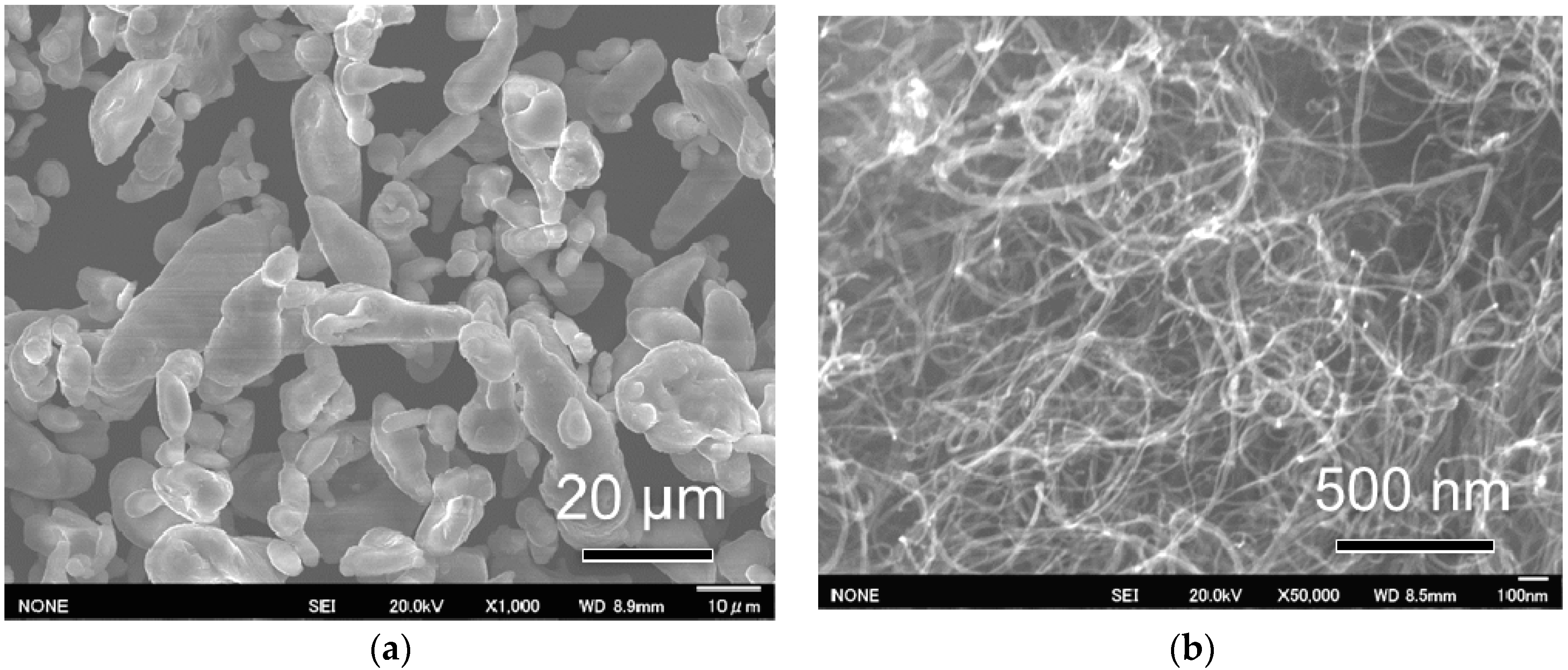
Figure 1 shows the morphologies of the starting Al and CNT powders. Starting Al powders have a near-spherical shape with an average diameter of ~20 μm (
Figure 1a). The starting CNTs are agglomerated under the strong Van der Waals force (
Figure 1b). CNTs have a slender shape with a large aspect ratio (~15 nm in diameter and ~1 μm in length). Large aspect ratios are favorable to achieve high load transfer efficiency of CNTs in composites [
5].
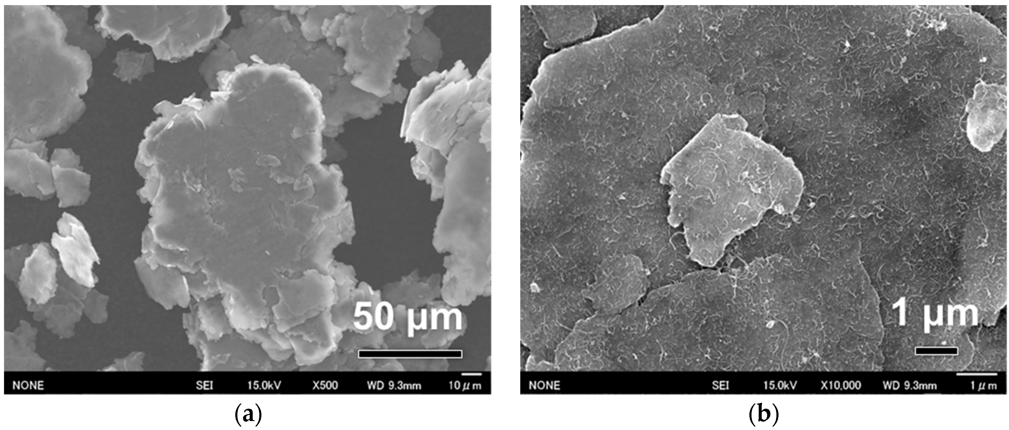
Figure 2 shows the morphology of fabricated flaky Al powder surface coated with 1 wt % CNTs. After ball milling for 240 min, Al powders changed from near-spherical (
Figure 1a) to flaky morphology with a thickness of several microns (
Figure 2a). Some small flakes were cold-welded to a large one with a thickness of several tens of microns. Formation of flaky powders were attributed to the good plastic deformability and the assistant effect of stearic acid. The flattening and welding of Al powders were common phenomena observed in the high-energy ball milling process [
8,
13]. A very uniform CNT dispersion was observed at a high-magnification view on the powder surface (
Figure 2b). The CNTs were homogeneously and randomly distributed on the flattened surface. The overlaps between CNTs were limited, suggesting a high dispersion quality. Compared with the previous solution coating process [
21], improved CNT dispersion was achieved in the present process due to the dynamic blending-assisted dispersion of CNTs [
10].
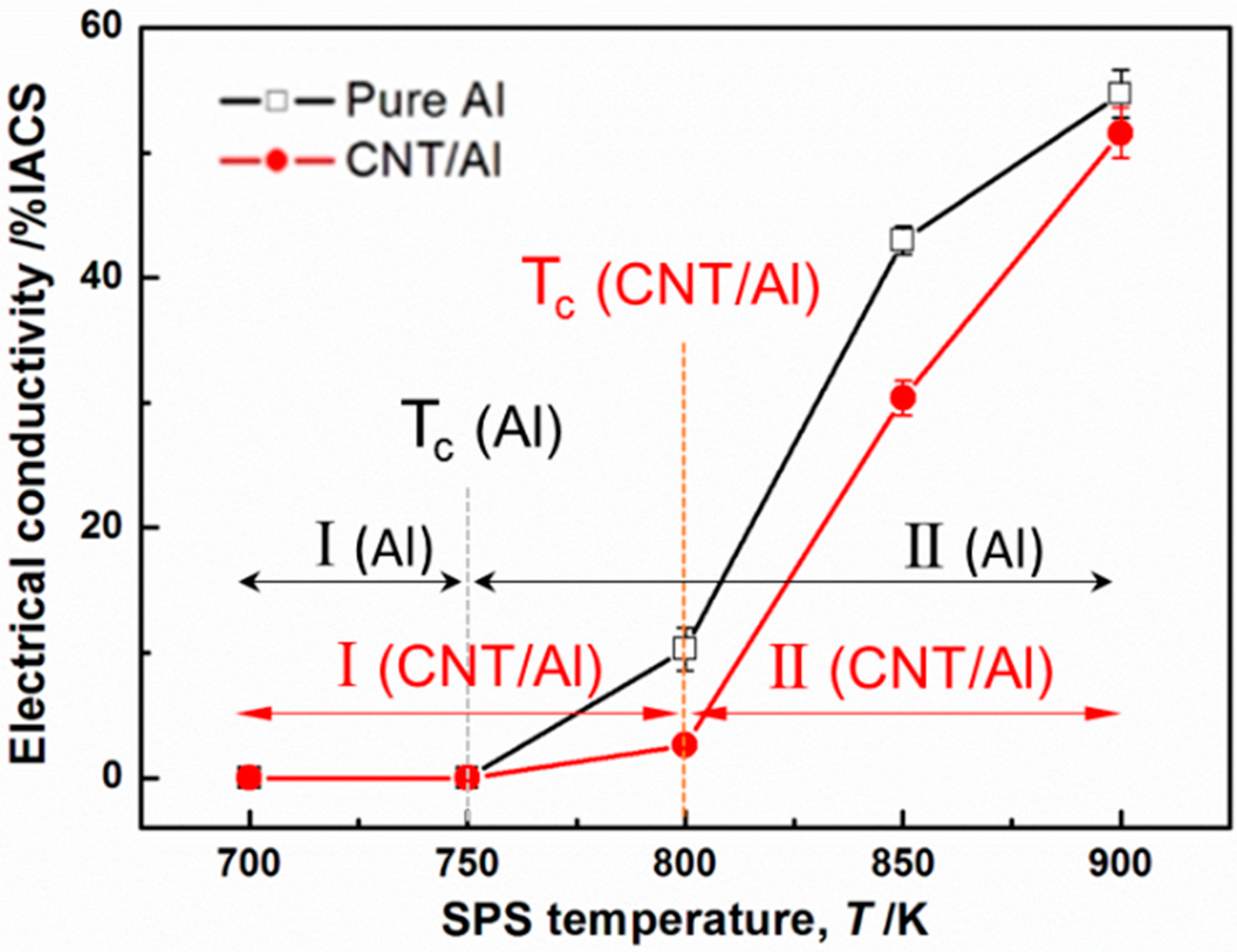
Figure 3 shows the measured electrical conductivity of the as-sintered pure Al and CNT–Al composites. It can be seen that the conductivity-temperature curves of both pure Al and CNT–Al composites exhibited two stages, divided by a critical temperature (
Tc) where the tendency transformed. At Stage I below
Tc, the conductivities were quite low, nearly zero. At Stage II beyond
Tc, the electrical conductivities dramatically improved with increasing temperature.
Tc was 750 K for pure Al, and it was 800 K for CNT–Al composites, suggesting a ~50 K increase of
Tc by adding CNTs in the Al matrix.
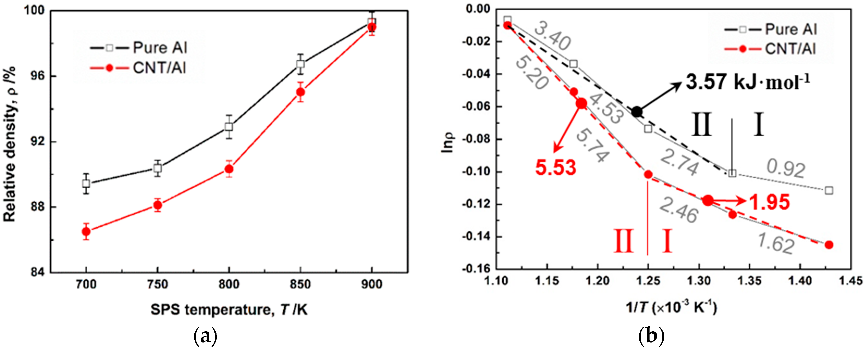
The densification analyses of pure Al and CNT–Al composite powders are shown in
Figure 4. With increasing SPS temperature, the relative density (ρ) of pure Al and CNT–Al composites increased continuously. Under each temperature, ρ of CNT–Al composites was smaller than that of pure Al. However, the difference became smaller at high temperatures. Even at 900 K, pure Al and CNT–Al composite showed similar values of ~99%. To clarify the kinetics of densification, the Arrhenius law was applied to estimate the activation energy (
Ea) of sintering [
22]:
where ρ
0 is a constant value.
Ea can be estimated from the slop of the curve of lnρ-(1/
T).
Figure 4b shows the plotted curves. It was interesting to find the two materials also had two stages whose
Ea values were distinct. The two stages were coincident with those found in the conductivity-temperature curves (
Figure 3). After
Tc, Stage II had increased
Ea compared with that of Stage I. Moreover, it was observed that CNT–Al composites had larger activation energy values than pure Al at the two stages. For example, at Stage II,
Ea was 5.53 kJ·mol
−1 for CNT–Al and 3.57 kJ·mol
−1 for pure Al, showing a 55% increment from pure Al to the CNT–Al composite. This suggests that the sintering rate of pure Al powder significantly decreased when CNTs were added.
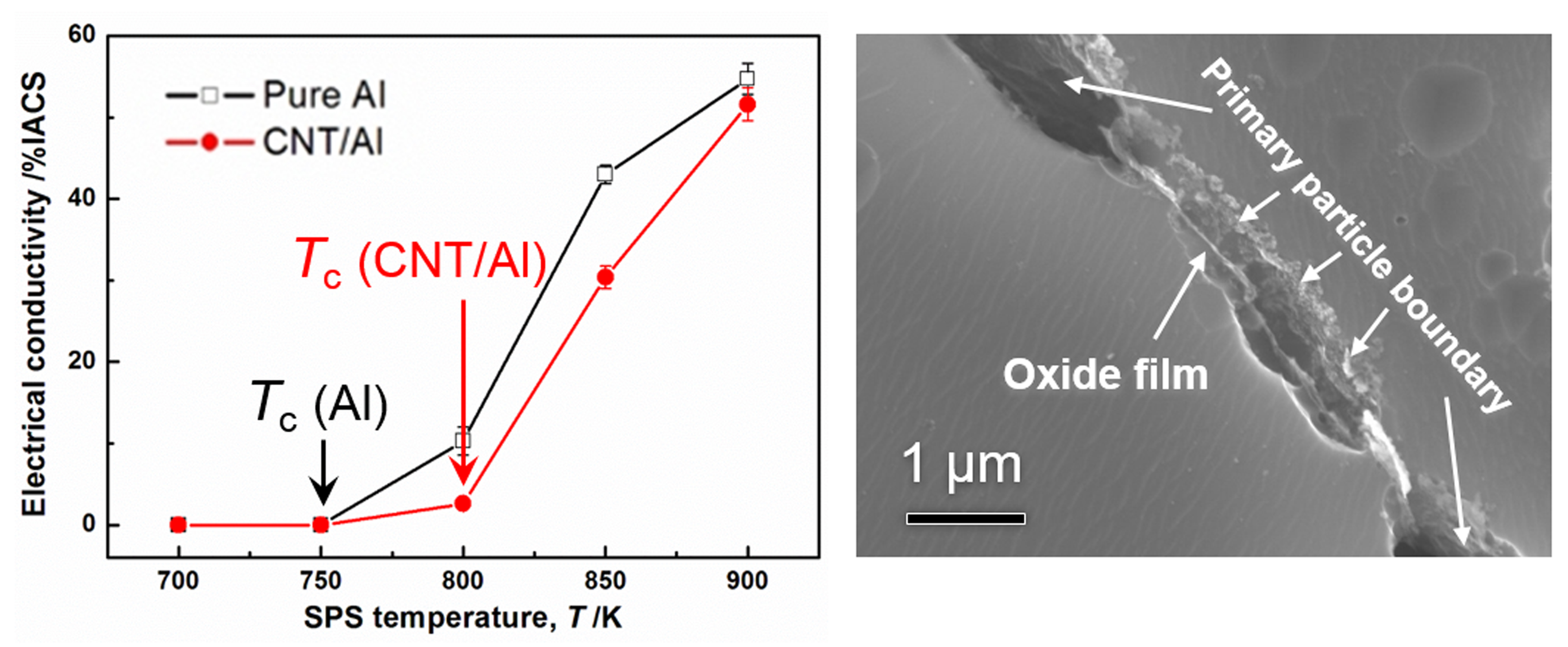
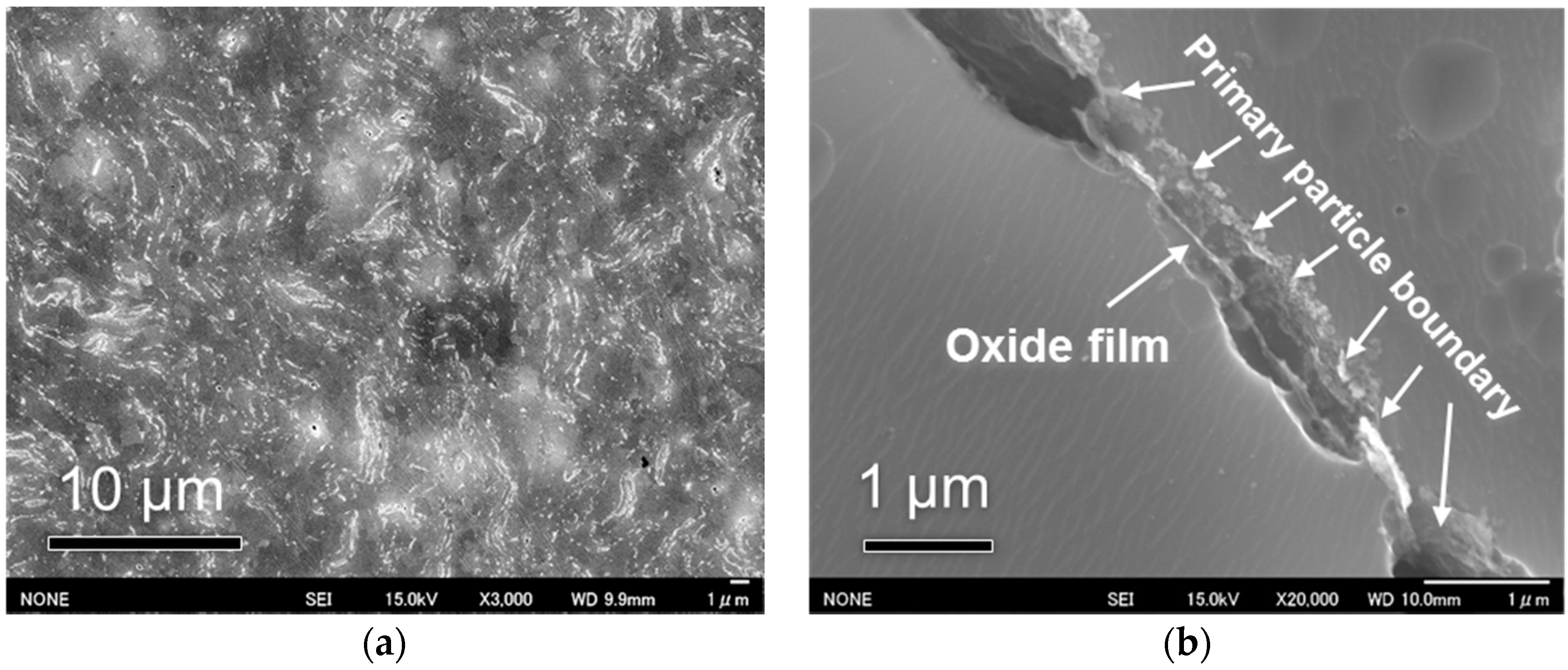
The polishing microstructure of CNT–Al composite sintered at 900 K is shown in
Figure 5. After chemical etching, the primary particle boundaries were revealed to show the boundaries between flaky Al powders, as observed in the white flow lines in
Figure 5a. From the high-magnification view on a primary particle boundary (
Figure 5b), a remained oxide film was observed which departed from the two powder particles.
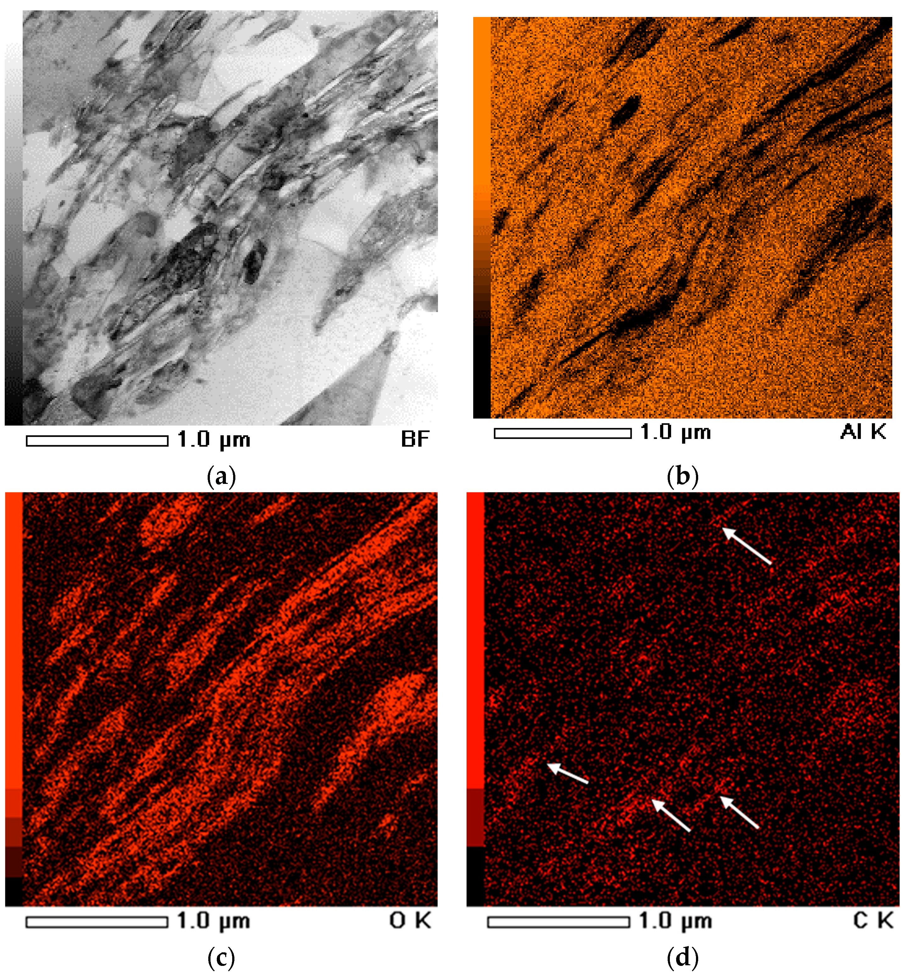
To confirm the oxide films, EDS-assisted TEM analysis was performed on CNT–Al sintered at 900 K, as shown in
Figure 6. Many discontinuous secondary phases were observe in the Al matrix (
Figure 6a). The phases had fibrous and disk-like shapes. From the EDS maps (
Figures 6b,c), these phases were less rich in Al and high concentrations of oxygen. Considering the low solubility of oxygen in Al, these phases can be identified as aluminum oxide or alumina, which has been commonly observed in powder metallurgy Al materials. Some carbon-concentrated areas were also observed from the carbon element distribution (as arrows indicated in
Figure 6d). It was corresponded to the CNT distribution in the Al matrix.
Acknowledgments
The authors would like to thank the support of TEM observations by Makoto Takahashi from JWRI, Osaka University, Japan.
Author Contributions
B.C. performed the experiments, analyzed the data, and wrote the paper. K.K. supervised the project.
Conflicts of Interest
The authors declare no conflict of interest.
References
- Iijima, S. Helical microtubules of graphitic carbon. Nature 1991, 354, 56–58. [Google Scholar] [CrossRef]
- Popov, V.N. Carbon nanotubes: Properties and application. Mater. Sci. Eng. R 2004, 43, 61–102. [Google Scholar] [CrossRef]
- Tjong, S.C. Recent progress in the development and properties of novel metal matrix nanocomposites reinforced with carbon nanotubes and graphene nanosheets. Mater. Sci. Eng. R 2013, 74, 281–350. [Google Scholar] [CrossRef]
- Esawi, A.M.; Farag, M.M. Carbon nanotube reinforced composites: Potential and current challenges. Mater. Des. 2007, 28, 2394–2401. [Google Scholar] [CrossRef]
- Chen, B.; Li, S.; Imai, H.; Jia, L.; Umeda, J.; Takahashi, M.; Kondoh, K. Load transfer strengthening in carbon nanotubes reinforced metal matrix composites via in situ tensile tests. Compos. Sci. Technol. 2015, 113, 1–8. [Google Scholar] [CrossRef]
- Chen, B.; Li, S.; Imai, H.; Jia, L.; Umeda, J.; Takahashi, M.; Kondoh, K. Carbon nanotube induced microstructural characteristics in powder metallurgy Al matrix composites and their effects on mechanical and conductive properties. J. Alloy. Compd. 2015, 651, 608–615. [Google Scholar] [CrossRef]
- He, C.; Zhao, N.; Shi, C.; Du, X.; Li, J.; Li, H.; Cui, Q. An Approach to Obtaining Homogeneously Dispersed Carbon Nanotubes in Al Powders for Preparing Reinforced Al-Matrix Composites. Adv. Mater. 2007, 19, 1128–1132. [Google Scholar] [CrossRef]
- Jiang, L.; Fan, G.; Li, Z.; Kai, X.; Zhang, D.; Chen, Z.; Humphries, S.; Heness, G.; Yeung, W.Y. An approach to the uniform dispersion of a high volume fraction of carbon nanotubes in aluminum powder. Carbon 2011, 49, 1965–1971. [Google Scholar] [CrossRef]
- Liu, Z.Y.; Xiao, B.L.; Wang, W.G.; Ma, Z.Y. Singly dispersed carbon nanotube/aluminum composites fabricated by powder metallurgy combined with friction stir processing. Carbon 2012, 50, 1843–1852. [Google Scholar] [CrossRef]
- Chen, B.; Li, S.; Imai, H.; Jia, L.; Umeda, J.; Takahashi, M.; Kondoh, K. An approach for homogeneous carbon nanotube dispersion in Al matrix composites. Mater. Des. 2015, 72, 1–8. [Google Scholar] [CrossRef]
- Uozumi, H.; Kobayashi, K.; Nakanishi, K.; Matsunaga, T.; Shinozaki, K.; Sakamoto, H.; Tsukada, T.; Masuda, C.; Yoshida, M. Fabrication process of carbon nanotube/light metal matrix composites by squeeze casting. Mater. Sci. Eng. A 2008, 495, 282–287. [Google Scholar] [CrossRef]
- Shin, S.E.; Bae, D.H. Strengthening behavior of chopped multi-walled carbon nanotube reinforced aluminum matrix composites. Mater. Charact. 2013, 83, 170–177. [Google Scholar] [CrossRef]
- Esawi, A.M.K.; Morsi, K.; Sayed, A.; Gawad, A.A.; Borah, P. Fabrication and properties of dispersed carbon nanotube-aluminum composites. Mater. Sci. Eng. A 2009, 508, 167–173. [Google Scholar] [CrossRef]
- Poirier, D.; Gauvin, R.; Drew, R.A.L. Structural characterization of a mechanically milled carbon nanotube/aluminum mixture. Compos. Part A Appl. Sci. Manuf. 2009, 40, 1482–1489. [Google Scholar] [CrossRef]
- Stein, J.; Lenczowski, B.; Anglaret, E.; Fréty, N. Influence of the concentration and nature of carbon nanotubes on the mechanical properties of AA5083 aluminium alloy matrix composites. Carbon 2014, 77, 44–52. [Google Scholar] [CrossRef]
- Saheb, N.; Iqbal, Z.; Khalil, A.; Hakeem, A.S.; Aqeeli, N.A.; Laoui, T.; Al-Qutub, A.; Kirchner, R. Spark plasma sintering of metals and metal matrix nanocomposites: A review. J. Nanomater. 2012, 2012, 18. [Google Scholar] [CrossRef]
- Chen, B.; Jia, L.; Li, S.; Imai, H.; Takahashi, M.; Kondoh, K. In Situ Synthesized Al4C3 Nanorods with Excellent Strengthening Effect in Aluminum Matrix Composites. Adv. Eng. Mater. 2014, 16, 972–975. [Google Scholar] [CrossRef]
- Zhan, G.-D.; Kuntz, J.; Wan, J.; Garay, J.; Mukherjee, A.K. Alumina-based nanocomposites consolidated by spark plasma sintering. Scr. Mater. 2002, 47, 737–741. [Google Scholar] [CrossRef]
- Kwon, H.; Estili, M.; Takagi, K.; Miyazaki, T.; Kawasaki, A. Combination of hot extrusion and spark plasma sintering for producing carbon nanotube reinforced aluminum matrix composites. Carbon 2009, 47, 570–577. [Google Scholar] [CrossRef]
- Chen, B.; Kondoh, K.; Imai, H.; Umeda, J.; Takahashi, M. Simultaneously enhancing strength and ductility of carbon nanotube/aluminum composites by improving bonding conditions. Scr. Mater. 2016, 113, 158–162. [Google Scholar] [CrossRef]
- Kondoh, K.; Fukuda, H.; Umeda, J.; Imai, H.; Fugetsu, B. Microstructural and mechanical behavior of multi-walled carbon nanotubes reinforced Al-Mg-Si alloy composites in aging treatment. Carbon 2014, 72, 15–21. [Google Scholar] [CrossRef]
- Aquilanti, V.; Mundim, K.C.; Elango, M.; Kleijn, S.; Kasai, T. Temperature dependence of chemical and biophysical rate processes: Phenomenological approach to deviations from Arrhenius law. Chem. Phys. Lett. 2010, 498, 209–213. [Google Scholar] [CrossRef]
© 2016 by the authors; licensee MDPI, Basel, Switzerland. This article is an open access article distributed under the terms and conditions of the Creative Commons Attribution (CC-BY) license (http://creativecommons.org/licenses/by/4.0/).


