
Specific Yielding of Selective Laser-Melted Ti6Al4V Open-Porous Scaffolds as a Function of Unit Cell Design and Dimensions

Abstract
:
1. Introduction
2. Materials and Methods
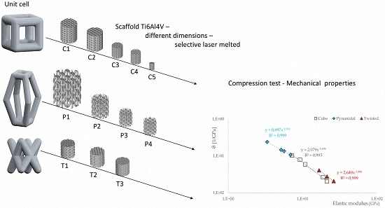
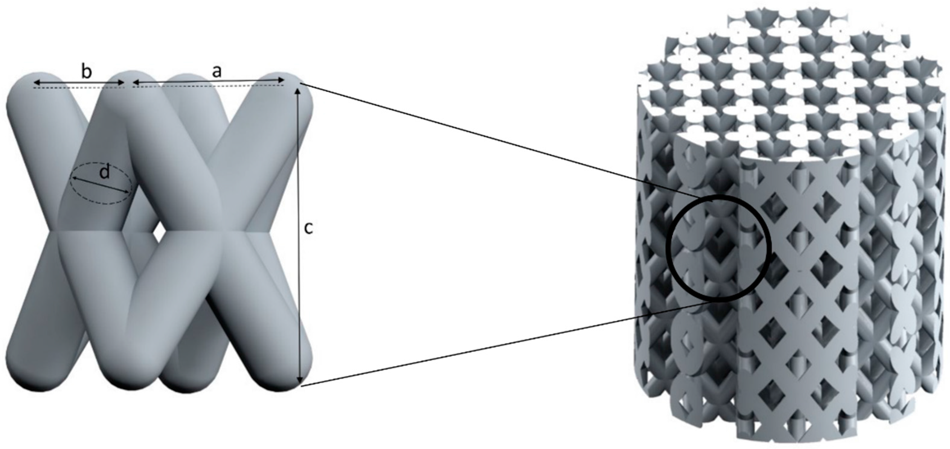
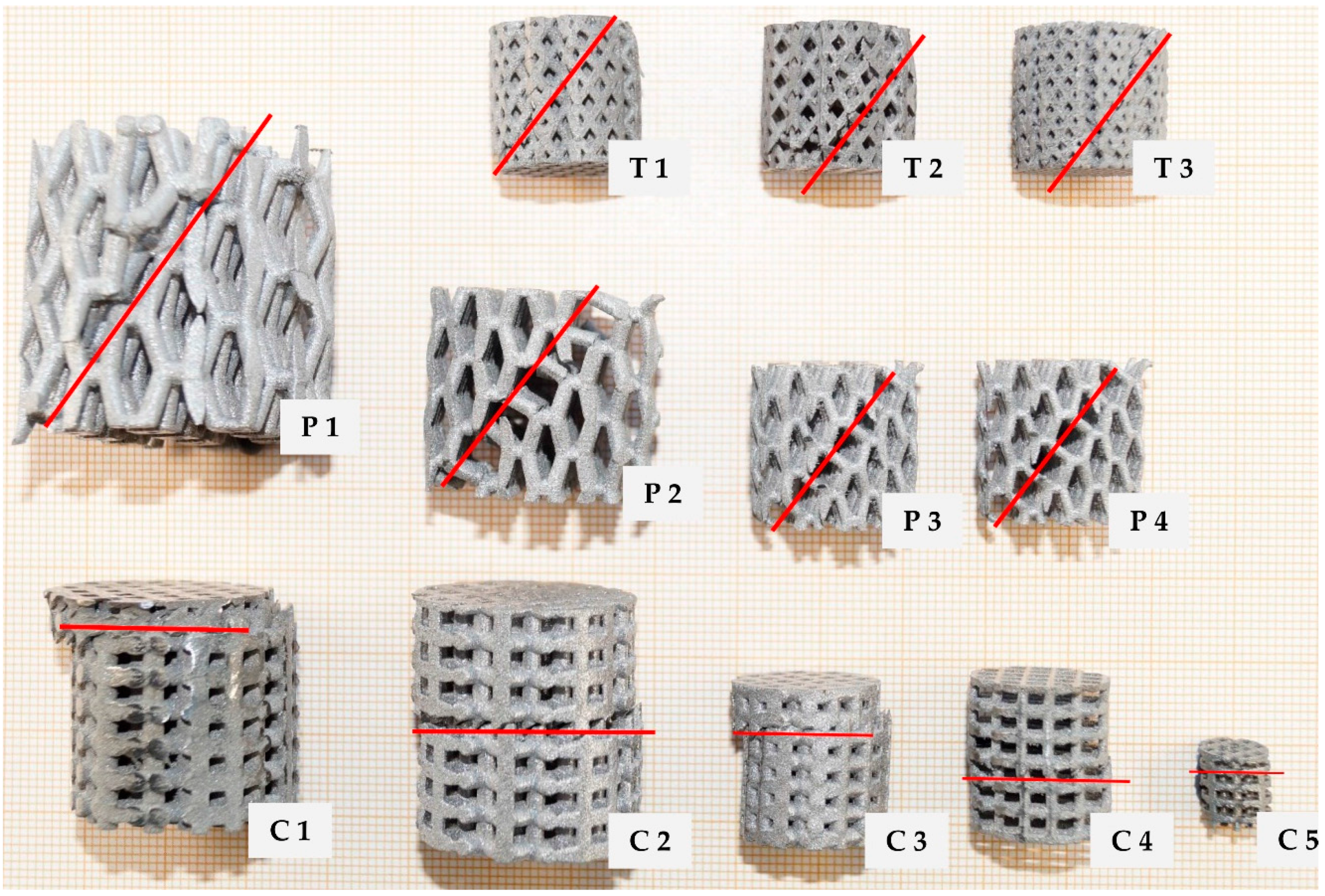
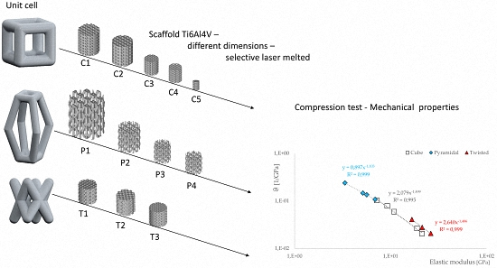
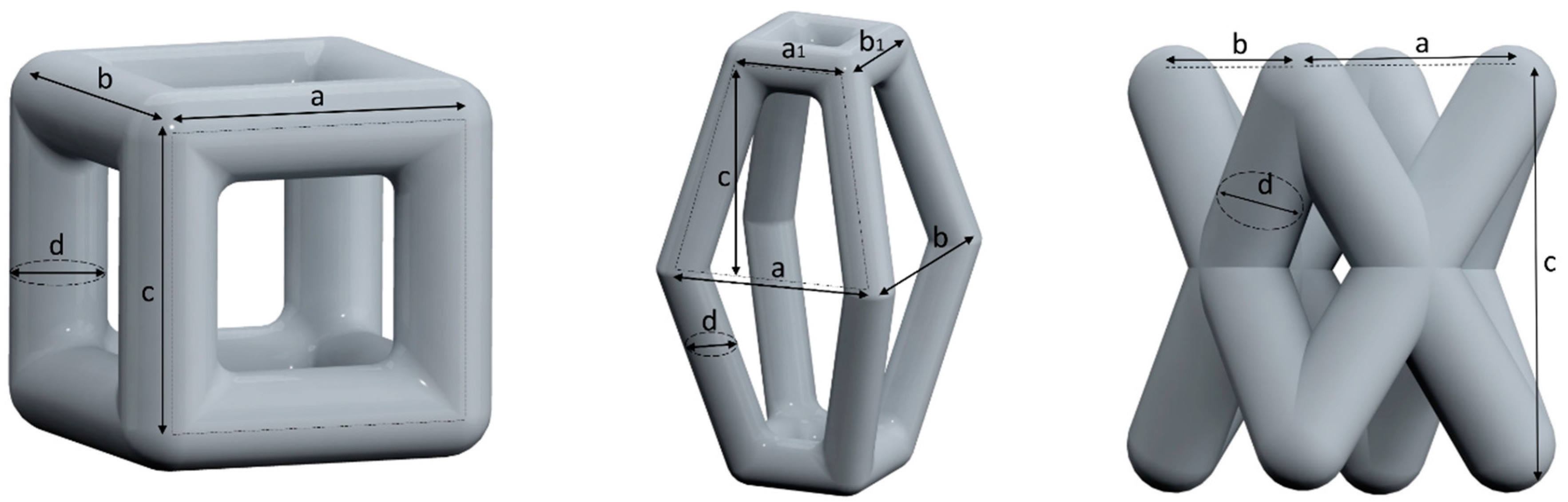
2.1. Unit Cell Designs and Configuration
- a cubic design (C),
- a truncated pyramidal design (P), and
- a twisted design with crossing struts (T).
2.2. Fabrication of the Scaffolds via an SLM Process
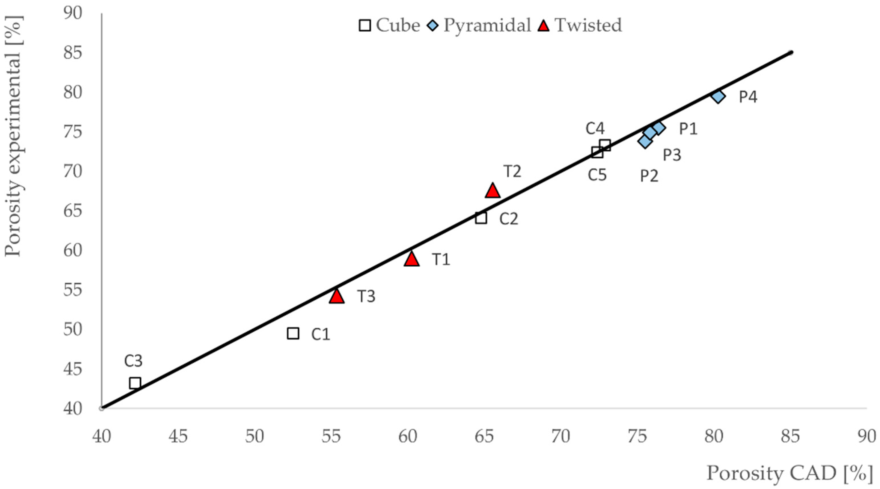
2.3. Calculating the Scaffold Porosity
2.4. Determination of the Mechanical Properties with Compression Testing
3. Results
3.1. Porosities of the Scaffolds
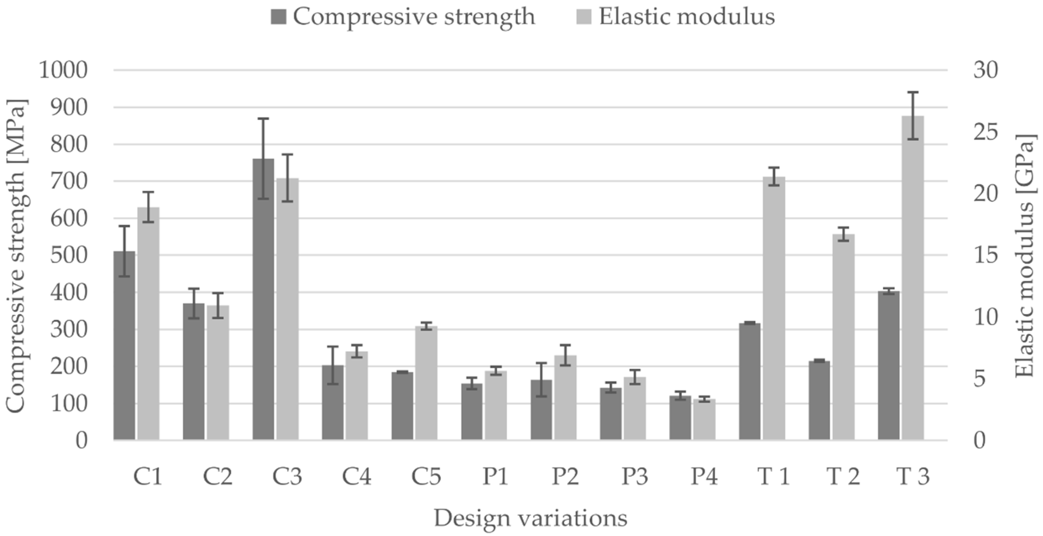
3.2. Compressive Modulus, Strength and Strain of the Scaffolds
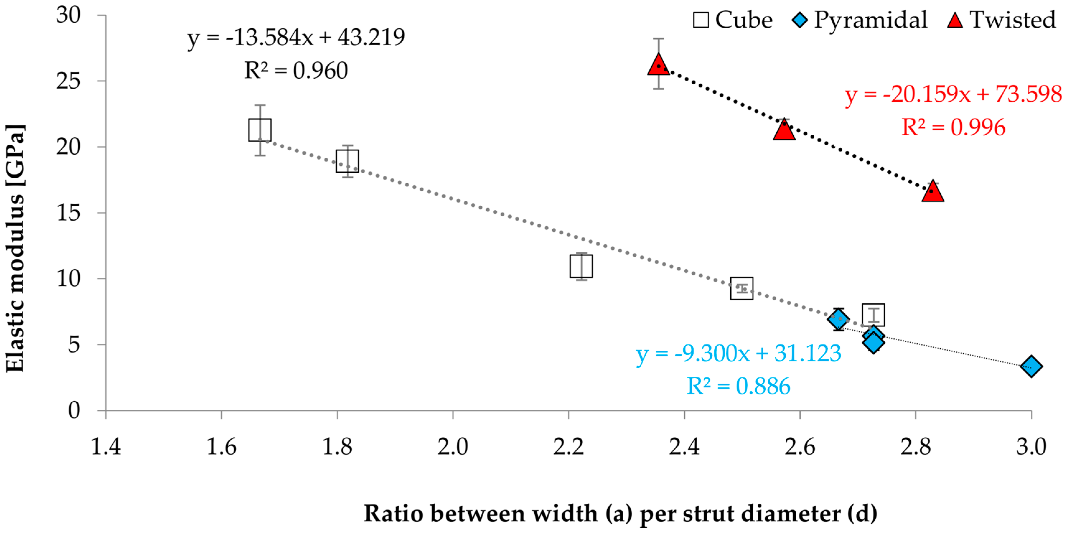
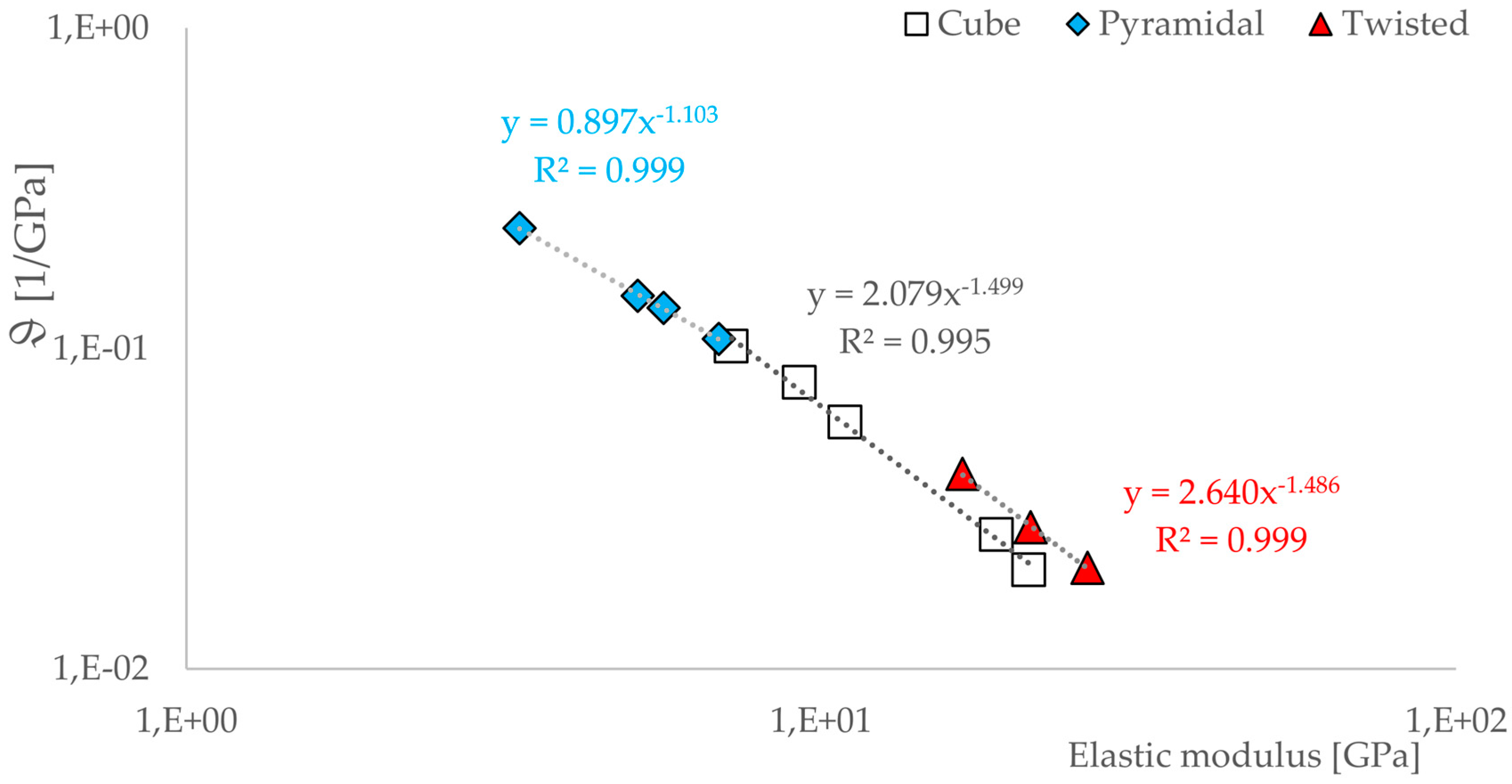
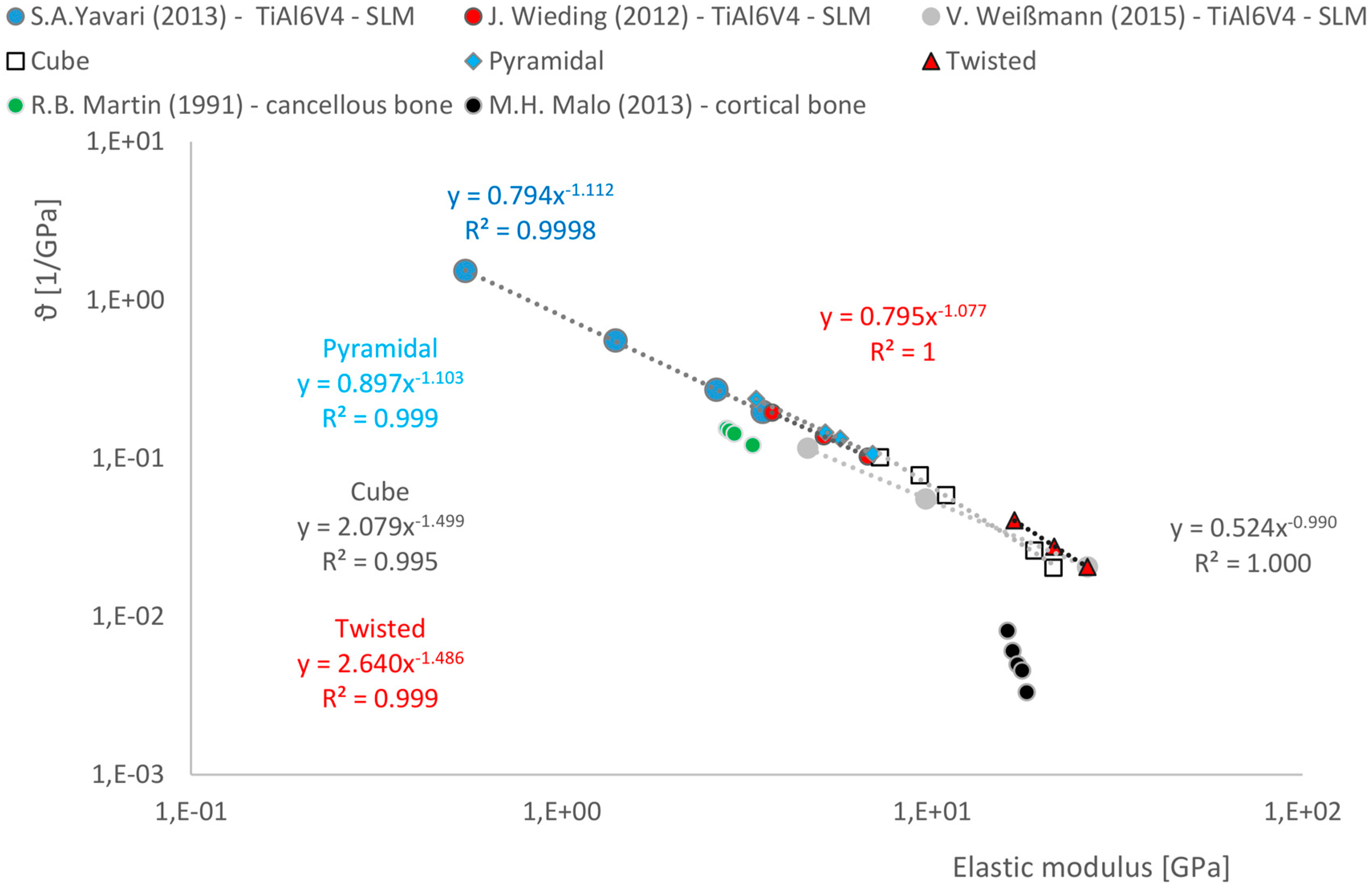
3.3. Correlations between Geometrical and Mechanical Properties
4. Discussion
5. Conclusions
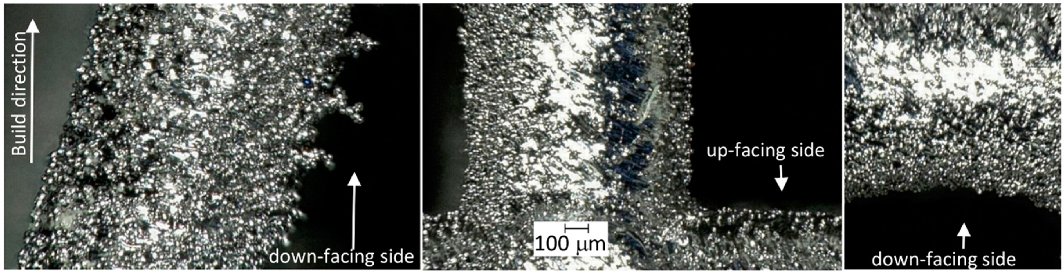
- In our work, we could demonstrate the possibility of fabricating different scaffold structures made of Ti6Al4V with high geometrical accuracy by using the SLM process. Porosity of the fabricated scaffolds differed less than 3.2% from the idealized porosity of the scaffolds as calculated by CAD.
- Based on tests under uniaxial loading conditions, the influence of unit cell dimension and of porosity on the mechanical properties was demonstrated.
- The size variation in unit cell dimension results in a change of their mechanical properties, this can be attributed to
- ○
- the geometric conditions of the unit cell, in particular the length ratio;
- ○
- the position of the struts towards the affected force
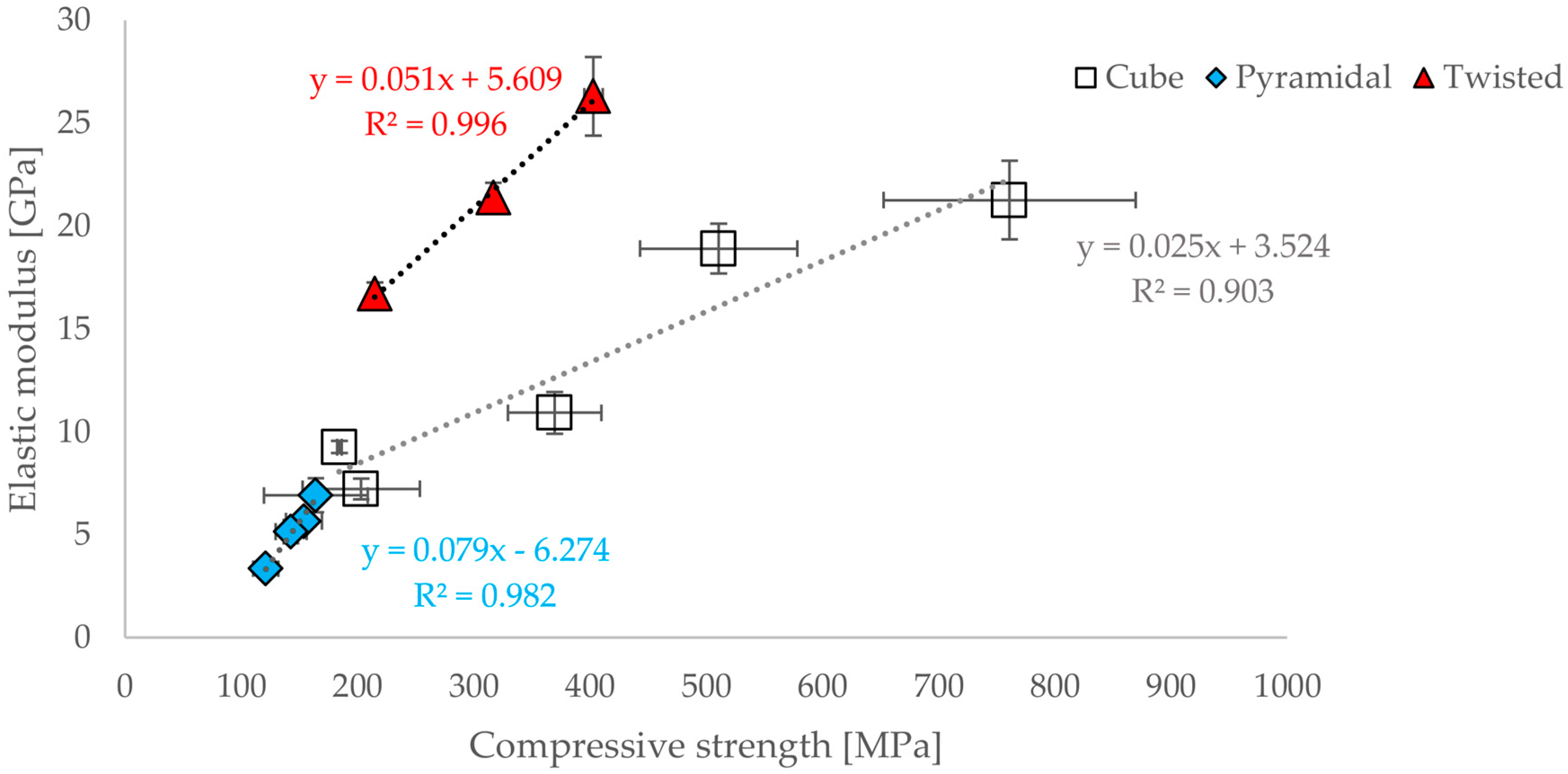
- A functional correlation between elastic modulus and compressive strain or compressive strength for all three geometric designs could be established.
- Nevertheless, a functional correlation with regard to the ratio of width of unit structure (a) and strut diameter (d) could be established.
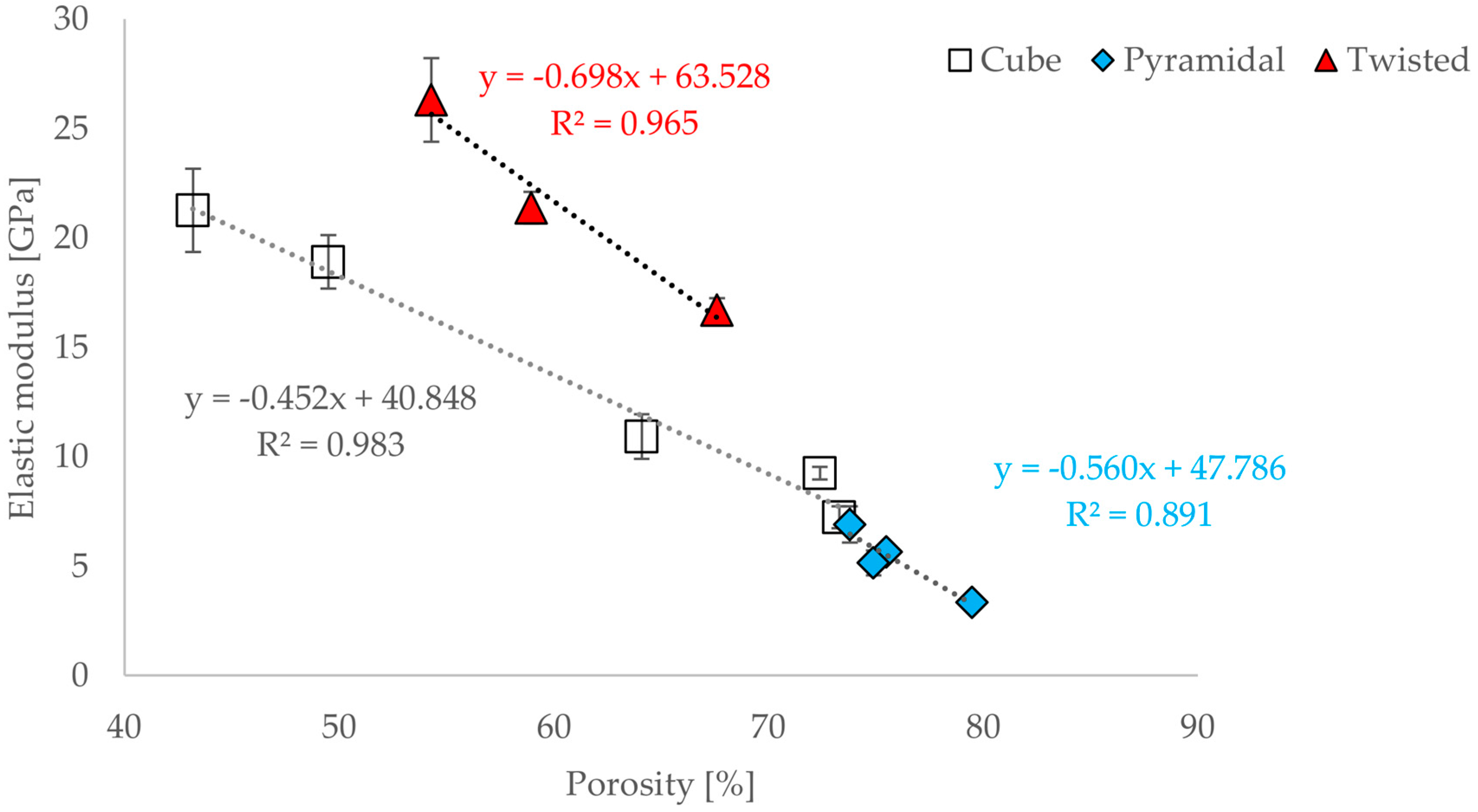
- There is a relationship between the porosity and the elastic modulus of open-porous structures. This relationship is valid for all tested structures and describable with the power law (5). The relationship is consistent with that found in other open-cell structures fabricated from Ti6AL4V by SLM. A direct comparison with human bone is possible. Since specific yielding is directly related to the volume of structures, it is possible to selectively decide which geometries, i.e., which structures are to be preferred.
- All scaffolds were strong enough to bear the impacting loads and achieved an elastic modulus within the specified range of human cortical bone depending on the geometrical parameter variations.
Acknowledgments
Author Contributions
Conflicts of Interest
References
- Vannoort, R. Titanium—The Implant Material of Today. J. Mater. Sci. 1987, 22, 3801–3811. [Google Scholar] [CrossRef]
- Wirtz, D.C.; Bader, C.; Reichel, H. Revisionsendoprothetik der Hüftpfanne; Springer Medizin Verlag: Heidelberg, Germany, 2008. [Google Scholar]
- Long, M.; Rack, H.J. Titanium alloys in total joint replacement—A material science perspective. Biomaterials 1998, 19, 1621–1639. [Google Scholar] [CrossRef]
- Öhmann, C.; Baleani, M.; Pani, C.; Taddei, F.; Alberghini, M.; Viceconti, M.; Manfrini, M. Compressive behaviour of child and adult cortical bone. Bone 2011, 49, 2011. [Google Scholar] [CrossRef] [PubMed]
- Bahraminasab, M.; Sahari, B.B.; Edwards, K.L.; Frahmand, F.; Arumugam, M. Aseptic loosening of femoral components—Materials engineering and design considerations. Mater. Des. 2013, 44, 155–163. [Google Scholar] [CrossRef]
- Tigges, S.; Stiles, R.G.; Roberson, J.R. Complications of Hip-Arthroplasty Causing Periprosthetic Radiolucency on Plain Radiographs. Am. J. Roentgenol. 1994, 162, 1387–1391. [Google Scholar] [CrossRef] [PubMed]
- Merle, C.; Streit, M.R.; Volz, C.; Pritsch, M.; Gotterbarm, T.; Aldinger, P.R. Bone remodeling around stable uncemented titanium stems during the second decade after total hip arthroplasty: A DXA study at 12 and 17 years. Osteoporos. Int. 2011, 22, 2879–2886. [Google Scholar] [CrossRef] [PubMed]
- Niinomi, M.; Nakai, M. Titanium-Based Biomaterials for Preventing Stress Shielding between Implant Devices and Bone. Int. J. Biomater. 2011. [Google Scholar] [CrossRef] [PubMed]
- Harrysson, O.L.; Cansizoglu, O.; Marcellin-Little, D.J.; Cormier, D.R.; West, H.A. Direct metal fabrication of titanium implants with tailored materials and mechanical properties using electron beam melting technology. Mater. Sci. Eng. C Biomim. Supramol. Syst. 2008, 28, 366–373. [Google Scholar] [CrossRef]
- Murr, L.E.; Gaytan, S.M.; Medina, F.; Lopez, H.; Martinez, E.; Machado, B.I.; Hernandez, D.H.; Martinez, L.; Lopez, M.I.; Wicker, R.B.; et al. Next-generation biomedical implants using additive manufacturing of complex, cellular and functional mesh arrays. Philos. Trans. R. Soc. A 2010, 368, 1999–2032. [Google Scholar] [CrossRef] [PubMed]
- Khanoki, S.A.; Pasini, D. Fatigue design of a mechanically biocompatible lattice for a proof-of-concept femoral stem. J. Mech. Behave. Biomed. Mater. 2013, 22, 65–83. [Google Scholar] [CrossRef] [PubMed]
- Bougherara, H.; Bureau, M.N.; Ya, L. Bone remodeling in a new biomimetic polymer-composite hip stem. J. Biomed. Mater. Res. Part A 2009, 92, 164–174. [Google Scholar] [CrossRef] [PubMed]
- Huiskes, R.; Weinans, H.; van Rietbergen, B. The relationship between stress shielding and bone resoprtion around hip stem and the effects of flexible materials. Clin. Orthop. Relat. Res. 1992, 274, 124–134. [Google Scholar] [PubMed]
- Yan, W.; Berthe, J.; Wenc, C. Numerical investigation of the effect of porous titanium femoral prosthesis on bone remodelling. Mater. Des. 2011, 32, 1776–1782. [Google Scholar] [CrossRef]
- Imwinkelried, T. Mechanical properties of open-porous titanium foam. J. Biomed. Mater. Res. A 2007, 81, 964–970. [Google Scholar] [CrossRef] [PubMed]
- Li, J.P.; Wijn, J.R.; van Blitterswijk, C.A.; de Groot, K. Comparison of porous Ti6Al4V made by sponge replication and directly 3D fiber deposition and cancellous bone. Key Eng. Mater. 2007, 330–332, 999–1002. [Google Scholar] [CrossRef]
- Mueller, U.; Imwinkelried, T.; Horst, M.; Sievers, M.; Graf-Hausner, U. Do human osteoblasts grow into open-porous titanium? Eur. Cell Mater. 2006, 11, 8–15. [Google Scholar]
- Cachinho, S.C.; Correia, R.N. Titanium scaffolds for osteointegration: Mechanical, in vitro and corrosion behaviour. J. Mater. Sci. Mater. Med. 2008, 19, 451–457. [Google Scholar] [CrossRef] [PubMed]
- Challis, V.J.; Roberts, A.P.; Grotowski, J.F.; Zhang, L.C.; Sercombe, T.B. Prototypes for Bone Implant Scaffold Designed via Topolgy Optimation and Manufactured by Solid Freeform Fabrication. Adv. Eng. Mater. 2010, 12, 1106–1110. [Google Scholar] [CrossRef]
- Cheah, C.M.; Chua, C.K.; Leong, K.F.; Cheong, C.H.; Naing, M.W. Automatic algorithm for generating complex polyhedral scaffold strutures for tissue engineering. Tissue Eng. 2004, 10, 595–610. [Google Scholar] [CrossRef] [PubMed]
- Emmelmann, C.; Scheinemann, P.; Munsch, M.; Seyda, V. Laser additive manufacturing of modified implant surfaces with osseointegrate characteristics. Phys. Procedia 2011, 12, 375–384. [Google Scholar] [CrossRef]
- Hazlehurst, K.; Wang, C.J.; Stanford, M. Evaluation of the stiffness characteristics of square pore CoCrMo cellular structures manufactured using laser melting technology for potential orthopaedic applications. Mater. Des. 2013, 51, 949–955. [Google Scholar] [CrossRef]
- Li, S.J.; Xu, Q.S.; Wang, Z.; Hou, W.T.; Hao, Y.L.; Yang, R.; Murr, L.E. Influence of cell shape on mechanical properties of Ti-6Al-4V meshes fabricated by electron beam melting method. Acta Biomater. 2014, 10, 4537–4547. [Google Scholar] [CrossRef] [PubMed]
- Luxner, M.H.; Stampfl, J.; Pettermann, H.E. Finite element modeling concepts and linear analyses of 3D regular open cell structures. J. Mater. Sci. 2005, 40, 5859–5866. [Google Scholar] [CrossRef]
- Parthasarathy, J.; Starly, B.; Raman, S.; Christensen, A. Mechanical evaluation of porous titanium (Ti6Al4V) structures with electron beam melting (EBM). J. Mech. Behav. Biomed. Mater. 2010, 3, 249–259. [Google Scholar] [CrossRef] [PubMed]
- Ryan, G.E.; McGarry, P.; Pandit, A.; Apatsidis, D. Analysis of the Mechanical Behavior of a Titanium Scaffold with a repeating unit-cell substructure. J. Biomed. Mater. Res. B Appl. Biomater. 2009, 90, 894–906. [Google Scholar] [CrossRef] [PubMed]
- Schwerdtfeger, J.; Heinl, P.; Singer, R.F.; Koerner, C. Auxetic cellular structures through selective electron-beam melting. Phys. Status Solid B Basic Solid State Phys. 2010, 247, 269–272. [Google Scholar] [CrossRef]
- Grimal, Q. Assessment of cortical bone elasticity and strength: Mechanical testing and ultrasound provide complementary data. Med. Eng. Phys. 2009, 31, 1140–1147. [Google Scholar] [CrossRef] [PubMed]
- Lewis, G. Properties of open-cell porous metals and alloys for orthopaedic applications. J. Mater. Sci. Mater. Med. 2013, 24, 2293–2325. [Google Scholar] [CrossRef] [PubMed]
- Jonitz-Heincke, A.; Wieding, J.; Schulze, C.; Hansmann, D.; Bader, R. Comparative analysis of the oxygen supply and viability of human osteoblasts in three-dimensional titanium scaffolds produced by laser-beam or electron beam melting. Materials 2013, 6, 5398–5409. [Google Scholar] [CrossRef]
- Wieding, J.; Wolf, A.; Bader, R. Numerical optimization of open-porous bone scaffold structures to match the elastic properties of human cortical bone. J. Mech. Behav. Biomed. Mater. 2014, 37, 56–68. [Google Scholar] [CrossRef] [PubMed]
- Wieding, J.; Jonitz, A.; Bader, R. The Effect of Structural Design on Mechanical Properties and Cellular Response of Additive Manufactured Titanium Scaffolds. Materials 2012, 5, 1336–1347. [Google Scholar] [CrossRef]
- Geetha, M.; Singh, A.K.; Asokamani, R.; Gogia, A.K. Ti based biomaterials, the ultimate choice for orthopaedic implants—A review. Prog. Mater. Sci. 2009, 54, 397–425. [Google Scholar] [CrossRef]
- Wauthle, R.; van der Stok, J.; Yavari, S.A.; van Humbeeck, J.; Kruth, J.P.; Zadpoor, A.A.; Weinans, H.; Mulier, M.; Schrooten, J. Additively manufactured porous tantalum implants. Acta Biomater. 2015, 14, 217–225. [Google Scholar] [CrossRef] [PubMed]
- Attar, H.; Löber, L.; Funk, A.; Calin, M.; Zhang, L.C.; Prashanth, K.G. Mechanical behavior of porous commercially pure Ti and Ti-TiB composite materials manufactured by selective laser melting. Mater. Sci. Eng. A 2015, 625, 350–356. [Google Scholar] [CrossRef]
- Wauthle, R.; Ahmadi, S.M.; Yavari, S.A.; Mulier, M.; Zadpoor, A.A.; Weinans, H.; van Humbeeck, J.; Kruth, J.P.; Schrooten, J. Revival of pure titanium for dynamically loaded porous implants using additive manufacturing. Mater. Sci. Eng. C 2015, 54, 94–100. [Google Scholar] [CrossRef] [PubMed]
- Rivera, S.; Panera, M.; Miranda, D.; Varela, F. Development of dense and cellular solids in CrCoMo alloy for orthopaedic applications. Procedia Eng. 2011, 10, 2979–2987. [Google Scholar] [CrossRef]
- Yavari, S.A.; Ahmadi, S.M.; Wauthle, R.; Pouran, B.; Schrooten, J.; Weinans, H.; Zadpoor, A.A. Relationship between unit cell type and porosity and the fatigue behavior of selective laser melted meta-biomaterials. J. Mech. Behav. Biomed. Mater. 2015, 43, 91–100. [Google Scholar] [CrossRef] [PubMed]
- Challis, V.J.; Xu, X.; Zhang, L.C.; Roberts, A.P.; Grotowski, J.F.; Sercombe, T.B. High specific strength and stiffness structures produced using selective laser melting. Mater. Des. 2014, 63, 783–788. [Google Scholar] [CrossRef]
- Marin, E.; Fusi, S.; Pressacco, M.; Paussa, L.; Fedrizzi, L. Characterization of cellular solids in Ti6Al4V for orthopaedic implant applications: Trabecular titanium. J. Mech. Behav. Biomed. Mater. 2010, 3, 373–381. [Google Scholar] [CrossRef] [PubMed]
- Markhoff, J.; Wieding, J.; Weißmann, V.; Pasold, J.; Jonitz-Heincke, A.; Bader, R. Influence of Different Three-Dimensional Open Porous Titanium Scaffold Designs on Human Osteoblasts Behavior in Static and Dynamic Cell Investigations. Materials 2015, 8, 5490–5507. [Google Scholar] [CrossRef]
- Song, B.; Dong, S.; Zhang, B.; Liao, H.; Coddet, C. Effects of processing parameters on microstructure and mechanical property. Mater. Des. 2012, 35, 120–125. [Google Scholar] [CrossRef]
- Attar, H.; Calin, M.; Zhang, L.C.; Scudino, S.; Eckert, J. Manufacture by selective laser melting and mechanical behavior of commercially pure titanium. Mater. Sci. Eng. A 2014, 593, 170–177. [Google Scholar] [CrossRef]
- Yadroitsev, I.; Krakhmalev, P.; Yadroitsava, I. Selective laser melting of Ti6Al4V alloy for biomedical applications temperature monitoring and microstructural evolution. J. Alloy. Compd. 2014, 583, 404–409. [Google Scholar] [CrossRef]
- Vrancken, B.; Thijs, L.; Kruth, J.P.; van Humbeeck, J. Heat treatment of Ti6Al4V produced by Selective Laser Melting: Microstructure and mechanical properties. J. Alloy. Compd. 2012, 541, 177–185. [Google Scholar] [CrossRef]
- Gibson, L.J.; Ashby, M.F.; Schajer, G.S.; Robertson, C.I. Mechanics of two-dimensional cellular materials. Proc. R. Soc. Lond. Ser. A Math. Phys. Sci. 1982. [Google Scholar] [CrossRef]
- Sanz-Herrera, J.A.; Doblare, M.; Garcia-Aznar, J.M. Scaffold microarchitecture determines internal bone directional growth structure: A numerical study. J. Biomech. 2010, 43, 2480–2486. [Google Scholar] [CrossRef] [PubMed]
- Campoli, G.; Borleffs, M.S.; Yavari, S.A.; Wauthle, R.; Weinans, H.; Zadpoor, A.A. Mechanical properties of open-cell metallic biomaterials manufactured using additive manufacturing. Mater. Des. 2013, 49, 957–965. [Google Scholar] [CrossRef]
- Heinl, P.; Müller, L.; Körner, C.; Singer, R.F.; Müller, F.A. Cellular Ti-6Al-4V structures with interconnected macro porosity. Acta Biomater. 2008, 4, 1536–1544. [Google Scholar] [CrossRef] [PubMed]
- Onck, P.R.; Andrews, E.W.; Gibson, L.J. Size effects in ductile cellular solids. Part I: Modeling. Int. J. Mech. Sci. 2001, 43, 681–699. [Google Scholar] [CrossRef]
- Andrews, E.W.; Gioux, G.; Onck, P.; Gibson, L.J. Size effects in ductile cellular solids. Part II: Experimental results. Int. J. Mech. Sci. 2001, 43, 701–713. [Google Scholar] [CrossRef]
- Bartolomeu, F.; Faria, S.; Carvalho, O.; Pinto, E.; Alves, N.; Silva, F.S.; Miranda, G. Predictive models for physical and mechanical properties of Ti6Al4V produced by selective laser melting. Mater. Sci. Eng. A 2016, 663, 181–192. [Google Scholar] [CrossRef]
- Weißmann, V.; Bader, R.; Hansmann, H.; Laufer, N. Influence of the structural orientation on the mechanical properties of selective laser melted Ti6Al4V open-porous scaffolds. Mater. Des. 2016, 95, 188–197. [Google Scholar] [CrossRef]
- Yavari, S.A.; Wauthle, R.; van der Stok, J.; Riemslag, A.C.; Janssen, A.C.; Mulier, M.; Kruth, J.P.; Schrooten, J.; Weinans, H.; Zadpoor, A.A. Fatigue behavior of porous biomaterials manufactured using selective laser melting. Mater. Sci. Eng. C 2013, 33, 4849–4858. [Google Scholar] [CrossRef] [PubMed]
- Jonitz-Heincke, A.; Wieding, J.; Schulze, C.; Hansmann, D.; Bader, R. Comparative Analysis of the Oxygen Supply and Viability of Human Osteoblasts in Three-Dimensional Titanium Scaffolds Produced by Laser-Beam or Electron-Beam Melting. Materials 2013, 6, 5398–5409. [Google Scholar] [CrossRef]
- Olivares, A.L.; Marsal, E.; Planell, J.A.; Lacroix, D. Finite element study of scaffold architecture design and culture conditions for tissue engineering. Biomaterials 2009, 30, 6142–6149. [Google Scholar] [CrossRef] [PubMed]
- Li, X.; Wang, C.T.; Zhang, W.G.; Li, Y.C. Fabrication and compressive properties of Ti6Al4V implant with honeycomb-like structure for biomedical applicatios. Rapid Prototyp. J. 2010, 16, 44–49. [Google Scholar] [CrossRef]
- Abele, E.; Stoffregen, H.A.; Kniepkamp, M.; Lang, S. Selective laser melting for manufacturing of thin-walled porous elements. J. Mater. Process. Technol. 2015, 215, 114–122. [Google Scholar] [CrossRef]
- Yadroitsev, I.; Smurov, I. Surface Morphology in Selective Laser Melting of Metal Powders. Phys. Procedia 2011, 12, 264–270. [Google Scholar] [CrossRef]
- Kasperovich, G.; Hausmann, J. Improvement of fatigue resistance and ductility of TiAl6V4 processed by selective laser melting. J. Mater. Process. Technol. 2015, 220, 202–214. [Google Scholar] [CrossRef]
- Suard, M.; Martin, G.; Lhuissier, P.; Dendievel, R.; Vignat, F.; Blandin, J.-J. Mechanical equivalent diameter of single struts for the stiffness prediction of lattice structures produced by electron beam melting. Addit. Manuf. 2015, 8, 124–131. [Google Scholar] [CrossRef]
- Zhang, S.; Wei, Q.; Cheng, L.; Li, S.; Shi, Y. Effects of scan line spacing on pore characteristics and mechanical properties of porous Ti6Al4V implants fabricated by selective laser melting. Mater. Des. 2014, 63, 185–193. [Google Scholar] [CrossRef]
- Wieding, J.; Souffrant, R.; Mittelmeier, W.; Bader, R. Finite element analysis on the biomechanical stability of open-porous titanium scaffolds for large segmental bone defects under physiological load conditions. Med. Eng. Phys. 2013, 35, 422–432. [Google Scholar] [CrossRef] [PubMed]
- Cheng, X.Y.; Li, S.J.; Murr, L.E.; Zhang, Z.B.; Hao, Y.L.; Yang, R.; Medina, F.; Wicker, R.B. Compression deformation behavior of Ti-6Al-4V alloy with cellular structures fabricated by electron beam melting. J. Mech. Behav. Biomed. Mater. 2012, 16, 153–162. [Google Scholar] [CrossRef] [PubMed]
- Xiao, L.; Song, W.; Wang, C.; Liu, H.; Tang, H.; Wang, J. Mechanical behavior of open-cell rhombic dodecahedron Ti-6Al-4V lattice structure. Mater. Sci. Eng. A 2015, 640, 375–384. [Google Scholar] [CrossRef]
- Kadkhodapour, J.; Montazerian, A.C.; Darabi, A.P.; Anaraki, A.P.; Ahmadi, S.M.; Zadpoor, A.A.; Schmauder, S. Failure mechanisms of additively manufactured porous biomaterials: Effects of porosity and type of unit cell. J. Mech. Behav. Biomed. Mater. 2015, 50, 180–191. [Google Scholar] [CrossRef] [PubMed]
- Malo, M.H.; Rohrbach, D.; Isaksson, H.; Töyräs, J.; Jurvelin, J.S.; Tamminen, I.S. Longitudinal elastic properties and porosity of cortical bone tissue vary with age in human proximal femur. Bone 2013, 53, 451–458. [Google Scholar] [CrossRef] [PubMed]
- Martin, R.B. Determinants of the mechanical properties of bones. J. Biomech. 1991, 24, 79–88. [Google Scholar] [CrossRef]


| Basic Design | Configu-Ration | Unit Structure | Scaffold Structure | ||||||
|---|---|---|---|---|---|---|---|---|---|
| Height (c) | Width (a) | Width (a1) | Depth (b) | Depth (b1) | Strut Diameter (d) | Height (H) | Diameter (D) | ||
| Cube | |||||||||
 | C1 | 4.0 | 4.0 | --- | 4.0 | --- | 2.2 | 30.1 | 26.1 |
| C2 | 4.0 | 4.0 | --- | 4.0 | --- | 1.8 | 29.1 | 25.6 | |
| C3 | 3.0 | 3.0 | --- | 3.0 | --- | 1.8 | 20.2 | 16.8 | |
| C4 | 3.0 | 3.0 | --- | 3.0 | --- | 1.1 | 19.1 | 16.1 | |
| C5 | 2.0 | 2.0 | --- | 2.0 | --- | 0.8 | 10.6 | 8.1 | |
| Truncated Pyramid | |||||||||
 | P1 | 6.0 | 6.0 | 3.0 | 6.0 | 3.0 | 2.2 | 37.2 | 35.2 |
| P2 | 4.0 | 4.0 | 2.0 | 4.0 | 2.0 | 1.5 | 25.4 | 23.2 | |
| P3 | 3.0 | 3.0 | 1.5 | 3.0 | 1.5 | 1.1 | 19.6 | 17.6 | |
| P4 | 3.0 | 3.0 | 1.5 | 3.0 | 1.5 | 1.0 | 19.7 | 17.6 | |
| Twisted | |||||||||
 | T1 | 4.0 | 2.83 | --- | 2.83 | --- | 1.1 | 18.0 | 17.0 |
| T2 | 4.0 | 2.83 | --- | 2.83 | --- | 1.0 | 18.0 | 17.0 | |
| T3 | 3.0 | 2.12 | --- | 2.12 | --- | 0.9 | 18.0 | 17.0 | |
| Design | Elastic Modulus (GPa) | Compressive Strength (MPa) | Compressive Strain (%) |
|---|---|---|---|
| C1 | 18.9 ± 1.2 | 510.7 ± 67.8 | 4.2 ± 2.6 |
| C2 | 10.9 ± 1.0 | 369.7 ± 40.3 | 4.0 ± 0.7 |
| C3 | 21.6 ± 1.9 | 761.1 ± 108.6 | 4.6 ± 1.3 |
| C4 | 7.2 ± 0.5 | 203.1 ± 50.4 | 2.7 ± 0.6 |
| C5 | 9.3 ± 0.3 | 184.4 ± 2.1 | 3.2 ± 0.3 |
| P1 | 5.7 ± 0.3 | 153.9 ± 15.5 | 3.0 ± 0.3 |
| P2 | 6.9 ± 0.8 | 164.1 ± 44.8 | 2.6 ± 0.7 |
| P3 | 5.2 ± 0.6 | 142.8 ± 13.3 | 2.8 ± 0.1 |
| P4 | 3.4 ± 0.2 | 121.1 ± 10.9 | 3.6 ± 0.2 |
| T1 | 21.4 ± 0.7 | 316.9 ± 2.3 | 2.8 ± 0.2 |
| T2 | 16.7 ± 0.6 | 215.0 ± 3.0 | 3.2 ± 0.2 |
| T3 | 26.3± 1.9 | 402.9 ± 7.9 | 4.1 ± 0.1 |
| Parameter | Description | Unit | Process Parameter |
|---|---|---|---|
| P | Laser Power | W | 275 |
| v | Scan speed | mm/s | 805 |
| d | Hatch spacing | µm | 120 |
| t | Layer thickness | µm | 30 |
© 2016 by the authors; licensee MDPI, Basel, Switzerland. This article is an open access article distributed under the terms and conditions of the Creative Commons Attribution (CC-BY) license (http://creativecommons.org/licenses/by/4.0/).
Share and Cite
Weißmann, V.; Wieding, J.; Hansmann, H.; Laufer, N.; Wolf, A.; Bader, R. Specific Yielding of Selective Laser-Melted Ti6Al4V Open-Porous Scaffolds as a Function of Unit Cell Design and Dimensions. Metals 2016, 6, 166. https://doi.org/10.3390/met6070166
Weißmann V, Wieding J, Hansmann H, Laufer N, Wolf A, Bader R. Specific Yielding of Selective Laser-Melted Ti6Al4V Open-Porous Scaffolds as a Function of Unit Cell Design and Dimensions. Metals. 2016; 6(7):166. https://doi.org/10.3390/met6070166
Chicago/Turabian StyleWeißmann, Volker, Jan Wieding, Harald Hansmann, Nico Laufer, Andreas Wolf, and Rainer Bader. 2016. "Specific Yielding of Selective Laser-Melted Ti6Al4V Open-Porous Scaffolds as a Function of Unit Cell Design and Dimensions" Metals 6, no. 7: 166. https://doi.org/10.3390/met6070166
APA StyleWeißmann, V., Wieding, J., Hansmann, H., Laufer, N., Wolf, A., & Bader, R. (2016). Specific Yielding of Selective Laser-Melted Ti6Al4V Open-Porous Scaffolds as a Function of Unit Cell Design and Dimensions. Metals, 6(7), 166. https://doi.org/10.3390/met6070166