Article

Effect of Welding Speed on Defect Features and Mechanical Performance of Friction Stir Lap Welded 7B04 Aluminum Alloy

State Key Laboratory of Robotics, Shenyang Institute of Automation, Chinese Academy of Sciences, Shenyang 110000, China
*
Author to whom correspondence should be addressed.
Metals 2016, 6(4), 87; https://doi.org/10.3390/met6040087
Submission received: 9 March 2016 / Revised: 6 April 2016 / Accepted: 11 April 2016 / Published: 15 April 2016
(This article belongs to the Special Issue Aluminum Alloys)

Abstract

:
Friction stir lap welding of 7B04 aluminum alloy was conducted in the present paper, and the effect of welding speed on the defect features and mechanical performance of lap joints was investigated. The results indicate that the hook defect at the advancing side (AS) can reduce the effective thickness of the top sheet, and the sheet thinning level is gradually lowered by increasing the welding speed. The cold lap defect at the retreating side (RS) can result in effective thickness reduction in both top and bottom sheets, and the total height of the cold lap defect varies slightly with the welding speed. The tensile properties of the lap joints are largely related to the sheet thinning levels caused by the defects. The fracture strength of AS-loaded lap joints is progressively increased with increasing welding speed, while that of RS-loaded lap joints evolves slightly with welding speed. It is found that the affecting characteristic of loading configuration on the joint performance is also dependent on the welding speed. At lower welding speeds, the AS-loaded lap joints show lower fracture strength than the RS-loaded lap joints. When the welding speed is high, the AS-loaded lap joints present superior tensile properties to RS-loaded lap joints.

Graphical Abstract

1. Introduction

Friction stir welding (FSW) has been extensively utilized to weld various aluminum alloys since its invention in 1991 [1,2,3]. The focuses of previous investigations on FSW were mainly placed on the butt joint configuration. In fact, the lap joint configuration is also widely used in joining aluminum alloy structures, particularly in automotive and aerospace industries. Thus, a number of studies have also been conducted on friction stir lap welding (FSLW) of aluminum alloys [3].
In FSLW, two welding samples are overlapped by a certain width. A rotating tool is plunged into the top sheet and traversed along the centerline of the overlap. After the tool removal, a lap linear weld is then produced. Compared with friction stir seam welding, FSLW defects, resulting from the movement of the initial faying surface during the tool stirring, are inevitably present on both advancing and retreating sides of the lap joints [4]. On the advancing side (AS), the faying surface of the lap joint generally remains outside the weld nugget and folds upwards along the nugget boundary, which is known as the hook defect. On the retreating side (RS), the faying surface first lifts up and then penetrates into the nugget, which is known as the cold lap defect. The hook and cold lap defects are actually reflections of material flow patterns at the faying surface of the lap joint, and thus their profiles are significantly influenced by the tool’s geometrical features and process parameters. For FSLW of aluminum alloys, developing specific shapes of tools and optimizing the process parameters would contribute to the minimization of defect levels in lap joints [5,6,7,8].
The hook and cold lap defects act to reduce the effective thickness of the lap joints, which exerts significant effect on their mechanical properties. The correlations between the hook defect at AS and joint performance have been extensively investigated. In Yadava et al.’s research [6], the load-carrying ability of lap joints was found to be linearly decreased with the increase of the height of the hook defect, indicating that the height of the hook defect had remarkable influence on the joint properties. A similar phenomenon was also observed in our previous study on FSLW of 7B04 aluminum alloy where the large height of the hook defect would lead to the poor tensile properties of the joints [9]. Nevertheless, Yazdanian et al. [7] suggested that for the FSLW of 3-mm-thick 6060-T5 aluminum alloy, the strength reduction due to the hook defect only became significant when the height of the hook defect reached a critical value of ~0.9 mm. Furthermore, the author pointed out that the hook defect was not the only factor affecting the joint properties. The local softening occurring in the heat affected zone could be another important factor determining the fracture location and the final fracture strength. Until now, the effect of the hook defect on properties of FSLW joints has been investigated in a large amount of papers, whereas only a few investigations are related to the correlation between the cold lap defect and the performance of lap joints.
Because of the different characteristic profiles of the hook and cold lap defects, the FSLW joints can be produced in two different loading configurations, which are AS loading and RS loading, respectively [10,11,12,13]. In AS loading, the AS of a lap joint is loaded on the upper plate, while in RS loading, the RS of a lap joint is loaded on the upper plate (see Figure 1). Several researchers have pointed out that different loading configurations could lead to different mechanical properties of lap joints for a given set of process parameters. In Cederqvist et al.’s research [4], the 2024-T3 and 7075-T6 aluminum alloys were friction stir lap welded, and the effect of loading configuration on joint properties was investigated. The results indicated that the initial faying surface on AS did not exhibit detectable uplift, and the AS-loaded lap joints showed higher strength than the RS-loaded lap joints. Buffa et al. [11] carried out the FSLW of AA2198-T4 aluminum alloy at three different heat input levels. It was found that the joints obtained in the AS loading configuration always showed definitively larger tensile properties than the ones welded in the RS loading configuration. The author argued that this was because the hook defects on AS did not negatively affect the transmitting load capability of the welded joints, but a deeper explanation was lacking. On the other hand, the phenomenon of higher fracture strength in RS loading compared with AS loading has been reported by other researchers [12,13]. The smaller extent of sheet thinning and lower stress concentration on the RS were considered to be the main reasons for the higher fracture strength of RS loading. Understanding the effect of loading configuration on joint performance is of great significance because it can assist in choosing the appropriate lap configuration for FSLW from the perspective of structure security design. However, this problem is not quite clear and is currently still controversial.
The above statements have shown that the hook and cold lap defects have negative effects on mechanical properties of lap joints; therefore, the defect size should be minimized by process optimization in order to improve the joint properties. Since the correlations between process parameters and joint performances are relatively complex, illuminating the affecting characteristics of process parameters on the defect features and mechanical performance of lap joints is of importance and significance, and this would provide guidance for process optimization.
The 7B04 aluminum alloy has high specific strength and good corrosion resistance, and has been widely utilized for lightweight structures in the aviation industry. In this study, a 7B04-T74 aluminum alloy is friction stir lap welded, and the effect of welding speed on the defect features and mechanical performance of the lap joints is investigated. The focuses are mainly placed on the evolutions of the defect features, the load-carrying ability of the lap joints and the affecting characteristics of the loading configuration on the joint properties with welding speed. The present study is expected to provide guidance for the optimization of the FSLW process and the security design of the lap structure.

2. Materials and Methods

A 7B04-T74 aluminum alloy with a thickness of 2 mm was used for both the top and bottom sheets of the lap joints, whose chemical compositions and mechanical properties are listed in Table 1. Both top and bottom sheets were 150 mm long and 100 mm wide. The longitudinal direction of the plates was perpendicular to the plate rolling direction.
After being cleaned by acetone, two welding samples were overlapped by a width of 50 mm along the longitudinal direction of the plates and tightly clamped on the work table by the welding fixture. FSLW was performed along the centerline of the overlap using a FSW machine. In the present study, FSLW experiments were conducted in both AS loading and RS loading configurations. The lap joints produced from both loading configurations were named as the AS-loaded lap joint and RS-loaded lap joint, respectively. The welding tool used for the experiments had a 12-mm-diameter shoulder and a conical right-hand screwed pin. The tool pin had a diameter of 4.5 mm (at the shoulder) and a pin length of 2.8 mm. Note that the pin length of the welding tool is the optimal result of our previous work [9]. During the welding, an axial load of 4.6 kN and a tilting angle of 2.5° were applied to the welding tool. The rotation speed was fixed at a constant value of 600 rpm and the welding speed varied from 50 to 200 mm/min.
After welding, the joints were cross-sectioned perpendicular to the welding direction for metallographic analysis and tensile testing. The cross-sections of the metallographic specimens were polished using a diamond paste, etched with Keller’s reagent and observed by an optical microscopy (KEYENCE VHX-100). The Vickers microhardness profiles were measured on the middle of the upper sheets throughout the cross-sections with a load of 500 g and a dwell time of 10 s. Weld strengths of the joints were evaluated by lap shear tests. Rectangular test specimens with the width of 15 mm were cut from friction stir lap welds perpendicular to the welding direction. During the test, samples were aligned by using 2-mm-thick 7B04-T74 aluminum spacers in the clamping grip in order to ensure that an initial pure shear load was applied to the interfacial plane. Lap shear testing was conducted at a rate of 1.0 mm/min. Three samples were tested for each combination of experimental parameters. The fracture strength of a sample, defined by dividing the fracture load by the sample width (N/mm), was utilized to determine the load-carrying ability of FSLW joints. This has been commonly used to evaluate the mechanical properties of a friction stir lap welded joint in previous studies [5,6,7,8]. After tensile test, the optical microscopy mentioned above was utilized to analyze the fracture features of the joints.

3. Results

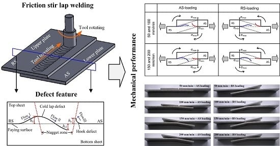
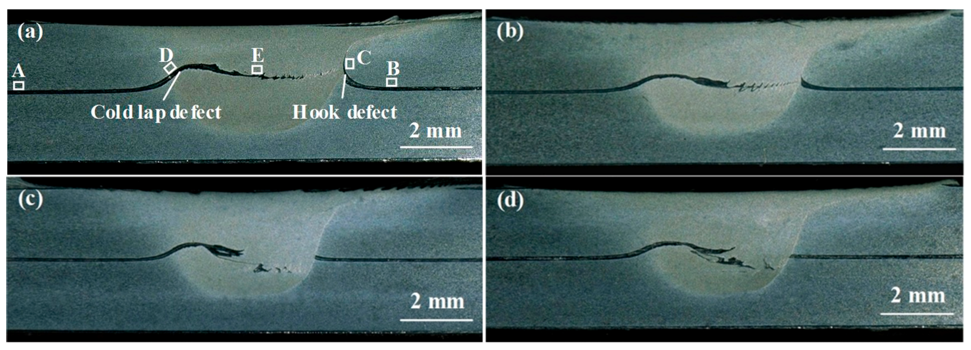
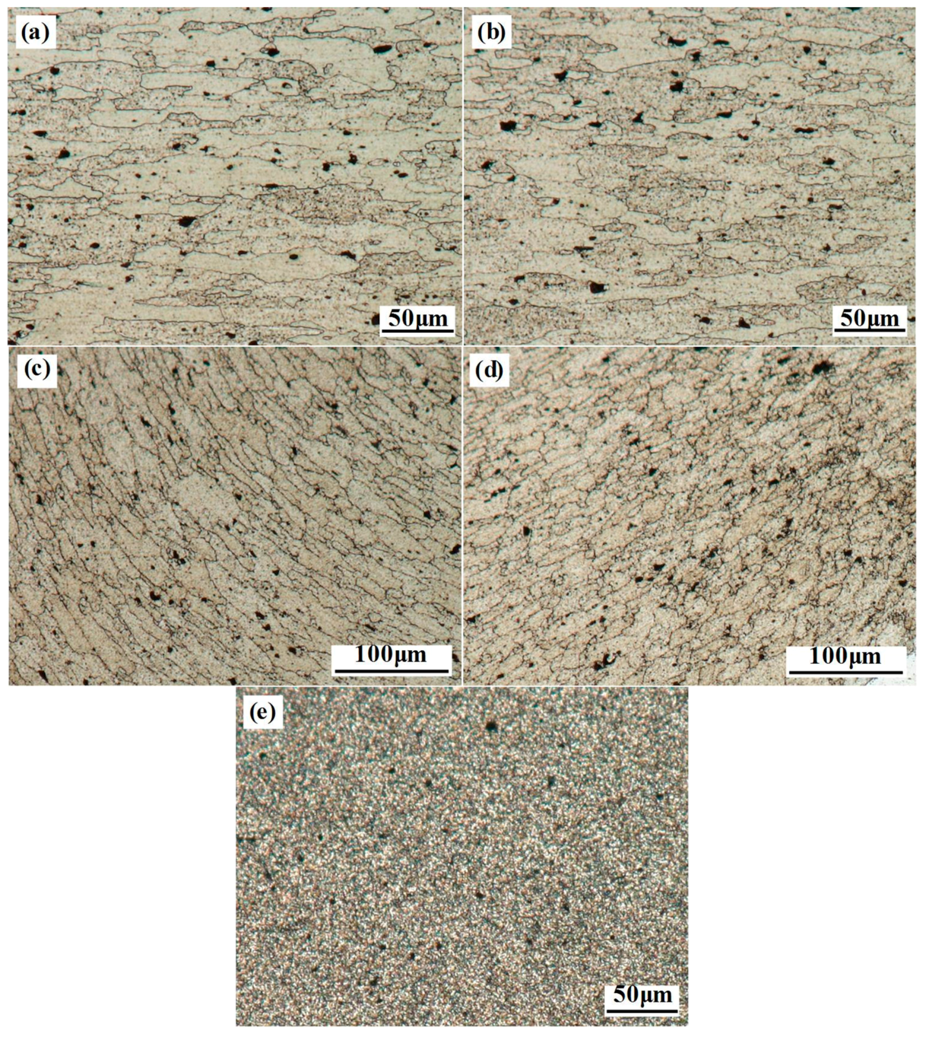
3.1. Defect Features of Lap Joints

Figure 2 shows the cross-sections of FSLW joints. Note that the RS is on the left while the AS is on the right for each cross-section in the figure and throughout the whole paper, and zones A–E shown in Figure 2a represent the locations where microstructure analyses were conducted at 50 mm/min. Two types of welding defects are present in all the lap joints, i.e., the hook defect and cold lap defect, as marked in Figure 2a. In essence, the profiles of defects result from the material flow patterns at the faying surface during FSLW (see Figure 3). In FSLW, the material around the tool at the RS first exhibits an upward flow trend under the shearing effect of the threaded tool pin (i.e., Flow I in Figure 3), and then flows downward to fill the pin cavity at the rear of the tool (i.e., Flow II in Figure 3). Driven by the rotation of the tool pin, the initial faying surface adjacent to the nugget zone at the AS is directed upwards at an inclination angle towards the weld surface and then arrested at the nugget extremity (see Flow III in Figure 3), inducing the formation of the hook defect.
The formation mechanism of the defects in lap joints can be further illustrated from the microstructure characteristics adjacent to the defects. Figure 4 gives the grain structures extracted from zones A–E in Figure 2a, which are corresponding to the base metal (BM), heat affected zone (HAZ), thermo-mechanically affected zone (TMAZ) on the AS, TMAZ on the RS and the weld nugget zone (WNZ) of the lap joint welded at 50 mm/min, respectively. The initial base material is characterized by elongated grain structures, as seen in Figure 4a. The HAZ only experiences welding thermal cycles during FSW and no deformation occurs in the faying surface at this zone, thus the HAZ exhibits similar grain structures as the BM (see Figure 4a,b). The material around the tool is plastically deformed during tool rotation and forms the TMAZ on both sides of the weld. The similar flow trends of the extruded grains and the lap defects in TMAZ at each side are both reflections of the material flow patterns by passage of welding tool (see Figure 4c,d). The WNZ undergoes intense plastic deformation during welding and is featured by fine equiaxed grain structures due to dynamic recrystallization (see Figure 4e).
The formation of the defects mentioned above results in the sheet thinning of lap joints. The hook defect only reduces the effective thickness of the top sheet; however, the cold lap defect can not only lead to the effective thickness reduction in the top sheet, but it can also result in the thinning of the bottom sheet when the welding speed is above 150 mm/min (see Figure 2c,d). This is different from that commonly observed in previous investigations, where only the top sheet thinning occurs due to the cold lap defect [6,13,14,15]. In order to quantify the levels of sheet thinning caused by the both defects, Figure 5 plots the height of the hook and cold lap defects, which was measured in the optical microscope. The defect height in both the top and bottom sheets is considered in this paper, and the total height of the hook defect or cold lap defect is defined as the sum of the maximum vertical distance from the defect to the initial faying surface in the top and bottom sheets (i.e., ha for the hook defect and hr1 + hr2 for the cold lap defect, as marked in Figure 3).
When the welding speed is increased, the upward movements of the initial faying surface caused by Flow I and Flow III are both limited due to the weakening of the pin shearing effect, leading to the notable decrease of ha and hr1. On the other hand, an increase in welding speed can not only increase the pin cavity volume at per tool rotation, but it can also weaken the tool pin shearing effect at per unit length of weld. These two factors are both favorable for the downward flow of the pin sheared material, and thus the downward motion of the cold lap defect profile caused by Flow II is progressively improved with the welding speed. Above 150 mm/min, the cold lap defect even extends into the bottom sheet of the lap joints (see Figure 2c,d). Since the height of the cold lap defect is decreased in the top sheet and simultaneously increased in the bottom sheet when the welding speed is increased, the total height of the cold lap defect (hr1 + hr2) does not vary so evidently with the welding speed as that of the hook defect does (see Figure 5).

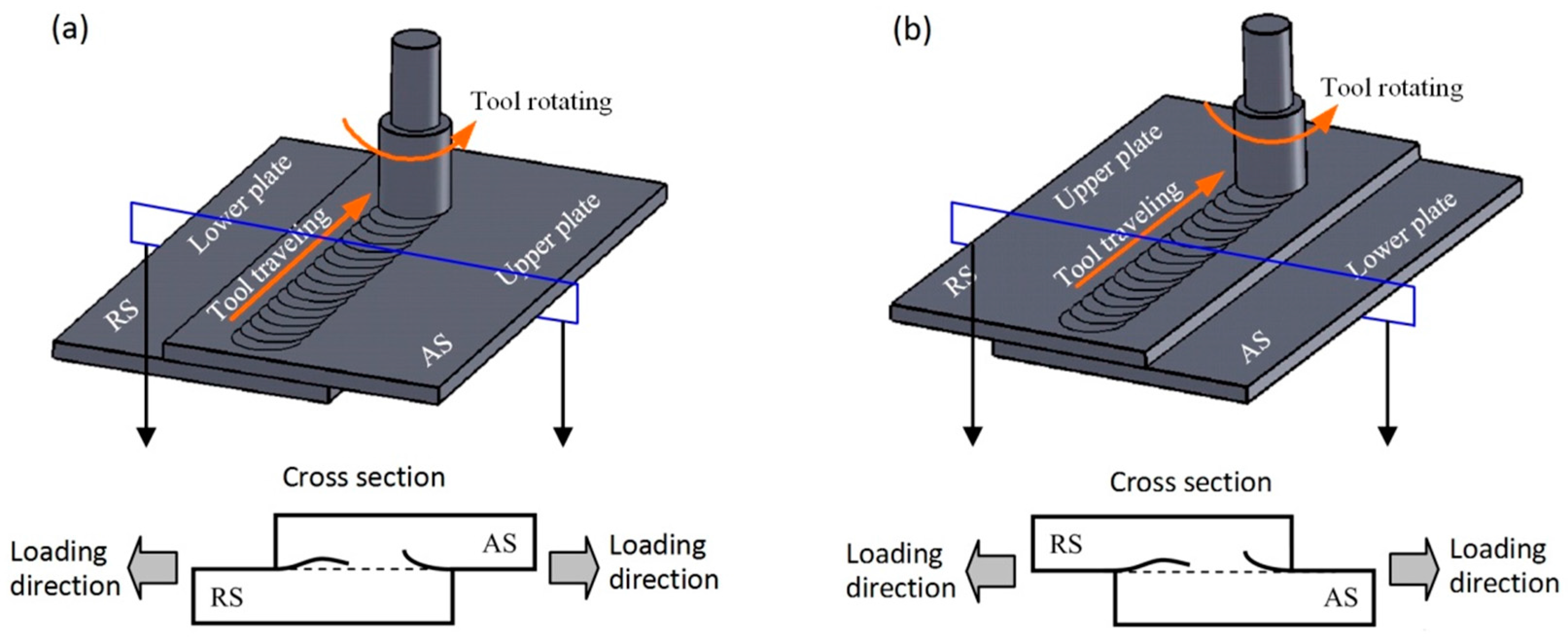
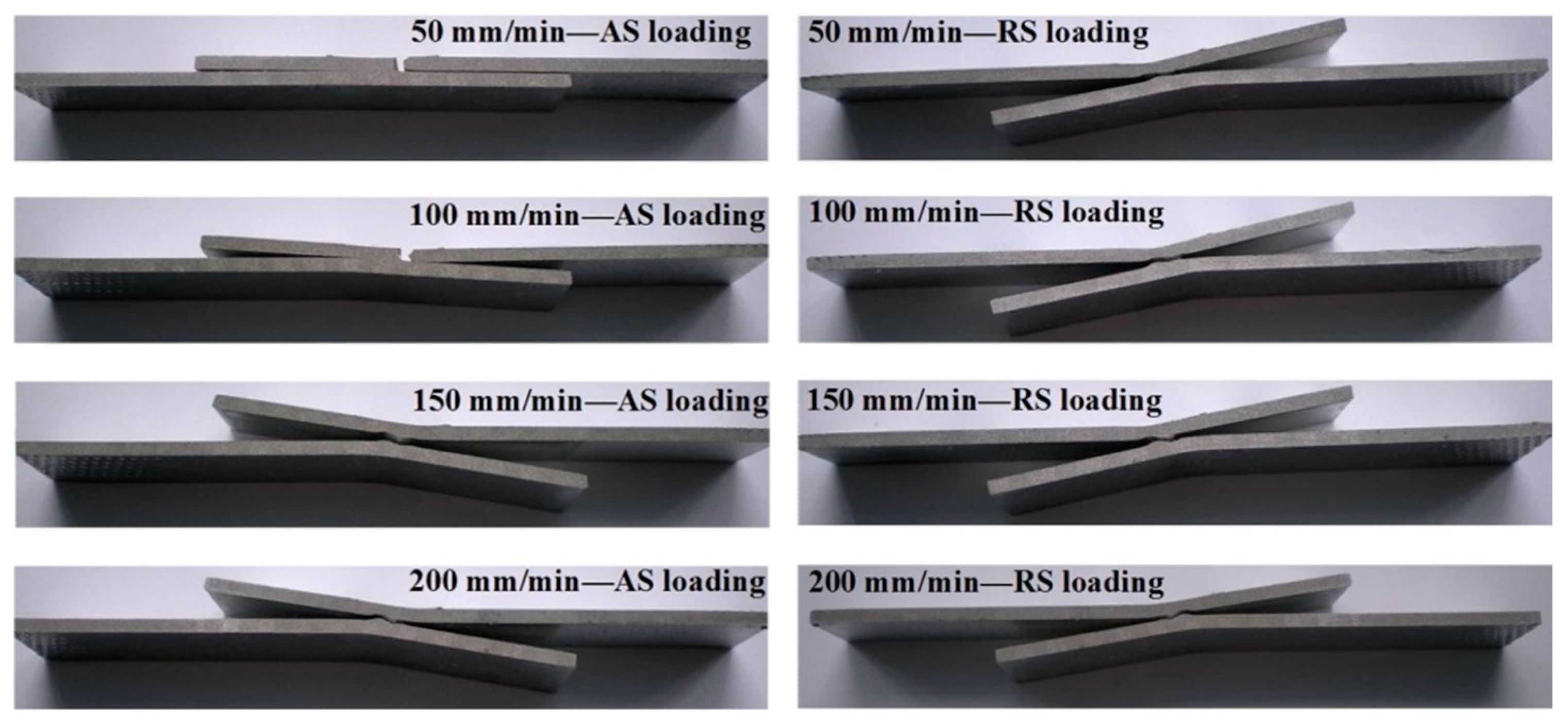
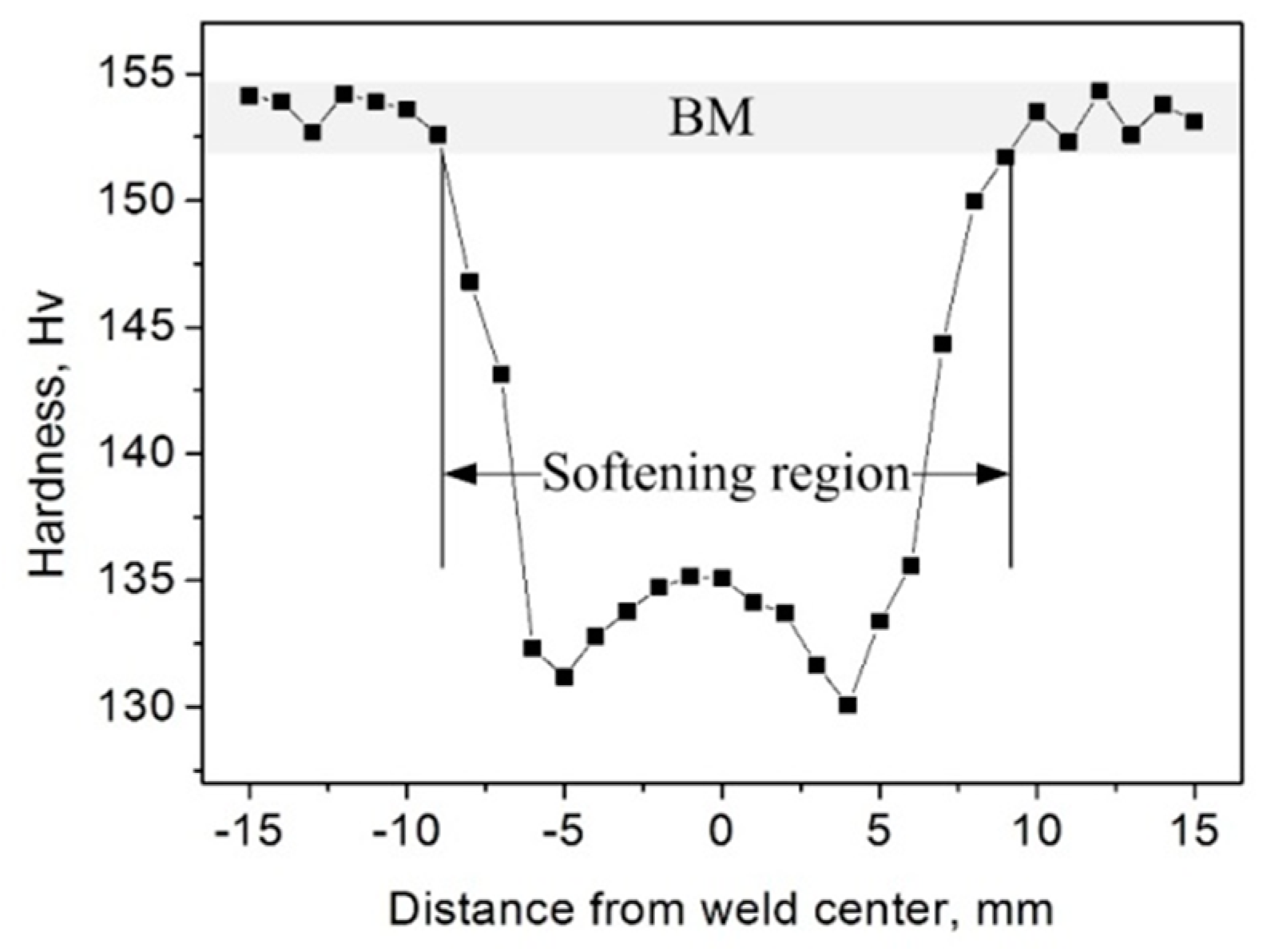
3.2. Mechancial Performance of Lap Joints

The lap shear test was conducted to evaluate the mechanical performance of FSLW joints. During the test, two fracture modes are observed. For Mode I, fracture occurs in the hook defect on the AS, and the final fracture path is nearly normal to the weld top surface (see Figure 6 and Figure 7a). In Mode II, however, the fracture just occurs in the cold lap defect (see Figure 6 and Figure 7b). Apparently, the pre-crack is more favorable for occurring at the hook and cold lap defects under tensile loading, and thus the two fracture modes are actually introduced on the basis of fracture mechanics definitions.
In the AS loading configuration, when the welding speed is increased from lower values (50 and 100 mm/min) to higher values (150 and 200 mm/min), the fracture feature of the lap joints is changed from Mode I to Mode II, and the fracture strength of AS-loaded lap joints is progressively increased with the welding speed, as revealed in Figure 6 and Figure 8. For the RS loading configuration, however, all the joints are fractured in Mode II during the tensile test, and the fracture strength of the RS-loaded lap joints varies slightly with the welding speed.
During the tensile test, the tensile force whose direction is fixed is applied on the original faying surface of the lap joints. In contrast, the hook and cold lap defects, where the crack is first generated and the relative movement of both sheets takes place, exhibit curved features (see Figure 2). Apparently, the tensile direction and the movement direction of the lap sheets do not take place at the same surface, the additional bending moment then leads to the occurrence of local bending and the rotation of both sheets, as shown in Figure 9. This phenomenon was also emphasized in previous studies, and has been simulated in the research of Yazdanian [7], Babu [8] and Fersini [16] et al. The present result reveals that the joints with larger rotating angles require more time to reach failure during lap shear tests, and thus the rotating level of the lap sheets actually indicates the deformation ability of the lap joints, i.e., the difficult degree for failure to occur during the tensile test. Owing to this, the rotating angle and the fracture strength exhibit similar evolving trends with the welding speed for both AS- and RS-loaded lap joints (see Figure 8 and Figure 9). As the welding speed is increased, the trend of a rapid increase in the rotating angle is clear for the AS-loaded joints; in comparison, the rotating angle of the RS-loaded lap joints shows a slight variation.
The effect of loading configuration on joint performance also varies with the welding speed. At lower welding speeds of 50 and 100 mm/min, the RS-loaded lap joints show superior fracture strength to the AS-loaded lap joints. When the welding speed is high (150 and 200 mm/min), the fracture strength of AS-loaded lap joints is larger than that of RS-loaded lap joints.

4. Discussion

4.1. Evolution of Tensile Properties with Welding Speed

The mechanical properties of FSLW joints can be influenced by several factors. The sheet thinning level caused by the hook and cold lap defects has been demonstrated to play a prominent role in determining the performance of lap joints [6,7,8,9,10,11,12,13]. Yuan et al. [13] reported that the crystallographic texture was another factor that influenced the fracture load and fracture path of FSLW joints of AZ31 magnesium alloy. Meanwhile, as far as the heat-treatable aluminum alloy is concerned, the thermal effect during FSW can cause local softening to occur in the joint, leading to the reduction in mechanical properties of the weld relative to the BM [17,18]. The local softening phenomenon is also observed in the present study, as seen in Figure 10. The 7B04 aluminum alloy possesses the hardness of 152–155 Hv, while the weakest region of the weld only presents the hardness value of 130–135 Hv, much lower than that of the BM. Yazdanian et al. [7] pointed out that the softening of the HAZ could be an important factor in determining the tensile properties of lap joints of heat-treatable aluminum alloys, because some of the FSLW joints were found to fail in the HAZ rather than along the hook or cold lap defect during the tensile test. However, for the present study, it should be noted that all the lap joints are fractured in the hook and cold lap defects under tensile loading. The fracture strength and the level of sheet thinning induced by the defects exhibit similar evolving trends as the welding speed. Therefore, the tensile properties of FSLW joints are believed to be largely related to the sheet thinning level, i.e., the height of the defects.
When the welding speeds are low (50 and 100 mm/min), the hook defects at the AS are characterized by a large height and show a sharp curved feature (see Figure 2a,b). In this case, the AS-loaded lap joints fail in the hook defects and present lower fracture strength with a lesser extent of local bending and rotation (see Figure 6, Figure 8 and Figure 9). As the welding speed is increased, the height of the hook defect is dramatically decreased (see Figure 5). The cold lap defect that causes the larger extent of sheet thinning is then more favorable for a fracture to occur during AS loading, and an increase of fracture strength with welding speed is observed (see Figure 8). For the case of RS loading, the failure of all the joints progresses along the cold lap defect (see Figure 6). The level of sheet thinning resulting from the cold lap defect varies slightly with the welding speed, and thus the RS-loaded lap joints do not vary significantly in fracture strength and exhibit a nearly similar rotating angle during lap shear tests as the welding speed is increased (see Figure 8 and Figure 9).

4.2. Effect of Loading Configuration on Joint Properties

Previous investigations have reported that the FSLW joints showed different mechanical performances between AS and RS loading configurations due to the different characteristics of hook and cold lap defects. In the research of Cederqvist [4] and Buffa [11] et al., the AS-loaded lap joints showed higher fracture strength than the RS-loaded lap joints. In contrast, Yang [12] and Yuan [13] claimed that the joint properties obtained in RS loading were superior to those obtained in AS loading. In the present study, both of the cases are observed, and the results indicate that the affecting characteristic of loading configuration on joint performance is actually variable with the welding speed.
To illustrate the intrinsic reason for the affecting characteristics, Figure 11 plots the schematic views of the tensile behavior of lap joints under different loading configurations. The hook and cold lap defects are described by red and blue lines, respectively. The big gray arrow indicates the path of load applied on the initial faying surface of the lap joints. The level of tensile stress is marked by the dash line, which is progressively decreased from a maximum (σmax) at the loaded end to a minimum (σmin) at the unloaded end in the top and bottom sheets.
When the welding speeds are low (50 and 100 mm/min), the hook defects with great height are formed at the AS (see Figure 2 and Figure 5). During AS loading, the sharp curved character of the hook feature introduces a significant stress concentration at the tip of the hook. The lap joints are fractured in the hook defects during the tensile test and exhibit poor tensile properties. In contrast, for the case of RS loading, the maximum stress is achieved at the RS of the top sheet (see Figure 11). Therefore, the cold lap defect is the favorable location for fracture during the lap shear test. The slightly upward then downward movement of the cold lap defect can remarkably reduce the stress concentration and thus retard the crack generation and propagation. Consequently, greater fracture strength in RS loading is obtained in contrast to AS loading.
When the welding speed is increased to large values (150 and 200 mm/min), the height of the hook defect is dramatically decreased. Under such a condition, the cold lap defect is more favorable for crack generation and propagation than the hook defect, and thus the AS- and RS-loaded lap joints both fail along the cold lap defect. The stress applied to the cold lap defect in AS loading is smaller than that in RS loading during the tensile test (see Figure 11), which makes the crack propagation along the cold lap defect more difficult during AS loading. As a consequence, the AS loading configuration leads to stronger joint properties than the RS loading configuration.
Above all, FSLW joints tend to be fractured at the location that experiences the largest extent of sheet thinning or where the maximum tensile stress is located. From this point of view, two aspects should be considered in order to obtain the high performances of lap joints. Firstly, a relatively high welding speed should be applied in FSLW on the premise of avoiding welding defects such as grooves and voids, since the high welding speed tends to lower the sheet thinning level on the AS of the lap joint. Secondly, the loading side of the joint, AS or RS, should possess a larger effective thickness, because in such a case the stress acting on the weakest location of joint is relatively low. By taking these two measures, the FSLW joint needs to experience a large force of local bending and rotation for crack generation, which improves the load-carrying ability of the lap joint and finally leads to superior joint properties.

5. Conclusions

Based on the present investigation, the results of significance are drawn as follows:
(1)
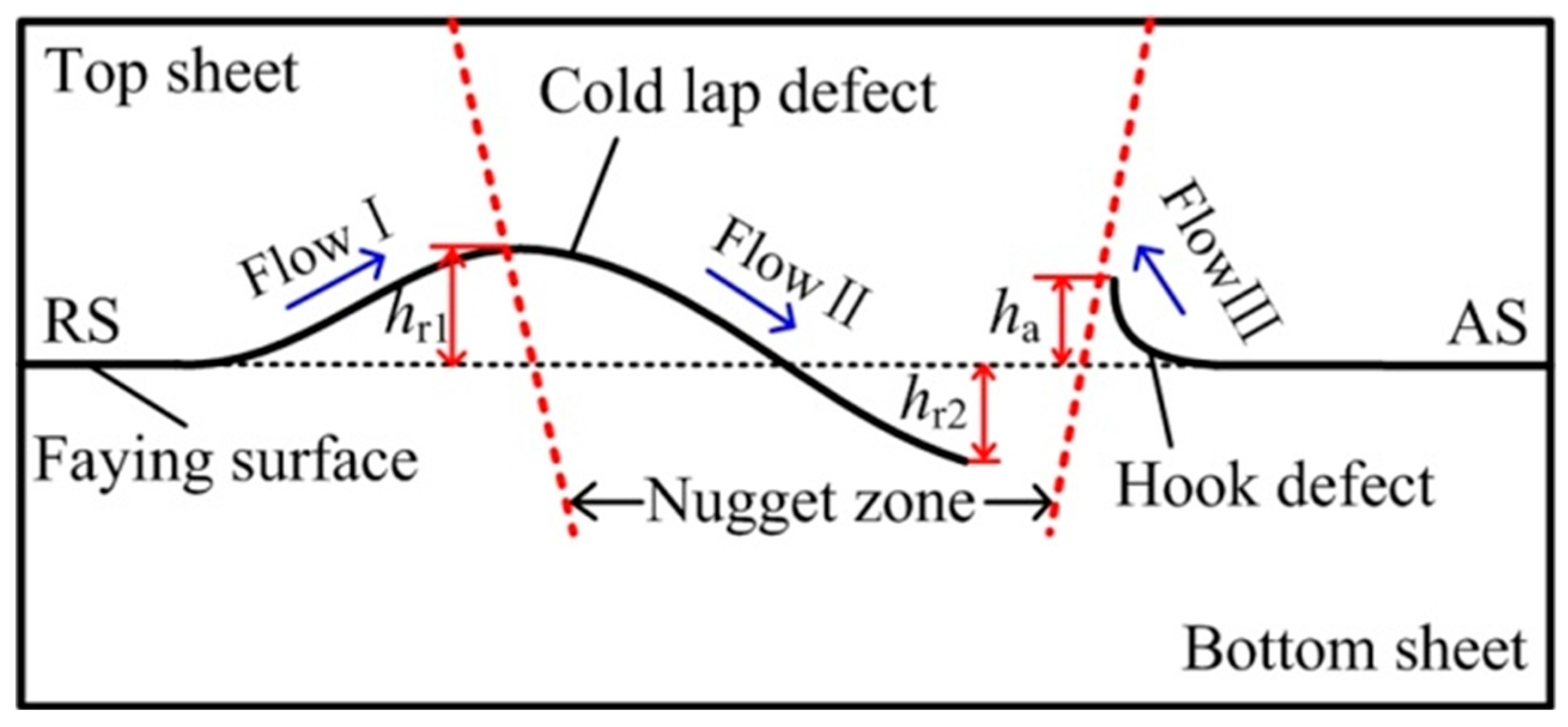
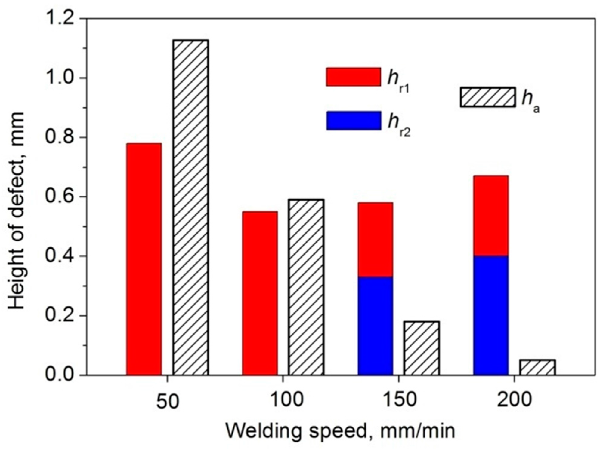
The increase of welding speed can remarkably limit the upward motion of the initial faying surface, which lowers the level of top sheet thinning induced by the hook defect. The cold lap defect can result in the reduction of effective thickness in both the top and bottom sheets. The height of the cold lap defect is decreased in the top sheet but gradually increased in the bottom sheet when the welding speed is increased, leading to a slight variation in the total height of the cold lap defect with the welding speed.
(2)
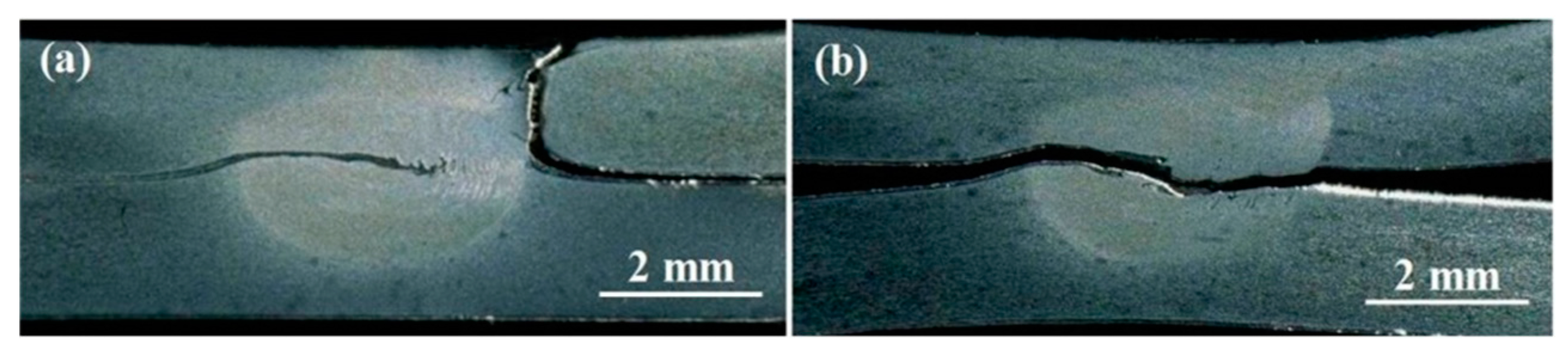
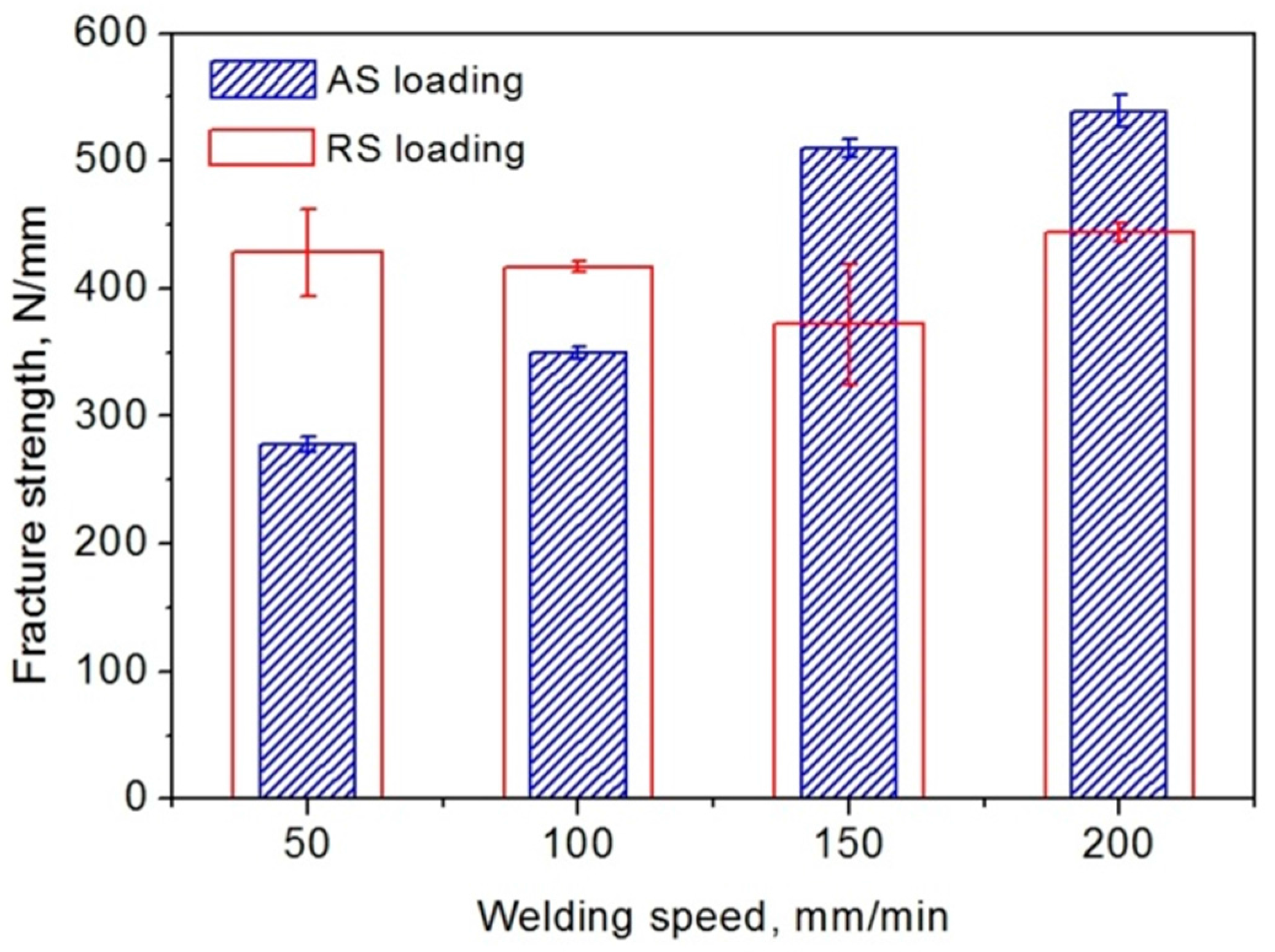
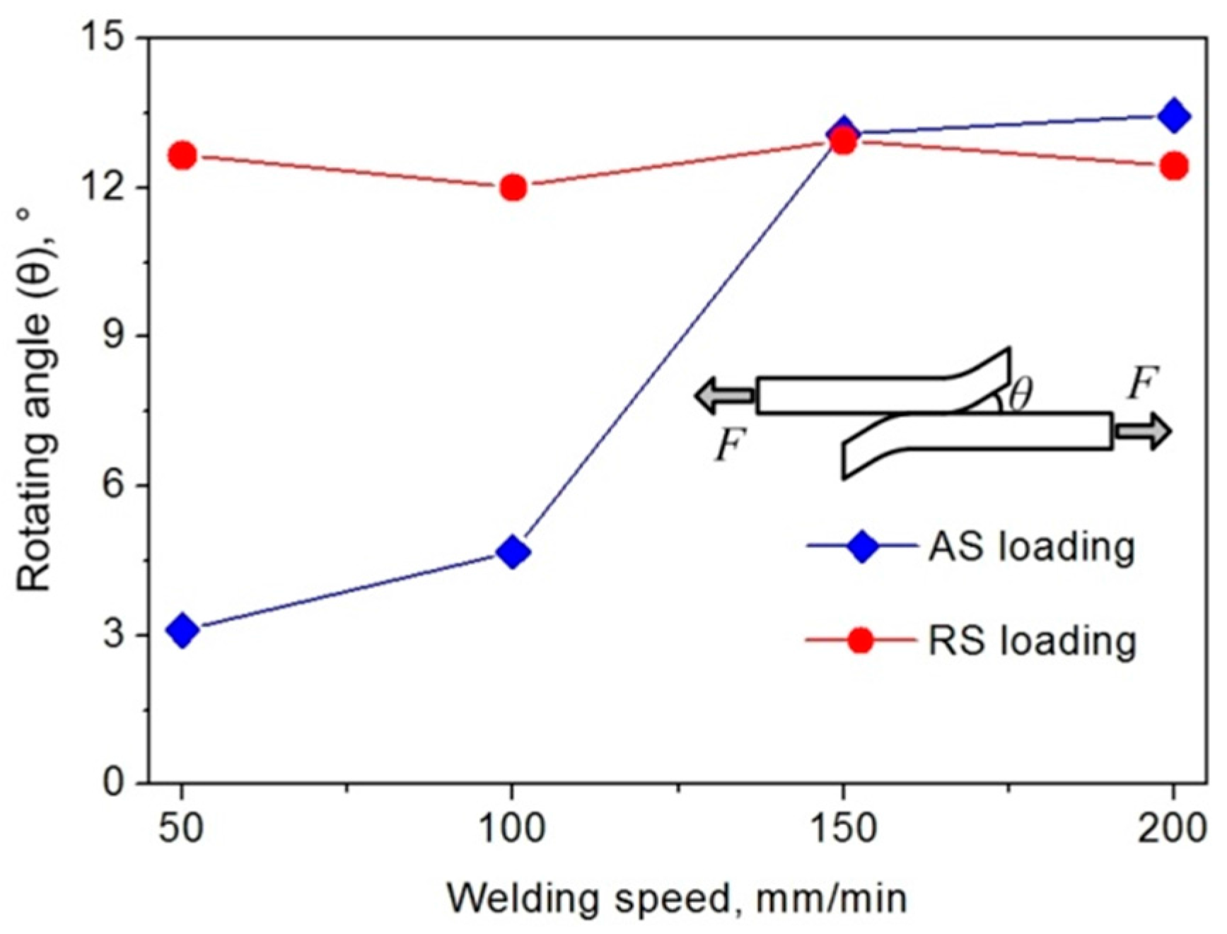
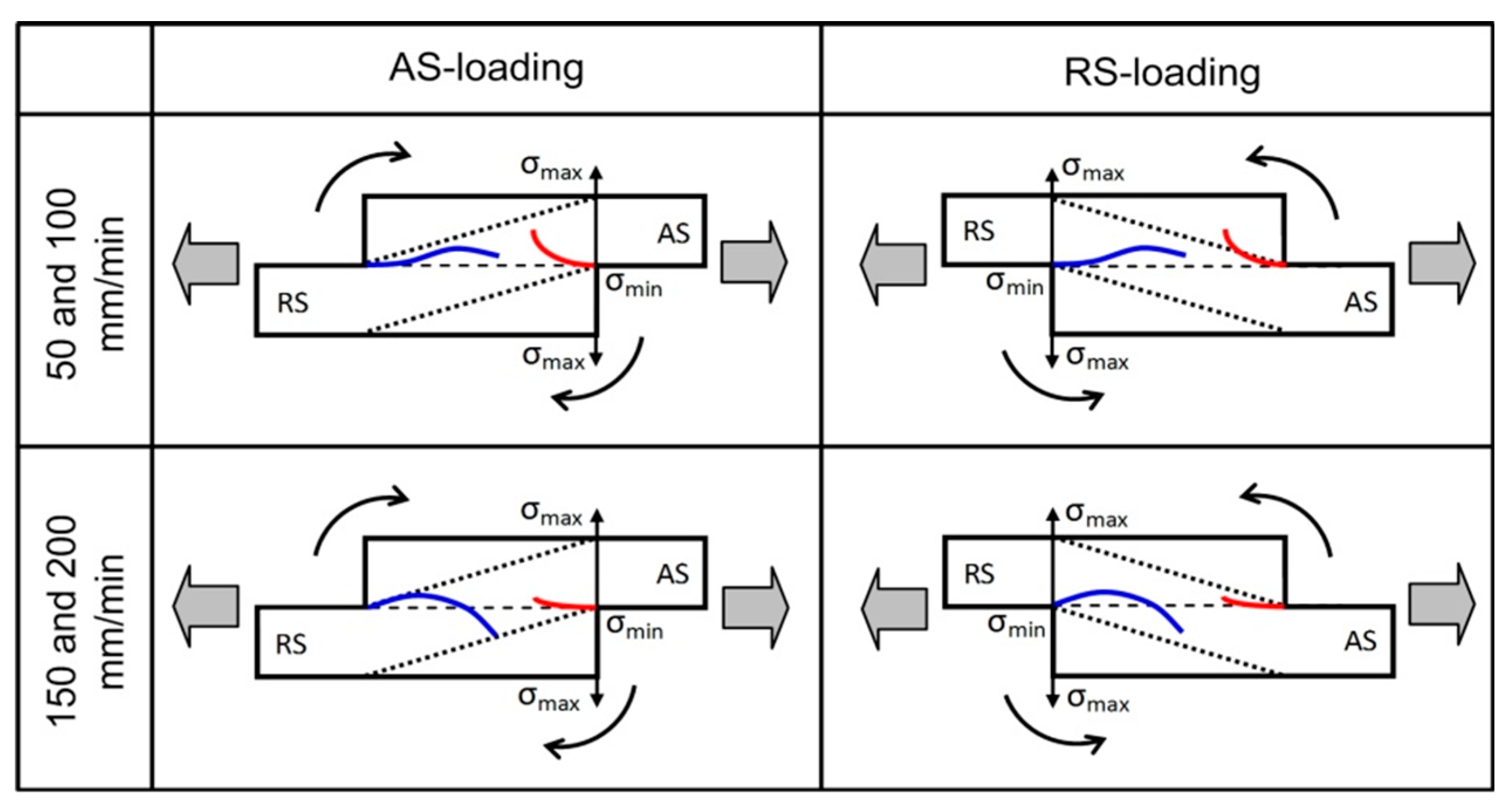
The tensile properties of FSLW joints are largely related to the level of sheet thinning caused by the hook and cold lap defects. In the AS loading configuration, the fracture strength of AS-loaded lap joints is significantly increased with increasing welding speed, while for the RS loading configuration, the fracture strength of RS-loaded lap joints varies slightly with the welding speed. Local bending and rotating occurred in the lap joints during the tensile test. The rotating angle of the lap sheets and the fracture strength of the lap joints exhibit similar evolving trends with the welding speed in both AS and RS loading configurations.
(3)
The affecting characteristic of loading configuration on joint performance is dependent on the welding speed. At lower welding speeds, the AS-loaded lap joints show lower fracture strength than the RS-loaded lap joints. When the welding speed is high, the AS-loaded lap joints then present larger tensile properties than RS-loaded lap joints. In order to obtain the high performance of lap joints, a relatively high welding speed should be applied during FSLW. Meanwhile, the loading side of the joint, AS or RS, should possess a larger effective thickness in the joint.

Acknowledgments

The authors are grateful to be supported by National Natural Science Foundation of China (Grant No. 51505471) and Special Fund for Youth Innovation Promotion Association, Chinese Academy of Sciences (Grant No. 2015162).

Author Contributions

Huijie Zhang and Min Wang conceived and designed the experiments; Huijie Zhang, Xiao Zhang and Guangxin Yang performed the experiments; Zhi Zhu and Tao Yu analyzed the experimental data; Huijie Zhang wrote the paper.

Conflicts of Interest

The authors declare no conflict of interest.

References

  1. Mishra, R.S.; Ma, Z.Y. Friction stir welding and processing. Mater. Sci. Eng. Rep. 2005, 50, 1–78. [Google Scholar] [CrossRef]
  2. Buffa, G.; Fratini, L.; Ruisi, V. Friction stir welding of tailored joints for industrial applications. Int. J. Mater. Form. 2009, 2, 311–314. [Google Scholar] [CrossRef]
  3. Cam, G.; Mistikoglu, S. Recent developments in friction stir welding of Al-alloys. J. Mater. Eng. Perform. 2014, 23, 1936–1953. [Google Scholar] [CrossRef]
  4. Cederqvist, L.; Reynolds, A.P. Factors affecting the properties of friction stir welded aluminum lap joints. Weld. J. 2001, 80, 281–287. [Google Scholar]
  5. Lee, C.Y.; Lee, W.B.; Kim, J.W.; Choi, D.H.; Yeon, Y.M.; Jung, S.B. Lap joint properties of FSWed dissimilar formed 5052 Al and 6061 Al alloys with different thickness. J. Mater. Sci. 2008, 43, 3296–3304. [Google Scholar] [CrossRef]
  6. Yadava, M.K.; Mishra, R.S.; Chen, Y.L.; Carlson, B.; Grant, G.J. Study of friction stir joining of thin aluminium sheets in lap joint configuration. Sci. Technol. Weld. Join. 2010, 15, 70–75. [Google Scholar] [CrossRef]
  7. Yazdanian, S.; Chen, Z.W.; Littlefair, G. Effects of friction stir lap welding parameters on weld features on advancing side and fracture strength of AA6060-T5 welds. J. Mater. Sci. 2012, 47, 1251–1261. [Google Scholar] [CrossRef]
  8. Babu, S.; Ram, G.D.J.; Venkitakrishnan, P.V.; Reddy, G.M.; Rao, K.P. Microstructure and mechanical properties of friction stir lap welded aluminum alloy AA2014. J. Mater. Sci. Technol. 2012, 28, 414–426. [Google Scholar] [CrossRef]
  9. Wang, M.; Zhang, H.J.; Zhang, J.B.; Zhang, X.; Yang, L. Effect of pin length on hook size and joint properties in friction stir lap welding of 7B04 aluminum alloy. J. Mater. Eng. Perform. 2014, 23, 1881–1886. [Google Scholar] [CrossRef]
  10. Urso, G.D.; Giardini, C. The influence of process parameters and tool geometry on mechanical properties of friction stir welded aluminum lap joints. Int. J. Mater. Form. 2010, 3, 1011–1014. [Google Scholar]
  11. Buffa, G.; Campanile, G.; Fratini, L.; Prisco, A. Friction stir welding of lap joints: Influence of process parameters on the metallurgical and mechanical properties. Mater. Sci. Eng. A 2009, 519, 19–26. [Google Scholar] [CrossRef]
  12. Yang, Q.; Li, X.; Chen, K.; Shi, Y.J. Effect of tool geometry and process condition on static strength of a magnesium friction stir lap linear weld. Mater. Sci. Eng. A 2011, 528, 2463–2478. [Google Scholar] [CrossRef]
  13. Yuan, W.; Carlson, B.; Verma, R.; Szymanski, R. Study of top sheet thinning during friction stir lap welding of AZ31 magnesium alloy. Sci. Technol. Weld. Join. 2012, 17, 375–380. [Google Scholar] [CrossRef]
  14. Xu, X.D.; Yang, X.Q.; Zhou, G.; Tong, J.H. Microstructures and fatigue properties of friction stir lap welds in aluminum alloy AA6061-T6. Mater. Des. 2012, 35, 175–183. [Google Scholar] [CrossRef]
  15. Dubourg, L.; Merati, A.; Jahazi, M. Process optimization and mechanical properties of friction stir lap welds of 7075-T6 stringers on 2024-T3 skin. Mater. Des. 2010, 31, 3324–3330. [Google Scholar] [CrossRef]
  16. Fersini, D.; Pirondi, A. Fatigue behavior of Al 2024-T3 friction stir welded lap joints. Eng. Fract. Mech. 2007, 74, 468–480. [Google Scholar] [CrossRef]
  17. Starink, M.J.; Seschamps, A.; Wang, S.C. The strength of friction stir welded and friction stir processed aluminum alloys. Scr. Mater. 2008, 58, 377–382. [Google Scholar] [CrossRef]
  18. Fratini, L.; Buffa, G.; Shivpuri, R. Mechanical and metallurgical effects of in process cooling during friction stir welding of AA7075-T6 butt joints. Acta Mater. 2010, 58, 2056–2067. [Google Scholar] [CrossRef]
Figure 1. Different loading configurations in friction stir lap welding (FSLW): (a) advancing side (AS) loading; (b) retreating side (RS) loading [9].
Metals 06 00087 g001
Figure 2. Cross-sections of the lap joints obtained at different welding speeds: (a) 50 mm/min; (b) 100 mm/min; (c) 150 mm/min; (d) 200 mm/min; A–E marked in (a) reflect the locations where microstructure analyses were conducted.
Metals 06 00087 g002
Figure 3. Schematic view of material flow during FSLW; note that the border of nugget zone is represented by the red dashed lines.
Metals 06 00087 g003
Figure 4. Microstructures extracted from different zones of the FSLW joint welded at 50 mm/min: (a) base metal (BM); (b) heat affected zone (HAZ); (c) thermo-mechanically affected zone (TMAZ) at AS; (d) TMAZ at RS; (e) weld nugget zone (WNZ).
Metals 06 00087 g004
Figure 5. Height values of the hook and cold lap defects formed at different welding speeds; ha refers to the height of the hook defect at AS, while hr1 and hr2 represent the heights of the cold lap defects in the top and bottom sheets at RS, respectively.
Metals 06 00087 g005
Figure 6. Fracture features of the lap joints.
Metals 06 00087 g006
Figure 7. Enlarged views of the failed joint (100 mm/min): (a) AS loading; (b) RS loading [9].
Metals 06 00087 g007
Figure 8. Fracture strength of the lap joints obtained at different welding speeds.
Metals 06 00087 g008
Figure 9. Rotating angle of the lap sheets during the lap shear test.
Metals 06 00087 g009
Figure 10. Hardness profile measured across the middle of the top sheet of a FSLW joint (100 mm/min).
Metals 06 00087 g010
Figure 11. Schematic views of tensile behavior of lap joints under different loading configurations.
Metals 06 00087 g011
Table 1. Chemical compositions and mechanical properties of 7B04-T74 aluminum alloy.
Chemical Compositions (wt. %)Mechanical Properties
AlZnMgCuMnFeCrTensile StrengthElongation
Bal.5.752.511.680.260.200.15486 MPa11%

