Article

Ti/Al Multi-Layered Sheets: Differential Speed Rolling (Part B)

1
Leibniz Institute for Solid State and Materials Research Dresden (IFW Dresden), Helmholtzstr. 20, 01069 Dresden, Germany
2
Institut für Werkstoffwissenschaft, Technische Universität Dresden, 01062 Dresden, Germany
3
Institut für Werkstoffwissenschaft, Technische Universität Bergakademie Freiberg, Gustav-Zeuner-Str. 5, 09599 Freiberg, Germany
4
Osaka Municipal Technical Research Institute, 1-6-50 Morinomiya, Joto-ku, Osaka 5368553, Japan
5
Institut für Strukturphysik, Technische Universität Dresden, 01062 Dresden, Germany
6
Erich Schmid Institut für Materialwissenschaft, Österreichische Akademie der Wissenschaft, Jahnstraße 12, A-8700 Leoben, Austria
7
Department Materialphysik, Montanuniversität Leoben, Jahnstraße 12, A-8700 Leoben, Austria
*
Author to whom correspondence should be addressed.
Metals 2016, 6(2), 31; https://doi.org/10.3390/met6020031
Submission received: 26 November 2015 / Revised: 20 January 2016 / Accepted: 26 January 2016 / Published: 2 February 2016

Abstract

:
Differential speed rolling has been applied to multi-layered Ti/Al composite sheets, obtained from accumulative roll bonding with intermediate heat treatments being applied. In comparison to conventional rolling, differential speed rolling is more efficient in strengthening the composite due to the more pronounced grain refinement. Severe plastic deformation by means of rolling becomes feasible if the evolution of common rolling textures in the Ti layers is retarded. In this condition, a maximum strength level of the composites is achieved, i.e., an ultimate tensile strength of 464 MPa, while the strain to failure amounts to 6.8%. The deformation has been observed for multi-layered composites. In combination with the analysis of the microstructure, this has been correlated to the mechanical properties.

Graphical Abstract

1. Introduction

A key aspect in the production of composite materials lies within the possibility of combining different material properties that are attributed to the individual components of the composite. The specific objective in the development of multi-layered Ti/Al composites is the aim to combine (i) a large tensile strength; (ii) a low mass density, yielding a high specific strength and (iii) a sufficient ductility, allowing further forming processes.
One prerequisite for the production of metal composites is a high forming capability. In the present work, accumulative roll bonding (ARB) is utilized to generate composites hardened by grain- and phase-boundaries. When ARB is applied to two different materials, the phase boundary area per volume doubles for each ARB cycle as long as the layers remain continuous. Hence, the stability of the layers is crucial when aiming at maximum phase boundary area. Part A of this study [1] revealed that the stability of the layers can be maintained by introducing an intermediate heat treatment (IHT) after each individual ARB cycle. However, IHT leads to recovery and, therefore, reduces the effect of strain hardening introduced by rolling.
The present study presents a possibility to overcome this issue. ARB with IHT is utilized to generate multi-layered sheets with individual continuous layers. As mentioned before, IHT prevents an accumulation of strain hardening. The composite can be strengthened further when the finally aimed number of layers has been reached. Further cold working by conventional rolling is possible, but the hardening rate is comparably low as the Ti layers fail by necking and do not further deform. Thus, a high degree of deformation would be required, which results in limitations with respect to the sheet thickness. In order to obtain a higher strain hardening rate, the deformation should have a reasonable shear component. A small amount of shear deformation is also observed for conventionally rolled materials. This shear arises from e.g., friction between sheet and rolls. During conventional rolling, the friction is kept at a low level. However, this can be considerably altered by differential speed rolling (DSR). DSR utilizes different velocities of the upper and lower rolls or, alternatively, differently sized rolls (asymmetric rolling) yielding different surface velocities of the rolls. By this means, DSR induces a significant amount of shear deformation within the rolled material yielding a pronounced grain refinement [2,3,4,5] and a change in texture [2,6,7].
In order to ease the discussion, conventional rolling with similar velocity and size of the working rolls, here referred to as equal speed rolling (ESR), represents the benchmark and reference system to DSR [8]. For ESR, shear deformation is restricted to the near surface region [8,9]. In the case of DSR, the volume that is affected by shear is strongly material dependent as shown in numerous studies on different materials, e.g., steel, copper, aluminium and niobium [3,10,11,12,13,14,15]. Special attention is paid to the investigation of DSR of hexagonal metals such as magnesium [4,16,17,18] and titanium [6,19,20,21]. Hoi Pang Ng et al. combined roll bonding and asymmetric rolling on Ti/Al composite sheets with up to four rolling passes and observed a remarkable higher grain refinement and increasing inter diffusion compared to symmetric ARB [22]. However, the thin Ti layers show considerable necking. Consequently, the layered structure is destroyed and the matrix is capable of deformation. Thus, strengthening of the composite is mainly accomplished by strengthening the Al matrix [22]. In summary, the use of shear deformation in Ti/Al multi-layered sheets is still unrevealed, when (i) the multi-layered architecture has to be preserved during processing and (ii) a high deformation strain has to be achieved.
The aim of this study is to investigate the effect of DSR on multi-layered Ti/Al sheets and to emphasize the influence of the multi-layered structure compared to single material sheets in the response to DSR.

2. Experimental Section

For the present study, pure Ti (99.995%) sheets as well as sheets of the aluminium alloy AA5049 (AlMg 2 Mn 0 . 8 , in the following referred to as Al) with an initial size of 30 mm × 125 mm × 1 mm (width × length × thickness) have been used. For benchmarking purposes, single material sheets were also deformed. All sheets were initially in a recrystallized state. In addition, investigations were performed on a five-layered stack of Al-Ti-Al-Ti-Al that has been roll bonded using a thickness reduction of 50% as well as on a Ti/Al composite being accumulatively roll bonded with six ARB cycles including IHTs at 723 K for 90 min after each ARB cycle under vacuum conditions. This composite is composed of 160 continuous layers. For any details, please refer to part A of this study [1].
DSR experiments were performed at room temperature (RT) utilizing a rolling mill with identical diameters of the working rolls of 250 mm operated at different velocities, i.e., rolling speed ratios, and with different numbers of rolling cycles. The thickness reduction of the sheets per rolling pass was approximately 20%, and deformation was performed with up to four rolling passes, while the ratio of the roll velocities used was 1.1, 1.5, 2.0 and 3.0.
As already mentioned, DSR leads to enhanced shearing. In order to visualize this contribution to deformation, pins of annealed pure copper were inserted into several composite sheets before rolling. This procedure follows the experiments of Sakai [9] and Lee [8], who measured the shearing of metal sheets during rolling and ARB. The response of the material was determined on longitudinal cuts, which also include the pin by scanning electron microscopy (SEM, Zeiss Microscopy, Jena, Germany) and electron backscatter diffraction (EBSD, Oxford Instruments, Abingdon, UK). The metallographic preparation for these studies is described in detail in a previous study [23]. EBSD measurements were done in the upper third of the single material sheets and the 160 layer composite sheets. In the five layer sheets, the EBSD maps were taken within the top layer (Al) and the second-top layer (Ti).
Hardness measurements were executed with two nano hardness tester devices (MTS, Eden Prairie, MN, USA) using identical measurement parameters. The Berkovich indenter penetrates the material at a rate of 0.05 s 1 , while a vibration with a frequency of 45 Hz is superimposed. This facilitates a continuous determination of the hardness at any penetration depth. The hardness of each measurement is averaged for depths ranging from 500 nm to 900 nm because of the large fluctuations at lower depths. For each sample and phase, the values of 15 indents are averaged. Tensile tests were carried out at RT; for any detail, please refer to part A of this study.

3. Results and Discussion

3.1. Differential Speed Rolling of Al and Ti

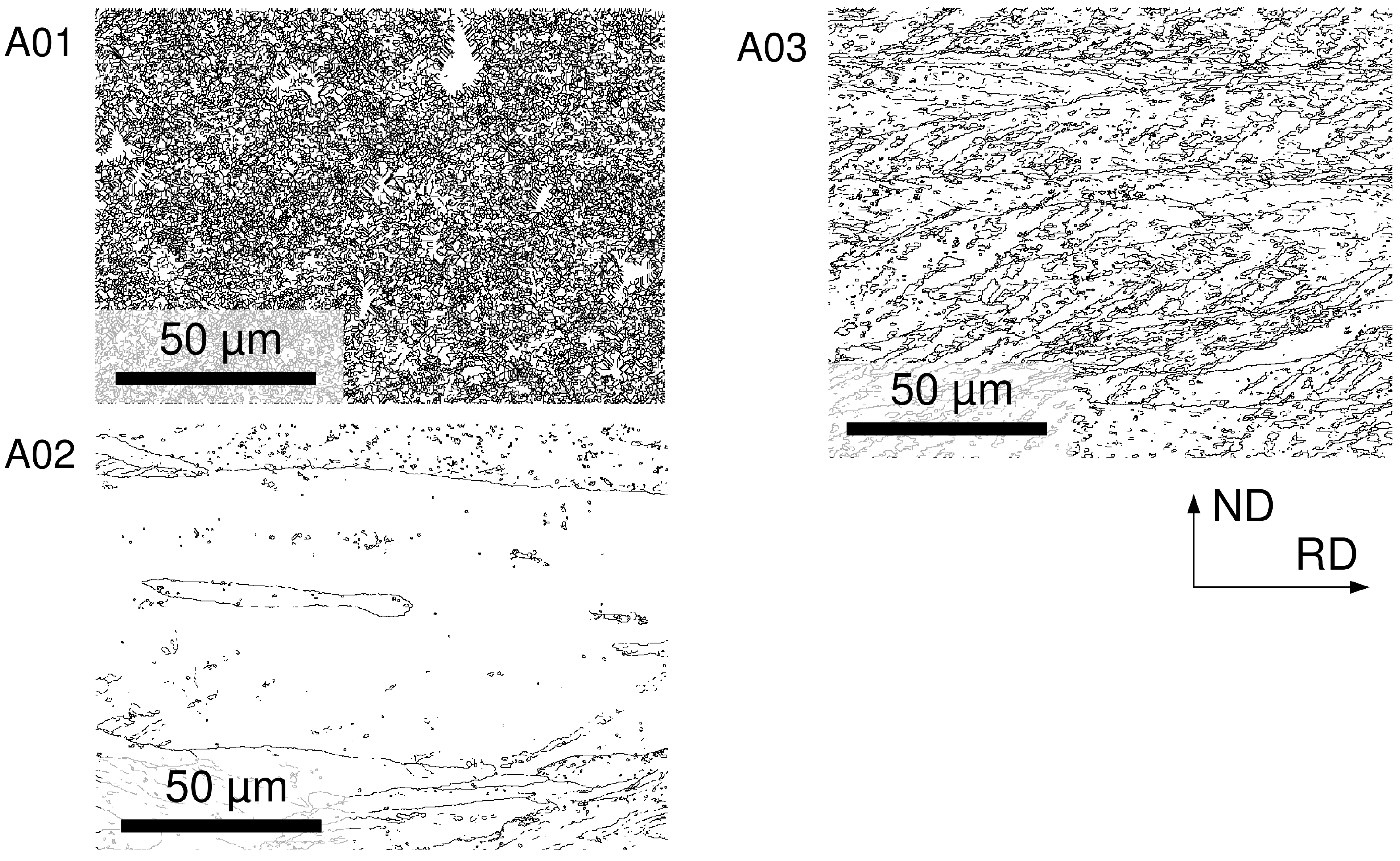
The effect of DSR on the microstructure of Al is shown in Figure 1. All investigations were performed on longitudinal cuts of the specimens at the center of the sheets and the second or third layer from the top.
Figure 1. Grain boundary maps of Al, prepared by DSR. A01: one rolling pass, speed ratio: 1:1; A02: 1 rolling pass, speed ratio: 3.0; A03: four rolling passes, speed ratio: 1:1.
Metals 06 00031 g001
The grain boundary maps shown in Figure 1 were calculated from EBSD micrographs and mark all boundaries with a misorientation angle of 15 and above. The Al sheets were deformed by DSR with different speed ratios and number of rolling passes. An increasing shear deformation, which is related to higher speed ratio results in a significant larger mean grain size after one DSR pass. A similar tendency is observed for a higher shear strain due to an increasing number of DSR passes, as shown for the increase of passes from one to four. A quantitative analysis of the grain sizes is provided in Figure 2.
According to Equation (1) the speed ratio can be transferred to the rolling shear strain γ, assuming plane strain deformation. Therein, v u and v l are the velocities of the upper and lower roll (measured in m/s), respectively, and d is the inside width between the rolls (measured in m).
γ = arctan v u v l 1 d
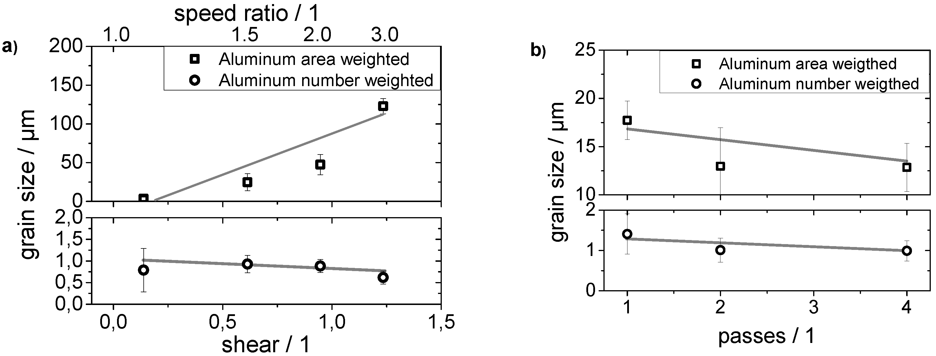
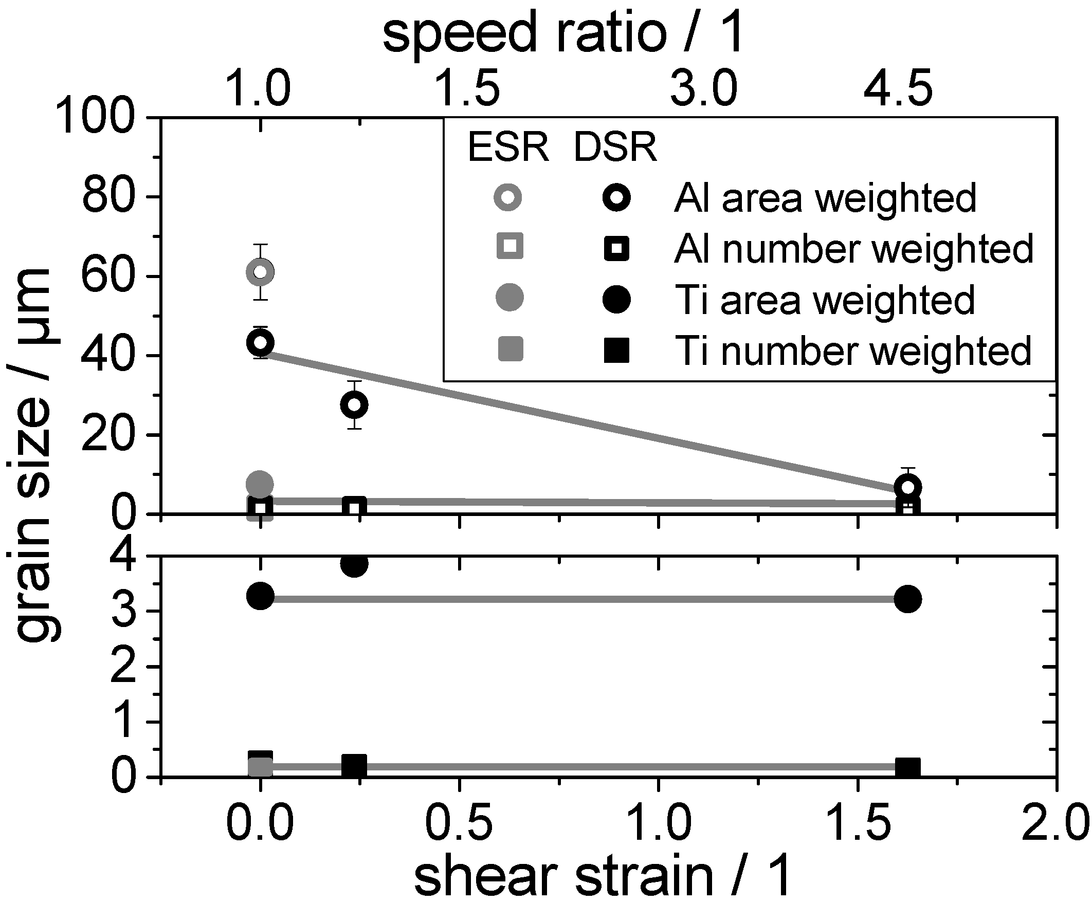
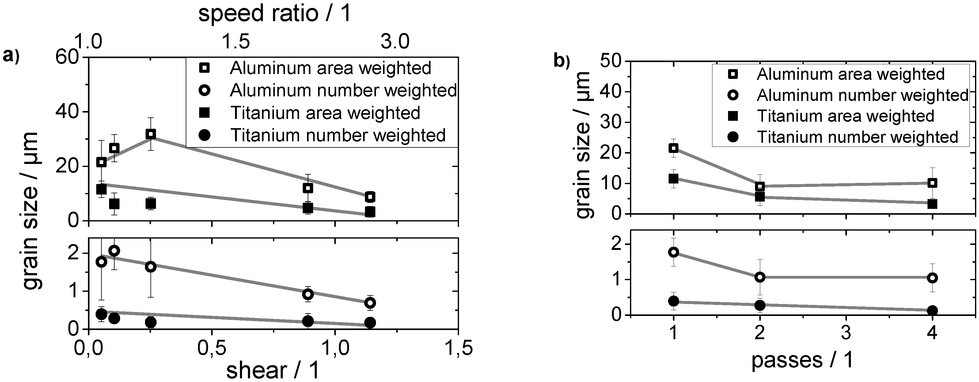
Figure 2a,b show the quantitative analysis of the grain size of the Al sheets being processed by DSR with different speed ratios as well as increasing strain (i.e., number of DSR passes) at a constant speed ratio of 1.1.
Figure 2. (a) Grain size of Al with different weighting methods being applied: grain area with increasing speed ratio, i.e., amount of shear and (b) evolution of the grain size with increasing number of rolling passes (DSR) with a constant speed ratio of 1.1. The weighting methods are described in part A of this study.
Metals 06 00031 g002
The analysis shows a significant increase of the grain size with increasing shear deformation when the mean grain size is weighted upon the area. According to Figure 1, a small number of large grains is responsible for this behavior, which is causing an overestimation of the large grains. In contrast, the arithmetic average shows a slight decrease of the grain size with increasing amount of shear deformation. Furthermore, the grain size also only slightly decreases with increasing number of rolling passes at a constant speed ratio of 1.1, no matter the weighting method.
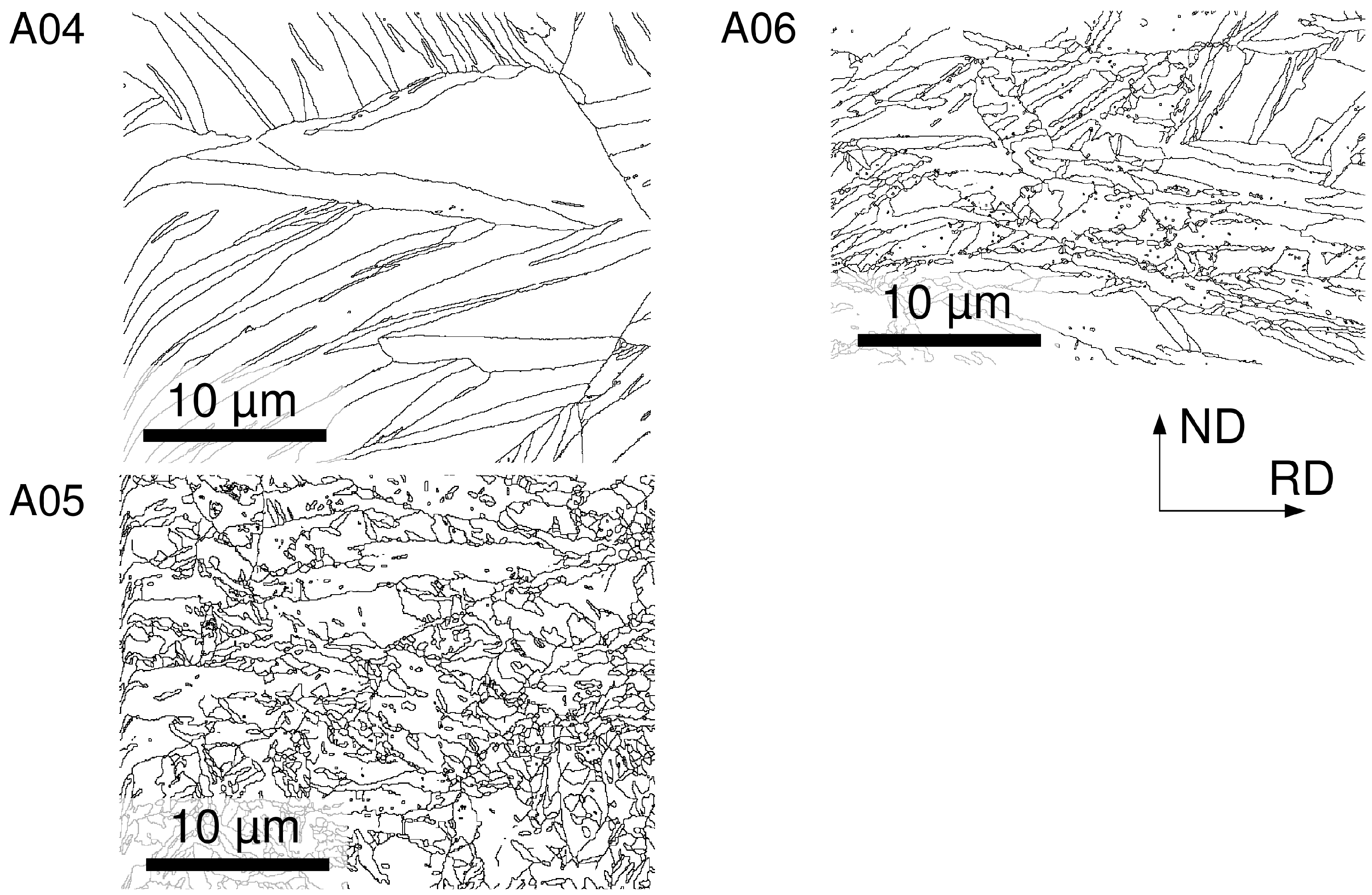
A similar analysis has been made for DSR Ti sheets (The sheets were deformed in the same was as the Al sheets). Figure 3 shows grain boundary maps of Ti.
An increasing shear deformation decreases the mean grain size. This is more evident when comparing the different speed ratios. In order to assess the effect of DSR on the mechanical properties, Al and Ti sheets in the cold rolled condition (as-received), in which the amount of shear deformation can be neglected, have been tensile tested in comparison to those being additionally processed by DSR with a low shear deformation (i.e., speed ratio of 1.1), as shown in Figure 4.
Figure 3. Grain boundary maps (i.e., boundaries with a misorientation angle of 15 degree and above) of DSR Ti. A04: one rolling pass, speed ratio: 1.1; A05: 1 rolling pass, speed ratio: 3.0; A06: four rolling passes, speed ratio: 1.1.
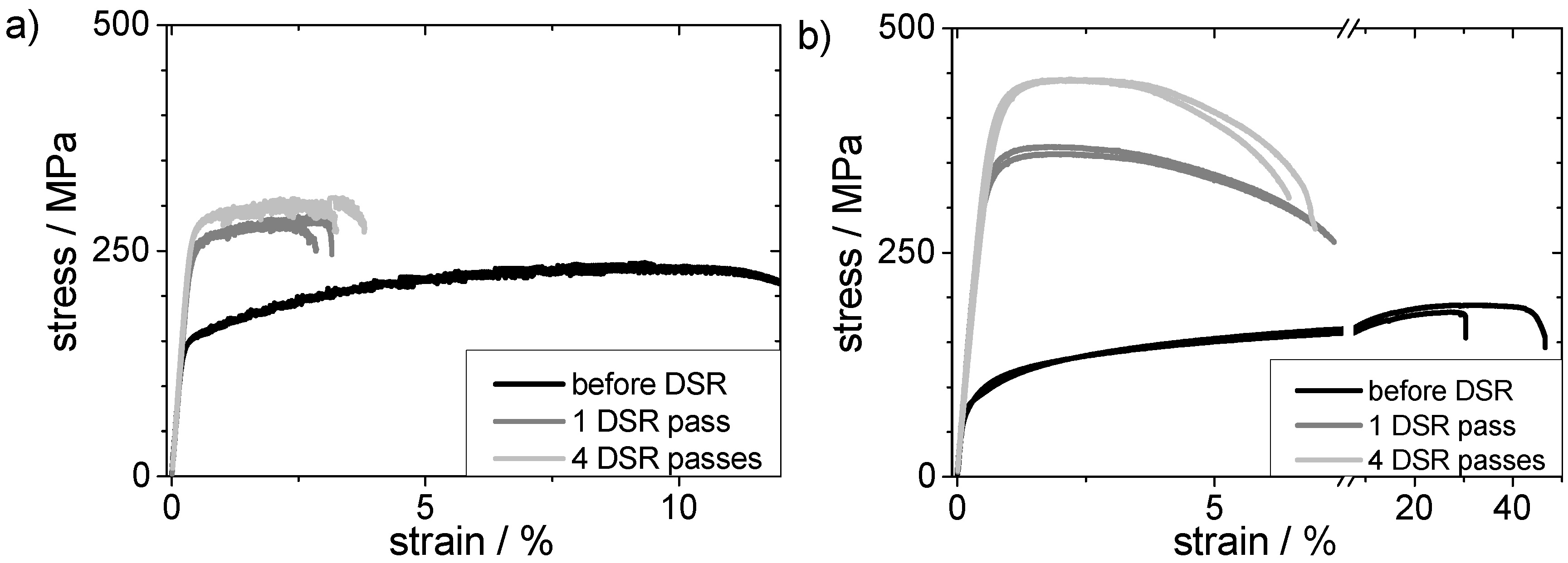
Metals 06 00031 g003
Figure 4. Engineering stress-strain curves for (a) Al and (b) Ti sheets in the cold rolled condition and after one and four DSR passes at a speed ratio of 1:1. Results for two samples in each condition are shown in order to illustrate the occurring variations.
Metals 06 00031 g004
As can be seen from Figure 4, DSR significantly affects the flow behavior. The increase of strength is likely to be caused by a higher dislocation and twin (Ti) density within the materials, which is reflected in significantly decreasing EBSD pattern quality. A significant contribution to the strength according to the Hall–Petch relationship [24,25] can be excluded due to similar grain sizes in all conditions (see Figure 2). DSR also causes a decreasing strain to failure. However, the reduction of ductility is very pronounced due to the shear deformation itself. The ultimate tensile strength (UTS) of Ti is only 190 MPa in the initial state. A single pass of DSR increases the UTS to about 370 MPa and multi-pass DSR further to 460 MPa. The UTS of Al increase is less pronounced. One single DSR pass causes an increase of the UTS from 240 MPa to 280 MPa and three more passes to 308 MPa.

3.2. Differential Speed Rolling of Ti/Al-Multi-Layers

Multi-layered sheets have been obtained from a stack of three Al and two Ti sheets being alternatingly placed, i.e., Al-Ti-Al-Ti-Al, and accumulatively roll bonded as described in part A of this study [1]. This sheet could be further processed by ARB as the Al is always at the outer side of the composite which eases roll bonding. ARB was performed with up to six ARB cycles. The five and 160-layered composites were further processed by DSR.
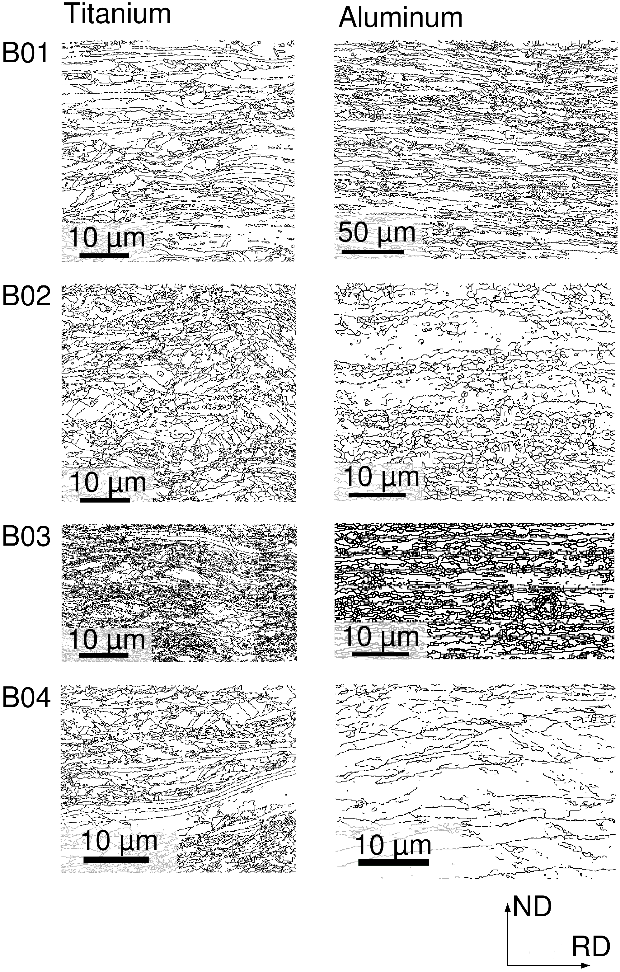
Figure 5 shows grain boundary maps for Al and Ti within a five-layered composite. EBSD images were taken within the Ti (left) and Al (right) layers at different deformation states. For the Ti layers within the five-layered composite, a quite similar behavior is observed for the deformed Ti, i.e., a reduction of the grain size with increasing number of DSR passes (compare to Figure 3). In contrast to this, the grain size observed within the aluminum layers also decreases with increasing shear deformation, which has not been observed for the equivalently deformed Al (compare Figure 1). However, the grain size within the Al layers is still larger with no shear deformation being applied when compared to the five-layered composite which has been deformed by DSR up to an equivalent strain. This difference between the conventionally rolled and differentially speed rolled five-layered composite is less pronounced for the Ti layers.
Figure 5. Grain boundary maps (i.e., boundaries with a misorientation angle of 15 degrees and above) for Al and Ti being co-deformed by ARB within a five-layer stack and subsequent DSR. B01: one rolling pass, speed ratio: 1:1; B02: one rolling pass, speed ratio: 1:5; B03: four rolling passes, speed ratio: 1:1; B04: conventional rolling with three rolling passes.
Metals 06 00031 g005
Figure 6a,b show the quantitative analysis of the grain sizes. In contrast to the findings of the pure metals, the present analysis shows a decreasing grain size with increasing shear deformation. This situation is independent on the weighting method. However, the total reduction of the grain size is rather small.
Figure 6. (a) Grain size within the Ti and Al layers with different weighting methods being applied: grain area with increasing speed ratio, i.e., amount of shear and (b) evolution of the grain size with increasing number of rolling passes (DSR) with a constant speed ratio of 1:1.
Metals 06 00031 g006
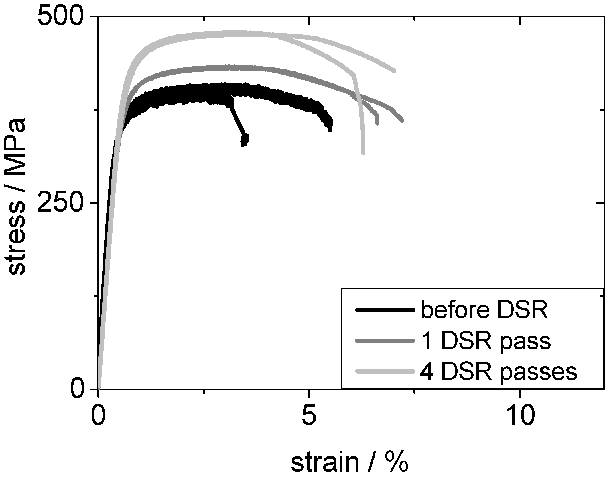
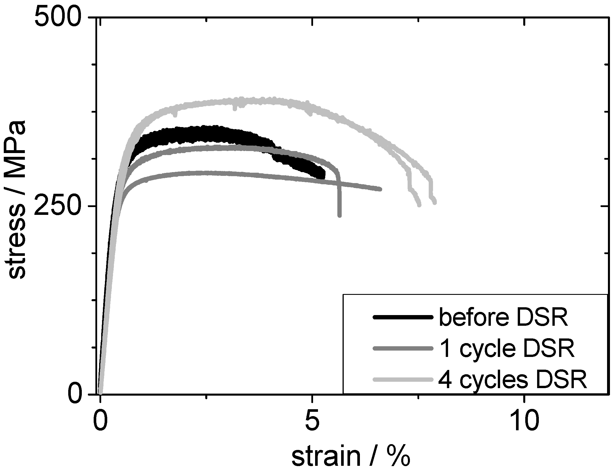
The five-layered composite has been generated by roll bonding with a total thickness reduction of 50%, which already imposes a high degree of deformation and causes a significant reduction in ductility when compared to the pure metals. The engineering stress-strain curves of the five-layered composite are shown in Figure 7 and should be compared to those of the pure metals (Figure 4). The large plastic strain at fracture which is observed for pure metals cannot be obtained in the multi-layered sheet. On the other hand, ARB strain hardens the composite and, in consequence, a yield strength of 320 MPa and an ultimate tensile strength of 403 MPa are observed for the five-layered composite. These strength values can be further increased by DSR, whereby a larger accumulated shear deformation by multiple DSR passes further increases the tensile strength.
Figure 7. Engineering tensile stress-strain curves of five-layered Ti/Al composites after ARB and further processing by DSR with a speed ratio of 1:1: with one and four DSR passes, respectively. Results for two samples in each condition are shown in order to illustrate the occurring variations.
Metals 06 00031 g007
A reduction of fracture strain which is generally observed with strength increase is not observed after processing by DSR. The ductility is even enhanced by DSR.
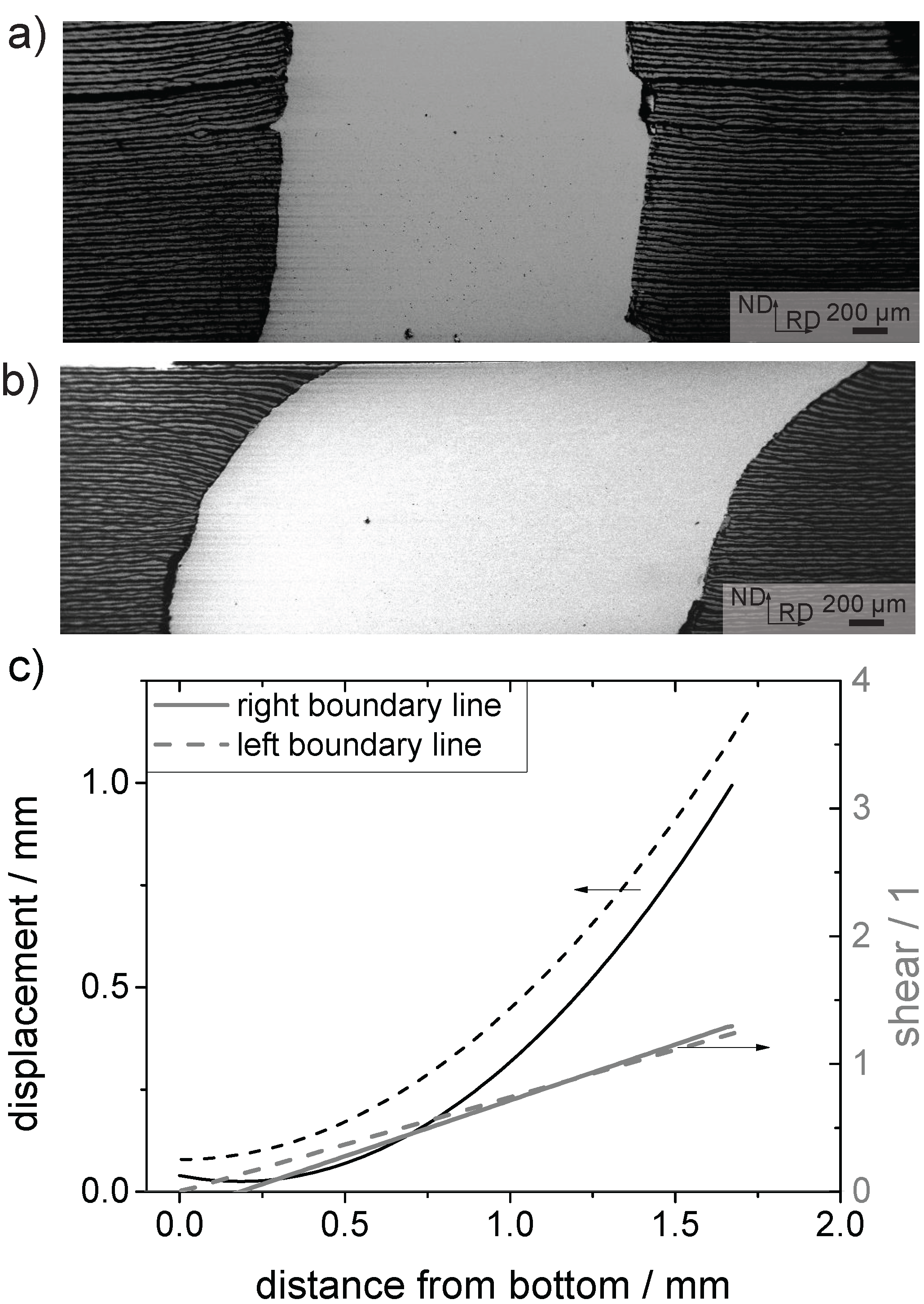
In the following, the question of how the accumulatively roll bonded Ti/Al multi-layered sheets react on DSR is addressed, i.e., on the superimposed shear. In order to visualize the shear being incorporated into the composites by DSR, a Cu-pin is utilized. This pin has been put into a drilled hole in a 160-layered Ti/Al composite sheet. The Cu is in a recrystallized state and, therefore, it deforms at lower stress than the composite and even its individual layers. Therefore, the shear strain applied can be easily obtained from the interface between the Cu pin and the composite. For this purpose, longitudinal cross-sectional cuts were prepared by standard metallographic procedures aiming at imaging the largest cross section of the Cu-pin. 
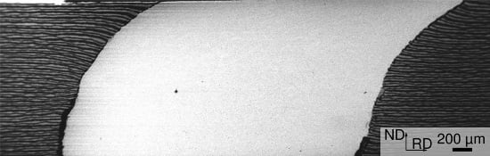
Figure 8 shows such cross-sectional cuts of the Cu-pin (bright grey) embedded within a 160-layered composite being prepared by ARB and (i) further conventionally rolled as well as (ii) further processed by DSR with a speed ratio of 1.1. Both composites were deformed by three rolling passes, incorporating a total strain of 0.62.
Figure 8. Shear deformation imaged by a Cu-pin inserted into a 160-layered Ti/Al composite. This Cu-pin shows no shearing in the case of conventional rolling (a); whereas DSR yields considerable shear (b); The left (dotted lines) and right (straight lines) boundaries between the Cu-pin and the Ti/Al-composite have been used to evaluate the relative position of the material as shown in the right chart (c). The grey lines represent the calculated amount of shear deformation.
Metals 06 00031 g008
Figure 8a,b reveal the shear deformation incorporated during DSR. The shear within the pin can be addressed to DSR, as no shearing of the Cu-pin is observed for the conventionally rolled 160-layered composite. The amount of shear has been evaluated from the curvature of the interfaces between the Cu-pin and the composite. Figure 8c shows the displacement of the Cu-pin relative to the vertical projection of the lowest position of the interface as a function of the distance from the bottom of the sheet. This evaluation has been performed for the left as well as the right interface in order to increase the accuracy. The effective amount of shear deformation has been calculated upon the displacement. The corresponding shear is shown in Figure 8c.
Assuming that the Cu-pin correctly reflects the amount of shear deformation and taking into account that the interfaces within the 160-layered composite do not fail during DSR, it can be concluded that the composite is also subjected to the same amount of shear deformation.
Figure 9 and Figure 10 show SEM micrographs of the microstructure of the composites processed by conventional rolling and DSR, respectively. Each of these images contain inserts showing grain boundary maps as obtained from EBSD measurements. In the case of the conventionally rolled 160-layered composite, the grain boundary maps are independent of the position at which they were taken.
Figure 9. SEM micrograph showing the microstructure of a 160-layered Ti/Al composite obtained from six ARB cycles and subsequent conventional rolling (three passes). The inserts show grain boundary maps that have been evaluated from EBSD measurements at the depicted positions. Lines indicate high angle grain boundaries including twin boundaries.
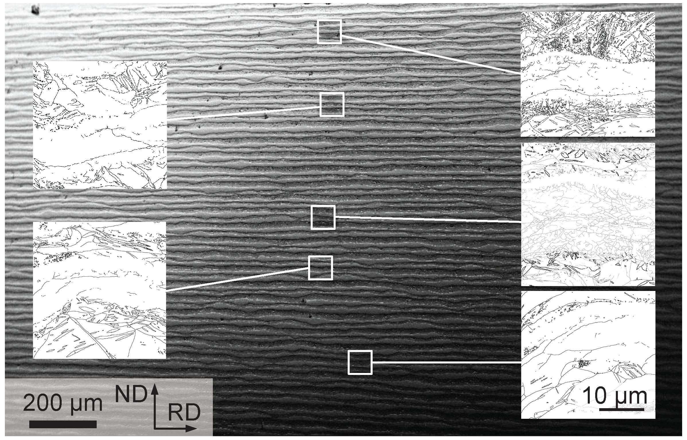
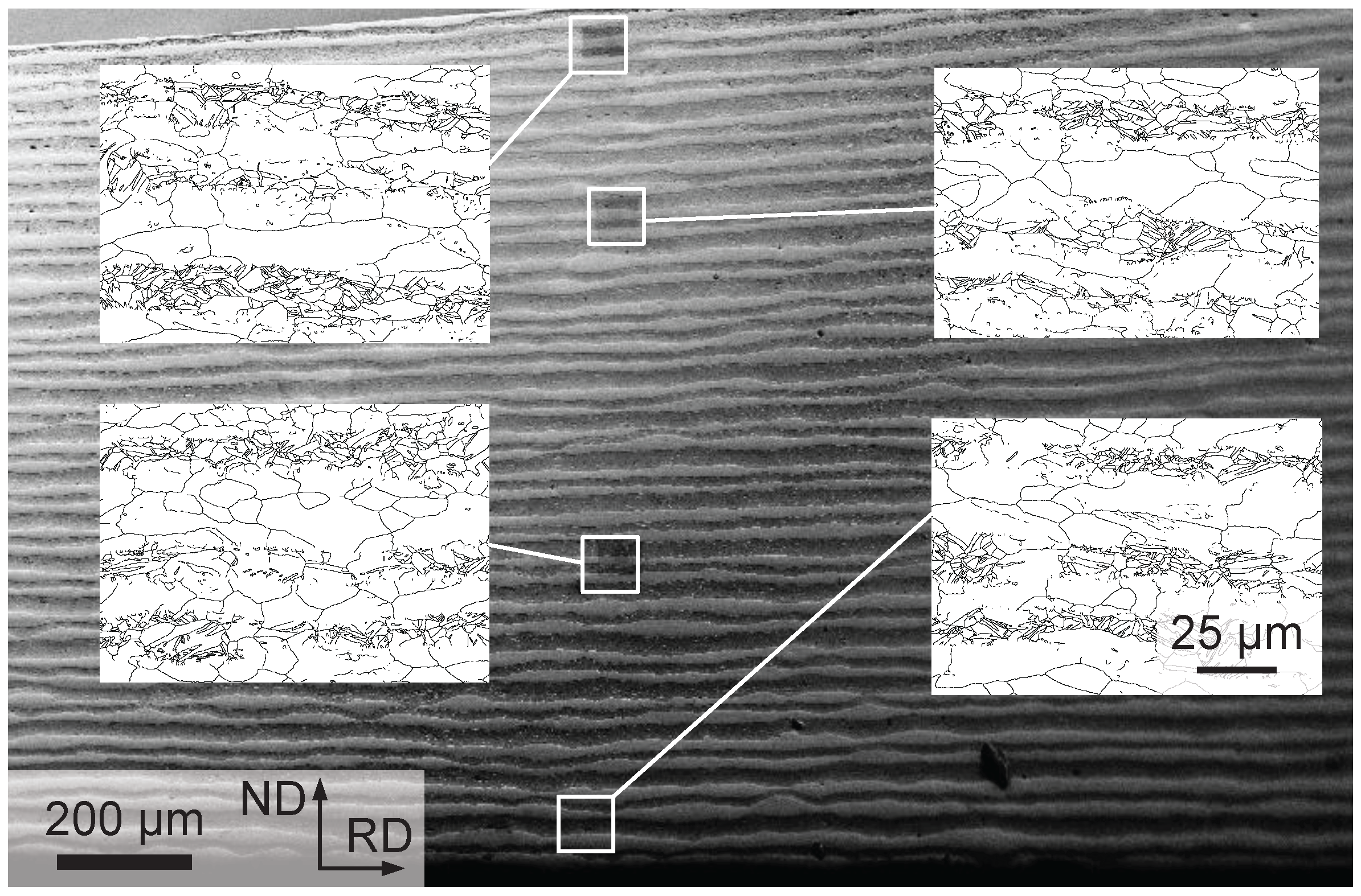
Metals 06 00031 g009
Figure 10. SEM micrograph showing the microstructure of a 160-layered Ti/Al composite obtained from six ARB cycles and subsequent differential speed rolling (three passes). The inserts show grain boundary maps at positions depicted. Lines indicate high angle grain boundaries including twin boundaries.
Metals 06 00031 g010
The situation is considerably different for the case of the 160-layered composite being processed by DSR. As this composite is subjected to an additional shear deformation, which increases with the distance from the lower roll (see Figure 8), a variation in the microstructure across the thickness of the sheets is observed. The macroscopic view of the sample shows the same features as in the case of the conventionally rolled 160-layered composite, i.e., continuous layers, some of them necked, but none failed, and no detachment of the layers occurred. The grain boundary maps show that the grain size shrinks with increasing shearing strain (in Figure 10 from bottom to top). It is noteworthy to mention that no intermetallic phase was detected by means of SEM within any cross section under investigation.
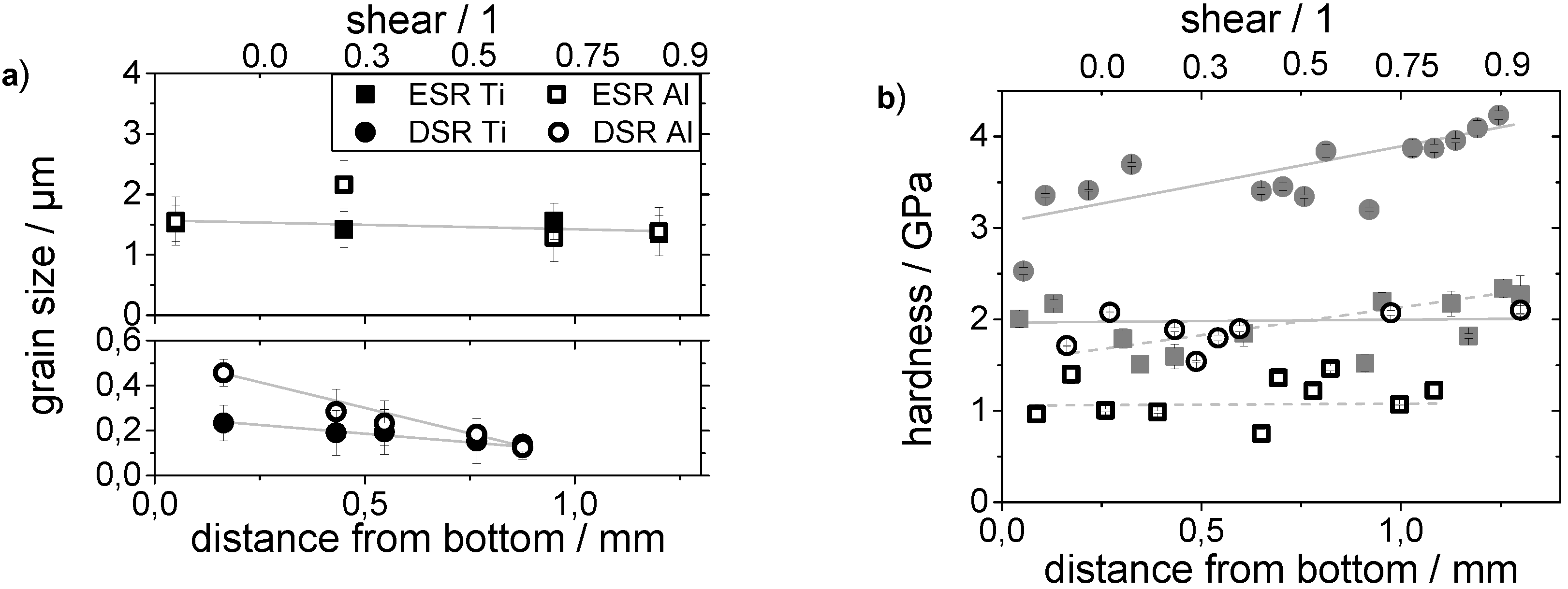
In order to quantitatively assess these images, the grain size has been evaluated upon the grain boundary maps. The corresponding mean grain sizes for the Ti and Al layers are shown for the conventionally rolled 160-layered composites as well as for the composites processed by DSR in Figure 11. The data has been evaluated upon the regions as depicted in Figure 9 and Figure 10. Figure 11b shows the hardness of the phases in both conditions.
Figure 11. Grain size (a) and hardness (b) of a 160-layered Ti/Al composite subjected to three passes of conventional rolling (ESR) or differential speed rolling (DSR). The values are taken along the thickness of the sheet and, thus, reflect the amount of shear introduced into the samples.
Metals 06 00031 g011
As already mentioned, when qualitatively discussing the grain boundary maps, the grain size shows no variation along the sheet thickness for the conventionally rolled composite. The Ti and Al grain sizes are about the same. As the composite is homogeneously strengthened by work-, phase- and grain-boundary hardening, it is not surprising that the hardness values are constant across the sample thickness.
This situation is different for the samples processed by DSR. The additionally introduced shear deformation yields a significant grain refinement. As the shear strain varies across the thickness of the sheet, the contribution of the Hall-Petch type hardening also differs. Indeed, the hardness increases with shear deformation as the grains undergo refinement. This is observed for the Ti as well as Al layers.
Up to here, the discussion regarding the effect of DSR on multi-layered Ti/Al composites was restricted to the speed ratio of 1.1. In the following, the effect of increasing speed ratio will be illustrated. 
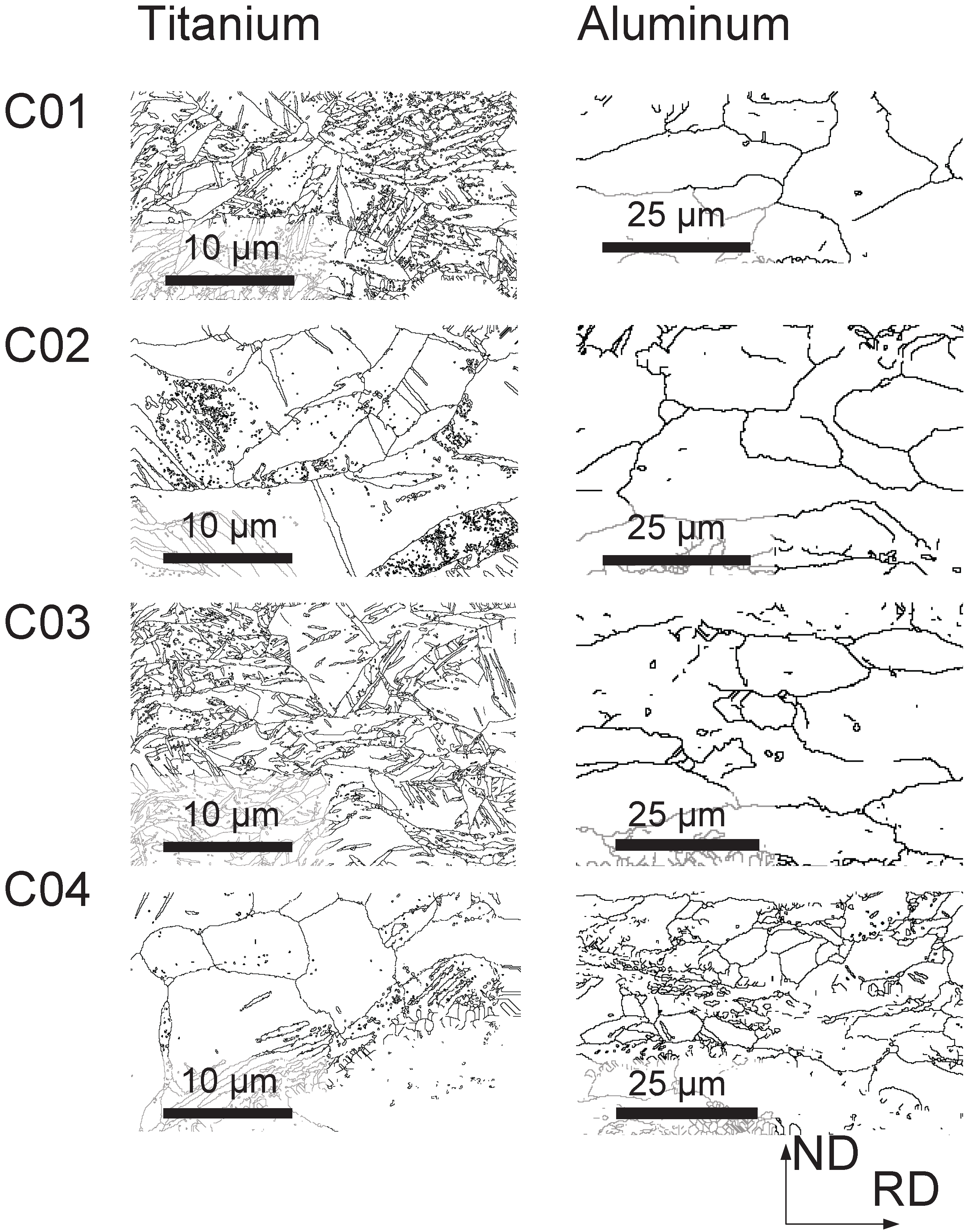
Figure 12 shows the effect of different rolling speed ratios on the microstructure of Ti and Al, respectively.
Figure 12. Grain boundary maps (i.e., boundaries with a misorientation angle of 15 and above) of the Ti (left) and Al (right) layers within a 160-layered Ti/Al composite sheet. The sheets are being deformed by rolling with one (C01) and three (C02-04) rolling passes. The speed ratio amounts to 1 (C01 and C02), 1:1 (C03) and 1:5 (C04), respectively.
Metals 06 00031 g012
As previously mentioned, the Al and Ti layers have a widely spread grain size distribution. Figure 13 shows the grain size within the Al and Ti layers evaluated upon the grain boundary maps shown in Figure 12. The effect of conventional rolling with up to three rolling passes on the grain size is not significant.
The smaller Al grains show a nearly constant grain size with increasing rolling shear, whereas the larger grains show a significant decrease in grain size. Both mean values come closer with increasing shear deformation. This is not observed for the grains within the Ti layers. Both values remain nearly constant. In addition, there is a significant change in the grain statistics. With increasing shear deformation, the number of small grains within the Al layers increases.
Figure 13. Grain size within the Al and Ti layers of a 160-layered Ti/Al composite sheet prepared by six ARB cycles and with three additional DSR passes with a speed ratio of up to 1:5. Gray colored data points correspond to samples being conventionally rolled up to the same shear strain.
Metals 06 00031 g013
The mechanical properties of the composite are affected by the microstructure. Figure 14 shows the engineering stress-strain curves of the 160-layered Ti/Al composite as well as the curves of composites being additionally deformed by DSR. One DSR pass decreases both UTS and yield strength but increases the strain to failure. However, the application of three further DSR passes increases the UTS and yield strength but also further increases the ductility.
Figure 14. Engineering tensile stress-strain curves of 160-layered Ti/Al composite sheets as well as those with subsequent DSR being applied with a speed ratio of 1.1. Results are shown for one and four DSR passes. Results for two samples in each condition are shown in order to illustrate the occurring variations.
Metals 06 00031 g014
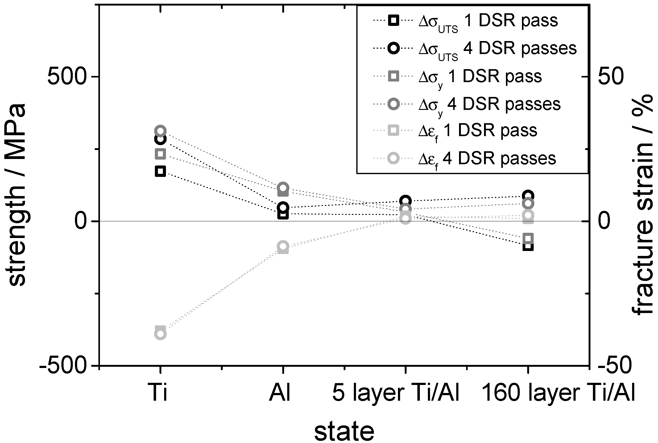
Figure 15 compares the development of the mechanical properties of all sheets examined. The influence of DSR is most remarkable in case of Ti sheets. The UTS increases from 200 MPa to 350 MPa after the first DSR cycle and to about 450 MPa after the fourth DSR cycle. At the same time, the elongation to failure decreases from 46% to 7%. The influence of DSR on Al follows the same tendency: UTS increases from 230 MPa to 280 MPa and later to 310 MPa while the elongation decreases from 12% to 3.8%. In the composite sheets, both the strength and the elongation to failure increase when the composite is deformed by DSR. However, this is only visible after four DSR passes. Whereas the UTS and strain to failure are nearly independent of the number of DSR passes for the five-layered composite, the 160-layered composite shows an increase for a higher number of DSR passes, only. Both values even show a decrease after the first DSR pass when compared to the initial state. This hints at the fact that friction between the layers plays a significant role with respect to the deformation behavior and especially with respect to the observed elongation to failure. The tensile test samples from the 160-layered Ti/Al composite shows noticeable sliding of the layers at the Ti-Al interfaces.
Figure 15. Effect of DSR on the mechanical properties. The chart shows the change of the ultimate tensile strength, yield strength and strain to failure for pure Al and Ti as well as for five-layered and 160-layered Ti/Al composite sheets before and after DSR.
Metals 06 00031 g015

4. Conclusions

Differential speed rolling of Ti/Al composite sheets leads to an increased ductility due to an improved macroscopic shear strain. The different layers of a five-layered composite sheet prepared by a single ARB cycle slide along the phase boundary during DSR. In contrast, a 160-layered composite prepared by six ARB cycles reveals shear deformation of the individual layers. This shear deformation shows a gradient in the direction of sample thickness and increases from the layer next to the slower roll to that next to the faster roll. Furthermore, the shear deformation causes hardening and grain refinement and, consequently, gradients in grain size and hardness. Table 1 qualitatively summarizes the evolution of the grain size during DSR of single material sheets as well as five- and 160-layered composites. An increase in the speed ratio affects the grain size differently compared to an increase in the number of DSR passes. Except for separately rolled Al, the grain size decreases with increasing speed difference. During further DSR passes, the grain size remains constant or even increases. In case of the five-layered composite, the grains further refine when DSR passes are repeated.
The application of DSR facilitates both an increase in UTS and ductility while the laminated structure is retained. The tensile strength increases with the number of DSR passes up to 464 MPa, and the elongation to failure rises to 6.8% for the five-layered composite. Strengthening is caused by grain refinement, strain hardening and an increase of bonding strength between the layers.
Table 1. Qualitative evolution of the grain size during DSR responding to increasing speed ratio and increasing DSR pass number. (A) single material sheets; (B) five-layered composite sheets; (C) 160-layered composite sheets.
SeriesMaterialEffect ofEffect ofEffect ofEffect of
Speed RatioSpeed RatioPass NumberPass Number
Small GrainsLarge GrainsSmall GrainsLarge Grains
AAl
ATi
BAl
BTi
CAl
CTi

Acknowledgments

This work has been supported by the European Union and the Free State of Saxonia in the framework of the European Centre for Emerging Materials and Processes (ECEMP), contract No. 13795/2379. The authors gratefully acknowledge support with the hardness measurements from Verena Maier and Mathias Göken (University Nürnberg-Erlangen) as well as Kristina Eichhorn and Konrad Schneider (Leibniz Institute for Polymer Research Dresden).

Author Contributions

Jan Romberg and Jens Freudenberger designed the experiments, collected and interpreted the data, wrote and edited the paper, and contributed to all activities. Juliane Scharnweber and Andy Eschke contributed to electron microscopy, including sample preparation, image and diffraction collection; together with Carl-Georg Oertel, they analysed the results and fostered their interpretation. Hiroyuki Watanabe performed the differential speed rolling experiments and contributed to the interpretation of the results. Hansjörg Klauß performed the tensile tests. Uta Kühn, Werner Skrotzki, Jürgen Eckert and Ludwig Schultz directed the research and contributed to the discussion and interpretation of the results.

Conflicts of Interest

The authors declare no conflict of interest.

References

  1. Romberg, J.; Freudenberger, J.; Bauder, H.; Plattner, G.; Krug, H.; Scharnweber, J.; Eschke, A.; Kühn, U.; Klauß, H.; Oertel, C.G.; et al. Ti/Al Multilayered Sheets: Accumulative Roll Bonding (part A). Metals 2016, 6, 30. [Google Scholar]
  2. Kim, W.; Hwang, B.; Lee, M.; Park, Y. Effect of speed-ratio on microstructure, and mechanical properties of Mg-3Al-1Zn alloy, in differential speed rolling. J. Alloys Compd. 2011, 509, 8510–8517. [Google Scholar] [CrossRef]
  3. Ko, Y.G. Microstructure evolution and mechanical properties of severely deformed Al alloy processed by differential speed rolling. J. Alloys Compd. 2012, 536, S122–S125. [Google Scholar]
  4. Chang, L.; Cho, J.; Kang, S. Microstructure and mechanical properties of AM31 magnesium alloys processed by differential speed rolling. J. Mater. Process. Technol. 2011, 211, 1527–1533. [Google Scholar] [CrossRef]
  5. Watanabe, H.; Mukai, T.; Ishikawa, K. Effect of temperature of differential speed rolling on room temperature mechanical properties and texture in an AZ31 magnesium alloy. J. Mater. Process. Technol. 2007, 182, 644–647. [Google Scholar] [CrossRef]
  6. Huang, X.; Suzuki, K.; Chino, Y. Improvement of stretch formability of pure titanium sheet by differential speed rolling. Scr. Mater. 2010, 63, 473–476. [Google Scholar] [CrossRef]
  7. Kim, W.; Lee, H.; Yoo, S.; Park, Y. Texture and mechanical properties of ultrafine-grained Mg-3Al-1Zn alloy sheets prepared by high-ratio differential speed rolling. Mater. Sci. Eng. A 2011, 528, 874–879. [Google Scholar] [CrossRef]
  8. Lee, S.; Saito, Y.; Tsuji, N.; Utsunomiya, H.; Sakai, T. Role of shear strain in ultragrain refinement by accumulative roll-bonding ARB process. Scr. Mater. 2002, 46, 281–285. [Google Scholar] [CrossRef]
  9. Sakai, T.; Saito, Y.; Hirrano, K.; Kato, K. Deformation and Recrystallization Behavior of Low Carbon Steel in High Speed Hot Rolling. Trans. Iron Steel Inst. Jpn. 1988, 28, 1028–1035. [Google Scholar] [CrossRef]
  10. Kim, W.; Wang, J.; Choi, S.; Choi, H.; Sohn, H. Synthesis of ultra high strength Al-Mg-Si alloy sheets by differential speed rolling. Mater. Sci. Eng. A 2009, 520, 23–28. [Google Scholar] [CrossRef]
  11. Ko, Y.G.; Lee, J.S. Microstructure evolution and mechanical properties of ultrafine grained IF steel via multipass differential speed rolling. Mater. Sci. Technol. 2013, 29, 553–558. [Google Scholar] [CrossRef]
  12. Suharto, J.; Ko, Y.G. Annealing behavior of severely deformed IF steel via the differential speed rolling method. Mater. Sci. Eng. A 2012, 558, 90–94. [Google Scholar] [CrossRef]
  13. Iro, A.; Zhou, Z.; Utsunomiya, H.; Sakai, T. Reduction in Planar Anisotropy of Pure Niobium Sheet by Asymmetric Rolling. Tetsu Hagane J. Iron Steel Inst. Jpn. 2011, 97, 572–577. [Google Scholar]
  14. Jiang, J.; Ding, Y.; Zuo, F.; Shan, A. Mechanical properties and microstructures of ultrafine-grained pure aluminum by asymmetric rolling. Scr. Mater. 2009, 60, 905–908. [Google Scholar] [CrossRef]
  15. Polkowski, W.; Jozwik, P.; Polanski, M.; Bojar, Z. Microstructure and texture evolution of copper processed by differential speed rolling with various speed asymmetry coefficient. Mater. Sci. Eng. A 2013, 564, 289–297. [Google Scholar] [CrossRef]
  16. Cho, J.H.; Kim, H.W.; Kang, S.B.; Han, T.S. Bending behavior, and evolution of texture and microstructure during differential speed warm rolling of AZ31B magnesium alloys. Acta Mater. 2011, 59, 5638–5651. [Google Scholar] [CrossRef]
  17. Chang, L.; Kang, S.; Cho, J. Influence of strain path on the microstructure evolution and mechanical properties in AM31 magnesium alloy sheets processed by differential speed rolling. Mater. Des. 2013, 44, 144–148. [Google Scholar] [CrossRef]
  18. Lee, J.; Konno, T.; Jeong, H. Grain refinement and texture evolution in AZ31 Mg alloys sheet processed by differential speed rollingloo. Mater. Sci. Eng. B 2009, 161, 166–169. [Google Scholar] [CrossRef]
  19. Kim, W.; Yoo, S.; Jeong, H.; Kim, D.; Choe, B.; Lee, J. Effect of the speed ratio on grain refinement and texture development in pure Ti during differential speed rolling. Scr. Mater. 2011, 64, 49–52. [Google Scholar] [CrossRef]
  20. Kim, W.; Yoo, S.; Lee, J. Microstructure and mechanical properties of pure Ti processed by high-ratio differential speed rolling at room temperature. Scr. Mater. 2010, 62, 451–454. [Google Scholar] [CrossRef]
  21. Terada, D.; Inoue, S.; Tsuji, N. Microstructure and mechanical properties of commercial purity titanium severely deformed by ARB process. J. Mater. Sci. 2007, 42, 1673–1681. [Google Scholar] [CrossRef]
  22. Ng, H.; Przybilla, T.; Schmidt, C.; Lapovok, R.; Orlov, D.; Höppel, H.W.; Göken, M. Asymmetric accumulative roll bonding of aluminium-titanium composite sheets. Mater. Sci. Eng. A 2013, 576, 306–315. [Google Scholar] [CrossRef]
  23. Romberg, J.; Freudenberger, J.; Scharnweber, J.; Gaitzsch, U.; Marr, T.; Eschke, A.; Kühn, U.; Oertel, C.G.; Okulov, I.; Petters, R.; et al. Metallographic Preparation of Aluminium-Titanium Composites. Pract. Metallogr. 2013, 50, 739–753. [Google Scholar] [CrossRef]
  24. Hall, E. The deformation and ageing of mild steel: III. Discussion and results. Proc. Phys. Soc. Sect. B 1951, 64, 747–753. [Google Scholar] [CrossRef]
  25. Petch, N. The cleavage strength of polycrystalls. J. Iron Steel Inst. 1953, 174, 25–28. [Google Scholar]

