Article

Double-Flush Riveting for Hybrid Busbar Assembly

by
Rui F. V. Sampaio
1,
João P. M. Pragana
1,*,
Miguel P. Figueiredo
1,
Ivo M. F. Bragança
2,
Carlos M. A. Silva
1 and
Paulo A. F. Martins
1
1
IDMEC, Instituto Superior Técnico, Universidade de Lisboa, 1049-001 Lisboa, Portugal
2
CIMOSM, Instituto Superior de Engenharia de Lisboa, Instituto Politécnico de Lisboa, 1549-020 Lisboa, Portugal
*
Author to whom correspondence should be addressed.
Metals 2025, 15(5), 521; https://doi.org/10.3390/met15050521
Submission received: 2 April 2025 / Revised: 29 April 2025 / Accepted: 3 May 2025 / Published: 5 May 2025
(This article belongs to the Special Issue Numerical Modelling of Metal-Forming Processes)

Abstract

:
This paper explores a novel double-flush riveting process for assembling hybrid busbars made from aluminum and copper sheets. The process involves drilling and forging countersunk holes with controlled geometry in both materials followed by compression of cylindrical rivets into the holes to create strong, form- and force-closed mechanical joints. Experimental and numerical analyses are combined to examine material flow, quantify the required forces, and assess the structural integrity of the joints through destructive testing. Additionally, the electrical resistance of these novel joints is evaluated and compared with that of ideal and conventional fastened hybrid busbar joints in order to assess their performance and reliability in real-world electrical service conditions. The results indicate that the novel double-flush riveting process is a viable alternative to other conventional joining processes, such as fastening, delivering good structural integrity and enhanced electrical conductivity for hybrid busbar applications.

1. Introduction

Joining technologies play a critical role in assembling multiple sheet metal components into single functional units, either with or without the use of external elements, heat, or pressure.
Among the different types of sheet metal assemblies, lap joints, where two sheets overlap, are widely used across numerous applications for their practical effectiveness. Lap joints can be created through welding, brazing, soldering, bonding, or mechanical joining technologies, each having its own advantages and limitations [1], particularly when it comes to joining dissimilar materials, such as aluminum and copper (Figure 1).
While commonly used, welding often leads to metallurgical changes, residual stresses, and distortions resulting from thermal cycling, which can significantly limit its effectiveness and applicability to dissimilar material combinations [2]. Brazing and soldering offer some relief from these issues by utilizing molten filler materials, but they compromise joint strength and require precise surface preparation.
Bonding provides a non-metallic alternative that avoids thermal effects while enabling versatile connections across various materials. However, adhesive joints require extended curing times, careful surface treatment, and environmental compliance considerations [3].
Mechanical joining, including fastening and joining by plastic deformation, offers alternative processes that eliminate the use of heat and hazardous substances. Fastening processes, such as bolting and riveting (Figure 1), are renowned for their flexibility and robustness, with riveting being particularly advantageous for creating vibration-resistant, high-strength joints. Still, they are limited by the inherent material protrusions (bolt and rivet heads) above and below the lap joint surfaces and by the impact of unintentional loosening in the case of bolted joints [4].
Joining by plastic deformation processes like self-pierce riveting [5] and clinching [6] (Figure 1) allows for room-temperature joining without causing metallurgical degradation, but they impose restrictions on material thickness and formability, as well as on the final shape of the lap joint surfaces [7].
Flush riveting (also known as ‘countersunk riveting’), as shown in Figure 1, is a joining by plastic deformation process that creates low-profile joints by embedding the riveting head within the surface of the sheet [8]. This method is commonly employed in applications requiring a smooth surface finish from one side of the lap joints, such as aerospace structures [9]. However, unlike the other processes previously discussed, flush riveting has yet not been applied in the assembly of busbars. Recent applications of flush riveting primarily focus on the aerospace industry, where they join both metallic and composite sheets using either metallic or composite rivets. Recent applications of flush riveting primarily focus on the aerospace industry, where the process is used to join both metallic [10] and composite sheets using either metallic [11,12] or composite rivets [13].
This paper emphasizes this critical oversight, as busbars are essential components of modern electric power distribution systems [14], and revisits the original double-flush riveting process, recently proposed by Sampaio et al. [15], for assembling structural joints made from aluminum sheets (Figure 2a). In fact, despite the ability of this process, which combines blanking and compression operations to create form- and force-closed mechanical joints and deliver flat surfaces on both sides of the joints, it has not yet been utilized for assembling hybrid busbars made from aluminum and copper sheets of varying thicknesses.
Three main reasons hinder the formation of reliable, form- and force-closed joints in hybrid busbars using the original double-flush riveting process [15]: (i) the inconsistencies in the morphology of the cut surfaces caused by punch wear during production, (ii) the inherent limitations of the tapered cut surface angle, also known as the ‘breakout angle’, typically falling below 15 degrees, and (iii) the challenges of assembling sheets of different thicknesses.
This paper introduces an innovative enhancement to the double-flush riveting process. The improvement involves using drilling and forging instead of punching to accurately shape countersunk holes in aluminum and copper sheets before compressing cylindrical rivets into these holes (Figure 2b). This enhancement effectively overcomes the above-mentioned limitations of the original double-flush riveting process, resulting in strong, form- and force-closed mechanical joints.
The work described in this paper examines material flow, quantifies the required forces, and evaluates the mechanical integrity of the hybrid busbar joints produced by the novel double-flush riveting process. It combines experimental analysis with finite element modeling and compares the electrical resistance of the new double-flushed hybrid busbars with that of both ideal and conventional fastened hybrid busbars to assess their performance in real-world electrical service conditions.
The innovative double-flush riveting technique applied to hybrid busbars, which combine aluminum and copper of varying thicknesses, effectively addresses the trade-offs between these two materials. Copper has very low electrical resistivity but a higher density, whereas aluminum has higher electrical resistivity, lower density, and a lower cost [16]. As a result, hybrid busbar systems are designed with increased aluminum sheet thicknesses to achieve electrical conductivity levels closer to those of the thinner copper sheets [17,18].
Numerical and experimental results prove that the novel double-flush riveting process creates high-performance lap joints with flat surfaces on both sides. Furthermore, it provides an effective, reliable, and electrically optimized alternative to conventional fastening procedures used in hybrid busbar applications.

2. Materials and Methods

2.1. Materials, Flow Curves, and Electrical Resistivity

The novel double-flush riveting process was validated by fabricating unit cells representing the hybrid busbar joints, as shown in Figure 3. Each cell was constructed using laminated C11000 electrolytic copper and AA6082-T6 aluminum sheets. The sheets were 100 mm in length and 50 mm in width, with thicknesses of 2 mm for copper and 5 mm for aluminum. Their cross-sectional area ratio S A l / S C u = 2.5 closely matches the theoretical ratio of 2.3, which is necessary to ensure equal electrical conductance in the copper and aluminum sheets [17].
The rivets were machined from C11000 electrolytic copper rods to fit the inner diameter of the hole and ensure complete filling of the double-countersunk geometry after compression to create a form-and force-closed mechanical joint.
The mechanical characterization of the aluminum and copper sheets was conducted using tensile testing on an Instron 4507 universal testing machine and stack compression tests on an Instron Satec 1200 hydraulic testing machine. Specimens were extracted from the sheets, and the tests were performed with a crosshead speed of 5 mm/s. Tensile tests were performed according to the ASTM standard E8/E8M [19], while stack compression tests followed the ASTM standard E9-89A [20] for compression testing (Figure 4a). These latter tests were necessary for determining the stress–strain response at higher strain values, similar to those encountered during joining by plastic deformation.
The mechanical characterization of the copper rod was performed using compression tests on specimens machined from the provided rod in the Instron Satec 1200 hydraulic testing machine, following ASTM standard E9-89A [20].
Figure 4a illustrates the experimental true stress vs. true strain curves, also known as ‘flow curves’, for the sheets and rivet materials obtained from the tensile and compression tests.
The relationship between electrical resistivity and temperature for aluminum and copper, shown in Figure 4b, was established by measuring the electrical resistance of the sheets at different service temperatures. These measurements were conducted using an experimental setup constructed by the authors that is schematically illustrated in Figure 4b and employed a four-point probe technique based on Ohm’s law [21].
The measurement of the voltage drop used two probes that were spaced apart and connected to a micro-ohmmeter, KoCoS PROMET R600, which supplied an electric current of 600 A for approximately 2 s. Additionally, an AC transformer (OFICEL 1.5 kVA) integrated into the setup was employed to preheat the specimens to a maximum temperature T m a x = 115 using the Joule heating effect. The voltage drop was measured during the cooling phase after the AC transformer was turned off, within the temperature range T = 105 to T = 20 , specified by the IEEE standard for metal-clad switchgears [22].
The results for the medium carbon steel used in fasteners were retrieved from the literature [23].
A Flir E86 infrared camera was used to monitor the temperature evolution at the center of the sheets. More details on the experimental apparatus and testing procedure can be found elsewhere [17].

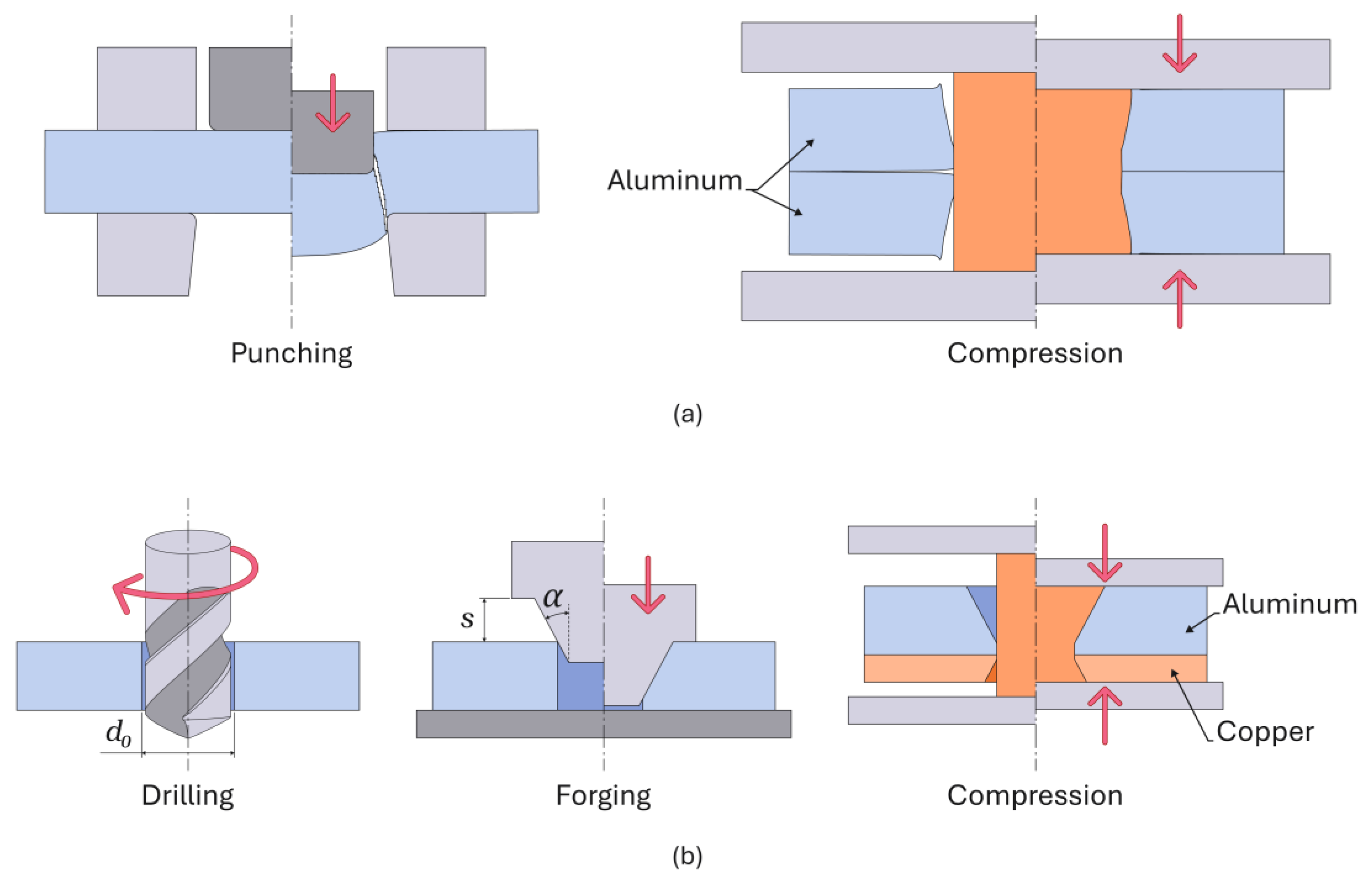
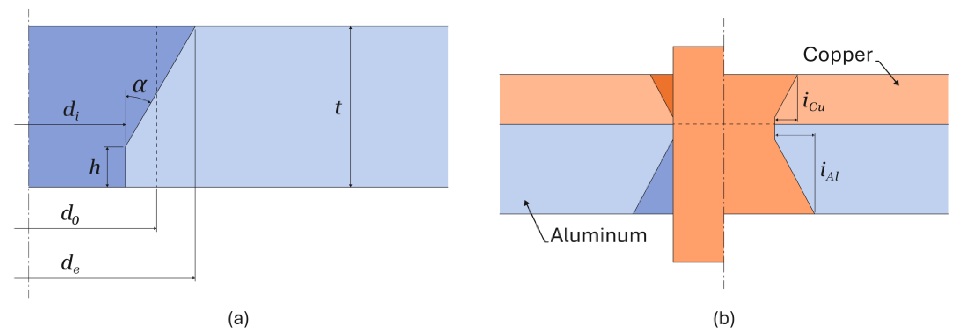
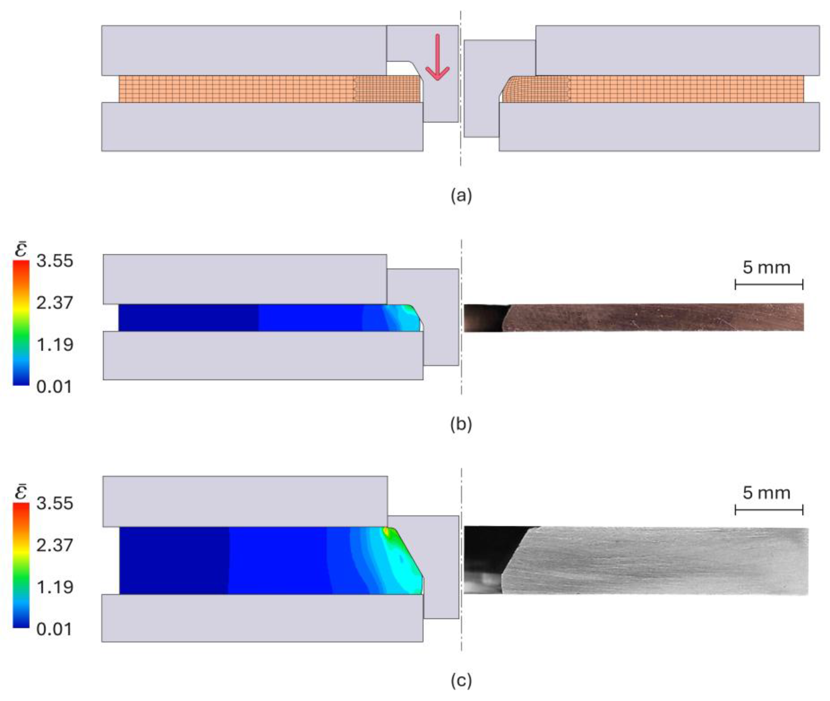
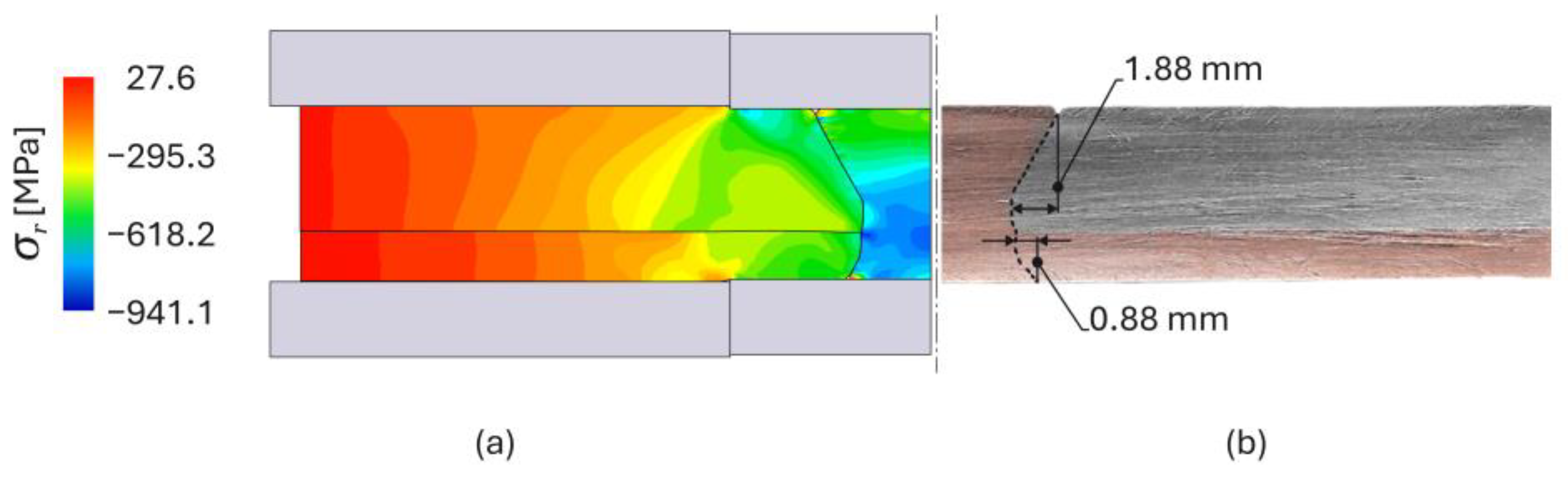
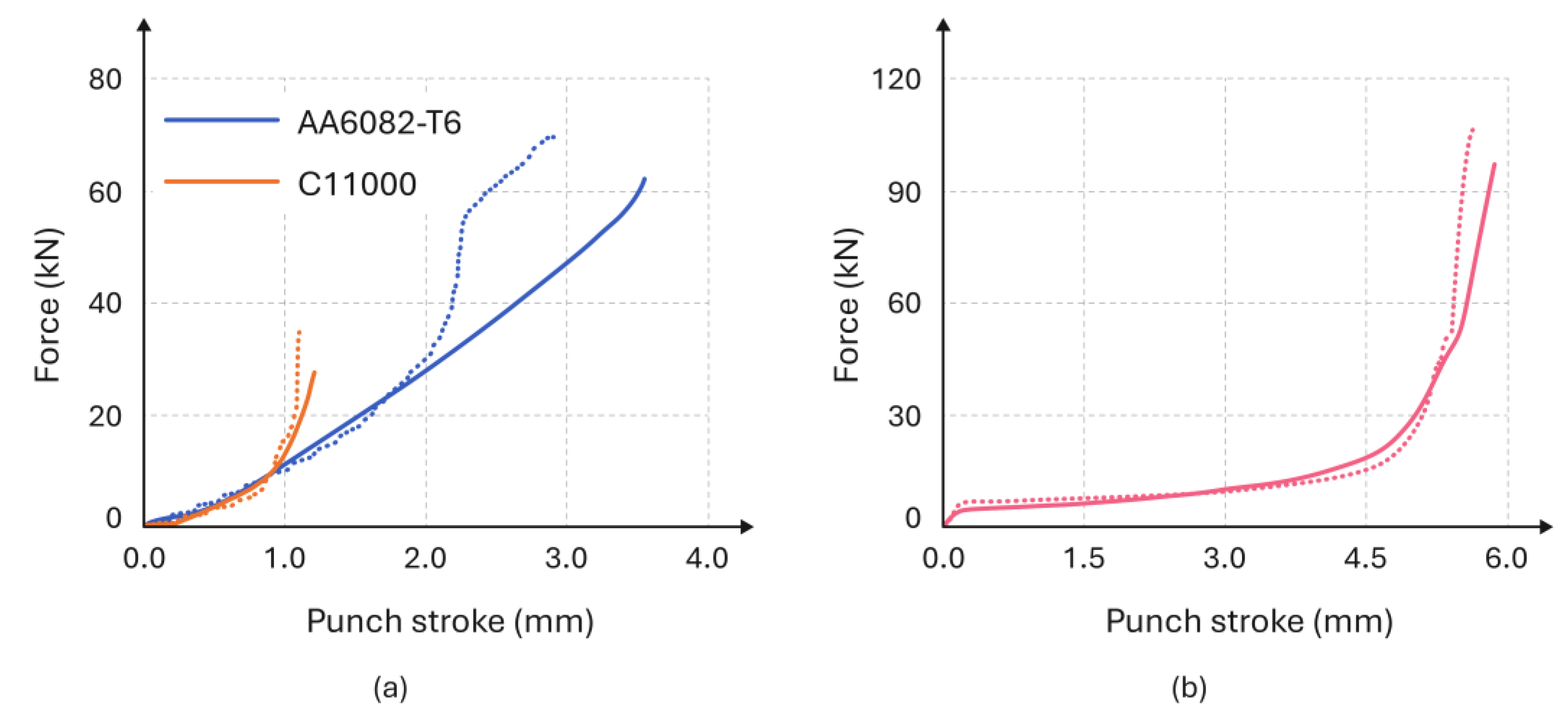
2.2. Double-Flush Riveting

In the first stage of the double-flush riveting (DFR) process, aluminum and copper sheets are drilled to create cylindrical holes with a diameter d 0 (refer to the dashed vertical line in Figure 5a). Then, one end of each hole in both sheets is forged to create countersunk holes with an inclination angle α = 30 ° and a specific inner diameter d i . The inclination angle α was selected from a previous investigation by the authors [24], which demonstrated that an angle of 30 ° creates greater interlocking while avoiding major distortion in the original hole and sheet geometries. Inclination angles above 30 ° tend to cause substantial radial displacement, which leads to an undesirable absence of rivet material as the diameter increases and the sheet bends.
The difference between the initial diameters of the drilled d 0 and forged d i holes is essential to account for material flow during the forging stage, and to ensure the required final inner diameter d i = 5 mm after forging, regardless of the sheet material or thickness, as shown in Figure 5b.
The cylindrical height h is set to be equal to 1/4 of the sheet thickness t , and given the angle of the forged hole (Figure 5) α = 30 ° , the external diameter d e of the countersunk hole can be calculated as follows:
d e = d i + 2 t h tan α = d i + 3 2 t
The initial drilled hole diameter d 0 can be determined by equating the volume of the hole before V 0 and after V f sheet forging through volume conservation. This results in the following expression:
V 0 = V f π d 0 2 4 t = π 12 t h d e 2 + d i 2 + d e d i + π d i 2 4 h  
By substituting Equation (1) into (2), one obtains the following expression for the initial diameter d 0 of the drilled cylindrical holes:
d 0 = d i 2 + 3 3 8 d i t + 3 16 t 2
One obtains initial hole diameter values d 0 C u = 5.68 mm and d 0 A l = 6.78 mm by applying equation (3) to the required experimental conditions of d i = 5 mm and t C u = 2 mm and t A l = 5 mm for the copper and aluminum sheets. However, drill bits with diameters of 5.5 mm and 6 mm were used to make the holes in the copper and aluminum sheets, respectively, and to ensure the existence of sufficient material to compensate for material flow by plastic deformation away from the hole axis, as will be seen in the section ‘Results and Discussion’.
Once the countersunk holes are forged, cylindrical copper rivets with a diameter of 5 mm are placed into the holes and compressed to create a form- and force-closed joint without protrusions. These rivets are manufactured with a height of 12 mm to ensure proper filling of the forged holes, and their position on the sheets (Figure 5b) guarantees that the side of the rivet on each sheet is enough to fill its respective hole and create the mechanical interlocking distance i = d e d i / 2 .
The sheets and rivets were forged at ambient temperature using the same hydraulic testing machine utilized for the stack compression tests, with a crosshead moving speed of 5 mm/s.

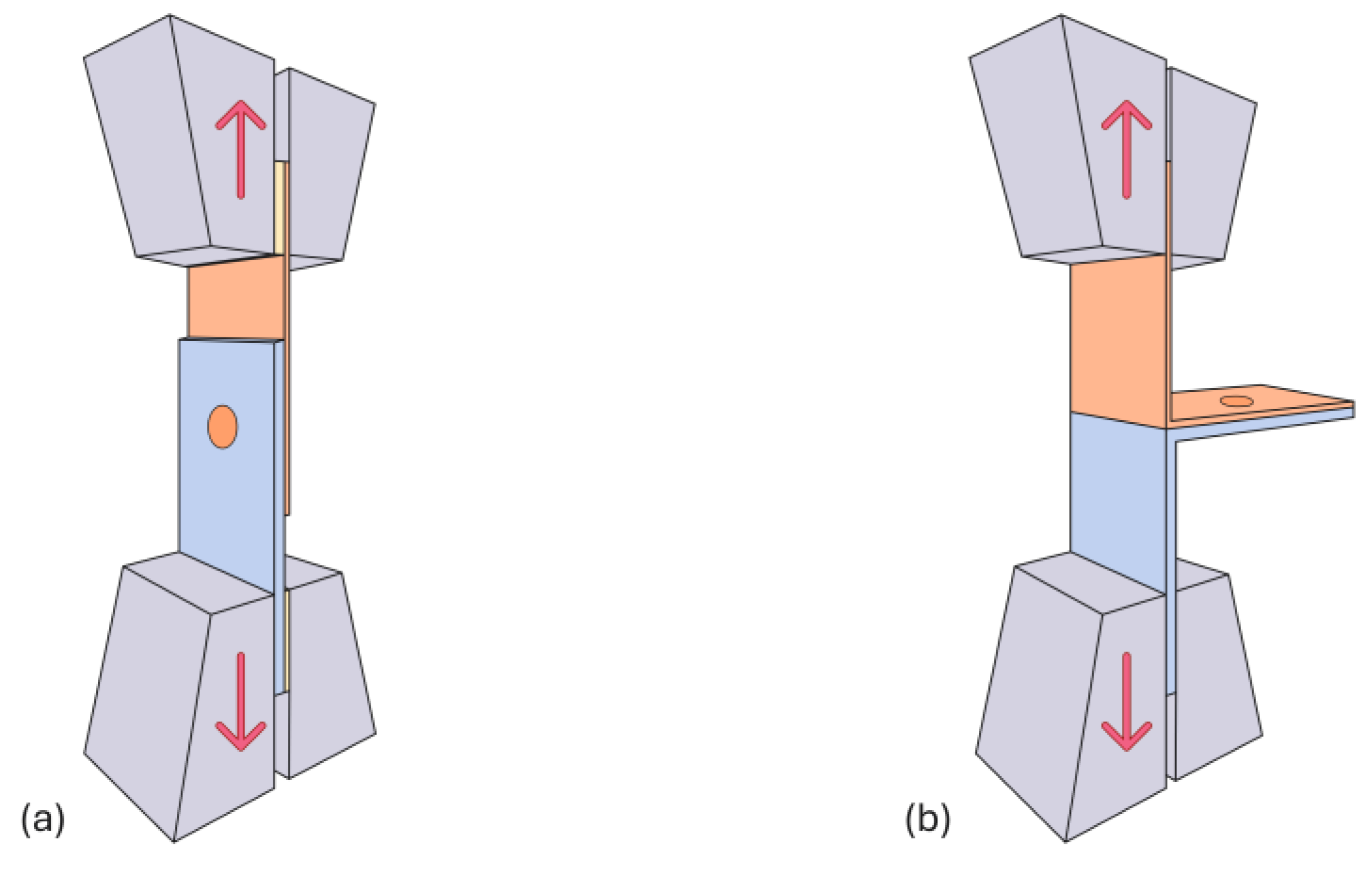
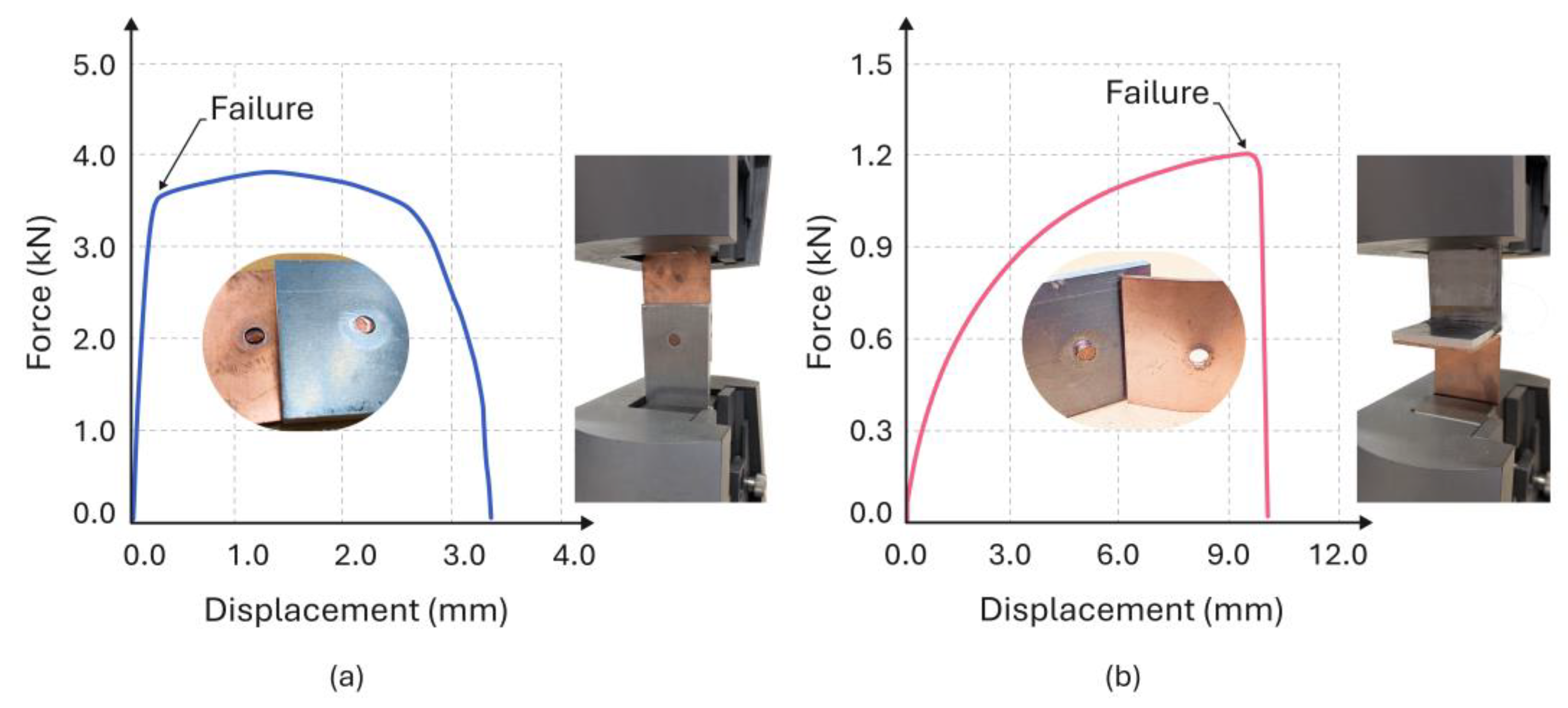
2.3. Electro-Mechanical Testing of the Double-Flush Riveted Joints

The mechanical reliability of the double-flush riveted joints was evaluated through destructive shear and peeling tests, as illustrated in Figure 6a,b. The tests were conducted at ambient temperature using the same universal testing machine that was used for material characterization, with a crosshead speed of 5 mm/s. The lap joints were prepared in accordance with the ISO Standard 14270 [25] for resistance spot welding, due to the lack of specific standards for double-flush riveted joints.
Additionally, the lap joints were subjected to thermo-electrical characterization tests. This procedure was the same as that used to establish the relationship between electrical resistivity and temperature for the aluminum and copper sheets, which can be seen in Figure 4b.
For statistical significance, a minimum of three joints were used in each test (destructive shear, destructive peeling, and thermo-electrical).

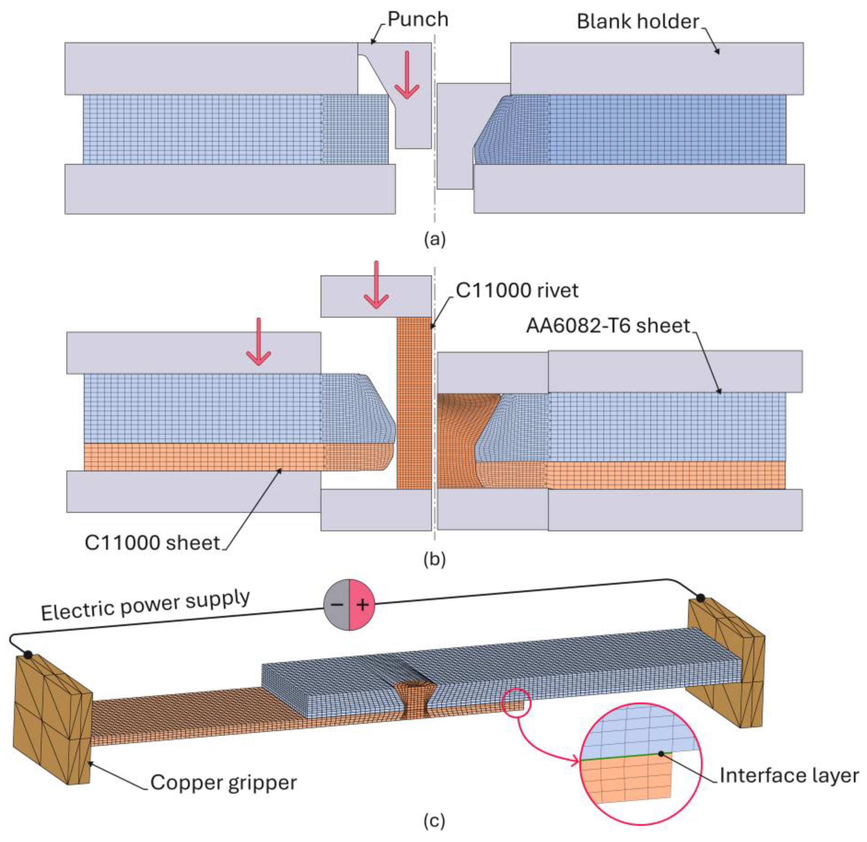
2.4. Finite Element Modeling

Double-flush riveting was simulated using the in-house finite element software i-form [26]. This program is based on the finite element flow formulation and employs a modified version of the weak form of the equilibrium equations σ i j / x j = 0 that effectively incorporates contact with friction between deformable and rigid bodies, as follows:
V σ i j δ D i j d V + V σ m δ D v d V S t t i δ u i d S + S f 0 u r τ f δ u r d S = 0
The formulation presented in (4) employs an ‘updated Eulerian approach’ based on a control volume V , and treating velocities u i as the primary unknown variables [27]. In this method, the geometry is fixed, and the velocities at specific points in space remain constant during each time step. Equilibrium is assessed through iterative procedures designed to minimize the residual force vector to within a specified tolerance. Following this, the geometry is updated according to an explicit time integration scheme based on the calculated velocities u i .
The first term in (4) utilizes the deviatoric Cauchy stress tensor σ i j and the rate of deformation tensor D i j and is directly related to the increment in plastic power. In contrast, the second term employs the hydrostatic stress σ m and volumetric rate of deformation D v , and is numerically handled by relaxing the incompressibility condition of the velocity field by setting a large positive number K (referred to as the ‘penalty’). The hydrostatic stress resulting from this procedure is determined as σ m = K / 2 D v .
The third term in (4) corresponds to the traction forces t i applied on the boundary S t , and the fourth term accounts for the frictional effects due to material sliding, with a relative velocity u r , along the contact interfaces S f . Friction is modeled by means of the law of constant friction, τ f = m k , where τ f is the friction shear stress, m is the friction factor, and k is the shear flow stress. Equation (4) is essentially a balance of virtual power, in which the internal power is balanced by the power exerted by external forces (traction forces, t i ) and friction effects τ f .
Figure 7 illustrates the typical axisymmetric finite element models used in the numerical simulation of sheet forging (shown in Figure 7a) and double-flush riveting (shown in Figure 7b), depicting both the beginning and end of each stage. In these simulations, the sheets and rivets were treated as deformable objects undergoing plastic deformation, with their cross-sections discretized by means of quadrilateral elements. The tools were considered rigid objects, and their contours were discretized using linear contact friction elements.
The thermo-electrical analysis focused on electrical resistance and current distribution in double-flush riveted joints at different busbar service temperatures. For this purpose, the finite element computer program utilizes the weak forms of the fundamental governing equations for electrical and heat transfer, as follow:
V 2 ϕ δ ϕ d V = 0
V k T δ T d V S q q n δ T d S q + V ρ c d T d t δ T d V V β σ i j D i j δ T d V = 0
where the electric potential ϕ , and the temperature T are the primary unknowns. The remaining symbols in (5) and (6) are the thermal conductivity k , the volumetric heat capacity ρ c , the fraction β of plastic work converted into heat, and S q , representing the region where the heat flux q n contains the heat dissipated by convection and radiation.
Three-dimensional models (Figure 7c) were created to replicate the half-width size of the unit cells in which the rivets and sheets were discretized using approximately 60,000 hexahedral elements. In contrast, the copper block grippers were discretized with spatial triangular surface elements. An interface layer of 0.05 mm thickness was added to the thermo-electrical model to account for the high electric resistivity values resulting from roughness and oxide films in the overlapped areas where contact pressure is negligible or absent [28].
The overall simulation strategy consisted of passing an electric current of 1500 A through the copper block grippers for 10 to 20 min to raise the temperature of the sheets at the center up to a maximum temperature T max = 115 ° C . After reaching this temperature, the electric current was set to zero, and the sheets started to cool down by convection and radiation to the environment until reaching the first measuring temperature T 0 = 105 ° C . The measuring stage required passing an electric current of 600 A between the two measuring probes for approximately 2 s to determine the voltage drop and calculate the electrical resistance. This procedure was repeated as many times as in the experiments until the ambient temperature was reached.

3. Results and Discussion

3.1. Mechanical Joining

Double-flush riveting consists of several steps: (i) drilling, (ii) forging shaped countersunk holes in both aluminum and copper sheets, and (iii) compressing cylindrical rivets into these holes to create a form- and force-closed mechanical joint (refer to Figure 2b). The numerical simulation begins with modeling the forging operation, which produces shaped countersunk holes with an inclination angle α = 30 ° of the tapered surface (Figure 8).
During forging, plastic flow occurs in the material surrounding the hole, as shown in Figure 7a for the AA6082-T6 aluminum sheets and Figure 8a for the C11000 electrolytic copper sheets. As seen, strain hardening plays a crucial role in enhancing the strength of the sheet material around the hole (Figure 8b). This increased strength enables solid rivets to be effectively compressed into the countersunk holes of the overlapped sheets, resulting in strong, form- and force-closed lap joints, offering significant advantages over alternative methods of creating countersunk holes that rely solely on machining.
The final step of the double-flush riveting process involves joining materials through plastic deformation to create a secure mechanical joint in hybrid busbars made from aluminum and copper sheets of varying thicknesses. The rivets are positioned and compressed into countersunk holes, resulting in form-closed lap joints with no material protrusions above or below the surface of the sheets. Figure 9 displays the finite element computed distribution of radial stress σ r at the end of the joining process, along with a photograph of an experimental cross-section.
The experimental and numerically predicted interlocking distances i compare well and ensure a strong permanent mechanical joint between the two sheets.
Finally, Figure 10 illustrates the experimental and numerically predicted evolution of the forging and riveting forces as a function of punch stroke s (refer to Figure 2b). Overall, the agreement between the two is good, except for the aluminum sheets at large punch strokes. The discrepancies observed in this region are attributed to elastic deformation of the active tool components when the applied forces are bigger because the punch, dies, and blank holders were modeled as rigid objects.

3.2. Mechanical Performance of the Joints

The mechanical integrity of the hybrid busbar joints produced by the novel double-flush riveting process was assessed by shear and peel destructive tests.
The shear tests (Figure 11a) demonstrate a gradual increase in force, which eventually levels off towards a plateau. This plateau indicates that the force is maintained at nearly a constant value over a specific displacement range, resulting from plastic deformation of the rivet and the surrounding sheet materials. Following this plateau, there is a sudden drop in force at the point of failure. The average peak force observed during tests performed on three samples was approximately 3.8 kN.
In contrast, the peeling tests (Figure 11b) show a lower peak force of approximately 1.2 kN. However, these tests reveal a steady increase in force at a slower growth rate as the rivet progressively fails due to disengagement caused by bending.

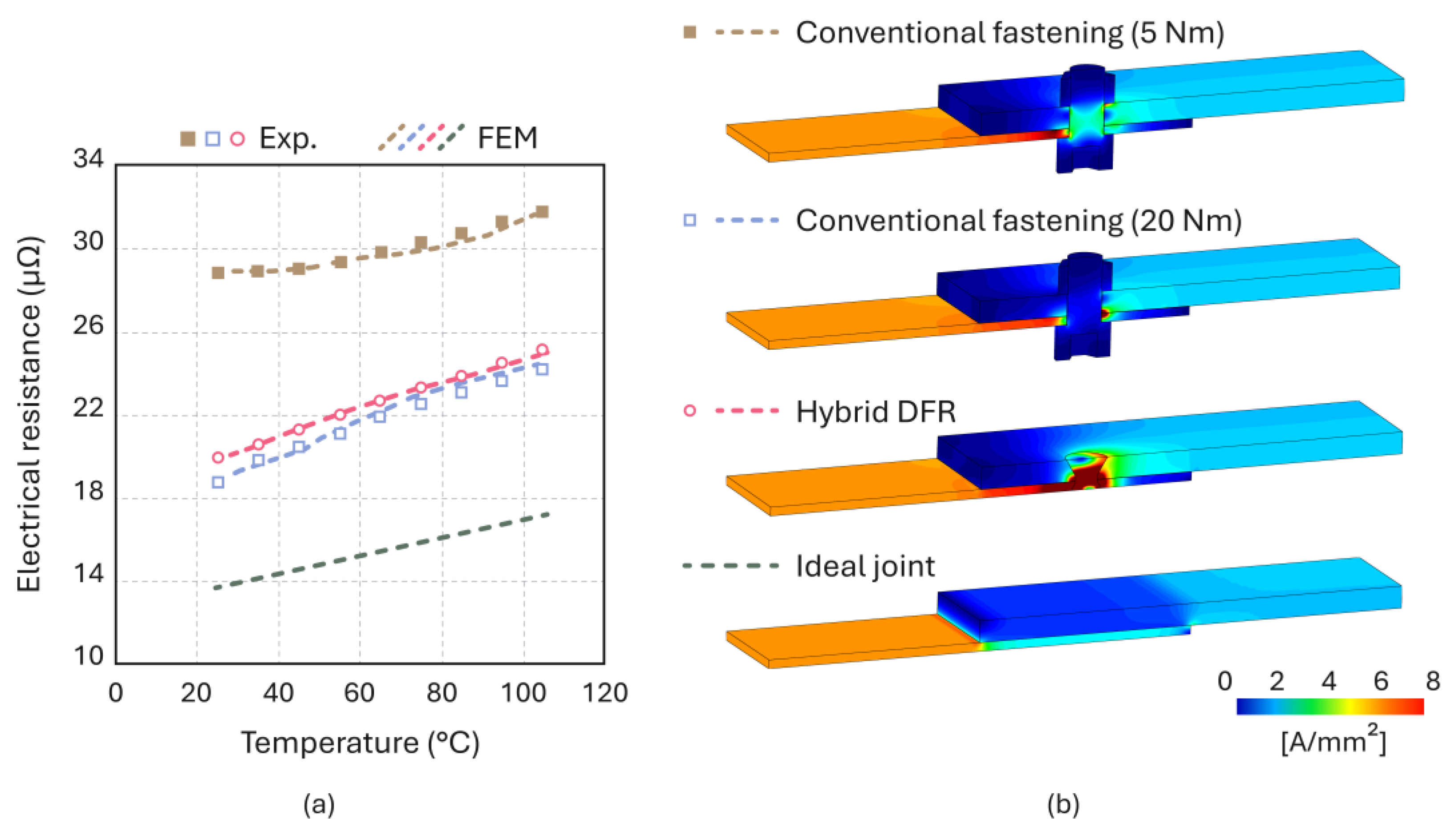
3.3. Thermo-Electrical Performance of the Joints

The thermo-electrical performance of the new double flush riveted hybrid busbars was evaluated by measuring their electrical resistance across a range of service temperatures. The results were compared to those obtained from conventional fastened joints, as well as from ideal joints [17], which were defined as busbars where the copper and aluminum sheets are in perfect contact, eliminating the presence of rivets, fasteners, contaminants, or oxide films that typically hinder electrical conductivity.
To achieve this, experimentation and advanced three-dimensional finite element models were employed, similar to those depicted in Figure 7c. In the case of conventional fastened joints, the thermo-electrical simulation required applying normal tensile pressure to the bolts and nuts to replicate two different applied tightening torques ( T = 5 Nm and T = 20 Nm). The higher torque T = 20 Nm, leading to a higher application of pressure, was crucial as it optimized the contact area by effectively flattening surface asperities and penetrating through any existing contaminants or oxide films, thus significantly minimizing the contact resistance of the joints.
Figure 12a illustrates how electrical resistance changes with temperature for the newly proposed double-flush riveted, conventional fastened, and ideal hybrid busbar joints. The ideal hybrid busbar joints exhibit the minimum theoretical achievable electrical resistances.
The first observation from the figure is that the electrical resistance increases nearly linearly with temperature, consistently rising from left to right. This behavior directly corresponds to the temperature-dependent increase in electrical resistivity that was previously shown on Figure 4b. Moreover, the agreement between the experimental results and finite element predictions is excellent, which allows concluding that the finite element models serve as accurate digital twins of the real hybrid busbar joints.
The second observation is that the new double-flush riveted joints exhibit similar electrical performance compared to conventional fastened joints with a tightening torque T = 20 Nm but performs much better than conventional fastened joints with a tightening torque T = 5 Nm—approximately 30% lower electrical resistance at ambient temperature. This result is important because fastened joints experience relaxation of the tightening torque over time, and T = 5 Nm replicates a near-loosening condition responsible for low normal pressures and, therefore, for high electric resistivity across the interface layer.
The enhanced results achieved through the novel double-flush riveting process can be attributed to a reduction in disruptions to the current density (see Figure 12b). The form- and force-closed mechanisms created by double-flush riveting promote a more uniform distribution of pressure across the overlap region. This contrasts with the significant disruptions seen in the bolt–nut assemblies of fastened joints, particularly when the tightening torque is low.
However, the electrical resistance of the double-flush riveted busbar joints remains higher than that of the ideal hybrid busbar joints, which represents the optimal current flow for the specific busbar geometry. This emphasizes the importance of using multiple rivets to maximize the contact area between overlapping sheets, thereby optimizing the electrical performance of the hybrid busbars, in real-world electrical service conditions.

4. Conclusions

The novel double-flush riveting process for assembling hybrid busbars made from aluminum and copper sheets of varying thicknesses involves a series of operations, including drilling, forging, and plastic deformation using copper cylindrical rivets to create a form- and force-closed mechanical joint. The forging step is crucial for shaping countersunk holes with tapered surface angles of α = 30°, which enhances interlocking distances compared to the original double-flush riveting process, where a breakout angle below 15° resulted in weaker interlocks. The new process also allows for the assembly of sheets with varying thicknesses (2 mm and 5 mm), overcoming a significant limitation of the original double-flush riveting.
Comprehensive experimental and numerical analyses—encompassing material flow assessments, precise force measurements, thorough evaluations of structural integrity via destructive testing, and electrical resistance measurements—have conclusively demonstrated that the novel double-flush riveting process yield strong and reliable hybrid busbar joints. These findings suggest that the new process is a viable alternative to conventional fastening, offering robust performance in real-world electrical service conditions.
Comparisons between double-flush riveted and bolted joints reveal similar electrical performance when the bolted joints are tightened with a torque T = 20   Nm . However, the electrical resistance of double-flush riveted joints is significantly better (30% lower) than that of bolted joints when a tightening torque T = 5   Nm , which simulates a condition of eventual self-loosening in the bolt–nut assembly, is used.

Author Contributions

Conceptualization, R.F.V.S. and C.M.A.S.; methodology, R.F.V.S. and J.P.M.P.; software, R.F.V.S., J.P.M.P., and M.P.F.; validation, I.M.F.B., C.M.A.S., and P.A.F.M.; formal analysis, R.F.V.S., M.P.F., and J.P.M.P.; investigation, R.F.V.S., M.P.F., J.P.M.P., I.M.F.B., C.M.A.S., and P.A.F.M.; resources, C.M.A.S. and P.A.F.M.; data curation, R.F.V.S., M.P.F., and J.P.M.P.; writing—original draft preparation, R.F.V.S. and P.A.F.M.; writing—review and editing, J.P.M.P., I.M.F.B., and C.M.A.S.; visualization, M.P.F.; supervision, R.F.V.S. and I.M.F.B.; project administration, J.P.M.P., C.M.A.S., and P.A.F.M.; funding acquisition, J.P.M.P. and P.A.F.M. All authors have read and agreed to the published version of the manuscript.

Funding

This research was funded by Fundação para a Ciência e a Tecnologia of Portugal (FCT) and IDMEC via the project LAETA Base Funding (DOI: 10.54499/UIDB/50022/2020).

Data Availability Statement

The original contributions presented in this study are included in the article. Further inquiries can be directed to the corresponding author.

Acknowledgments

The authors would like to acknowledge the support provided by Fundação para a Ciência e a Tecnologia of Portugal (FCT) and IDMEC for its financial support via the project LAETA Base Funding (DOI: 10.54499/UIDB/50022/2020). Rui F.V. Sampaio would also like to acknowledge the support received under PhD Studentship 2022.12351.BD.

Conflicts of Interest

The authors declare no conflicts of interest.

References

  1. Chastel, Y.; Passemard, L. Joining Technologies for Future Automobile Multi-Material Modules. Procedia Eng. 2014, 81, 2104–2110. [Google Scholar] [CrossRef]
  2. Casalino, G. Advances in Welding Metal Alloys, Dissimilar Metals and Additively Manufactured Parts. Metals 2017, 7, 32. [Google Scholar] [CrossRef]
  3. Cavezza, F.; Boehm, M.; Terryn, H.; Hauffman, T. A Review on Adhesively Bonded Aluminium Joints in the Automotive Industry. Metals 2020, 10, 730. [Google Scholar] [CrossRef]
  4. Fernando, S. Mechanisms and prevention of vibration loosening in bolted joints. Aust. J. Mech. Eng. 2005, 2, 73–92. [Google Scholar] [CrossRef]
  5. Li, D.; Chrysanthou, A.; Patel, I.; Williams, G. Self-piercing riveting-a review. Int. J. Adv. Manuf. Technol. 2017, 92, 1777–1824. [Google Scholar] [CrossRef]
  6. He, X. Clinching for sheet materials. Sci. Technol. Adv. Mater. 2017, 18, 381–405. [Google Scholar] [CrossRef] [PubMed]
  7. Buffa, G.; Fratini, L.; La Commare, U.; Römisch, D.; Wiesenmayer, S.; Wituschek, S.; Merklein, M. Joining by forming technologies: Current solutions and future trends. Int. J. Mater. Form. 2022, 15, 27. [Google Scholar] [CrossRef]
  8. Wronicz, W.; Kaniowski, J.; Malicki, M.; Kucio, P.; Klewicki, R. Experimental and Numerical Study of NACA and Conventional Riveting Procedure. Fatigue Aircr. Struct. 2017, 2017, 157–170. [Google Scholar] [CrossRef]
  9. Melhem, G.N. Aerospace Fasteners: Use in Structural Applications. In Encyclopedia of Aluminum and Its Alloys; CRC Press: Boca Raton, FL, USA, 2019; ISBN 978-1-351-04563-6. [Google Scholar]
  10. Zeng, C.; Xue, J.T.; Liu, X.Y.; Tian, W. Design variables influencing the fatigue of Al 2024-T3 in riveted aircraft lap joints: Squeeze force and initial fit tolerance. Int. J. Fatigue 2020, 140, 105751. [Google Scholar] [CrossRef]
  11. Zhang, M.; Cao, Z.; Guo, Y.; Cao, Y.; Zheng, G.; Huo, L. Stress, damage, and fatigue performance analysis of CFRP/Al double-sided countersunk riveted joints with variable rivet-hole clearance. Int. J. Fatigue 2024, 186, 108385. [Google Scholar] [CrossRef]
  12. Li, G.; Shi, G.; Bellinger, N.C. Studies of Residual Stress in Single-Row Countersunk Riveted Lap Joints. J. Aircr. 2012, 43, 592–599. [Google Scholar] [CrossRef]
  13. Qu, L.; Li, P.; Lv, G.; Li, J.; Luo, X. Rivet Structural Design and Process Optimization for the Double-Sided Countersunk Riveting of Composite Wedge Structures. Aerospace 2024, 11, 165. [Google Scholar] [CrossRef]
  14. Hasirci, Z.; Cavdar, I.H.; Ozturk, M. Modeling and Link Performance Analysis of Busbar Distribution Systems for Narrowband PLC. Radioengineering 2017, 26, 611–620. [Google Scholar] [CrossRef]
  15. Sampaio, R.F.V.; Larue, P.; Pragana, J.P.M.; Bragança, I.M.F.; Silva, C.M.A.; Martins, P.A.F. Double-Flush Riveting by Punching and Compression. J. Adv. Join. Process. 2023, 8, 100155. [Google Scholar] [CrossRef]
  16. Da Silva, B.F.A.; Kasaei, M.M.; Akhavan-Safar, A.; Carbas, R.J.C.; Marques, E.A.S.; Da Silva, L.F.M. Failure Behavior of Hole Hemmed Joints with a Novel Configuration for Hybrid Busbars in Electric Vehicle Batteries. Eng. Fail. Anal. 2025, 167, 109019. [Google Scholar] [CrossRef]
  17. Sampaio, R.F.; Pragana, J.P.; Bragança, I.M.; Silva, C.M.; Martins, P.A. Thermo-Electrical Performance of Hybrid Busbars: An Experimental and Numerical Investigation. Proc. Inst. Mech. Eng. Part L J. Mater. Des. Appl. 2023, 237, 70–80. [Google Scholar] [CrossRef]
  18. Olafsson, D.; da Silva, P.S.V.; Vesanko, J. Characterization of FSW of Aluminium to Copper for Electrical Busbars. In Proceedings of the International Institute of Welding Annual Assembly and International Conference, Bali, Indonesia, 15–20 July 2018; p. III–1859-18. [Google Scholar]
  19. ASTM E8/E8M; Standard Test Methods for Tension Testing of Metallic Materials. ASTM International: West Conshohocken, PA, USA, 2024. [CrossRef]
  20. ASTM E9-89A; Standard Test Methods for Compression Testing of Metallic Materials at Room Temperature. ASTM International: West Conshohocken, PA, USA, 2010. [CrossRef]
  21. Kumar, N.; Masters, I.; Das, A. In-Depth Evaluation of Laser-Welded Similar and Dissimilar Material Tab-to-Busbar Electrical Interconnects for Electric Vehicle Battery Pack. J. Manuf. Process. 2021, 70, 78–96. [Google Scholar] [CrossRef]
  22. IEEE C37.20.2-2015; IEEE Standard for Metal-Clad Switchgear. IEEE: New York, NY, USA, 2015. [CrossRef]
  23. MatWeb Medium Carbon Steel of Class 8.8 Data Sheet. Available online: https://www.matweb.com/ (accessed on 4 January 2025).
  24. Silva, C.M.A.; Pragana, J.P.M.; Sampaio, R.F.V.; Bragança, I.M.F.; Martins, P.A.F. Advanced Double-Flush Riveting for Multistage Forming Tools. CIRP Ann. Manuf. Technol. 2025, in press. [Google Scholar] [CrossRef]
  25. ISO 14270:2016; Resistance Welding—Destructive Testing of Welds—Specimen Dimensions and Procedure for Mechanized Peel Testing Resistance Spot, Seam and Embossed Projection Welds. International Organization for Standardization: Geneva, Switzerland, 2021.
  26. Nielsen, C.V.; Martins, P.A.F. Finite Element Flow Formulation. In Metal Forming; Elsevier: Amsterdam, The Netherlands, 2021; pp. 181–249. ISBN 978-0-323-85255-5. [Google Scholar]
  27. Banabic, D. FE-Models of the Sheet Metal Forming Processes. In Sheet Metal Forming Processes; Springer: Berlin/Heidelberg, Germany, 2010; pp. 1–25. ISBN 978-3-540-88112-4. [Google Scholar]
  28. Studer, F.J. Contact Resistance in Spot Welding. Weld. J. 1939, 18, 374–380. [Google Scholar]
Figure 1. Classification of the leading technologies to fabricate lap joints with schematic figures showing some well-known processes.
Metals 15 00521 g001
Figure 2. (a) The original double-flush riveting processes for the assembly of aluminum sheets and (b) the novel double-flush riveting processes for the assembly of hybrid busbars made from aluminum and copper sheets with varying thicknesses.
Metals 15 00521 g002
Figure 3. Geometry of the (a) unit cells and (b) rivets utilized in the experiments (dimensions are in mm).
Metals 15 00521 g003
Figure 4. (a) True stress vs. true strain curves and (b) evolution of electrical resistivity with temperature for the medium carbon steel, aluminum AA6082-T6 and copper C11000.
Metals 15 00521 g004
Figure 5. Schematic representation of (a) the geometric variables resulting from sheet forging and (b) the placement of rivets between the aluminum and copper sheets.
Metals 15 00521 g005
Figure 6. Schematic representation of the destructive (a) shear and (b) peeling tests.
Metals 15 00521 g006
Figure 7. Initial and final computed meshes for the (a) sheet forging of the AA6082-T6 aluminum sheet and (b) double-flush riveting at the beginning (left) and end (right) of joining. The three-dimensional model used for the thermo-electrical analysis of the hybrid busbar is shown in (c).
Metals 15 00521 g007
Figure 8. (a) Numerical simulation of the forging operation used to shape countersunk holes in C11000 electrolytic copper sheets, along with the finite element computed distribution of strain for the (b) C11000 electrolytic copper and (c) AA6082-T6 aluminum sheets. Also included are photographs of the experimental cross-sections for both sheet materials.
Metals 15 00521 g008
Figure 9. (a) Finite element computed distribution of radial stress σ r at the end of double-flush riveting and (b) a photograph of an experimental cross-section.
Metals 15 00521 g009
Figure 10. Experimental (solid lines) and finite element-predicted (dashed lines) evolutions of the force with displacement for the (a) forging and (b) joining by plastic deformation stages of double flush riveting of hybrid busbars made from AA6082-T6 aluminum and C11000 electrolytic copper sheets with thicknesses of 5 mm and 2 mm, respectively.
Metals 15 00521 g010
Figure 11. Experimental evolutions of the force with displacement for the (a) shear and (b) peel destructive tests performed on the hybrid busbars made from AA6082-T6 aluminum and C11000 electrolytic copper sheets with thicknesses of 5 mm and 2 mm, respectively.
Metals 15 00521 g011
Figure 12. (a) Experimental and finite element predicted evolutions of electrical resistance with temperature and (b) finite element distributions of current density (A/mm2) for the newly proposed double-flush riveted, conventional fastened, and ideal hybrid busbar joints.
Metals 15 00521 g012
Disclaimer/Publisher’s Note: The statements, opinions and data contained in all publications are solely those of the individual author(s) and contributor(s) and not of MDPI and/or the editor(s). MDPI and/or the editor(s) disclaim responsibility for any injury to people or property resulting from any ideas, methods, instructions or products referred to in the content.

