Article

Influence of Ni60-WC Bionic Unit on the Wear Performance of 20CrMnTi Steel Prepared via Laser Cladding

School of Mechanical and Civil Engineering, Jilin Agricultural Science and Technology University, Jilin 132101, China
*
Authors to whom correspondence should be addressed.
Metals 2025, 15(5), 507; https://doi.org/10.3390/met15050507
Submission received: 8 April 2025 / Revised: 24 April 2025 / Accepted: 29 April 2025 / Published: 30 April 2025

Abstract

:
In recent years, the field of bionic engineering has advanced at a remarkable pace. Numerous engineering challenges have been addressed through inspiration drawn from biological organisms in nature. In this paper, laser cladding was employed to fabricate a bionic unit inspired by the radial ribs of the bivalve shell surface morphology on 20CrMnTi steel, with the aim of enhancing its wear performance. The metallic powder used in the experiments was prepared by blending Ni60 alloy powder with tungsten carbide (WC) in a predetermined ratio. The WC content was maintained within a mass percentage range of 15% to 60% in the composite powder system. The microstructure and properties of the bionic unit were characterized using scanning electron microscopy (SEM), X-ray diffraction (XRD), and a hardness tester, while its dry sliding wear resistance was evaluated using a block-on-ring tribometer. The influence of the WC content on the microstructure, hardness, surface roughness, and wear performance of the bionic unit was investigated. The experimental results revealed that the bionic unit exhibited a dual microstructure comprising equiaxed crystals and fine dendritic structures. The incorporation of WC induced pronounced grain refinement, while the dispersed WC particles formed effective metallurgical bonding with the Ni-substrate. A positive correlation was observed between the WC content and hardness, with peak hardness reaching 1008 HV0.2 at 60% WC. Tribological analysis demonstrated a wear mechanism transition from dominant abrasive wear to a hybrid abrasive–adhesive wear. The wear volume of the bionic unit decreased with increasing WC content, and the extent of damage was reduced.

1. Introduction

With the rapid advancement of modern industry, mechanical equipment is evolving toward higher power and heavier loads, while service environments continue to deteriorate. Components operating under high-temperature and high-pressure conditions are often subject to damage. Wear, corrosion, and fatigue are the three most common forms of component failure, leading to significant economic losses. The microstructure and properties of metallic materials are directly related to their failure mechanisms. To prevent the premature failure of components, various surface engineering techniques have been employed, including plasma spraying, chemical vapor deposition, and physical vapor deposition [1,2,3,4,5,6]. The application of these surface engineering techniques effectively mitigates component damage, enhances material utilization, and reduces economic losses.
Laser cladding is a surface modification technique that employs a high-energy density laser beam as a heat source to rapidly melt powders with specific properties onto the surface of a substrate, forming a protective or functional coating [7,8,9]. The resulting cladding layer establishes a strong metallurgical bond with the substrate through the processes of melting and solidification. This bond exhibits a strength comparable to, or even exceeding, that of the base material—significantly superior to the mechanical bonding seen in conventional surface treatment methods such as thermal spraying and electroplating [10,11]. As a result, the coating demonstrates excellent adhesion and is resistant to delamination under harsh operating conditions. During the laser cladding process, the laser energy is highly concentrated and applied over a short duration, resulting in low heat input to the substrate. This minimizes the risk of thermal deformation and grain coarsening, which are common issues associated with high-temperature processing. Laser cladding is particularly well-suited for the repair and localized strengthening of precision components. By precisely adjusting key processing parameters, such as the laser power, scanning speed, and powder feeding rate, the original characteristics of the powder materials can be largely preserved [12,13]. Commonly used powders include self-fluxing alloy powders, ceramic particles, and various composite materials. The composition of the powders can be flexibly tailored to meet specific functional requirements, enabling the fabrication of customized coatings. The laser beam offers micrometer-level positioning accuracy, allowing for the precise treatment of localized areas and even the surface modification of complex geometries. When integrated with CNC systems and robotic arms, laser cladding can be fully automated, making it ideal for large-scale production and the thermal processing of intricate structural components [14]. Furthermore, laser cladding can be combined with additive manufacturing technologies to enable integrated rapid prototyping and component repair [15]. Compared to replacing an entire part, laser cladding allows for the direct restoration and reinforcement of worn or damaged surfaces. This process achieves a material utilization rate of over 95%, significantly reducing resource consumption and production costs. Additionally, the process offers strong controllability and a low scrap rate. Laser cladding has been widely adopted in industries such as aerospace, energy and power, mold manufacturing, automotive production, and petrochemicals. It is especially advantageous for the remanufacturing of high value-added components [16]. With ongoing advancements in laser technology, powder preparation, and intelligent control systems, the applications of laser cladding are expected to continue to expand, driving further innovation and evolution within the manufacturing sector.
In recent years, biomimetic engineering has introduced innovative solutions to improve material performance by imitating the unique structures, functions, and behaviors of living organisms. For example, the radial ribs on shell surfaces play a crucial role in enhancing wear resistance. These ribs help shells disperse and absorb energy when subjected to sediment and water flow impacts, thereby reducing direct damage. The diverse structural characteristics of shells allow them to maintain their integrity and functionality in complex natural environments over long periods. They also improve impact toughness, making shells more resistant to breaking or deformation under external forces, which further enhances their wear resistance. Inspired by these natural structures, biomimetic designs based on shell radial ribs have been applied to various materials [17,18].
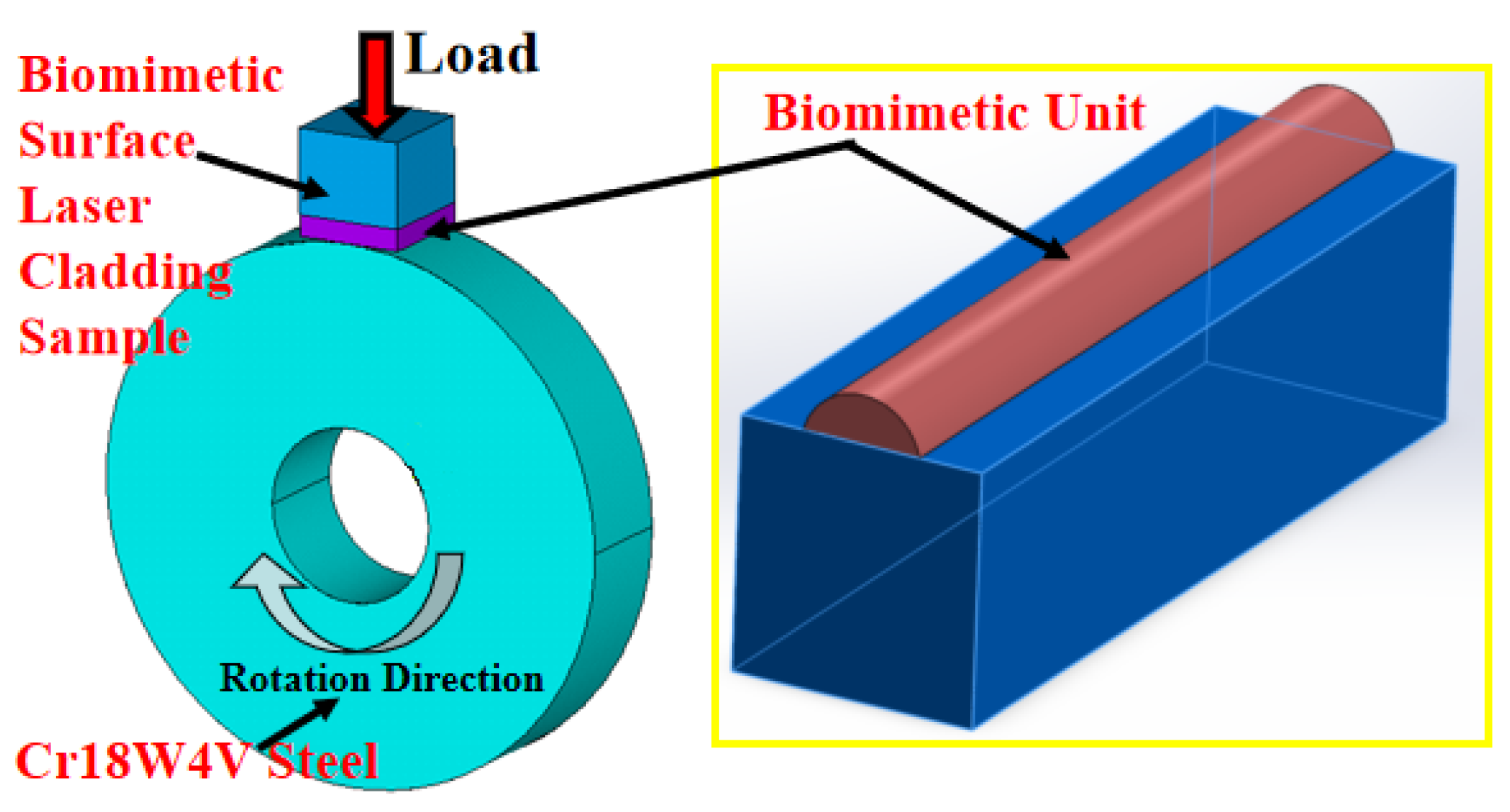
20CrMnTi steel is a widely used structural steel with excellent mechanical and processing properties, commonly employed in the automotive and tractor industries. It is particularly valued in the production of critical components such as gears, shafts, and pistons. However, under harsh working conditions, severe surface wear can compromise its performance, making it difficult to meet operational demands. In this paper, a composite powder composed of Ni60 alloy powder and tungsten carbide (WC) was used. Using laser cladding technology, a biomimetic unit was fabricated on the surface of 20CrMnTi steel to enhance its wear resistance and reliability. Size measurements, microstructure observations, hardness tests, and surface roughness analyses of the biomimetic unit were conducted to investigate the effect of different WC contents on its wear performance. This research aims to provide new insights and methods for advancing surface engineering technology for metallic materials.

2. Materials and Methods

2.1. Material and Laser Cladding

In this experiment, 20CrMnTi steel was used as the substrate. The particle size of Ni60 alloy powder was 320 mesh, while the WC powder had a particle size range of 60–200 mesh. The chemical composition of 20CrMnTi steel, Ni60 alloy powder, and WC is shown in Table 1. Both the Ni60 alloy powder and WC powder had spherical shapes. The laser processing parameters were kept constant, with the WC content being the only variable. Table 2 presents the laser processing parameters (Guangzhou Xingrui Laser Technology Co., Ltd., Guangdong, China), powder ratios, and sample numbers for each specimen. The laser cladding test was performed using a 3 kW high-power fiber laser. The laser processing method employed was coaxial powder feeding. Argon (Ar) gas was used as a protective atmosphere at a flow rate of 20 L/min to prevent material oxidation.
The reason for choosing WC instead of TiC or SiC as ceramic particles to be added to Ni60 alloy powder is as follows.
TiC was not chosen as the ceramic reinforcement for the Ni60 alloy powder for several reasons. Firstly, the self-fluxing elements present in Ni60 alloy significantly reduce the surface tension of the melt pool, thereby improving the wettability of the WC particles. The contact angle between liquid Ni60 alloy and WC is lower than that between Ni60 and TiC, indicating that WC has superior wettability. In contrast, TiC exhibits relatively poor wettability with Ni60 alloy, which results in the agglomeration and suspension of the TiC particles in the melt pool. Secondly, during the laser cladding process, some of the WC particles melt, releasing W and C atoms that react with elements such as Ni and Fe to form a variety of tough carbides. However, when TiC reacts with elements in the Ni60 alloy, brittle intermetallic compounds such as Ni3Ti are formed. These brittle phases weaken the metallurgical bond between the coating and the substrate, reducing the overall bonding strength. Thirdly, the reaction between WC and the Ni60 alloy leads to the formation of W2C, a carbide known for its good toughness, which helps mitigate coating embrittlement. In contrast, the interfacial reactions between TiC and Ni60 alloy tend to form brittle phases such as Ni3Ti and NiTi. These brittle compounds increase the likelihood of premature coating failure due to crack initiation and propagation.
SiC was not chosen as the reinforcing ceramic phase in Ni60 alloy powder for several key reasons. Firstly, although the melting point of SiC is comparable to that of WC, WC has a higher melting point than Ni60 alloy, enabling it to remain largely undissolved during the rapid melting and solidification process of laser cladding. This allows the WC particles to act as hard phases within the coating, significantly enhancing the wear resistance. In contrast, SiC tends to decompose in the nickel-based melt pool, leading to the formation of brittle phases such as Ni3Si. Additionally, free carbon released during SiC decomposition may react with nickel to form Ni3C, which contributes to reduced coating hardness and increased brittleness. Secondly, the thermal expansion mismatch between the ceramic particles and the metal matrix plays a critical role in coating reliability. WC and Ni60 alloy have relatively similar coefficients of thermal expansion, which minimizes interfacial thermal stress during cooling and reduces the risk of particle detachment or cracking. However, the thermal expansion mismatch between SiC and Ni60 alloy is significantly greater. This mismatch generates considerable thermal stress at the interface during cooling, leading to the formation of microcracks around SiC particles and even coating delamination, which severely compromises the bonding strength and structural integrity of the coating. Thirdly, the wettability of the ceramic particles by the molten matrix is crucial for achieving uniform dispersion and strong interfacial bonding. Liquid Ni60 alloy exhibits good wettability toward WC particles, allowing them to be evenly distributed in the melt pool via convection and facilitating metallurgical bonding with the substrate. In contrast, the wettability of SiC by liquid Ni60 alloy is relatively poor, making SiC particles more likely to agglomerate or float to the melt pool surface. As a result, SiC cannot be uniformly dispersed in the coating, leading to nonhomogeneous microstructures and compromised coating performance.

2.2. Surface Roughness Measurement

The surface roughness of the samples was assessed by performing five measurements using a Veeco Wyko NT1100 optical profiler (Veeco Instruments Inc., Tucson, AZ, USA). The sampling length for calculating the arithmetic mean roughness (Ra) was carefully selected to ensure accuracy.

2.3. Microstructure Observation and XRD Measurement

Microstructural characterization was conducted using a metallographic microscope. Scanning electron microscopy (SEM) (Japan Electronics Corporation (JEOL), Tokyo, Japan) equipped with an energy-dispersive X-ray spectroscopy (EDS) detector was employed to analyze the chemical element distribution in specific regions. Phase composition analysis was carried out using X-ray diffractometry (XRD) (Rigaku Corporation, Tokyo, Japan) with Cu-Kα radiation, operating at 40 kV and 30 mA. The diffraction patterns were recorded over a 2θ range of 20–90° with a step size of 0.02°.

2.4. Hardness Measurement

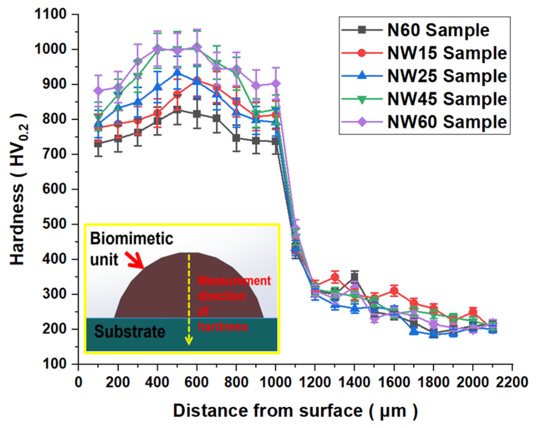
Hardness profiling was performed using a Vickers hardness tester (Mitutoyo, Kawasaki, Kanagawa Prefecture, Japan). Measurements were taken along the depth direction using a pyramidal diamond indenter under a 200 gf load, with a dwell time of 10 s. A calibrated depth-step motor ensured precise indent spacing at 100 μm intervals along the cross-sectional gradient. To enhance measurement reliability, three measurements were taken at each depth station within a 50 μm lateral spacing. The reported hardness value represents the arithmetic mean of three valid impressions. To ensure accurate hardness measurements, approximately ten exploratory indentations and readings were typically performed. If significant discrepancies were observed between any two measurements, additional measurements were taken. This method increased the number of random samples, thereby minimizing measurement error and enhancing the reliability of the hardness data. In the hardness measurement of the biomimetic unit, the depth direction referred to the vertical axis extending from the surface of the biomimetic unit into the substrate. Hardness values were measured point by point along this direction to analyze the variation in hardness across the cross-section of the biomimetic unit.
Prior to performing hardness measurements and microstructural observations, the biomimetic unit must undergo meticulous sample preparation. This process involved four main steps: “wire cutting”, “embedding and fixing”, “grinding and polishing”, and “etching”. The objective of these steps was to obtain a flat, scratch-free, and clean cross-section suitable for precise testing. The detailed procedures are as follows.
Wire Cutting: The sample was cut using a slow wire cutting method (cutting speed ≤ 5 mm/min) along a direction perpendicular to the laser scanning path. A specialized cutting fluid was used throughout the process to thoroughly cool the cutting area, minimizing thermal damage and ensuring a smooth surface. After cutting, the surface was cleaned with anhydrous ethanol to remove oil residues and metal debris.
Embedding and Fixing: The cut surface of the biomimetic unit was placed face-down into the mold of the embedding machine. Phenolic resin particles were used to fill the mold. The embedding process was carried out at a temperature of 150 °C and a pressure of 15 MPa, which was maintained for 15 min. After the sample had cooled, it was demolded to obtain the embedded specimen.
Grinding and Polishing: This step included rough grinding, fine grinding, and fine polishing. Its purpose was to remove the damaged surface layer caused by cutting and embedding, ultimately producing a flat, mirror-like cross-section free of scratches. Rough grinding used diamond grinding discs with particle sizes ranging from 180 # to 600 #. The embedded sample was held by hand, placed on a diamond grinding disc, and pressed evenly downward. Grinding must be performed in a single direction to avoid random scratches that can result from circular motion. Before replacing each type of diamond grinding disc, it was necessary to rinse the sample with clean water and to clean the embedded sample with ultrasonic waves for 5 min to prevent secondary scratches caused by residual coarse particles. The surface of the sample was observed under a microscope until the wire cutting marks on the surface of the sample were completely removed and a bright metallic luster appeared. Diamond sandpaper with a particle size of 800–2000 # was used for fine grinding. Every time the sandpaper was replaced, the grinding direction of the sample needed to be rotated 90 ° to facilitate the removal of scratches left by the previous grinding. In the polishing step, diamond suspension with a particle size of 5 μm and a polishing cloth were used. The speed of the polishing machine was 200 rpm. The polishing time was 10 min. The sample was gently pressed until the surface had a mirror-like state. There were no visible scratches. Then, the sample could be subjected to hardness testing.
Etching: If microstructural observation is to be conducted using scanning electron microscopy (SEM), the sample must undergo an etching process. This involved using cotton swabs soaked in aqua regia to gently wipe the polished surface of the sample. The etching duration was 30 s. After etching, the polished surface should be immediately rinsed with clean water, followed by dehydration using anhydrous ethanol. Finally, the sample was dried using cold air.

2.5. Wear Tests

As shown in Figure 1, the wear test was conducted using a block-on-ring tribometer. The sample dimensions were 17 mm × 7 mm × 7 mm. This paper focused on the effect of a single biomimetic unit on the wear performance of 20CrMnTi steel. Investigating the impact of interactions among multiple biomimetic units on the wear resistance of 20CrMnTi steel will be the focus of our future research. Wear mass loss was quantified through gravimetric analysis using a precision balance, comparing pre- and post-test weights. The final wear amount at each test point was determined as the average of three repeated experiments. The procedure for measuring sample weight loss is as follows. Prior to the wear test, the sample was immersed in anhydrous ethanol and cleaned using an ultrasonic cleaner to remove surface contaminants. After cleaning, the sample was handled with clean tweezers and placed in a drying oven set at 60 °C for 15 min. It is crucial to ensure that the electronic balance is positioned on a stable surface and that the ambient temperature and humidity remain constant. Once dried, the sample was gently placed at the center of the balance tray, and the balance door was closed. After the reading stabilized, the sample’s weight was recorded. Each sample was weighed three times, and the average value was taken as the initial weight to reduce measurement error. After the wear test, the sample was again handled with tweezers to avoid contamination. Loose debris on the sample surface was gently removed using a soft-bristled brush. If stubborn residues remained, the sample was cleaned in acetone using an ultrasonic cleaner for 2 min. After cleaning, the drying procedure was repeated to ensure no residual liquid remained on the surface. The same balance was used to weigh the sample again, with the measurement repeated three times. The average of these readings was recorded as the final weight of the sample. Under the same experimental conditions, it was found that the results of three repeated experiments were basically the same, indicating that the repeatability of the wear experiment at each test point was good. The testing machine operated at a speed of 200 rev/min, with each experiment lasting 60 min. A load of 200 N was applied, and no lubricant was used during testing. The grinding roller was made of Cr18W4V steel, with a hardness of approximately 595 HV0.2.

3. Results and Discussion

3.1. Size

Figure 2a shows the cross-sectional morphology of the biomimetic unit in the NW60 sample. WC exhibited good compatibility with nickel-based alloys. The bonding between the biomimetic unit and the substrate was dense, with minimal defects. As shown in Figure 2b, the WC content significantly influenced the width and height of the biomimetic unit. In the N60 sample, the width and height of the biomimetic unit were 994.94 μm and 4668.43 μm, respectively. In the NW15 sample, the width increased to 4699.91 μm, while the height slightly decreased to 987.65 μm. The W element released during the melting of WC reduced the surface tension of the molten pool, enhanced its wettability on the substrate, and promoted lateral spreading, resulting in an increased biomimetic unit width [19]. Additionally, the localized melting of WC increased the thermal conductivity of the liquid metal, accelerating heat transfer to the substrate, which suppressed the longitudinal expansion of the molten pool and led to a decrease in the biomimetic unit height [20]. When the WC content reached 25% and 45%, the width of the biomimetic unit stabilized at 4595.82 μm and 4580.25 μm, respectively. However, its height decreased significantly to 945.67 μm compared to the NW15 sample. The presence of unmelted WC acted as a secondary phase, hindering the flow of liquid metal and increasing its viscosity [21,22]. This higher viscosity restricted the lateral expansion of the molten pool, causing the width of the biomimetic unit to stagnate. In the NW60 sample, both the width and height of the biomimetic unit decreased simultaneously, dropping to 4512.67 μm and 932.34 μm, respectively. During the laser cladding process, the high thermal conductivity of unmelted WC caused rapid cooling and solidification of the molten material [23]. At a high WC content, accumulated unmelted WC formed a hard barrier that obstructed the flow of liquid metal, limiting the overall growth of the biomimetic unit.

3.2. Microstructure

Figure 3 presents the longitudinal cross-sections of the biomimetic unit for each sample. When the laser cladding layer formed a metallurgical bond with the substrate, a white strip, known as the bonding line, was generated between the two. In this paper, the bonding strength between the biomimetic unit and the substrate was not measured. The precise bonding strength and the effect of the WC content on this property will be explored in future research. The laser cladding layer was formed through the rapid melting and solidification of nickel-based alloy powder and WC particles. At a low WC content, some WC particles decomposed at high temperatures, resulting in a relatively sparse distribution within the biomimetic unit. Due to the high density of WC, the remaining particles tended to settle at the bottom of the biomimetic unit. As the WC content increased, a greater number of WC particles were present in the molten pool, leading to their dispersion throughout the entire biomimetic unit. Regardless of the WC content, metallurgical bonding was achieved between the biomimetic unit and the substrate. The distribution of WC within the biomimetic unit significantly influenced its hardness and wear performance.
As shown in Figure 4a,b, the microstructure of the upper and middle parts of the biomimetic unit in the NW15 sample consisted of equiaxed crystals and dendritic crystals, respectively. The high energy of the laser beam was absorbed by the molten pool, which then rapidly cooled and solidified. The temperature gradient (G) at the interface between the edge of the molten pool and the substrate was relatively high, while the solidification rate (R) was relatively low, resulting in a high G/R ratio [24]. A higher G/R ratio promoted the epitaxial growth of dendrites along the heat flow direction and their tip-splitting growth. When the cooling rate was moderate, the G/R ratio between the edge and center of the molten pool decreased, promoting the formation of a compositionally supercooled zone [25,26]. The undercooling at the front of the solid–liquid interface increased, favoring the formation of equiaxed crystals inside the molten pool. Additionally, this paper did not analyze the specific values of the temperature gradient (G) and solidification rate (R) within the melt pool as influenced by the WC content. These parameters will be examined in future studies through numerical simulations to better understand the thermal dynamics during the laser cladding process. As shown in Figure 4c, compared to the microstructure of the biomimetic unit in the N60 sample, the grain size of the NW15 sample was finer. In terms of material composition, the N60 sample contained 0% WC, while the NW15 sample contained 15% WC. The results clearly indicate that the addition of WC particles contributes to the refinement of the microstructure within the biomimetic unit.
At a low WC content, heat conduction within the molten pool mainly relied on the nickel-based alloy. The input of laser energy raised the temperature of the molten pool and lowered the cooling rate, promoting grain growth and resulting in the formation of coarse equiaxed grains and dendrites. At this stage, the WC partially melted, releasing W and C elements that diffused into the liquid metal, forming a γ(Ni, Fe) solid solution and carbides. As the WC content increased, unmelted WC particles began to disperse throughout the molten pool. As shown in Figure 4d, the dendrite size in the biomimetic unit decreased, and equiaxed crystallization occurred. Furthermore, the unmelted WC particles acted as heterogeneous nucleation sites, promoting non-uniform nucleation and further refining the grain size [27]. As shown in Figure 4e, when the WC content was high, the cooling and solidification of the molten pool occurred more rapidly due to the enhanced heat absorption of WC and the reduced thermal conductivity of the molten material. This rapid solidification suppressed grain growth and resulted in the formation of finer grains [28]. It is worth noting that Figure 4f shows the fragmentation of dendrites and the formation of discontinuous network carbides in the NW60 sample.
Figure 5 shows the XRD patterns of each sample. The main phases present in the N60 sample were γ(Ni, Fe) and Ni3Fe. After the addition of WC to the Ni-based alloy powder, diffraction peaks corresponding to WC appeared in all samples. A portion of the WC underwent chemical decomposition (WC → W + C) at high temperatures. The released C atoms were dissolved into the γ(Ni, Fe) solid solution. Subsequently, the remaining WC further reacted (WC → W2C + C), leading to the formation of W2C. The XRD patterns confirmed the presence of W2C diffraction peaks. With increasing WC content, the formation of γ(Ni, Fe) and Ni3Fe was suppressed, resulting in a weakening of their diffraction peak intensities. Meanwhile, the diffraction peaks of WC and W2C became stronger and gradually dominated the phase composition of the biomimetic unit. When the WC content reached 60%, the γ(Ni, Fe) diffraction peaks disappeared entirely. W2C, WC, and Ni3Fe became the primary phases in the NW60 sample. This phenomenon was mainly attributed to the local incomplete melting of the WC particles.
Figure 6 shows the point scan results of the chemical elements at various locations within the NW25 sample. The main chemical elements detected inside and between the grains were C, Si, Cr, Mn, Fe, Ni, and W. The types and contents of the chemical elements were very similar across different regions. As shown in Table 3, W was detected only in the equiaxed crystal (sampling point 2), while no W element was detected elsewhere. This observation confirms that the diffusion range of W after the dissolution of WC in the molten pool is very limited [29].
Figure 7 shows the EDS surface scan results of the chemical elements in the NW25 sample. In the unmelted WC particles, W and C were the main elements. The Fe element from the 20CrMnTi steel diffused into the laser cladding layer; however, due to the rapid cooling rate of the molten pool, the diffusion time and distance were limited. No Fe was detected inside the WC particles. In the nickel-based alloy region, the distribution of the other elements was relatively uniform. W was also present in the nickel-based alloy region and, according to XRD analysis, existed in the form of W2C. Overall, the distribution of the elements was uniform, with no obvious elemental segregation observed.

3.3. Hardness

Figure 8 presents the hardness curves of each sample, revealing a similar hardness trend across all specimens. The addition of WC significantly increased the hardness of all biomimetic units compared to the N60 sample. The highest hardness values for different WC contents were 912 HV0.2, 934 HV0.2, 1002 HV0.2, and 1008 HV0.2, respectively, showing a continuous increase with a higher WC content. The maximum hardness of each sample was observed in the subsurface layer, while the hardness decreased sharply with increasing depth. The upper and lower regions of the biomimetic unit exhibited lower hardness compared to the middle section due to the lower dissolution of WC, which resulted in a reduced formation of hard phases [30,31]. As the depth approached the boundary between the biomimetic unit and the substrate, the hardness trend stabilized. For a WC content of 15%, the hardness of the biomimetic unit ranged from 777 HV0.2 to 912 HV0.2. At high temperatures, W and C elements from WC dissolved into the eutectic phase between dendrites, while rapid cooling and solidification during laser cladding facilitated the precipitation of carbides and borides [32]. As the WC content increased, the hardness of the biomimetic unit continued to rise. At a WC content of 60%, the hardness ranged from 882 HV0.2 to 1008 HV0.2. Under non-equilibrium solidification conditions, an increase in non-uniform nucleation led to grain refinement in the biomimetic unit. According to the Hall–Petch equation, finer grains contribute to higher hardness. Additionally, undissolved WC particles acted as dispersed hard phases, further enhancing the hardness of the biomimetic unit [33].

3.4. Surface Roughness

As shown in Table 4, the surface roughness (Ra) of the biomimetic unit along the laser scanning direction was 1.002 μm, 1.294 μm, 1.514 μm, and 1.817 μm, respectively, for the different WC contents. The surface roughness increased with increasing WC content. Compared to the N60 sample (Ra = 0.65 μm), the roughness increased by 54.1%, 99.1%, 132.9%, and 179.5%, respectively. The WC content significantly influenced the surface roughness of the biomimetic unit. At a low WC content, the molten pool remained relatively smooth, with evenly distributed WC particles, resulting in minimal impact on the surface roughness. However, as the WC content increased, the viscosity of the molten pool increased, leading to uneven cooling and solidification. Some WC particles agglomerated and remained unmelted, obstructing the flow of the molten pool and reducing the surface regularity. Additionally, the in situ formation of other carbides caused volume expansion, squeezing surrounding materials and forming surface protrusions, further contributing to the increased roughness. While a lower WC content resulted in smoother surfaces, an insufficient number of WC particles could not adequately enhance the wear resistance of the material. Therefore, determining the optimal WC content through experimentation is crucial for achieving the best performance.

3.5. Wear Test Results

3.5.1. Wear Morphology

Figure 9a displays the wear morphology of the N60 sample, characterized by numerous plowing grooves, indicative of abrasive wear. Due to the relatively low hardness of the N60 biomimetic unit, the friction pair plowed its surface. White particles observed on the surface were identified as oxides, suggesting a wear mechanism involving both abrasive and oxidative wear. As shown in Figure 9b–d, the addition of WC to the Ni-based alloy powder altered the wear mechanism to include adhesive wear, abrasive wear, and oxidative wear. Frictional heating caused oxidation on the biomimetic unit’s surface, leading to the adhesion of metal oxides under high temperature and pressure [34]. Dark-colored sheet-like structures were observed adhering to the biomimetic unit but did not entirely cover it, leaving areas of the Ni-based alloy exposed. Elemental analysis (Figure 10) revealed high concentrations of Fe and O in these attachments, with Fe originating from the friction pair and O indicating oxidative wear. The Ni content was higher around these structures, signifying the presence of Ni-based alloys. During friction, the adhesive layers detached, causing adhesive wear. Additionally, debris acted as abrasive particles, further scratching and furrowing the surface [35,36]. During the wear process, intense friction between the biomimetic unit and the grinding roller generated substantial heat, leading to a rapid temperature rise at the contact interface. At elevated temperatures, the iron element in the material reacted with atmospheric oxygen to form iron oxides, primarily Fe2O3 and Fe3O4. The oxidation rate increased with temperature. Initially formed oxide films were subjected to mechanical stress, causing them to fracture and detach, resulting in the formation of fine oxide particles, commonly referred to as wear debris or abrasives. These detached oxides were further broken down and adhered to the surface of the biomimetic unit. Simultaneously, the freshly exposed surface underwent further oxidation, leading to a repetitive cycle of “oxidation → wear → re-oxidation”. At a higher WC content, exposed WC particles bore the load (Figure 11), reducing damage to the biomimetic unit. Since the WC was harder than the Ni-based alloys, increasing its content mitigated wear damage [37]. Overall, the wear resistance of the biomimetic unit was directly proportional to its hardness.

3.5.2. Coefficient of Friction

Figure 12 illustrates the variation in the friction coefficient of each biomimetic unit. During the steady-state wear stage, the minimum friction coefficients for the different WC contents were 0.198, 0.186, 0.187, and 0.193, respectively. The maximum values were 0.219, 0.205, 0.196, and 0.220, respectively. The average friction coefficients were 0.206, 0.199, 0.191, and 0.209, respectively. For comparison, the N60 sample exhibited minimum, maximum, and average friction coefficients of 0.177, 0.188, and 0.192, respectively. The addition of WC particles resulted in higher friction coefficients in all samples compared to the N60 sample. The trend showed an initial decrease followed by an increase as the WC content increased [38]. At a low WC content, the biomimetic unit was dominated by Ni-based alloys, which were softer and exhibited more wear and plastic deformation, resulting in higher friction coefficients [39]. As the WC content increased to a moderate level, the friction coefficient decreased due to the formation of evenly distributed, well-bonded WC particles, which supported the load and minimized excessive plastic deformation [40,41]. When the WC content reached 45%, the friction coefficient reached its lowest value. However, an excessive WC content led to an uneven distribution of WC particles, causing weak interfacial bonding between WC and the Ni-based alloy. Detached WC particles increased friction, and the non-uniform hardness across the surface further contributed to a rise in the friction coefficient [42].

3.5.3. Wear Amount

Figure 13 presents the wear amount of each sample. After the addition of WC to the Ni-based alloy powder, the wear amounts of the biomimetic units were 0.024 g, 0.0219 g, 0.0165 g, and 0.0066 g, respectively, which are all lower than that of the N60 sample (0.03 g). The WC content played a critical role in the wear resistance. As the WC content increased, the hardness of the biomimetic unit improved, leading to a gradual decrease in wear. WC, as a hard phase, reinforced the biomimetic unit and enhanced its wear resistance. At a low WC content, Ni-based alloys bore most of the load, resulting in significant material loss and higher wear amounts [43]. With a moderate WC content, the hard phase effectively distributed the load, reducing material loss [44]. When the WC content reached 60%, the biomimetic unit exhibited optimal hardness and wear resistance during friction.

3.5.4. Wear Resistance Mechanism

(1) Resistance to Plastic Deformation
The presence of WC in the biomimetic unit reduces the plastic deformation of Ni-based alloys. Acting as a structural reinforcement, WC helps the biomimetic unit withstand high loads while minimizing wear. WC is a typical superhard material, with a hardness ranging from HRC 70 to 80, significantly exceeding that of carburized and quenched 20CrMnTi steel (approximately HRC 58–62). Under applied load, the higher hardness in 20CrMnTi steel enhances its resistance to plastic deformation. The biomimetic unit, supported by WC particles, significantly suppresses surface plastic deformation in 20CrMnTi steel.
(2) Dispersion Strengthening
WC forms dispersed hard phases within the biomimetic unit, effectively resisting abrasive wear. At a low WC content, abrasive particles easily plow the Ni-based alloy, leading to severe material loss. With an increasing WC content, the wear resistance of the biomimetic unit improves, as the WC particles act as physical barriers between the friction pair and the biomimetic unit. These hard particles bear part of the load, thereby protecting the softer Ni-based alloy substrate from excessive wear. The WC particles are uniformly distributed within the biomimetic unit, serving as ceramic phases with high melting points and hardness. They function as a “rigid skeleton” at the microscale. Compared to the carbides in the carburized layer of 20CrMnTi steel, WC particles possess superior chemical stability and are less susceptible to high-temperature decomposition and wear. Therefore, the presence of biomimetic units helps maintain the wear performance by mitigating the carbide degradation.
(3) Microstructure
During the laser cladding process, WC reacts chemically with other alloying elements to form hard phases. As the WC content increases, the distribution of WC within the biomimetic unit becomes more uniform. The presence of WC refines the grain of the biomimetic unit, resulting in a denser microstructure, thereby improving its toughness and wear resistance. The refined microstructure effectively disperses stress, reduces plastic deformation and crack propagation during wear, inhibits dislocation movement, and ultimately decreases the wear of the biomimetic unit. The microstructure of the biomimetic unit consists of a supersaturated solid solution and hard phases. In contrast, the surface microstructure of 20CrMnTi steel comprises high-carbon martensite, residual austenite, and cementite. The steel typically exhibits relatively large grain sizes. Additionally, the uneven distribution of carbides can lead to early failure due to brittle fracture under high stress. The incorporation of biomimetic units helps prevent such failures.
(4) Hardness
WC has high hardness and serves as a hard phase in the biomimetic unit. The increase in the WC content directly enhances the overall hardness of the biomimetic unit. Additionally, the presence of WC suppresses the dislocation motion, which increases the material’s yield strength and contributes to the improved wear performance of the biomimetic unit.
(5) Surface roughness
The uniform distribution of WC in the biomimetic unit helps reduce surface non-uniformity. A moderate amount of WC can make the surface of the biomimetic unit smooth, resulting in a relatively low surface roughness. However, when the WC content is too high, local protrusions may appear on the surface, leading to an increase in surface roughness. A lower surface roughness helps reduce contact stress during friction, thereby decreasing wear. On the other hand, a higher WC content creates surface irregularities, and the rougher surface of the biomimetic unit results in a higher friction coefficient.

4. Conclusions

In this paper, laser cladding was used to prepare biomimetic units on 20CrMnTi steel, inspired by the radial ribs of the shell surface morphology, aiming to improve its wear performance. The influence of the WC content on the microstructure, hardness, surface roughness, and wear performance of biomimetic units was studied. The following main conclusions were drawn:
The WC content significantly affected the width and height of the biomimetic units. When the WC content reached 25% and 45%, the width of the biomimetic unit stabilized at 4595.82 μm and 4580.25 μm, respectively. The presence of unmelted WC as a second phase increased the viscosity of the liquid metal, thereby limiting the lateral expansion of the molten pool. At a high WC content, the accumulated unmelted WC formed a hard barrier, hindering the flow of liquid metal and limiting the overall growth of biomimetic units.
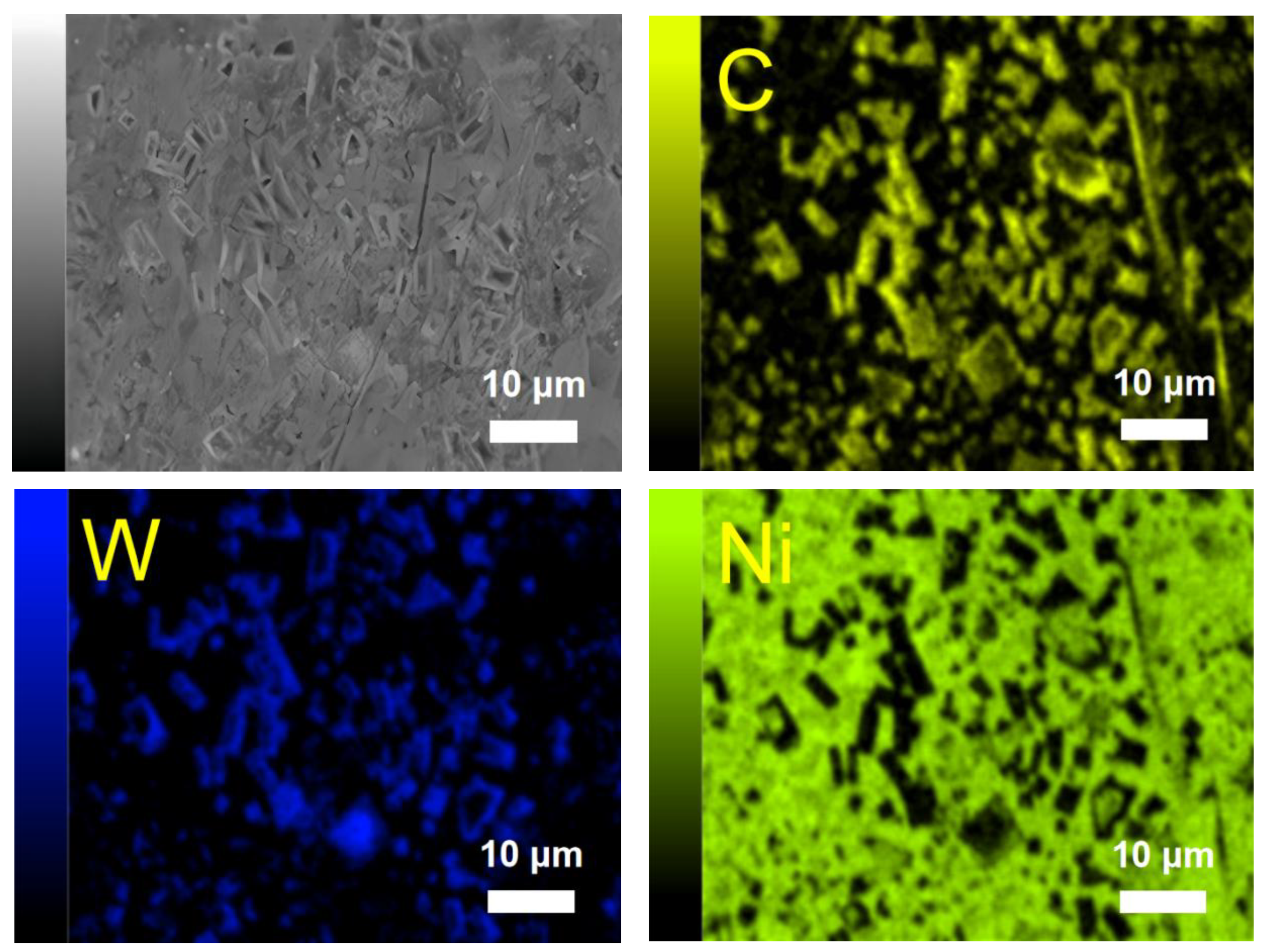
The microstructure of the upper and middle parts of the biomimetic unit was composed of equiaxed crystals and dendritic crystals, respectively. At a low WC content, coarse equiaxed grains and dendrites were formed. As the WC content increased, unmelted WC particles began to disperse throughout the entire melt pool. The WC particles acted as heterogeneous nucleation sites, promoting non-uniform nucleation and refining the grain size of the biomimetic units.
As the WC content increased, the hardness value continued to increase. When the WC content was 15%, the hardness range of the biomimetic unit was 777 HV0.2 to 912 HV0.2. When the WC content was 60%, the hardness range was 882 HV0.2 to 1008 HV0.2. The maximum hardness of each sample was observed in the subsurface layer of the biomimetic unit, and the hardness decreased sharply with increasing depth.
At a low WC content, the WC particles had little effect on the surface roughness. With the increase in the WC content, the viscosity of the melt pool increased, resulting in uneven cooling and solidification, thus increasing the surface roughness of the biomimetic unit.
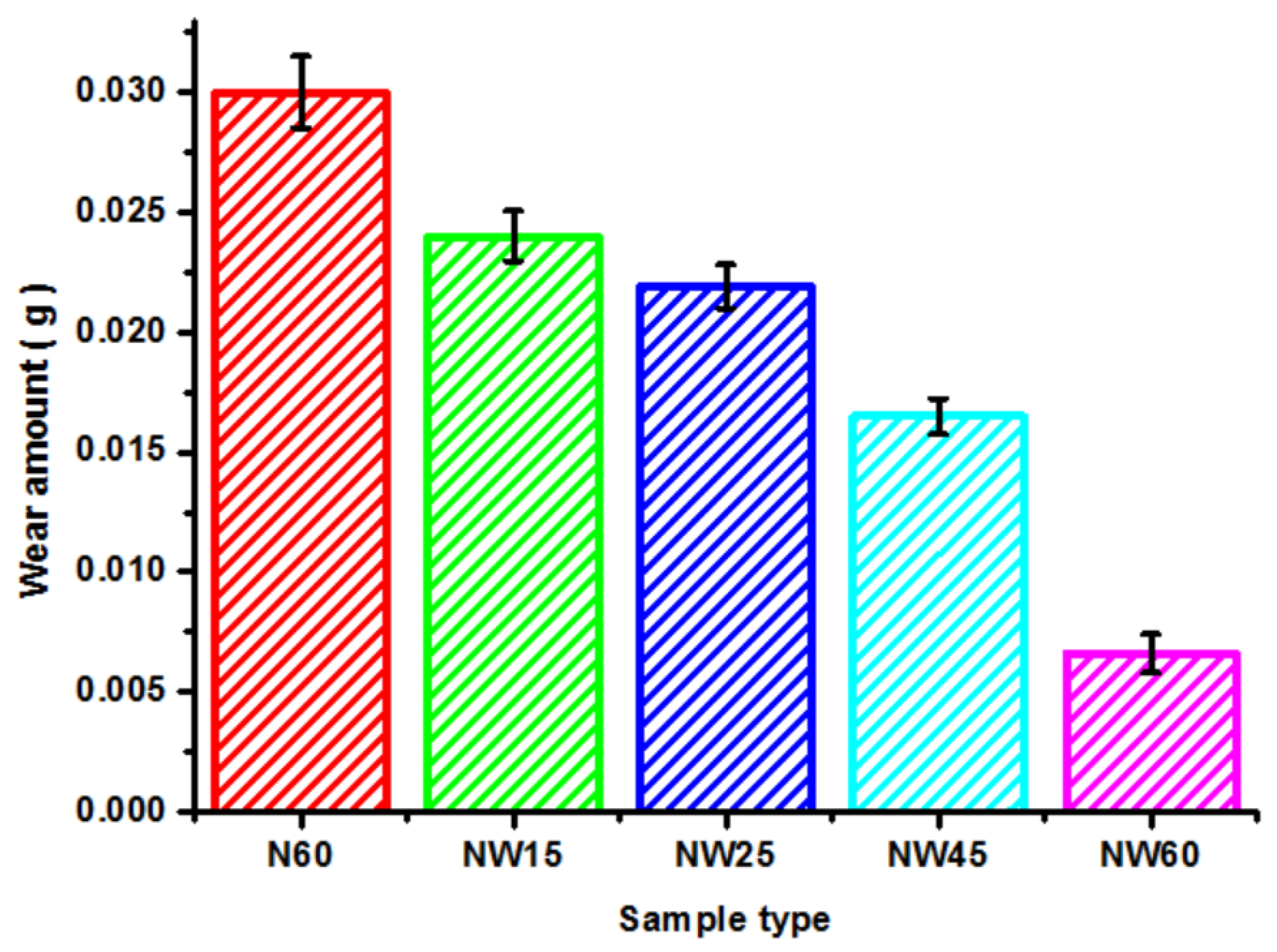
The wear mechanism of the N60 biomimetic unit was abrasive wear and oxidative wear. Adding WC to the nickel-based alloy powder changed the wear mechanism of the biomimetic units, namely, to adhesive wear, abrasive wear, and oxidative wear. As the WC content increased, the friction coefficient of the biomimetic unit initially showed a downward trend, followed by an upward trend. As the WC content increased, the hardness of the biomimetic unit increased, leading to a gradual reduction in wear. WC, as a hard phase, enhanced the strength and wear performance of biomimetic units.

Author Contributions

Methodology, B.C. and Y.L.; software, Z.S.; validation, Y.T.; data curation, Z.S. and Y.T.; writing—original draft, B.C.; writing—review and editing, Y.L. and B.C.; supervision, Z.S.; project administration, Y.L.; funding acquisition, Y.T. All authors have read and agreed to the published version of the manuscript.

Funding

This work was supported by the Natural Science Foundation of Jilin Province (Key Project of Free Exploration (Stable Support Project)) (No. YDZJ202401392ZYTS).

Data Availability Statement

The raw data supporting the conclusions of this article will be made available by the authors on request.

Conflicts of Interest

The authors declare no conflicts of interest.

References

  1. Reddy, G.; Madhu, S.; Prasad, C.D.; Kumar, B.K.P.; Sollapur, S.B. Investigation of hot corrosion behavior of plasma sprayed cermet composite coatings on titanium and special steel alloys. Surf. Coat. Technol. 2025, 499, 131883. [Google Scholar] [CrossRef]
  2. Alam, M.S.; Das, A.K. Surface morphological studies on hot corrosion behaviour of pre-oxidized plasma sprayed WC-CoCr coating on AISI316L steel in Na2SO4/NaCl molten salt environment. Phys. Scr. 2025, 100, 15943. [Google Scholar] [CrossRef]
  3. Mallick, R.; Kumar, R.; Panda, A.; Sahoo, A.K. A Novel Application of MgO Nano-cutting Fluid in Hardened AISI D2 Steel Machining Using a Chemical Vapor Deposition-Coated Carbide Tool. J. Mater. Eng. Perform. 2025, 34, 330–355. [Google Scholar] [CrossRef]
  4. Meysami, A.; Najafabadi, R.A.; Yosefnejad, T. Enhancing Wear Behavior and Hardness of D5 Cold Work Tool Steel through TiCrN Multilayer Nanocoating via Physical Vapor Deposition. Surf. Eng. Appl. Electrochem. 2024, 60, 58–68. [Google Scholar] [CrossRef]
  5. Locks, E.; He, Q.X.; Depaiva, J.M.; Guimaraes, M. Investigating the Impact of Physical Vapour Deposition (PVD)-Coated Cutting Tools on Stress Corrosion Cracking Susceptibility in Turning Super Duplex Stainless Steel. Coatings 2024, 14, 290. [Google Scholar] [CrossRef]
  6. Aktas, C.G.; Fountas, K.; Atapek, S.H.; Polat, S. Investigation of the Nitriding Effect on the Adhesion and Wear Behavior of CrN-, AlTiN-, and CrN/AlTiN-Coated X45CrMoV5-3-1 Tool Steel Formed Via Cathodic Arc Physical Vapor Deposition. Lubricants 2024, 12, 170. [Google Scholar] [CrossRef]
  7. Rafiei, J.; Ghasemi, A.R. Experimental Study of Stainless-Steel Nanoparticles Coating on Carbon Steel Using the Laser Cladding Approach. Mech. Compos. Mater. 2025, 60, 1183–1194. [Google Scholar] [CrossRef]
  8. Chen, X.; Wang, J.L.; Ke, D.W.; Wen, K. Numerical simulation and structure properties of laser clad 316 L stainless steel coating. Appl. Phys. A Mater. Sci. Process. 2025, 131, 111. [Google Scholar] [CrossRef]
  9. Zu, H.Y.; Liu, Y.P.; Chen, S.H.; Jin, X.; Ye, W.D. Forming Process Prediction Model and Application of Laser Cladding for Remanufactured Screw Pump Rotors. Materials 2025, 18, 1673. [Google Scholar] [CrossRef]
  10. Hu, K.X.; Huang, Q.Y.; Wang, L.; Zhou, Y.; Li, W.D. Optimization of multi-track, multi-layer laser cladding process parameters using Gaussian process regression and improved multi-objective particle swarm optimization. Int. J. Adv. Manuf. Technol. 2025, 137, 3503–3523. [Google Scholar] [CrossRef]
  11. Lu, D.; Cui, X.C.; Zhang, J.W. Microstructure and properties of high entropy alloy coating obtained by laser cladding. Sci. Rep. 2025, 15, 7357. [Google Scholar] [CrossRef] [PubMed]
  12. Liu, Z.B.; Han, C.H.; Cao, X.J.; Guo, J.; Li, H.X.; Lin, Y.J.; Yang, J. Microstructure and wear behavior of AISI 316L austenitic stainless steel coating fabricated by laser cladding and plasma nitriding. Mater. Lett. 2025, 383, 137951. [Google Scholar] [CrossRef]
  13. Wang, J.Y.; Cui, X.F.; Zhao, Y.; Zhang, Y.; Jin, G.; Feng, C.C. Microstructure and corrosion performance of Fe-based composite layer doped modification with Ti6Al4V fabricated by underwater wet laser cladding. Mater. Today Commun. 2025, 44, 111875. [Google Scholar] [CrossRef]
  14. Gan, R.; Liu, Z.D.; Kong, Y.; Chang, Y.R.; Shen, Y.; Li, J.X.; Ning, H.Q. Preparation and properties of Cu/Cu-Sn alloy cladding layers on titanium alloy by laser cladding. J. Alloy. Compd. 2025, 1020, 179547. [Google Scholar] [CrossRef]
  15. Xu, Y.H.; Wang, D.Z.; Wu, S.J.; Lu, H.X.; Yao, R.; Yang, J.; Jiang, F.; Takao, A. Research progress on defect formation mechanism and process optimization of laser cladding high entropy alloy coatings. Opt. Laser Technol. 2025, 187, 112819. [Google Scholar] [CrossRef]
  16. Hou, J.X.; Jin, X.W.; Xu, J.W.; Ding, K.J.; Liu, F.H.; Li, Z.X. Investigation on the influence of particle size on the microstructure and properties of laser-cladded CuSn12 coatings. J. Laser Appl. 2025, 37, 022017. [Google Scholar] [CrossRef]
  17. Sui, Q.; Zhou, H.; Yang, L.; Zhang, H.F.; Peng, L.; Zhang, P. Couple of biomimetic surfaces with different morphologies for remanufacturing nonuniform wear rail surface. Opt. Laser Technol. 2018, 99, 333–341. [Google Scholar] [CrossRef]
  18. Cong, D.L.; Li, Z.S.; He, Q.B.; Chen, D.J.; Chen, H.B. Effect of unit size on thermal fatigue behavior of hot work steel repaired by a biomimetic laser remelting process. Opt. Laser Technol. 2018, 98, 205–213. [Google Scholar] [CrossRef]
  19. Chuang, H.; Fan, W.; Liu, Z.C.; Kong, D.J. Effect of laser scanning speed on microstructure and corrosive-wear performance of Ni-60%WC coating in Wusu mine water. Ind. Lubr. Tribol. 2023, 75, 698–705. [Google Scholar] [CrossRef]
  20. Cao, Q.Z.; Fan, L.; Chen, H.Y.; Hou, Y.; Dong, L.H.; Ni, Z.W. Wear behavior of laser cladded WC-reinforced Ni-based coatings under low temperature. Tribol. Int. 2022, 176, 107939. [Google Scholar] [CrossRef]
  21. Wei, Y.C.; Feng, A.X.; Chen, C.L.; Shang, D.Z.; Pan, X.M.; Xue, J.J. Effects of Laser Remelting on Microstructure, Wear Resistance, and Impact Resistance of Laser-Clad Inconel625-Ni/WC Composite Coating on Cr12MoV Stee. Coatings 2023, 13, 1039. [Google Scholar] [CrossRef]
  22. Cao, Q.Z.; Fan, L.; Chen, H.Y.; Hou, Y.; Dong, L.H.; Ni, Z.W. Wear and corrosion mechanisms of Ni-WC coatings modified with different Y2O3 by laser cladding on AISI 4145H steel. Sci. Eng. Compos. Mater. 2022, 29, 364–377. [Google Scholar] [CrossRef]
  23. Wang, X.G.; Qi, J.J.; Zhang, H.; Zhao, N.; Shao, Z.B.; Wang, S.Y. Study on Wear and Corrosion Resistance of Ni60/WC Coating by Laser Cladding on Reciprocating Pump Plunger: Comparison with Flame-Sprayed Plungers. Materials 2024, 17, 5183. [Google Scholar] [CrossRef] [PubMed]
  24. Zhang, X.S.; Wang, Q.Y.; Deng, Y.H.; Chai, H.; Hu, S.Y. Effect of microstructure and micromechanics on wear/wear-corrosion mechanism of laser-repaired Ni-WC coating. Eng. Fail. Anal. 2024, 162, 108837. [Google Scholar] [CrossRef]
  25. Li, Y.F.; Shi, Y.; Tang, S.F.; Wu, J.X.; Zhang, W.Z.; Wang, J.S. Effect of nano-WC on wear and impact resistance of Ni-based multi-layer coating by laser cladding. Int. J. Adv. Manuf. Technol. 2023, 128, 4253–4268. [Google Scholar] [CrossRef]
  26. Li, C.G.; Zhang, Q.S.; Wang, F.F.; Deng, P.R.; Lu, Q.H. Microstructure and wear behaviors of WC-Ni coatings fabricated by laser cladding under high frequency micro-vibration. Appl. Surf. Sci. 2019, 485, 513–519. [Google Scholar] [CrossRef]
  27. Feng, M.J.; Ma, Y.H.; Tian, Y.T.; Cao, H.T. Microstructure and Wear Resistance of Ti6Al4V Titanium Alloy Laser-Clad Ni60/WC Composite Coating. Materials 2024, 17, 264. [Google Scholar] [CrossRef]
  28. Weng, Z.K.; Wang, A.H.; Wu, X.H.; Wang, Y.Y.; Yang, Z.X. Wear resistance of diode laser-clad Ni/WC composite coatings at different temperatures. Surf. Coat. Technol. 2016, 304, 283–292. [Google Scholar] [CrossRef]
  29. Liu, Y.; Xu, T.H.; Liu, Y.; Gao, Y.L.; Di, C. Wear and heat shock resistance of Ni-WC coating on mould copper plate fabricated by laser. J. Mater. Res. Technol-JMRT 2020, 9, 8283–8288. [Google Scholar] [CrossRef]
  30. Yang, H.S.; Li, W.; Liu, Y.C.; Li, F.X.; Yi, J.H.; Eckert, J. The Microstructure and Properties of Ni60/60% WC Wear-Resistant Coatings Prepared by Laser-Directed Energy Deposition. Micromachines 2024, 15, 1071. [Google Scholar] [CrossRef]
  31. Tao, L.; Yang, Y.; Zhu, W.L.; Sun, J.; Wu, J.L. Stress Distribution in Wear Analysis of Nano-Y2O3 Dispersion Strengthened Ni-Based μm-WC Composite Material Laser Coating. Materials 2024, 17, 121. [Google Scholar] [CrossRef]
  32. Liu, Y.; Xu, T.H.; Li, G.H. Research on Wear and Corrosion Resistance of Ni60-WC Coating Fabricated by Laser on the Preheated Copper Alloy. Coatings 2022, 12, 1537. [Google Scholar] [CrossRef]
  33. Wu, X.Q.; Zhang, D.D.; Hu, Z. Microstructure and Wear Properties of Laser Cladding WC/Ni-Based Composite Layer on Al-Si Alloy. Materials 2021, 14, 5288. [Google Scholar] [CrossRef] [PubMed]
  34. Xu, J.S.; Zhang, X.C.; Xuan, F.Z.; Wang, Z.D.; Tu, S.T. Microstructure and Sliding Wear Resistance of Laser Cladded WC/Ni Composite Coatings with Different Contents of WC Particle. J. Mater. Eng. Perform. 2012, 21, 1904–1911. [Google Scholar] [CrossRef]
  35. Guo, C.; Zhou, J.S.; Chen, J.M.; Zhao, J.R.; Yu, Y.J.; Zhou, H.D. High temperature wear resistance of laser cladding NiCrBSi and NiCrBSi/WC-Ni composite coatings. Wear 2011, 270, 492–498. [Google Scholar] [CrossRef]
  36. Bao, Y.C.; Deng, J.X.; Cao, S.H.; Wang, J.Y.; Zhang, Z.H.; Lu, Y. High temperature wear performance of in-situ forming textured Ni60/WC/h-BN composite coatings based on laser micro-cladding. J. Mater. Res. Technol-JMRT 2024, 33, 3470–3481. [Google Scholar] [CrossRef]
  37. Chen, C.L.; Feng, A.X.; Wei, Y.C.; Wang, Y.; Pan, X.M.; Song, X.Y. Effects of WC particles on microstructure and wear behavior of laser cladding Ni60 composite coatings. Opt. Laser Technol. 2023, 163, 109425. [Google Scholar] [CrossRef]
  38. Guo, C.; Chen, J.M.; Zhou, J.S.; Zhao, J.R.; Wang, L.Q. Effects of WC-Ni content on microstructure and wear resistance of laser cladding Ni-based alloys coating. Surf. Coat. Technol. 2012, 206, 2064–2071. [Google Scholar] [CrossRef]
  39. Zhao, T.; Cai, X.; Wang, S.X.; Zheng, S. Effect of CeO2 on microstructure and corrosive wear behavior of laser-cladded Ni/WC coating. Thin Solid Films 2000, 379, 128–132. [Google Scholar]
  40. Zhao, N.; Tao, L.; Guo, H.; Zhang, M.Q. Effect of Ultra-fine WC Particles on Microstructural Evolution and Wear Behavior of Ni-Based Nano-CeO2 Coatings Produced by Laser. Rare Metal Mat. Eng. 2018, 47, 20–25. [Google Scholar]
  41. Zhu, Y.Q.; Shen, S.K.; Yang, X.F.; Song, F.; Dong, W.L.; Wang, Z.Y.; Wu, M. Study on the friction and wear performance of laser cladding WC-TiC/Ni60 coating on the working face of shield bobbing cutter. Opt. Mater. 2024, 148, 114875. [Google Scholar] [CrossRef]
  42. Farahmand, P.; Kovacevic, R. Corrosion and wear behavior of laser cladded Ni-WC coatings. Surf. Coat. Technol. 2015, 276, 112–135. [Google Scholar] [CrossRef]
  43. Huang, S.W.; Samandi, M.; Brandt, A. Abrasive wear performance and microstructure of laser clad WC/Ni layers. Wear 2004, 256, 1095–1105. [Google Scholar] [CrossRef]
  44. Wang, J.; Zhang, X.Q.; Qiao, L.; Zhao, Y.; Ren, M.F.; Li, T.T.; Li, R.F. A Comprehensive Study on Microstructure and Wear Behavior of Nano-WC Reinforced Ni60 Laser Coating on 17-4PH Stainless Steel. Coatings 2024, 14, 484. [Google Scholar] [CrossRef]
Figure 1. Schematic diagram of block-on-ring tribometer and biomimetic unit.
Metals 15 00507 g001
Figure 2. Cross section of biomimetic unit: (a) surface morphology of biomimetic unit of NW60 sample; (b) height and width of each sample.
Metals 15 00507 g002
Figure 3. Longitudinal section of biomimetic unit: (a) NW15 sample; (b) NW25 sample; (c) NW45 sample; (d) NW60 sample.
Metals 15 00507 g003
Figure 4. Microstructure of each sample: (a) upper region of NW15 sample; (b) middle region of NW15 sample; (c) upper region of N60 sample; (d) upper region of NW25 sample; (e) upper region of NW60 sample; (f) middle region of NW60 sample.
Metals 15 00507 g004
Figure 5. XRD patterns of each sample.
Metals 15 00507 g005
Figure 6. EDS point scan results of chemical elements in NW25 sample.
Metals 15 00507 g006aMetals 15 00507 g006b
Figure 7. EDS chemical element surface scan of NW25 sample.
Metals 15 00507 g007aMetals 15 00507 g007b
Figure 8. Hardness curves of various biomimetic units.
Metals 15 00507 g008
Figure 9. Worn morphology of samples: (a) N60 sample; (b) NW15 sample; (c) NW45 sample; (d) NW60 sample.
Metals 15 00507 g009
Figure 10. EDS surface scan of worn surface of NW45 sample.
Metals 15 00507 g010
Figure 11. EDS surface scan of exposed WC on NW45 sample surface.
Metals 15 00507 g011
Figure 12. The friction coefficient of each sample.
Metals 15 00507 g012
Figure 13. The wear amount of each sample.
Metals 15 00507 g013
Table 1. Chemical composition of substrate and powder.
Element (Wt.%)CBSiCrMnNiFeTiW
20CrMnTi0.17–0.23-1.00–1.300.17–0.370.80–1.10-Bal0.04–
0.10
-
Ni600.5–1.13–4.53.5–5.512–
20
-Bal≤5--
WC3.9-0.01180.0067--0.110.0008Bal
Table 2. Processing parameters and sample number.
Sample Number
Parameters
Laser Power
(kW)
Scanning Speed
(mm/min)
Wavelength (nm)Spot Radius (mm)Powder Delivery Rate (g/min)Ni60 Content
(Wt.%)
WC Content (Wt.%)
N602.025010704121000
NW158515
NW257525
NW455545
NW604060
Table 3. Chemical element content at each sampling point.
Sampling Point
Mass Fraction of Element (%)
CSiCrMnFeNiWSr
Point 12.331.282.980.4177.3715.72--
Point 22.98-5.490.3956.237.6227.29-
Point 32.442.182.690.3772.4415.55-4.33
Point 42.54-4.340.4673.9618.70--
Table 4. Surface roughness of each sample.
Sample Number
Type of Roughness
Ra (μm)Rz (μm)Rt (μm)Rp (μm)Rq (μm)
N600.653.59516.1826.260.796
NW151.0024.61129.11315.2081.197
NW251.2946.66513.8645.1951.586
NW451.5148.25243.52331.4171.958
NW601.8178.29847.27321.2912.138
Disclaimer/Publisher’s Note: The statements, opinions and data contained in all publications are solely those of the individual author(s) and contributor(s) and not of MDPI and/or the editor(s). MDPI and/or the editor(s) disclaim responsibility for any injury to people or property resulting from any ideas, methods, instructions or products referred to in the content.

