Article

The Role of Si Element on the Precipitation Behavior of GH2907 Superalloys

1
Key Laboratory for Light-Weight Materials, Nanjing Tech University, Nanjing 210009, China
2
Paike New Materials Co., Ltd., Wuxi 214161, China
*
Author to whom correspondence should be addressed.
Metals 2025, 15(5), 484; https://doi.org/10.3390/met15050484
Submission received: 23 March 2025 / Revised: 12 April 2025 / Accepted: 22 April 2025 / Published: 25 April 2025

Abstract

GH2097, a Fe-Ni-Co-based superalloy extensively employed in high-temperature critical components such as aircraft engines, was investigated to elucidate the influence of Si content on its precipitation behavior and mechanical properties. By systematically adjusting Si concentrations, it was demonstrated that Si significantly modulates the size, distribution, and stability of γ′ phase (Ni3TiNb). As Si content increases, γ′ phase coarsening (mean size: 30.1→40.3 nm) results in a marginal increase in volume fraction of 2%. Mechanical testing revealed a direct correlation between Si content and yield strength enhancement, achieving a maximum increment of 97.1 MPa. Post solution-aging treatment, γ′ strengthening dominated the strengthening mechanisms in GH2097, contributing over 50% to the overall strength. Microstructural characterization (SEM/TEM) further confirmed that optimal Si addition balances precipitation kinetics and grain boundary stabilization without inducing detrimental phases. Therefore, it is important to consider the role of the Si element in the microstructure control of GH2907 alloy.

1. Introduction

As the core material of modern aero-engines, gas turbines, and other extreme environment equipment, the performance of superalloy directly determines the thrust-to-weight ratio, thermal efficiency, and service life of the equipment. The GH2907 alloy, based on Fe-Ni-Co, is widely used in key hot-end components such as turbine discs and combustion chamber bushings due to its excellent high temperature strength, oxidation resistance, and long-term structure stability [1,2,3,4]. However, with the continuous increase in aero engine operating temperature, traditional superalloys are faced with severe challenges: on the one hand, the coarring of the γ′ strengthening phase causes a sudden decline in strength under high temperature; on the other hand, the problems of creep fracture and thermal corrosion caused by grain boundary weakening are significantly aggravated. To deal with this dilemma, microalloying strategy has become the core direction of material design, namely through the introduction of trace alloying elements to regulate the precipitated phase behavior and optimize the grain boundary structure, so as to achieve multistage strengthening at the nanometer to micron scale [5,6].
The GH2907 alloy features three primary precipitation phases: the nanoscale γ′ phase, the needle-like ε phase, and the coarse Laves phase [7]. The γ′ phase serves as the primary reinforcing phase in the alloy, comprising approximately 15.2% of its composition, with a precipitation peak around 630 °C. It shares the same face-centered cubic (fcc) structure as the matrix, maintaining a coherent lattice relationship. This phase precipitates uniformly within the matrix as rounded or cubic particles, contributing to the alloy’s excellent transient strength properties [8,9]. The crystal structure of the ε phase in this alloy remains somewhat controversial [2,10,11]. A sufficient amount of ε phase is crucial in GH2907 alloy to alleviate notch sensitivity. However, excessive precipitation of the ε phase can deplete the strengthening γ′ phase, resulting in a reduction in the alloy’s ultimate tensile strength [12]. Therefore, achieving a balance between the amounts of ε phase and γ′ phase precipitation is essential for the material to attain both high transient strength and good durability. Another important phase in the alloy is the Laves phase, which precipitates in the temperature range from 800 °C to 1040 °C. This phase plays a crucial role in controlling grain size [13,14].
Generally, the types and morphologies of the precipitated phases in GH2907 alloy are closely related to the content of trace elements, the heat treatment process, and other influencing factors [15]. Despite its low concentration, ranging from 0.07% to 0.35% (wt.%), silicon plays a pivotal role in GH2907 alloy, as all three primary precipitation phases exhibit a notable Si-rich composition [16,17]. To achieve a low coefficient of expansion, the alloy is deficient in chromium, which leads to reduced oxidation resistance. Regarding the effect of trace silicon on the microstructure and mechanical properties of alloys, there have been several reports both domestically and internationally [10,18]. However, the specific mechanisms by which silicon influences these properties still require further investigation. The relationship between Si content and γ′ phase coarsening has been established in this paper, which provides a theoretical tool for predicting long-term microstructure stability of superalloys [19]. The influence of Si on strength was investigated. The contribution degree of γ′ phase strengthening, grain boundary strengthening, and solid solution strengthening was quantitatively analyzed to clarify the weight distribution of Si in the multi-level strengthening mechanism.
In summary, the investigation of the types of precipitated phases and their evolution in GH2907 alloy remains controversial, yet the characterization of this evolution is vital for understanding the alloy’s mechanical properties. In this work, various observation and phase analysis techniques are employed to study the evolution of precipitated phases in GH2907 alloy throughout different stages of the heat treatment process. The aim is to elucidate the relationships between these phases and their roles, thereby providing theoretical references for the microstructural control of GH2907 alloy.

2. Experimental Section

To compare the effect of silicon content on the properties of GH2907 alloy, two materials, alloy I and alloy II, which were forged with different Si content, were selected for testing. The chemical compositions of these alloys are presented in Table 1. To clarify the organizational characteristics of GH2907 alloy and the evolution of its microstructure during the heat treatment process, a step-by-step heat treatment was conducted based on the GH2907 alloy heat treatment system. The specific heat treatment processes and corresponding sample numbers are outlined in Table 2. Here, AC denotes air cooling and FC denotes furnace cooling.
The microstructural observations of the specimens were conducted using a TESCAN CLARA field emission scanning electron microscope (SEM), manufactured in the Brno, Czech Republic. The surface treatment method for the samples involved sequential grinding with 180#, 600#, 800#, 1500#, and 2000# sandpaper, followed by mechanical polishing using diamond polishing pastes with particle sizes of 3 μm, 1 μm, and 0.5 μm. Finally, the samples were etched using a mixed solution of 3 g CuCl2, 50 mL HCl, 50 mL C2H5OH, and 50 mL H2O. The size and volume fraction of Laves and γ′ phases were measured using Photoshop2023(v24.7) and ImageJ 2 (2.14.0) software. The electron backscatter diffraction (EBSD) samples were mechanically polished, followed by electrolytic polishing. The electrolytic polishing solution was 90% anhydrous ethanol and 10% perchloric acid (volume ratio), the voltage was 20 V, the current was about 0.8 A, and the polishing time was about 20–30 s. EBSD observations were performed on a TESCAN CLARA field emission gun scanning electron microscope (FEG-SEM) equipped with the TSL OIM™ EBSD system with a scanning step of 0.8 μm. An orientation deviation threshold of 15° was used to differentiate between low-angle boundaries (LAB) and high-angle boundaries (HAB). The samples for transmission electron microscopy (TEM) and scanning transmission electron microscopy (STEM) were mechanically polished and ion-thinned employing a Gatan Precision Ion Polishing System (PIPS 691) in the California, USA. The TEM (JEOL, Tokyo, Japan, JEM-F200), operated at 200 kV, was used to investigate the microstructure evolution. The TESCAN MIRA field emission scanning electron microscope with scanning transmission probe was used in this experiment. The working voltage was 30 kV, and the working distance was 5 mm.
Tensile tests were performed using the Instron 5500R uniaxial tensile testing machine at a strain rate of 0.001 s−1 in the Boston, USA. All the tensile specimens were plates with a gage length of 60 mm, a width of 5 mm, and a thickness of 2 mm. The tensile test of each group was carried out at least three times to ensure reproducibility.

3. Results

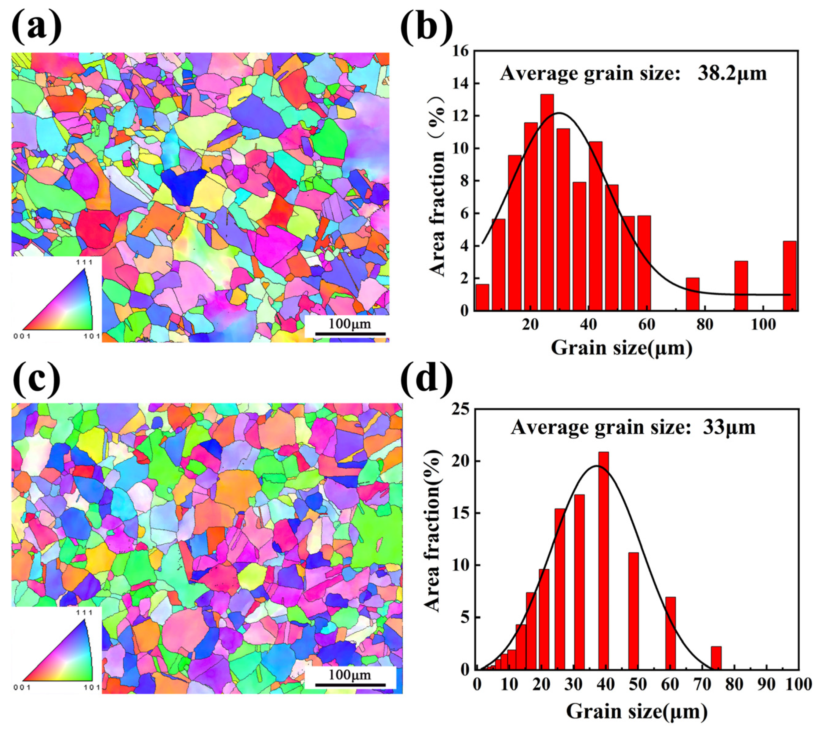
3.1. As-Forged Microstructures

Figure 1 illustrates the EBSD inverse pole figure maps of the as-forged GH2907 alloys. It can be seen that the two alloys both exhibit equiaxed grains and random orientation distributions. The average grain size of Alloy I and Alloy II is 38.2 μm and 33 μm, respectively. Notably, there are some coarse grains present in Alloy I. The largest grain reached a size of 109.1 μm. Approximately 7.2% of the grains of Alloy I exceed 80 μm in size, indicating a heterogeneous grain structure.
To further clarify the types and distribution of precipitated phases in the as-forged GH2907 alloy, TEM observations were conducted. The results are presented in Figure 2 and Figure 3. Figure 2 shows the morphology of the Laves phase in the as-forged samples. The selected area electron diffraction (SAED) pattern confirms that the crystal structure is of the MgZn2 type. The Laves phase in GH2907 alloy is highly stable, persisting even at solution temperatures as high as 1080 °C without fully dissolving. Its primary role is to inhibit grain growth [20,21]. The influences of the Laves phase on the microstructures and mechanical properties will be discussed below. Nanoscale spherical γ′ phases were observed in both alloys (as shown in Figure 3). The SAED patterns confirm that the crystal structure is of the L12 type (as shown in Figure 3b,d). The γ′ phase size of Alloy I is approximately 5 nm, while that of Alloy II is ~8 nm.

3.2. Microstructural Evolution During Various Heat Treatments

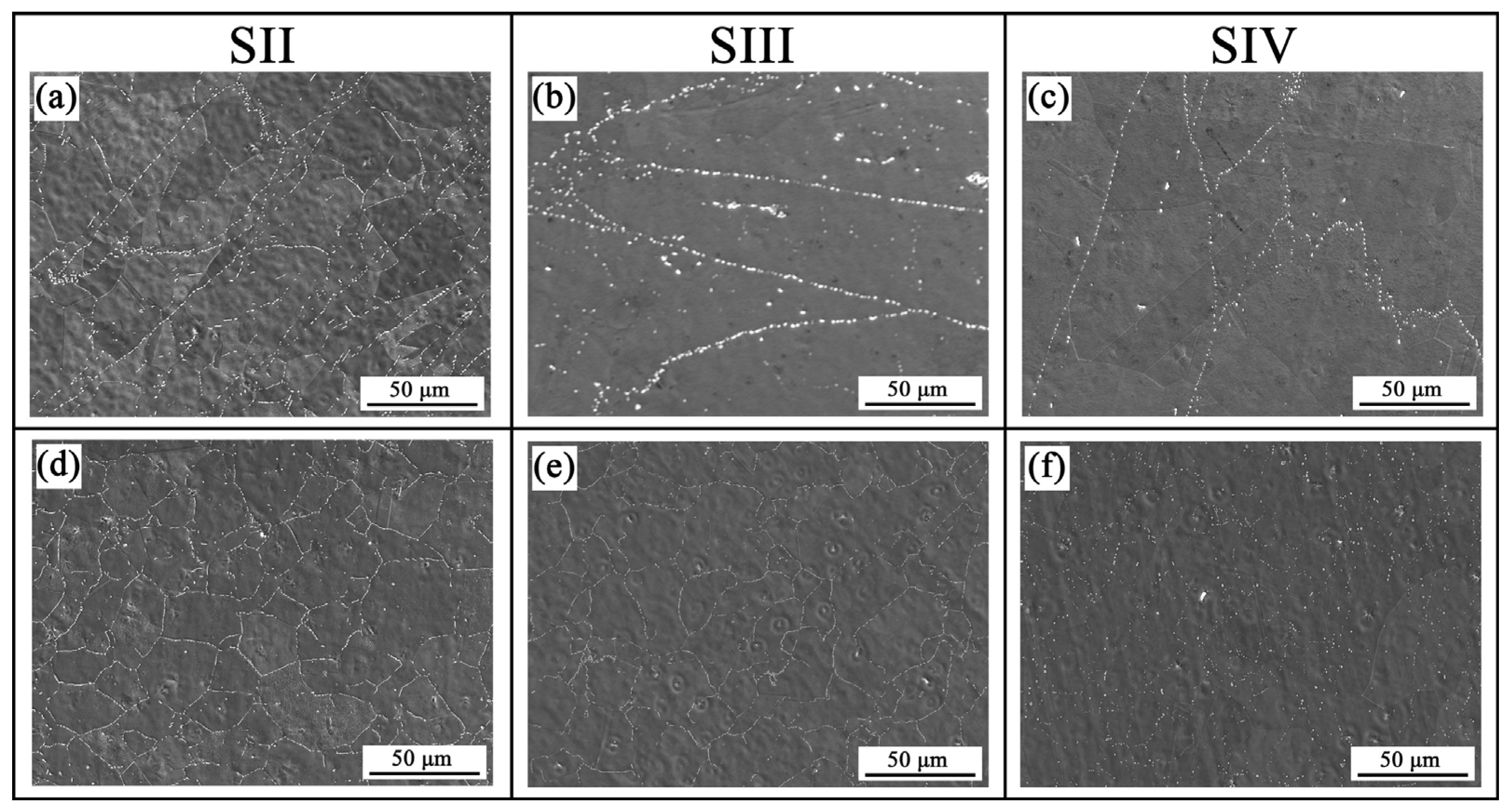
3.2.1. The Effects of Solution Treatment

Figure 4 shows the microstructures of the samples subjected to various solution temperatures of 980 °C, 990 °C, and 1000 °C. After the solution treatments, the Laves phase in both Alloy I and Alloy II remains, while the ε phase is invisible. The remaining Laves phase of Alloy I is diffusely distributed (as shown in Figure 4a–c), while that of Alloy II exists along grain boundaries (as shown in Figure 4d–f). The volume fractions of the Laves phase of the Alloy I solution at 980 °C, 990 °C, and 1000 °C were 3.0%, 1.9%, and 0.8%, whereas those of Alloy II subjected to the corresponding solution treatment were 3.2%, 2.8%, and 1.1%, respectively. This indicates that the Laves phase dissolves as the solution temperature increases. Even with the solution temperature rising to 1000 °C, the Laves phase still does not fully dissolve into the matrix. The average grain sizes of the Alloy I solution at 980 °C, 990 °C, and 1000 °C are 42.6 μm, 58.5 μm, and 73.2 μm, while those of Alloy II subjected to the corresponding solution treatment are 29.6 μm, 35.2 μm, and 59.1 μm. This reveals that as the solution temperature increases, the grains gradually coarsen. The existence of the Laves phase in Alloy II restricts the growth of grains.

3.2.2. The Effects of Aging Treatment

Figure 5 shows the back-scattered electron (BSE) images of the samples subjected to solution at 980 °C and two-stage aging treatment. Besides the short rod-shaped Laves phase, needle-like ε phases are observed in both Alloy I and Alloy II. The distribution of the Laves phase is consistent with that of the solid solution state. The Laves phase of alloy I is diffusively distributed, while the Laves phase of Alloy II is distributed along the grain boundaries.
The TEM images of the ε phase in the solution aging treatment condition are shown in Figure 6. The ε phase is a disk-like precipitation phase with an ordered superlattice structure. Excessive precipitation of the ε phase consumes the main strengthening phase γ′, which is detrimental to the strength of the alloy. Figure 7 shows STEM images of the γ′ phase in the samples subjected to solution at 980 °C and two-stage aging treatment. The images (Figure 7a,b) reveal distinct differences in the γ′ phase sizes between the two alloys despite being subjected to identical heat treatment conditions. In Alloy I, the γ′ phase has an average size of approximately 30 nm, while in Alloy II, it is larger, with an average size of about 40 nm. The γ′ phases are characterized by their substantial presence and relatively fine size, consistent with findings in previous studies [22]. Further TEM SAED pattern analysis reveals the orientation relationship of [011]γ//[011]γ′ between the γ matrix and γ′ precipitate, as shown in Figure 8c. According to the high-resolution TEM images in Figure 8e–f, the lattice parameters of γ matrix and γ′ precipitates are 0.5043 nm and 0.5034 nm, respectively, revealing that the γ/γ′ interface is coherent.
It is worth noting that γ′ phase depletion zones are observed at critical interfaces within the microstructure, specifically between the γ′/Laves interface and the γ′/ε interface. These depletion zones are indicative of localized compositional changes and microstructural interactions during the alloy’s thermal and mechanical processing. The depletion zones likely result from diffusion processes, where key alloying elements such as Ni, Nb, or Ti, which are essential for γ′ phase formation, are consumed or redistributed near these interfaces. Figure 9 shows the HAADF results of Alloy II subjected to solution and two-stage aging treatment. It is evident that all three types of precipitated phases (γ′, Laves phase, and ε phase) are enriched with Ni, Nb, and Ti. This elemental distribution highlights the critical role of these alloying elements in the formation and stabilization of the phases. In the Laves phase, a significant enrichment of Si is observed. This elemental accumulation highlights the role of Si in the formation and stabilization of the Laves phase.

3.3. Mechanical Properties

Figure 10 shows the engineering stress–strain curve and the work hardening rate vs. true strain curve at the solution aging treatment state. The yield strength, ultimate tensile strength, uniform elongation, and fracture elongation of Alloy I and Alloy II are summarized in Table 3. From Figure 10 and Table 3, it can be seen that the ultimate tensile strength and yield strength of Alloy II are higher than those of Alloy I. Specifically, Alloy II exhibits a yield strength of 987.4 MPa, which is 97.1 MPa greater than the yield strength of Alloy I at 890.3 MPa. Similarly, the ultimate tensile strength of Alloy II is superior to Alloy I, indicating that Alloy II has a higher capacity to withstand stress before failure. The uniform and fracture elongation of Alloy II is smaller than those of Alloy I, indicating that Alloy II has lower ductility compared to Alloy I.

3.4. Fracture Analysis

In order to analyze the tensile fracture behavior of the samples after solution ageing, the tensile fracture surfaces were observed, as shown in Figure 11. More or less ductile cupping and conical damage were found throughout the fracture surface. The fracture morphology shows that the specimen presents a ductile fracture. As shown in Figure 11a,c, microcracks appear along the grain boundaries. Alloy II has many pits, while Alloy I has relatively flat pits. Although there is no significant necking between the two Alloy fractures, the surface of Alloy I exhibits a dimple fracture pattern at higher magnification (Figure 11b), whereas Alloy II has fewer dimples.

4. Discussion

4.1. Precipitation Behavior

As described above, the nanoscale γ′ phase, the needle-like ε phase, and the coarse Laves phase are the key precipitation phases, influencing the alloy’s strength and ductility. In the as-forged GH2907 alloy, the primary precipitation phases are the γ′ phase and the Laves phase, with no evidence of the needle-like ε phase. The Laves phase exhibited exceptional stability and could not be fully dissolved, even when the solution treatment temperature was increased to 1080 °C.
The Laves phase was extremely stable and could not be completely recompacted even when the solid solution temperature was increased to 1080 °C. The Laves phase was not completely recompacted after solid solution treatment. Figure 4 shows the morphology and distribution of the Laves phase under solid solution treatment, and the short bars were not completely recompacted after solid solution treatment, and no ε phase precipitation was found.
In heat treatment, grain refinement is achieved by controlling the number and distribution of Laves. A sufficient Laves phase must be precipitated to allow grain boundary pinning; however, very coarse Laves phase particles reduce the grain refinement effect [23]. It can be seen in Figure 4 that in Alloy I, the Laves phase is diffusely distributed within the grain boundaries (Figure 4a–c), while in Alloy II, the Laves phase is distributed along the grain (Figure 4d–f). The grain size of GH2907 alloy is not only related to the distribution of Laves phase, but also to its precipitation quantity. At different solid solution temperatures, the Laves phase precipitation also changes. As shown in Figure 4, the Laves phase distribution did not change with increasing solid solution temperature; however, the amount of precipitation changed. The Laves phase share was counted using ImageJ 2 (2.14.0) commercial software, and the results showed that as the solid solution temperature increases, the Laves phase precipitation decreases and the grains begin to grow. In order to control the grain size, attention should be paid to the Laves phase distribution and the amount of precipitation. The distribution is independent of the solid solution temperature and is related to the forging process. A reasonable solid solution temperature should be controlled in heat treatment; if it is too high, it will lead to a decrease in Laves phase precipitation, and the grain size will be too large. If it is too low, it will lead to an increase in Laves phase precipitation and a decrease in other phase precipitation after consuming a large amount of Nb.
The ε phase has good toughness, can absorb a large amount of energy in the form of plastic deformation, improve the coordination of deformation within the crystal and grain boundaries, and effectively prevent the expansion of cracks [15]; therefore, the morphology, content, distribution, and other factors of the ε phase in the GH2907 alloy play a key role in the mechanical properties of the alloy. However, the ε phase is also not a very stable phase, as with time and temperature, the phase can transform into a honeycomb, tightly packed η-type phase.
The excellent performance of nickel-based high-temperature alloys mainly comes from the solid solution strengthening of the FCC-γ matrix itself and the precipitation strengthening of the L12-γ′ ordered phase. At high temperatures, the γ′ phase of the L12 structure impedes the movement of dislocations by forming antiphase domain boundaries and locking the dislocations. Especially when the volume fraction of the γ′ phase is greater than 60%, the overall high-temperature creep performance of the alloys and their components has been significantly improved [22,24].
The addition of Si to the alloy significantly affects the formation of these phases during processing, thus affecting the mechanical properties [25]. The influence of Si on the morphology and quantity of precipitated phase is achieved by changing the thermodynamics and dynamics of nucleation and growth of the second phase with the change of Si content. First, Si affects the stability of parent austenite. With the increase in Si content, the stability of the alloy matrix and γ′ decreases, and the precipitation of ε and Laves phases is promoted. Secondly, the enrichment of Si at grain boundaries creates favorable conditions for the nucleation and growth of the second phase. Si is a surface active element, and adsorption on the grain boundary or the second phase surface can reduce the interface energy. The grain boundary is the most ideal nucleation site of the second phase. In grain boundary nucleation, the influence of strain energy can be ignored; only the surface energy barrier can be overcome. The diffusion of Si in iron must be carried out by displacement. Grain boundary and ε-phase boundary are the most favorable diffusion paths for Si atoms. Therefore, there will be enrichment of Si on the surface of the phase, which can reduce its surface energy [25].

4.2. Effect of the Precipitation on the Mechanical Properties

Understanding the precipitation-strengthening mechanism is critical for correlating microstructural evolution with the alloy’s yield strength. The low-expansion superalloy GH2907 belongs to the precipitated phase-strengthened alloy, whose strengthening mechanism is that the precipitated γ′ phase interacts with the dislocations and hinders their movement of the dislocations [26], which improves the deformation resistance of the alloy [27,28]. Equation (1) provides a generalized framework for calculating the yield strength of γ′-strengthened Ni superalloys, accounting for their characteristic deformation behavior [29,30].
σ Y S = σ o + Δ σ G B + Δ σ s s + Δ σ D i s + Δ σ γ + Δ σ O r o w a n
where σ o is the friction stress, and σ o (37.0 MPa) of pure Ni [31] is used in this study. The strength enhancement of the material arises from multiple mechanisms, including grain boundary interactions (denoted as Δ σ G B ,), solute atom effects ( Δ σ s s ), dislocation accumulation ( Δ σ D i s ,), γ′ phase precipitation ( Δ σ γ ), and the Orowan bypass mechanism ( Δ σ O r o w a n ).
The strength contribution from grain boundary strengthening adheres to the Hall–Petch equation as follows:
σ G B = k y d m
where k y is the Hall–Petch constant, which in Ni-based superalloys is generally 422.0 MPa/μm1/2 [32], and d m is the average grain size. The average grain sizes of Alloy I and Alloy II in the heat-treated state (SIII) were 35.7 μm and 27.4 μm. The grain boundary strengthening components were quantified at 50.1 MPa and 54.3 MPa. Subsequent analysis of solid solution effects followed the concentration-dependent formulation as follows [31,33]:
σ s s = ( k i 1 n c i ) n
Here, k i represents the contribution factor of an alloying element to material strengthening, while C i corresponds to its atomic concentration within the matrix, respectively. n is a constant (0.5 [31]). The major solution elements in the experimental alloy are Nb, Ti, and Si, and the corresponding value of k i is 1183, 775, and 275 MPa at%−0.5, respectively [34]. The measured values of C i for Nb, Ti, and Si are 2.4%, 1.3%, and 0.2% for Alloy I and 2.4%, 1.4%, and 0.3% for Alloy II. σ S S of Alloy I and Alloy II were calculated as 197.0 MPa and 199.5 MPa, respectively. Another strengthening mechanism, dislocation strengthening, can be expressed using Taylor’s equation [35] as follows:
σ D i s = M a G b ρ
The dislocation strengthening contribution ( σ D i s ) was calculated using the Taylor-based formulation with parameters: Taylor factor M = 3.06 [36], scaling constant a = 0.24 [37], shear modulus G = 85.3 GPa [38], Burgers vector b = 0.25, and dislocation densities ρ = 1.28 × 10¹⁴ m−2 (Alloy I)/1.77 × 1014 m−2 (Alloy II) measured via GND density mapping, yielding σ D i s values of 106.5 MPa and 133.8 MPa, respectively.
The precipitation of nanoscale γ′ phases (average size ~20 nm) effectively enhances alloy strength through dislocation shearing mechanisms, while concurrently inducing plasticity reduction. This γ′-mediated strengthening, dependent on precipitate dimensions [39], primarily originates from the three following synergistic effects: coherent lattice strain, elastic modulus mismatch, and antiphase boundary energy elevation during ordered phase cutting [40], as follows:
σ C S = M × a ε ( G ε c ) 3 2 ( r f 0.5 G b ) 1 / 2
σ M S = M × 0.0055 ( Δ G ) 3 2 ( 2 f G ) 1 2 ( r b ) 3 w 2 1
σ O S = M × 0.81 γ A P B 2 b ( 3 π f 8 ) 1 / 2
The strengthening parameters include the following: Taylor factor M = 3.06 (FCC structure structure [41]), constant a ε = 2.06 (FCC metals [41]), γ/γ′ lattice misfit ε =   ( 2 / 3 ) ( Δ a / a ) with (where a γ = 0.5043 nm, a γ , = 0.5043 nm), γ′ precipitate radius r = 30.1 nm (Alloy I)/40.3 nm (Alloy II), and γ′ volume fraction f = 15% (Alloy I)/17% (Alloy II) [42]. Δ G is the shear modulus misfit between γ and γ′ (90.2 GPa for γ′ phases [43]), w is a constant (0.85 [42]), and γ A P B is the anti-phase boundary energy of γ′ phases (0.12 J/m2 [42]). After calculation, the increases in YS induced by coherency strengthening, modulus strengthening, and ordering strengthening are 31.8 MPa, 204.6 MPa, and 236.1 MPa for Alloy I and 39.1 MPa, 237.5 MPa, and 252.1 MPa for Alloy II, respectively. Δ σ γ was calculated as 472.4 MPa and 528.7 MPa.
The yield strength enhancement induced by Laves phase precipitation can be quantified through the following Orowan bypass mechanism [44]:
Δ σ O r o w a n = G b 4 π L ( 1 + 1 1 + v ) l n L 2 b
L = r ( 2 π 3 f π 2 ) 1 / 2
The Orowan strengthening contributions were calculated using the following key parameters: Burgers vector b = 0.254 nm [45], Poisson’s ratio v = 0.15 [45], shear modulus G = 75.81 GPa, particle volume fraction f (experimentally determined), mean spacing L , and particle dimension r , yielding values of 29 MPa (Alloy I) and 35 MPa (Alloy II).
The yield strengths of Alloy I and Alloy II were estimated to be 898.2 MPa and 990.3 MPa, respectively, using the parameters of six strengthening mechanisms of the two alloys, which were similar to the actual yield strengths. Figure 12 demonstrates the consistency between cumulative contributions from various strengthening mechanisms and experimentally determined strength values, revealing that γ′ precipitation strengthening predominantly governs the exceptionally high yield strength (53% and 54% proportional contributions in Alloy I and Alloy II, respectively).
The addition of Si significantly affects the nucleation and coarsening kinetics of γ′ phase in the process of solution-aging heat treatment. The results show that with the increase in Si content, the average size of the γ′ phase coarsened from 30.1 nm to 40.3 nm, the volume fraction increased from 15.2% to 17.1%, and the yield strength increased by 97.1 MPa. The Si content should be controlled at 0.3 wt.% to achieve optimal performance, and the γ′ phase size and volume fraction match best in this range. At the same time, the grain boundary precipitated phase can effectively improve the grain boundary strength without causing brittle fracture.

5. Conclusions

The effect of the Si element on the precipitation phase of GH2907 alloy during heat treatment was investigated, and the following conclusions can be drawn:
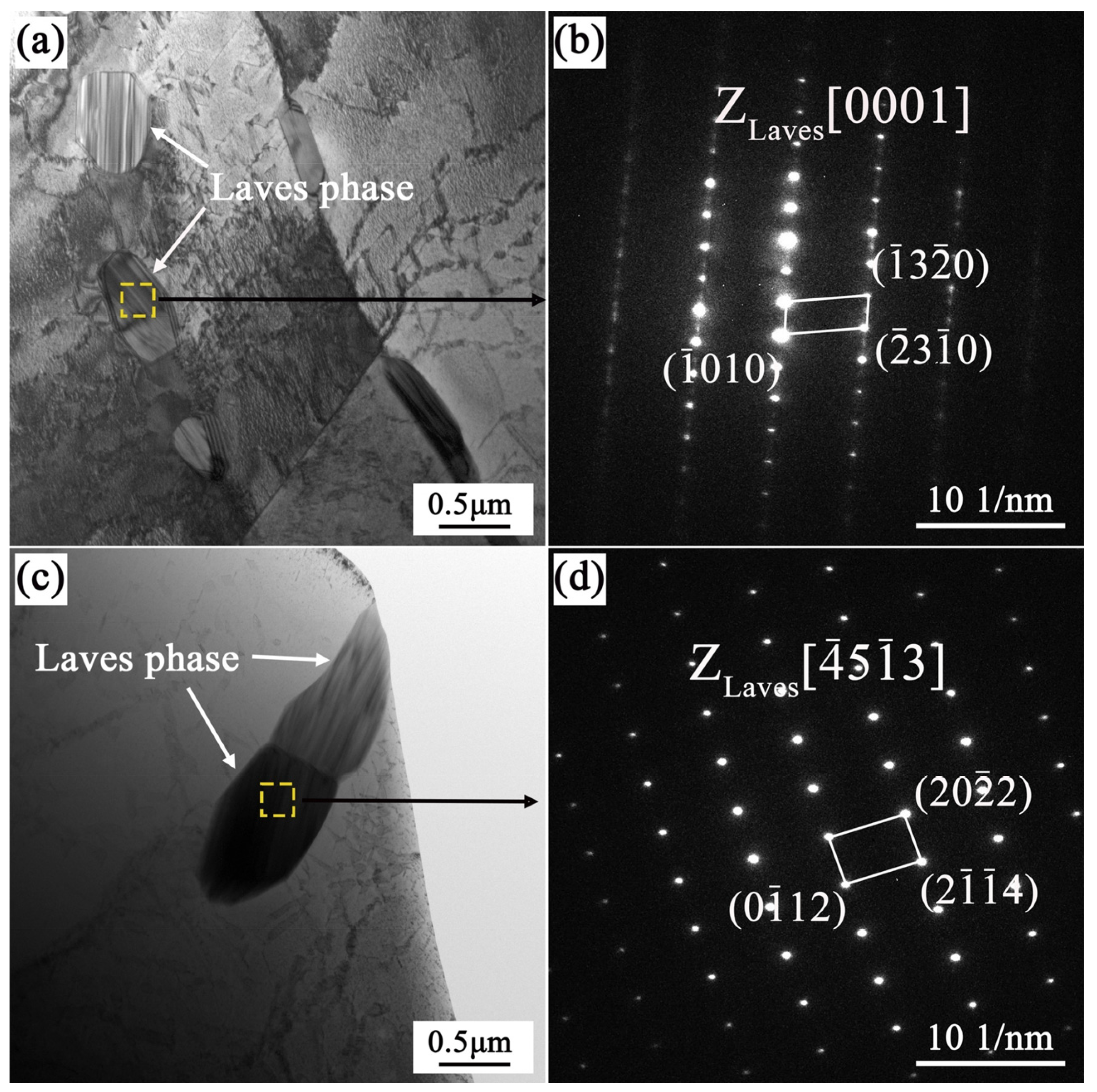
  • The Laves phase, which is used to control the grain size, continues to dissolve as the solution temperature increases. The precipitation of Laves phase decreased, and the lack of an effective grain growth inhibition mechanism resulted in a large number of grain growth.
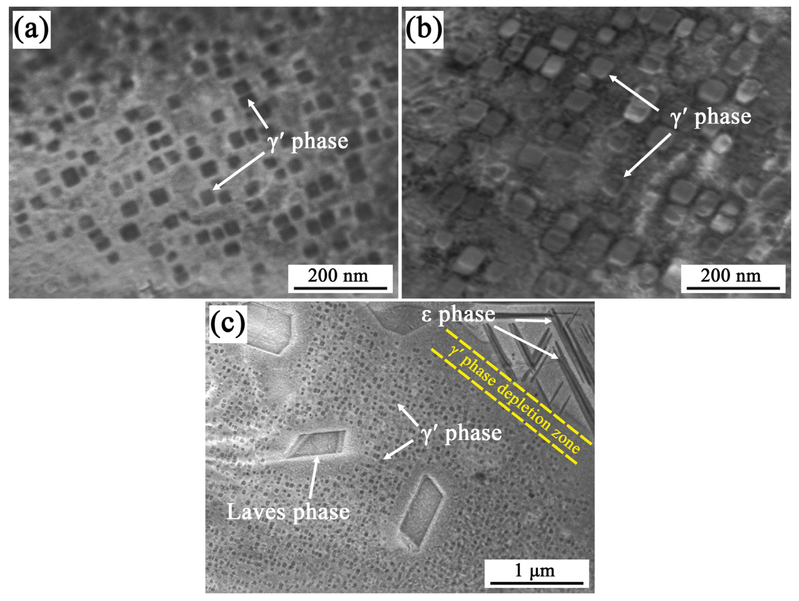
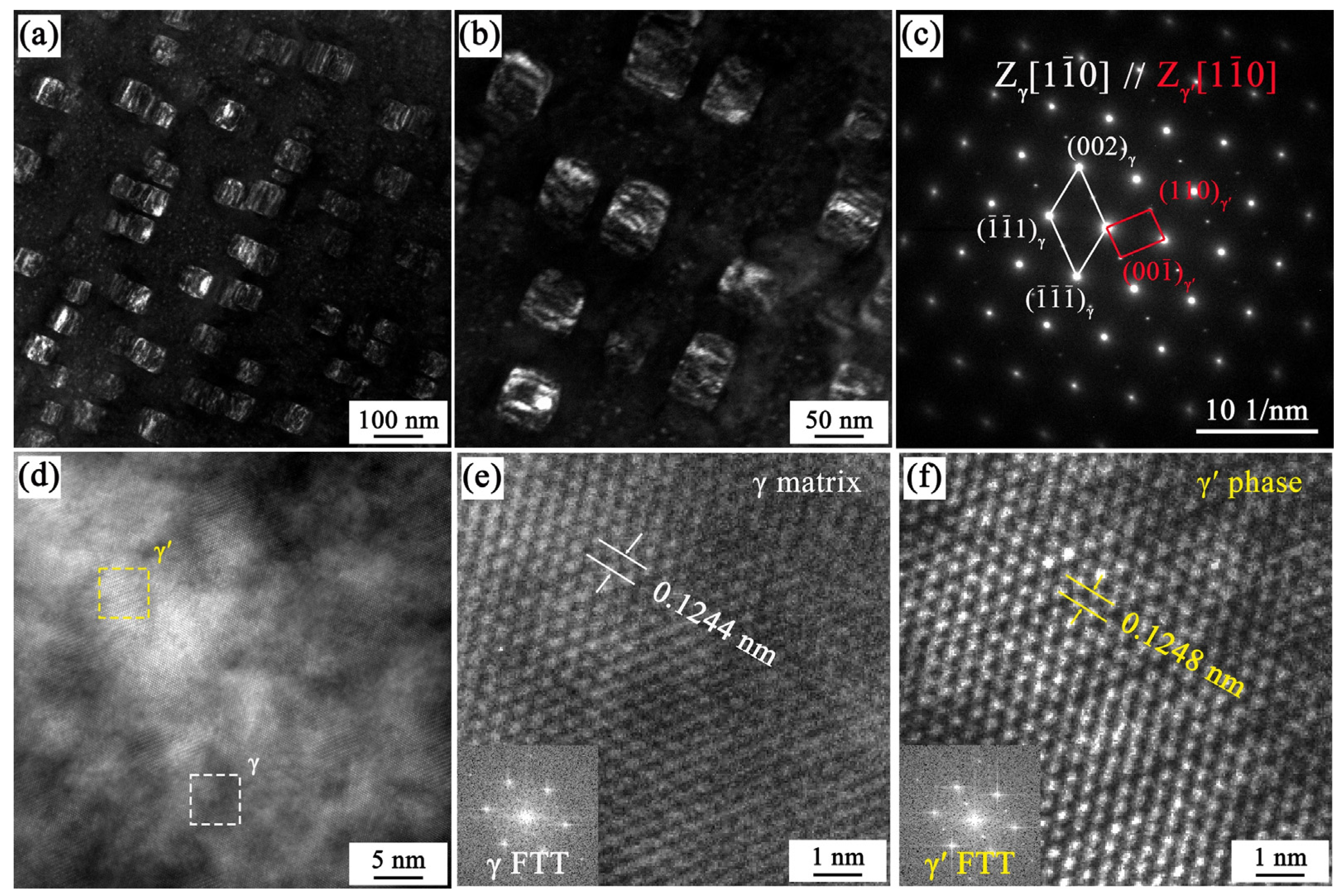
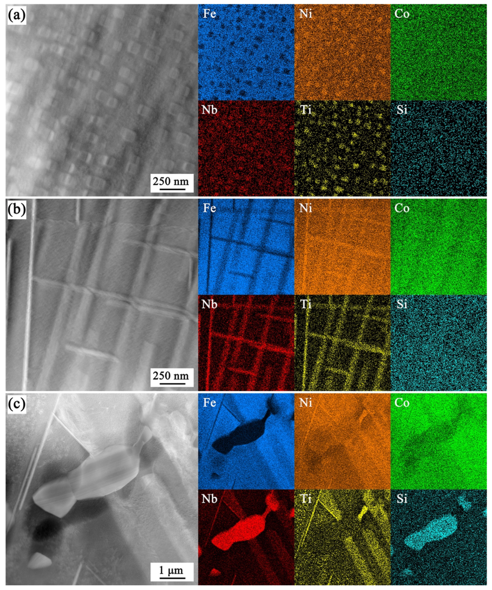
  • After solid solution and double aging treatment, a large number of disc-shaped ε phases were precipitated in the GH2097 alloy crystal, which showed a Widmanstatten-type structure in the cross arrangement and was converted from the γ′ phase. The γ′ (Ni3TiNb) phase co-grid with the matrix grows, and the size of the γ′ phase increases with the increase in Si content.
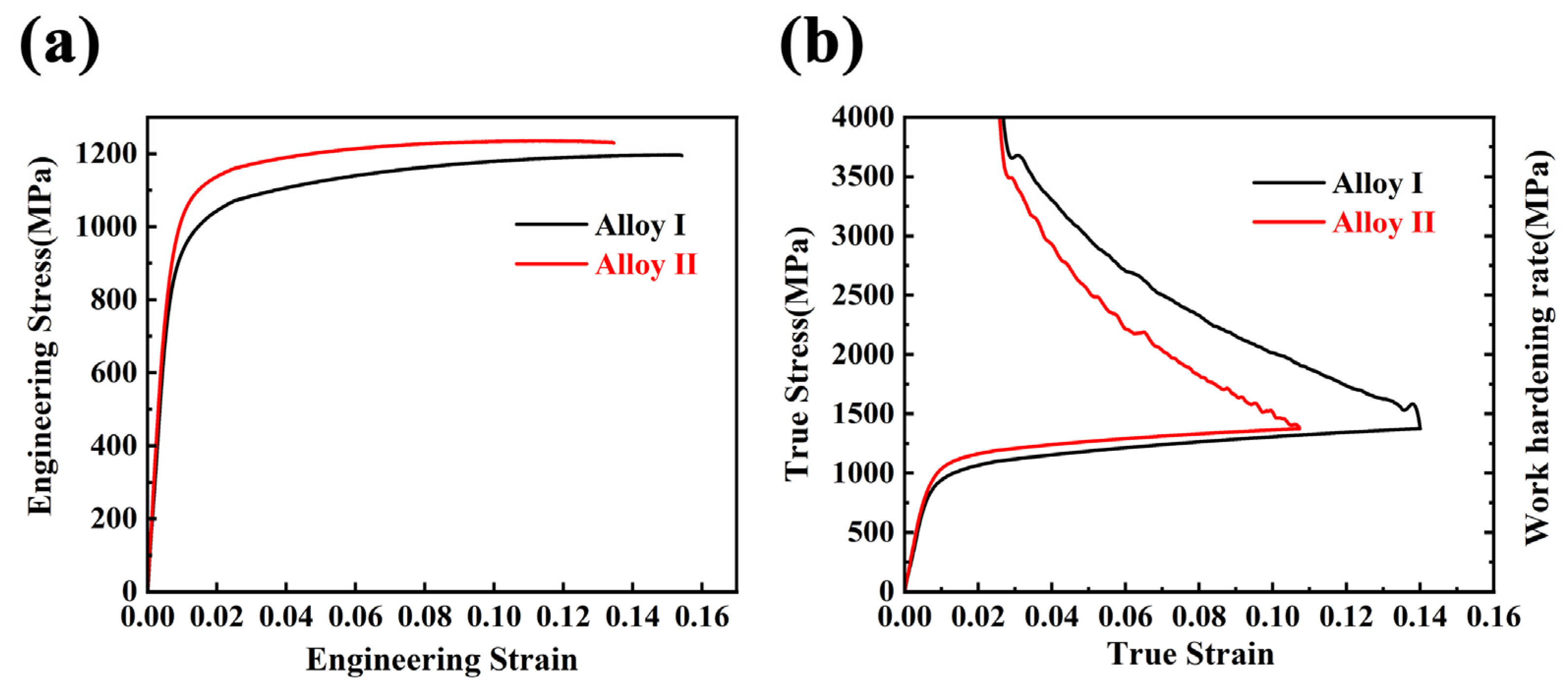
  • The main strengthening mechanism of the high-temperature treated samples was the precipitation strengthening of γ′, which contributed 52% and 53% to the yield strength of Alloy I and Alloy II.
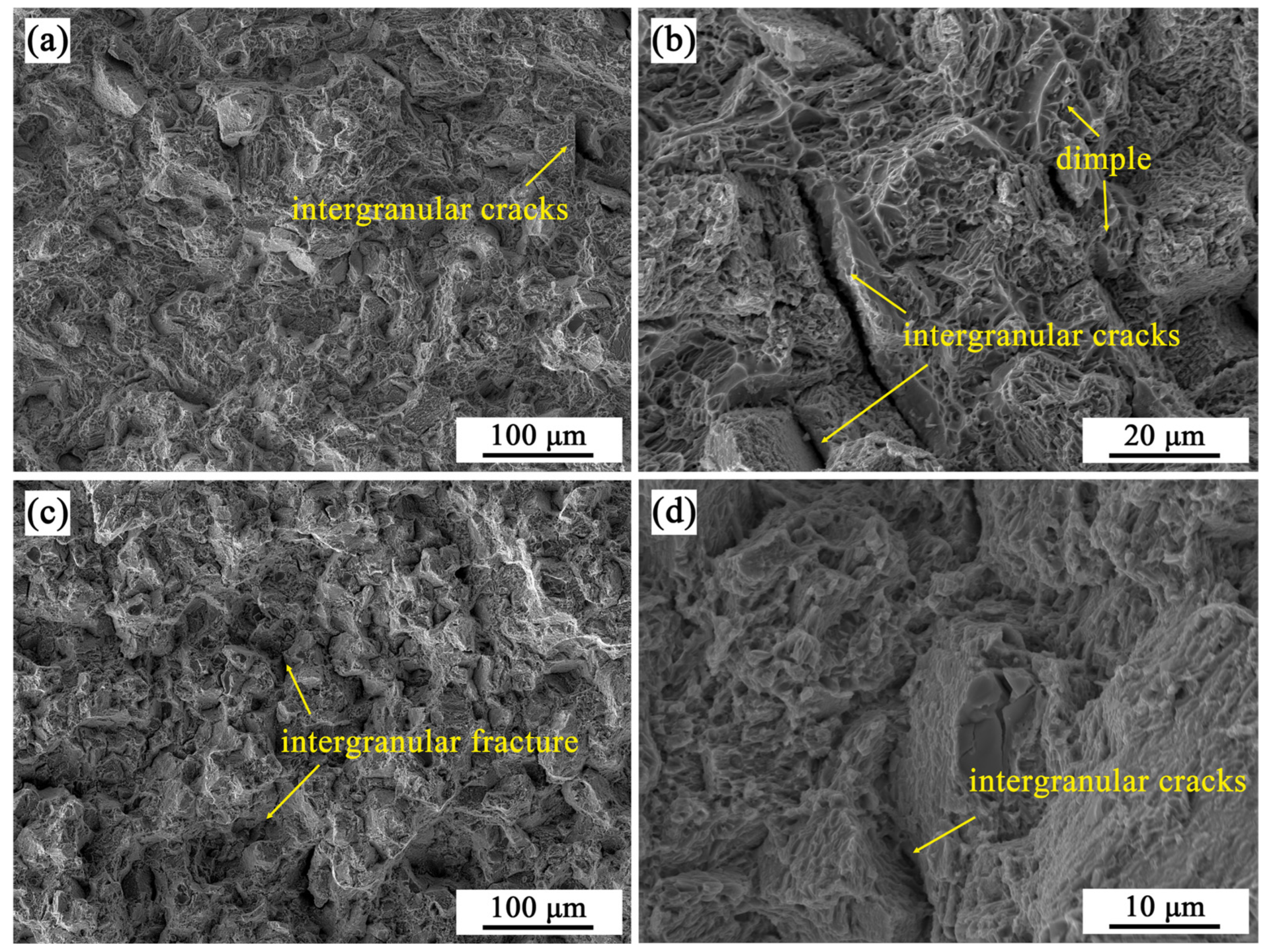
  • Discontinuous precipitation of Laves or ε phases at grain or phase boundaries can induce stress concentration, promote crack initiation, and reduce toughness. Furthermore, the γ′ phase obstructs the dislocation movement through coherent precipitation and improves the yield strength of the alloy.
  • The increase in Si content in the alloy significantly affects the formation of the precipitated phase during processing, and there are significant and complex differences in microstructure and physical metallurgy. The role of the Si element should be paid attention to in the microstructure control of the GH2907 superalloy.

Author Contributions

Conceptualization, J.W. and R.L.; methodology, M.L.; investigation, M.L. and J.W.; writing—original draft preparation, M.L. and R.L.; writing—review and editing, Z.D. and R.L.; visualization, M.L. and Z.D. All authors have read and agreed to the published version of the manuscript.

Funding

This research is financially supported by National Key Research & Development Plan (grant number: 2022YFE0110600), Natural Science Foundation of Jiangsu Province (grant number: BK20232011), National Natural Science Foundation of China (grand number: 92263201 and 51927801), and Priority Academic Program Development of Jiangsu Higher Education Institutions.

Data Availability Statement

Data are only available upon request due to private restrictions.

Conflicts of Interest

Author Jianping Wan and Zuojun Ding were employed by the company Paike New Materials Co., Ltd. The remaining authors declare that the research was conducted in the absence of any commercial or financial relationships that could be construed as a potential conflict of interest.

References

  1. Moody, N.R.; Stoltz, R.E.; Perra, M.W. The effect of hydrogen on fracture toughness of the Fe-Ni-Co superalloy IN903. Met. Trans. 1987, 18, 1469–1482. [Google Scholar] [CrossRef]
  2. Guo, X.; Kusabiraki, K.; Saji, S. Intragranular precipitates in Incoloy Alloy 909. Scr. Mater. 2001, 44, 55–60. [Google Scholar] [CrossRef]
  3. Yan, F.; Wang, C.; Wang, Y.; Hu, X.; Wang, T.; Li, J.; Li, G. A study of the mechanism of laser welding defects in low thermal expansion superalloy GH909. Mater. Charact. 2013, 78, 21–30. [Google Scholar] [CrossRef]
  4. Hayes, R.W.; Smith, D.F.; Wanner, E.A.; Earthman, J.C. Effect of environment on the rupture behavior of alloys 909 and 718. Mater. Sci. Eng. A 1994, 177, 43–53. [Google Scholar] [CrossRef]
  5. Lagow, B.W. Materials selection in gas turbine engine design and the role of low thermal expansion materials. J. Manag. 2016, 68, 2770–2775. [Google Scholar] [CrossRef]
  6. Rae, C.M.F.; Reed, R.C. The precipitation of topologically close-packed phases in rhenium-containing superalloys. Acta Mater. 2001, 49, 4113–4125. [Google Scholar] [CrossRef]
  7. Sato, K.; Ohno, T. Development of low thermal expansion superalloy. J. Mater. Eng. Perform. 1993, 2, 511–516. [Google Scholar] [CrossRef]
  8. Joseph, J.; Annasamy, M.; Cizek, P.; Vahid, A.; Hodgson, P.D.; Barnett, M.R.; Fabijanic, D.M. Design of precipitation (γ′) strengthened Fe-rich medium entropy alloys. Scr. Mater. 2023, 235, 115630. [Google Scholar] [CrossRef]
  9. Yang, W.; Zong, H.; Yang, C.; Qu, P.; Su, H.; Dong, Y.; Zhang, J.; Liu, L. The effect of Fe addition on γ′ precipitates during thermal exposure in Ni-Co-based single crystal superalloys. J. Mater. Res. Technol. 2022, 20, 894–904. [Google Scholar] [CrossRef]
  10. Chen, Z.Q.; Brooks, J.W.; Loretto, M.H. Precipitation in Incoloy alloy 909. Mater. Sci. Technol. 1993, 9, 647–653. [Google Scholar] [CrossRef]
  11. Chen, Z. Identification of orthorhombic phase in incoloy alloy 909. Scr. Metall. Mater. 1992, 26, 1077–1082. [Google Scholar] [CrossRef]
  12. Guo, X.; Kusabiraki, K. Aging an Fe-Ni-Co-Nb-Ti-Si Superalloy under tensile stress. Int. J. Mater. Res. 2000, 91, 601–606. [Google Scholar] [CrossRef]
  13. Zhang, W.; Tan, Y.; Xin, X.; Sun, W.-r. Mechanism of notch sensitivity elimination via precipitating Laves phases at grain boundaries in a low expansion superalloy. J. Mater. Res. Technol. 2022, 18, 3094–3103. [Google Scholar] [CrossRef]
  14. Ruan, T.; Shen, J.; Li, B.; Zhao, Z.; Zhang, D. High-temperature strengthening mechanism and thermal stability of Laves phase in ferritic matrix. Mater. Sci. Eng. A 2022, 859, 144183. [Google Scholar] [CrossRef]
  15. Ma, P.; Jia, Y.; Prashanth, K.G.; Yu, Z.; Li, C.; Zhao, J.; Yang, S.; Huang, L. Effect of Si content on the microstructure and properties of Al–Si alloys fabricated using hot extrusion. J. Mater. Res. 2017, 32, 2210–2217. [Google Scholar] [CrossRef]
  16. Wanner, E.A.; DeAntonio, D.A.; Smith, D.F.; Smith, J.S. The current status of controlled thermal expansion superalloys. J. Met. 1991, 43, 38–43. [Google Scholar] [CrossRef]
  17. Kusabiraki, K.; Amada, E.; Ōoka, T.; Saji, S. Epsilon and Eta phases precipitated in an Fe-38Ni-13Co-4.7Nb-1.5Ti-0.4Si superalloy. Isij Int. 1997, 37, 80–86. [Google Scholar] [CrossRef]
  18. Dobrzański, L.A.; Labisz, K.; Jonda, E.; Klimpel, A. Comparison of the surface alloying of the 32CrMoV12-28 tool steel using TiC and WC powder. J. Mater. Process. Technol. 2007, 191, 321–325. [Google Scholar] [CrossRef]
  19. Marvel, C.J.; Behler, K.D.; LaSalvia, J.C.; Haber, R.A.; Harmer, M.P. Grain boundary segregation in Si-doped B-based ceramics and its effect on grain boundary cohesion. Acta Mater. 2022, 227, 117684. [Google Scholar] [CrossRef]
  20. Singh, V.K.; Sahoo, D.; Amirthalingam, M.; Karagadde, S.; Mishra, S.K. Dissolution of the Laves phase and δ-precipitate formation mechanism in additively manufactured Inconel 718 during post printing heat treatments. Addit. Manuf. 2024, 81, 104021. [Google Scholar] [CrossRef]
  21. Zhang, Z.; Liu, J.; Zhu, C.; Wang, X.; Zhou, Y.; Wang, J.; Li, J. Investigation of the formation mechanism between β-NiAl and C14-Laves phases in laser additive manufacturing of nickel-based superalloy. Intermetallics 2024, 168, 108272. [Google Scholar] [CrossRef]
  22. Murakumo, T.; Kobayashi, T.; Koizumi, Y.; Harada, H. Creep behaviour of Ni-base single-crystal superalloys with various γ′ volume fraction. Acta Mater. 2004, 52, 3737–3744. [Google Scholar] [CrossRef]
  23. Liu, W.B.; Liu, Z.; Luo, W.; Zuo, D.; Liu, H.Q.; Zhang, R.Q.; Wang, Q. Effect of Zr addition on coarse Laves phase stimulated nucleation of recrystallization in FeCrAl alloy. Mater. Sci. Eng. A 2022, 840, 142964. [Google Scholar] [CrossRef]
  24. Lv, P.; Liu, L.; Yang, Y.; Zhao, Y.; Zhang, J. Role of microstructural stability and superdislocation shearing on creep behavior of two low-cost Ni-based single crystal superalloys at 1100 °C/130 MPa. Mater. Sci. Eng. A 2023, 888, 145796. [Google Scholar] [CrossRef]
  25. Kishore, K.; Chandan, A.K.; Hung, P.T.; Kumar, S.; Ranjan, M.; Kawasaki, M.; Gubicza, J. Effect of Si on the evolution of plasticity mechanisms, grain refinement and hardness during high-pressure torsion of a non-equiatomic CoCrMnNi multi-principal element alloy. Int. J. Plast. 2023, 169, 103720. [Google Scholar] [CrossRef]
  26. Wu, Y.; Li, C.; Xia, X.; Liang, H.; Qi, Q.; Liu, Y. Precipitate coarsening and its effects on the hot deformation behavior of the recently developed γ’-strengthened superalloys. J. Mater. Sci. Technol. 2021, 67, 95–104. [Google Scholar] [CrossRef]
  27. Reed, R. The Superalloys Fundamentals and Applications; Cambridge University Press: Cambridge, UK, 2006; pp. 74–86. [Google Scholar]
  28. Peng, Z.; Tian, G.; Jiang, J.; Li, M.; Chen, Y.; Zou, J.; Dunne, F.P.E. Mechanistic behaviour and modelling of creep in powder metallurgy FGH96 nickel superalloy. Mater. Sci. Eng. A 2016, 676, 441–449. [Google Scholar] [CrossRef]
  29. Goodfellow, A.J. Strengthening mechanisms in polycrystalline nickel-based superalloys. Mater. Sci. Technol. 2018, 34, 1793–1808. [Google Scholar] [CrossRef]
  30. Kozar, R.W.; Suzuki, A.; Milligan, W.W.; Schirra, J.J.; Savage, M.F.; Pollock, T.M. Strengthening mechanisms in polycrystalline multimodal nickel-base superalloys. Metall. Mater. Trans. A 2009, 40, 1588–1603. [Google Scholar] [CrossRef]
  31. Roth, H.A.; Davis, C.L.; Thomson, R.C. Modeling solid solution strengthening in nickel alloys. Metall. Mater. Trans. A 1997, 28, 1329–1335. [Google Scholar] [CrossRef]
  32. Galindo-Nava, E.I.; Connor, L.D.; Rae, C.M.F. On the prediction of the yield stress of unimodal and multimodal γ′ Nickel-base superalloys. Acta Mater. 2015, 98, 377–390. [Google Scholar] [CrossRef]
  33. Xu, J.; Gruber, H.; Boyd, R.; Jiang, S.; Peng, R.L.; Moverare, J.J. On the strengthening and embrittlement mechanisms of an additively manufactured Nickel-base superalloy. Materialia 2020, 10, 100657. [Google Scholar] [CrossRef]
  34. Yang, B.; Shang, Z.; Ding, J.; Lopez, J.; Jarosinski, W.; Sun, T.; Richter, N.; Zhang, Y.; Wang, H.; Zhang, X. Investigation of strengthening mechanisms in an additively manufactured Haynes 230 alloy. Acta Mater. 2022, 222, 117404. [Google Scholar] [CrossRef]
  35. Kim, Y.-K.; Choe, J.; Lee, K.-A. Selective laser melted equiatomic CoCrFeMnNi high-entropy alloy: Microstructure, anisotropic mechanical response, and multiple strengthening mechanism. J. Alloys Compd. 2019, 805, 680–691. [Google Scholar] [CrossRef]
  36. Mughrabi, H. A two-parameter description of heterogeneous dislocation distributions in deformed metal crystals. Mater. Sci. Eng. 1987, 85, 15–31. [Google Scholar] [CrossRef]
  37. Jiang, S.; Shen, J.; Nagasaka, T.; Muroga, T.; Sagara, A.; Ohnuki, S.; Hokamoto, K.; Tanaka, S.; Inao, D.; Morizono, Y.; et al. Interfacial characterization of dissimilar-metals bonding between vanadium alloy and Hastelloy X alloy by explosive welding. J. Nucl. Mater. 2020, 539, 152322. [Google Scholar] [CrossRef]
  38. Rajendran, R.; Petley, V.; Rehmer, B. Dynamic elastic properties of aero-engine metallic isotropic materials. Proc. Inst. Mech. Eng. Part L J. Mater. Des. Appl. 2012, 227, 243–249. [Google Scholar] [CrossRef]
  39. Xu, J.; Lin, X.; Guo, P.; Yang, H.; Xue, L.; Huang, W. The microstructure evolution and strengthening mechanism of a γ′-strengthening superalloy prepared by induction-assisted laser solid forming. J. Alloys Compd. 2019, 780, 461–475. [Google Scholar] [CrossRef]
  40. Liu, X.; Hu, R.; Yang, C.; Luo, X.; Bai, J.; Ma, R. Microstructure evolution and strengthening mechanism of γ′-strengthening superalloy prepared by laser powder bed fusion. Mater. Sci. Eng. A 2023, 871, 144915. [Google Scholar] [CrossRef]
  41. Baik, S.-I.; Wang, S.-Y.; Liaw, P.K.; Dunand, D.C. Increasing the creep resistance of Fe-Ni-Al-Cr superalloys via Ti additions by optimizing the B2/L21 ratio in composite nano-precipitates. Acta Mater. 2018, 157, 142–154. [Google Scholar] [CrossRef]
  42. Lu, W.; Yan, K.; Luo, X.; Wang, Y.; Hou, L.; Li, P.; Huang, B.; Yang, Y. Superb strength and ductility balance of a Co-free medium-entropy alloy with dual heterogeneous structures. J. Mater. Sci. Technol. 2022, 98, 197–204. [Google Scholar] [CrossRef]
  43. Wang, J.-S. Dislocation nucleation and the intrinsic fracture behavior of L12 intermetallic alloys. Acta Mater. 1998, 46, 2663–2674. [Google Scholar] [CrossRef]
  44. Liu, X.; Liu, Y.; Zhou, Z.; Wang, K.; Zhan, Q.; Xiao, X. Grain refinement and crack inhibition of selective laser melted AA2024 aluminum alloy via inoculation with TiC–TiH2. Mater. Sci. Eng. A 2021, 813, 141171. [Google Scholar] [CrossRef]
  45. Lee, J.-U.; Kim, Y.-K.; Seo, S.-M.; Lee, K.-A. Effects of hot isostatic pressing treatment on the microstructure and tensile properties of Ni-based superalloy CM247LC manufactured by selective laser melting. Mater. Sci. Eng. A 2022, 841, 143083. [Google Scholar] [CrossRef]
Figure 1. EBSD inverse pole figure maps of the as-forged Alloy I (a) and Alloy II (c), and the corresponding grain size statistical distributions of Alloy I (b) and Alloy II (d).
Metals 15 00484 g001
Figure 2. TEM images of the Laves phase in the as-forged samples: (a) Alloy I; (b) SAED pattern of Laves phase in Alloy I; (c) Alloy II; (d) SAED pattern of Laves phase in Alloy II.
Metals 15 00484 g002
Figure 3. TEM images of the γ′ phase in the as-forged samples: (a) TEM image of the γ′ phase in Alloy I; (b) SAED pattern of γ′ phase in Alloy I; (c) TEM image of the γ′ phase in Alloy II; (d) SAED pattern of γ′ phase in Alloy II.
Metals 15 00484 g003
Figure 4. SEM images of samples subjected to various solution treatments: (a) Alloy I subjected to SII treatment; (b) Alloy I subjected to SIII treatment; (c) Alloy I subjected to SIV treatment; (d) Alloy II sample subjected to SII treatment; (e) Alloy II sample subjected to SIII treatment; (f) Alloy II sample subjected to SIV treatment.
Metals 15 00484 g004
Figure 5. BSE images of samples subjected to solution at 980 °C and two-stage aging treatment: (a,b) Alloy I; (c,d) Alloy II.
Metals 15 00484 g005
Figure 6. TEM images of the ε phase in the samples subjected to solution at 980 °C and two-stage aging treatment: (a) Alloy I; (b) SAED pattern of the ε phase in Alloy I; (c) Alloy II; (d) SAED pattern of the ε phase in Alloy II.
Metals 15 00484 g006
Figure 7. STEM images of γ′ phase in the samples subjected to solution at 980 °C and two-stage aging treatment: (a) Alloy I; (b,c) Alloy II.
Metals 15 00484 g007
Figure 8. TEM images of γ′ precipitates: (a,b) DF TEM image of the marked diffraction in (c) of γ′ precipitates. (c) SAED pattern; (d) a high-resolution TEM image of γ/γ′ phases; (e,f) magnified views of γ matrix (boxed by white lines) and γ′ precipitates (boxed by yellow lines) with fast Fourier transform (FFT) images embedded.
Metals 15 00484 g008
Figure 9. BF-STEM image and corresponding STEM-EDX element maps showing the relative chemical composition of precipitates of Alloy II: (a) γ′ phase, (b) ε phase, (c) Laves phase.
Metals 15 00484 g009
Figure 10. (a) The engineering stress–strain curves and (b) the work hardening rate versus true strain curves.
Metals 15 00484 g010
Figure 11. The fracture morphologies of samples subjected to solution and two-stage aging treatment: (a,b) Alloy I; (c,d) Alloy II.
Metals 15 00484 g011
Figure 12. The contribution of each strengthening mechanism to Alloy I and Alloy II samples was compared.
Metals 15 00484 g012
Table 1. Contrast of chemical composition of GH2907 alloys (wt.%).
FeSiCoNbTiNi
Alloy I40.980.2213.885.051.78Bal
Alloy II40.10.3413.875.071.76Bal
Table 2. Heat treatment processes of GH2907 in the present work.
ProcessHeat Treatment
SIAs forged
SII980 °C, 1 h, AC
SIII990 °C, 1 h, AC
SIV1000 °C, 1 h, AC
SV980 °C, 1 h, AC + 770 °C, 12 h, FC (0.9 °C·min−1) to 621 °C, 8 h, AC
Table 3. Mechanical properties of Alloy I and Alloy II.
Alloy IAlloy II
Yield strength (MPa)890.3 ± 1987.4 ± 1
Ultimate tensile strength (MPa)1197.2 ± 41224.0 ± 11
Uniform elongation (%)15.33 ± 0.0411.12 ± 0.07
Fracture elongation (%)15.42 ± 0.613.05 ± 0.4
Disclaimer/Publisher’s Note: The statements, opinions and data contained in all publications are solely those of the individual author(s) and contributor(s) and not of MDPI and/or the editor(s). MDPI and/or the editor(s) disclaim responsibility for any injury to people or property resulting from any ideas, methods, instructions or products referred to in the content.

